EP2631325A2 - Coating and coating method for gas turbine component - Google Patents
Coating and coating method for gas turbine component Download PDFInfo
- Publication number
- EP2631325A2 EP2631325A2 EP13155956.9A EP13155956A EP2631325A2 EP 2631325 A2 EP2631325 A2 EP 2631325A2 EP 13155956 A EP13155956 A EP 13155956A EP 2631325 A2 EP2631325 A2 EP 2631325A2
- Authority
- EP
- European Patent Office
- Prior art keywords
- region
- coating
- chromium
- aluminum
- bearing
- Prior art date
- Legal status (The legal status is an assumption and is not a legal conclusion. Google has not performed a legal analysis and makes no representation as to the accuracy of the status listed.)
- Withdrawn
Links
Images


Classifications
-
- C—CHEMISTRY; METALLURGY
- C25—ELECTROLYTIC OR ELECTROPHORETIC PROCESSES; APPARATUS THEREFOR
- C25D—PROCESSES FOR THE ELECTROLYTIC OR ELECTROPHORETIC PRODUCTION OF COATINGS; ELECTROFORMING; APPARATUS THEREFOR
- C25D5/00—Electroplating characterised by the process; Pretreatment or after-treatment of workpieces
- C25D5/10—Electroplating with more than one layer of the same or of different metals
- C25D5/12—Electroplating with more than one layer of the same or of different metals at least one layer being of nickel or chromium
-
- C—CHEMISTRY; METALLURGY
- C23—COATING METALLIC MATERIAL; COATING MATERIAL WITH METALLIC MATERIAL; CHEMICAL SURFACE TREATMENT; DIFFUSION TREATMENT OF METALLIC MATERIAL; COATING BY VACUUM EVAPORATION, BY SPUTTERING, BY ION IMPLANTATION OR BY CHEMICAL VAPOUR DEPOSITION, IN GENERAL; INHIBITING CORROSION OF METALLIC MATERIAL OR INCRUSTATION IN GENERAL
- C23C—COATING METALLIC MATERIAL; COATING MATERIAL WITH METALLIC MATERIAL; SURFACE TREATMENT OF METALLIC MATERIAL BY DIFFUSION INTO THE SURFACE, BY CHEMICAL CONVERSION OR SUBSTITUTION; COATING BY VACUUM EVAPORATION, BY SPUTTERING, BY ION IMPLANTATION OR BY CHEMICAL VAPOUR DEPOSITION, IN GENERAL
- C23C10/00—Solid state diffusion of only metal elements or silicon into metallic material surfaces
- C23C10/02—Pretreatment of the material to be coated
-
- C—CHEMISTRY; METALLURGY
- C23—COATING METALLIC MATERIAL; COATING MATERIAL WITH METALLIC MATERIAL; CHEMICAL SURFACE TREATMENT; DIFFUSION TREATMENT OF METALLIC MATERIAL; COATING BY VACUUM EVAPORATION, BY SPUTTERING, BY ION IMPLANTATION OR BY CHEMICAL VAPOUR DEPOSITION, IN GENERAL; INHIBITING CORROSION OF METALLIC MATERIAL OR INCRUSTATION IN GENERAL
- C23C—COATING METALLIC MATERIAL; COATING MATERIAL WITH METALLIC MATERIAL; SURFACE TREATMENT OF METALLIC MATERIAL BY DIFFUSION INTO THE SURFACE, BY CHEMICAL CONVERSION OR SUBSTITUTION; COATING BY VACUUM EVAPORATION, BY SPUTTERING, BY ION IMPLANTATION OR BY CHEMICAL VAPOUR DEPOSITION, IN GENERAL
- C23C10/00—Solid state diffusion of only metal elements or silicon into metallic material surfaces
- C23C10/28—Solid state diffusion of only metal elements or silicon into metallic material surfaces using solids, e.g. powders, pastes
- C23C10/34—Embedding in a powder mixture, i.e. pack cementation
- C23C10/58—Embedding in a powder mixture, i.e. pack cementation more than one element being diffused in more than one step
-
- C—CHEMISTRY; METALLURGY
- C25—ELECTROLYTIC OR ELECTROPHORETIC PROCESSES; APPARATUS THEREFOR
- C25D—PROCESSES FOR THE ELECTROLYTIC OR ELECTROPHORETIC PRODUCTION OF COATINGS; ELECTROFORMING; APPARATUS THEREFOR
- C25D13/00—Electrophoretic coating characterised by the process
- C25D13/02—Electrophoretic coating characterised by the process with inorganic material
-
- C—CHEMISTRY; METALLURGY
- C25—ELECTROLYTIC OR ELECTROPHORETIC PROCESSES; APPARATUS THEREFOR
- C25D—PROCESSES FOR THE ELECTROLYTIC OR ELECTROPHORETIC PRODUCTION OF COATINGS; ELECTROFORMING; APPARATUS THEREFOR
- C25D13/00—Electrophoretic coating characterised by the process
- C25D13/12—Electrophoretic coating characterised by the process characterised by the article coated
- C25D13/16—Wires; Strips; Foils
-
- C—CHEMISTRY; METALLURGY
- C25—ELECTROLYTIC OR ELECTROPHORETIC PROCESSES; APPARATUS THEREFOR
- C25D—PROCESSES FOR THE ELECTROLYTIC OR ELECTROPHORETIC PRODUCTION OF COATINGS; ELECTROFORMING; APPARATUS THEREFOR
- C25D3/00—Electroplating: Baths therefor
- C25D3/02—Electroplating: Baths therefor from solutions
- C25D3/04—Electroplating: Baths therefor from solutions of chromium
-
- C—CHEMISTRY; METALLURGY
- C25—ELECTROLYTIC OR ELECTROPHORETIC PROCESSES; APPARATUS THEREFOR
- C25D—PROCESSES FOR THE ELECTROLYTIC OR ELECTROPHORETIC PRODUCTION OF COATINGS; ELECTROFORMING; APPARATUS THEREFOR
- C25D5/00—Electroplating characterised by the process; Pretreatment or after-treatment of workpieces
- C25D5/02—Electroplating of selected surface areas
- C25D5/022—Electroplating of selected surface areas using masking means
-
- C—CHEMISTRY; METALLURGY
- C25—ELECTROLYTIC OR ELECTROPHORETIC PROCESSES; APPARATUS THEREFOR
- C25D—PROCESSES FOR THE ELECTROLYTIC OR ELECTROPHORETIC PRODUCTION OF COATINGS; ELECTROFORMING; APPARATUS THEREFOR
- C25D5/00—Electroplating characterised by the process; Pretreatment or after-treatment of workpieces
- C25D5/34—Pretreatment of metallic surfaces to be electroplated
- C25D5/42—Pretreatment of metallic surfaces to be electroplated of light metals
- C25D5/44—Aluminium
-
- C—CHEMISTRY; METALLURGY
- C25—ELECTROLYTIC OR ELECTROPHORETIC PROCESSES; APPARATUS THEREFOR
- C25D—PROCESSES FOR THE ELECTROLYTIC OR ELECTROPHORETIC PRODUCTION OF COATINGS; ELECTROFORMING; APPARATUS THEREFOR
- C25D5/00—Electroplating characterised by the process; Pretreatment or after-treatment of workpieces
- C25D5/48—After-treatment of electroplated surfaces
- C25D5/50—After-treatment of electroplated surfaces by heat-treatment
-
- F—MECHANICAL ENGINEERING; LIGHTING; HEATING; WEAPONS; BLASTING
- F01—MACHINES OR ENGINES IN GENERAL; ENGINE PLANTS IN GENERAL; STEAM ENGINES
- F01D—NON-POSITIVE DISPLACEMENT MACHINES OR ENGINES, e.g. STEAM TURBINES
- F01D5/00—Blades; Blade-carrying members; Heating, heat-insulating, cooling or antivibration means on the blades or the members
- F01D5/12—Blades
- F01D5/28—Selecting particular materials; Particular measures relating thereto; Measures against erosion or corrosion
- F01D5/288—Protective coatings for blades
-
- F—MECHANICAL ENGINEERING; LIGHTING; HEATING; WEAPONS; BLASTING
- F01—MACHINES OR ENGINES IN GENERAL; ENGINE PLANTS IN GENERAL; STEAM ENGINES
- F01D—NON-POSITIVE DISPLACEMENT MACHINES OR ENGINES, e.g. STEAM TURBINES
- F01D5/00—Blades; Blade-carrying members; Heating, heat-insulating, cooling or antivibration means on the blades or the members
- F01D5/30—Fixing blades to rotors; Blade roots ; Blade spacers
- F01D5/3007—Fixing blades to rotors; Blade roots ; Blade spacers of axial insertion type
-
- F—MECHANICAL ENGINEERING; LIGHTING; HEATING; WEAPONS; BLASTING
- F05—INDEXING SCHEMES RELATING TO ENGINES OR PUMPS IN VARIOUS SUBCLASSES OF CLASSES F01-F04
- F05D—INDEXING SCHEME FOR ASPECTS RELATING TO NON-POSITIVE-DISPLACEMENT MACHINES OR ENGINES, GAS-TURBINES OR JET-PROPULSION PLANTS
- F05D2230/00—Manufacture
- F05D2230/30—Manufacture with deposition of material
- F05D2230/31—Layer deposition
-
- F—MECHANICAL ENGINEERING; LIGHTING; HEATING; WEAPONS; BLASTING
- F05—INDEXING SCHEMES RELATING TO ENGINES OR PUMPS IN VARIOUS SUBCLASSES OF CLASSES F01-F04
- F05D—INDEXING SCHEME FOR ASPECTS RELATING TO NON-POSITIVE-DISPLACEMENT MACHINES OR ENGINES, GAS-TURBINES OR JET-PROPULSION PLANTS
- F05D2300/00—Materials; Properties thereof
- F05D2300/10—Metals, alloys or intermetallic compounds
- F05D2300/12—Light metals
- F05D2300/121—Aluminium
-
- F—MECHANICAL ENGINEERING; LIGHTING; HEATING; WEAPONS; BLASTING
- F05—INDEXING SCHEMES RELATING TO ENGINES OR PUMPS IN VARIOUS SUBCLASSES OF CLASSES F01-F04
- F05D—INDEXING SCHEME FOR ASPECTS RELATING TO NON-POSITIVE-DISPLACEMENT MACHINES OR ENGINES, GAS-TURBINES OR JET-PROPULSION PLANTS
- F05D2300/00—Materials; Properties thereof
- F05D2300/10—Metals, alloys or intermetallic compounds
- F05D2300/13—Refractory metals, i.e. Ti, V, Cr, Zr, Nb, Mo, Hf, Ta, W
- F05D2300/132—Chromium
Definitions
- the present invention relates to a protective coating for a gas turbine blade or other component wherein the coating includes an aluminum-bearing coating applied at a relatively high temperature region of the component and a chromium-bearing coating applied at another relatively lower temperature region of the component depending on coating functionality needed.
- Hot corrosion is a form of accelerated oxidation when a liquid salt is present on the surface of a Ni and Co based superalloy component.
- the salt is usually sodium sulfate with other naturally occurring constituents, such as K, Ca, and/or Mg, present.
- Current methods to increase surface Cr content are pack and vapor phase chromizing, which comprise one-step deposition and reaction with the Ni substrate alloy, forming a Cr-enriched alloy zone. The chromizing process is facilitated by halide (Cl or F) activators that form Cr-halide gases at relatively high temperatures, such as greater than 1038 °C (1900 degrees F).
- pack and vapor phase chromizing require high temperature application above 1038 °C (1900 degrees F) and are difficult to apply to localized part areas of interest, these processes must be applied early in the part routing to the entire the part. Masking has not been effective in these processes as a means for controlling the localized deposition of the chromium on certain areas of interest and, as a result, has not been applied in these high temperature processes.
- the present invention provides in an embodiment a method of forming a protective coating on a gas turbine component wherein the duplex coating includes an aluminum-bearing coating applied at one region of the gas turbine component where relatively higher temperatures are encountered in service and a chromium-bearing coating applied at another region of the turbine blade or other component where relatively lower temperatures and hot corrosion are encountered in service, thereby providing coating functionality for the different temperatures and oxidation/corrosion environments to be encountered by the gas turbine component.
- the method involves forming a duplex coating on a superalloy substrate by first applying an aluminum-bearing coating on the first relatively higher temperature region of the substrate, secondly applying a metallic coating comprising chromium on an adjacent relatively lower temperature region of the substrate followed by diffusing chromium into the substrate to form a chromium-enriched diffused coating thereon at the adjacent relatively lower temperature region.
- the aluminum-bearing coating is applied in a first step by high temperature vapor deposition, while the chromium-bearing coating is applied in a subsequent second step at a relatively lower temperature, such as less than 260 °C (500 degrees F).
- the method typically involves applying masking on the relatively lower temperature region before the aluminum-bearing coating is applied on the relatively higher temperature region and subsequently applying masking on the relatively higher temperature region before the metallic coating of chromium is applied on the relatively lower temperature region.
- the method is practiced by first applying a mask on a root region of the component, then applying an aluminum-bearing coating, such as a diffusion aluminide coating, on an airfoil region, de-masking the root portion, and then masking the already-coated airfoil region. Then, the method involves depositing a metallic coating comprising chromium on at least a portion of a relatively lower temperature root region that will be subject to hot corrosion, de-masking the airfoil region followed by diffusing the chromium into the alloy at the coated portion of the root region to form a chromium-enriched diffused surface coating on the portion of the root region.
- an aluminum-bearing coating such as a diffusion aluminide coating
- the aluminum-bearing coating optionally can be applied to cover the airfoil region and also an intermediate platform region and root shank region.
- An attachment portion, such as a fir tree portion, of the root region may be left uncoated to enhance fatigue life of the root region where it is connected to a turbine disk.
- a relatively low temperature deposition process embodying a liquid deposition medium, such as electroplating bath, electrophoretic bath, liquid slurry, and others, is used to form a metallic coating comprising a majority of chromium on at least a portion of the relatively lower temperature region of a precursor component.
- the chromium coating is applied as a very thin layer having a thickness of 0.00127 to 0.127 mm (0.00005 to 0.005 inch). Diffusion of the as-deposited chromium into the substrate typically is effected by elevated temperature heat treatment after the masking is removed from the previously-applied aluminum-bearing coating on the airfoil region.
- the present invention envisions a nickel or cobalt based alloy turbine component precursor having an aluminum-bearing coating applied on an airfoil region and metallic coating comprising substantially pure chromium or a chromium alloy applied on at least a portion of the root region of the component.
- the chromium coating then is diffused into the alloy to form a diffused chromium-enriched coating on the portion of the root region of the gas turbine blade.
- the diffused chromium-enriched coating has an outermost region that comprises at least about 20%, preferably about 25%, and more preferably about 30% to about 60% by weight Cr.
- a method for forming a protective coating on a gas turbine component wherein the coating includes an aluminum-bearing coating applied at one region of the turbine blade or other component where relatively higher temperatures are encountered in service and a chromium-bearing coating formed at another adjacent region of the component where relatively lower temperatures and hot corrosion are encountered in service.
- a duplex coating provides coating functionality for the different temperatures and oxidation/corrosion environments to be encountered in service.
- the present invention is especially useful for protecting different regions of a gas turbine blade component from oxidation and hot corrosion in service in a gas turbine engine, although the invention is not limited to gas turbine components since it can be practiced to protect other components against oxidation and hot corrosion.
- the present invention can be practiced to protect nickel based superalloy gas turbine components, nickel-cobalt based superalloy gas turbine components, or cobalt based superalloy gas turbine components from hot corrosion, although the invention is not limited to these alloys.
- the present invention will be described below with respect to protection of different regions of a gas turbine engine blade made of CMSX-4 nickel based superalloy against oxidation and hot corrosion in service in a gas turbine engine.
- Figure 1 shows an exemplary gas turbine blade 10 having an airfoil region 12, a root region 14 and an intermediate platform region 20 between the airfoil and root regions.
- the airfoil 12 includes a tip 12a, a leading edge 12b, and trailing edge 12c subjected to the gas path of the engine turbine section.
- a platform region 20 typically separates the gas-path surfaces from non-gas path surfaces and includes an upper platform surface facing the gas path and an lower platform surface facing away from the gas path.
- the root region 14 includes non-gas path surfaces beneath the lower side of the platform region 20 wherein the root region includes a an attachment portion 16, such as a conventional fir tree portion, by which the turbine blade is connected to the turbine disk (not shown) in usual manner and an adjacent shank portion 18 between the attachment portion 16 and the platform region 20.
- the fir tree typically comprises machined serrations which fit into the turbine disk and which can be machined before or after coating pursuant to customer specifications.
- the shank region 18 includes the region between the fir tree and lower side of the platform region 20 and may include as-cast and machined surfaces as well as features to aid sealing the gas path from the non-gas path regions.
- a first hotter region of the turbine blade 10 is subjected to relatively higher temperatures and oxidation degradation in service in the gas turbine engine and comprises the airfoil region 12 and surface 20a of a platform region 20 that faces toward the airfoil region such that the airfoil region 12 and platform surface 20a operate in or near the hot gas path of the turbine section of the gas turbine engine.
- the airfoil region 12 and platform surface 20a are the hottest regions of the turbine blade and usually operate above 1038 °C (1900 degrees F) for purposes of illustration and not limitation.
- the airfoil region 12 and the platform surface 20a preferably are provided with a so-called alumina-former coating thereon that produces an adherent protective scale of alumina in service in the gas turbine engine.
- a second relatively cooler region of the turbine blade 10 is subjected to relatively lower temperatures and hot corrosion by salts, such as sodium sulfates and other constituents such as K, Ca, and/or Mg, in service in the gas turbine engine.
- the second region comprises the under (lower) surface 20b of a platform region 20 that faces away from the airfoil region 12 and the root region 14.
- the second region thus involves a cooler region that on older turbine blades may operate uncoated.
- the operating temperature of the second region is generally increasing and spread more uniformly over the second region.
- the first region comprised of the airfoil 12 and platform surface surface 20a is also becoming hotter.
- hot corrosion attack can occur.
- rapid attack and fracture of the turbine blade in the root region can occur.
- hot corrosion resistance can be increased by increasing the chromium content of the turbine blade alloy.
- the present invention provides a multiplex coating and a method for applying the coating to protect the different hotter and cooler regions of the turbine blade exposed to more aggressive temperature/hot corrosion conditions associated recent engine designs.
- the present invention provides a nickel or cobalt based alloy turbine blade 10 having an aluminum-bearing coating AL applied on an airfoil region of the blade and a metallic coating comprising chromium applied on at least a portion of the root region of the blade and diffused into the alloy to form the diffused chromium-enriched coating CR on the portion of the root region.
- Figure 1 illustrates the aluminum-bearing coating AL and the chromium-bearing diffused coating CR on the airfoil and the root portion, respectively.
- the aluminum-bearing coating AL comprises a so-called alumina-forming coating in that it forms a thin adherent alumina scale on the coating in service.
- the chromium-bearing diffused coating CR comprises a so-called chromia-forming coating in that it forms a thin adherent chromia scale on the coating in service.
- a thermal barrier coating TBC
- yttria-stablized zirconia can be applied as an outermost coating to all or portion of airfoil region 12 and platform surface 20a to provide thermal insulation properties of the TBC.
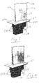
- Figure 2 illustrates a gas turbine blade precursor (intermediate component) that includes the aluminum-bearing coating AL and the as-deposited metallic chromium-bearing coating ECR on the airfoil and the root portion, respectively, applied using a method pursuant to another embodiment of the present invention described below that overcomes problems and difficulties that can be otherwise associated with providing a duplex coating based on needed coating functionality as described in the COMPARISON EXAMPLE set forth below.
- the chromium coating is applied as a very thin layer having a thickness of 0.00127 to 0.127 mm (0.00005 to 0.005 inch).
- the aluminum-bearing coating is applied in a first one step procedure by high temperature vapor deposition, such as by chemical vapor deposition at or above 1038 °C (1900 degrees F) pursuant to US Patent Nos. 5,264,245 ; 4,132,816 ; and 3,486,927 , by conventional above-the-pack processes, or other vapor deposition processes.
- high temperature vapor deposition such as by chemical vapor deposition at or above 1038 °C (1900 degrees F) pursuant to US Patent Nos. 5,264,245 ; 4,132,816 ; and 3,486,927 , by conventional above-the-pack processes, or other vapor deposition processes.
- the chromium-bearing coating is applied after the aluminum-bearing coating using a two step procedure that involves depositing a metallic coating comprising chromium on the substrate at a relatively low temperature below 100 °C (212 degrees F) when a liquid electrolytic deposition bath or liquid carrier medium is employed followed by a high temperature heat treatment to diffuse chromium into the substrate.
- exemplary low temperature processes for depositing the metallic chromium coating include, but are not limited to, electroplating or electrophoetric deposition using a liquid bath, and slurry coating with chromium-bearing particles (e.g.
- Cr or Cr alloy particles in a liquid carrier followed by drying, all of which can be conducted below 100 °C (212 degrees F) using liquid baths or liquid slurries.
- Certain other relatively low temperature deposition processes can be employed to deposit the metallic coating comprising chromium including, but not limited to, electro-spark discharge conducted typically at less than 260 °C (500 degrees F), cladding conducted typically at less than 38 °C (100 degrees F), plasma spray conducted at less than 260 °C (500 degrees F), and entrapment plating wherein Cr particles are entrapped in a Ni electroplated layer.
- a method embodiment is practiced by first applying a mask on a root region of the component, then applying an aluminum-bearing coating, such as a diffusion aluminide coating, on an airfoil region, de-masking the root portion, and then masking on the already-coated airfoil region. Then, this method embodiment deposits a metallic coating comprising chromium on at least a portion of a relatively lower temperature root region that will be subject to hot corrosion, de-masks the airfoil region, followed by diffusing the chromium into the alloy at the coated portion of the root region to form a chromium-enriched surface coating on the portion of the root region.
- an aluminum-bearing coating such as a diffusion aluminide coating
- the aluminum-bearing coating optionally can be applied to cover the airfoil region and also an intermediate platform region and root shank region.
- An attachment portion, such as a fir tree portion, of the root region may be left uncoated to enhance fatigue life of the root region where it is connected to a turbine disk.
- the chromium-enriched diffused coating applied on at least a portion of the root region of a nickel base superalloy substrate typically comprises in the diffused condition a Cr-enriched outermost diffusion zone comprising chromium, nickel, and other substrate alloy elements in solid solution wherein Cr is present as a majority of the zone, Figures 7 and 11A, 11B and inner diffusion zone between the outermost diffusion zone and the substrate and comprising nickel, chromium, and other substrate alloy elements wherein Cr is a minority of the zone, Figures 7 , 11A, 11B .
- Another diffusion or reaction zone may be present between the inner diffusion zone and substrate and comprise refractory rich phases. This diffusion or reaction zone is very thin and is not visible in Figures 7 and 11A .
- This Comparison Example is offered to help illustrate the problems and difficulties of forming such a duplex coating on a gas turbine blade by processing other than that pursuant to the present invention.
- vapor phase chromizing processes can be used to produce a turbine blade with two environmental protection coatings (duplex coating).
- problems in processing and retaining high surface Cr have been observed.
- the masking used for aluminizing can remove Cr from the chromized shank during the high temperature aluminizing process.
- the turbine blade in order to coat a turbine blade with the duplex coating, the turbine blade must be entirely chromized by a high temperature pack or vapor phase process and then the resulting Cr-rich layer must be removed from the gas path surfaces 12, 20a prior to aluminizing or overcoating the gas path surfaces.
- the root region is masked by placing it in masking powder (e.g. alumina powder, NiO powder, etc.) residing in a containment box.
- masking powder e.g. alumina powder, NiO powder, etc.
- a cast turbine blade having airfoil, platform, and root features of Figure 1 and made of CMSX-4 nickel based superalloy (nominal composition in weight % of about 9.6% Co, about 6.6% Cr, about 0.60 % Mo, about 6.4% W, about 3.0% Re, about 6.5% Ta, about 5.6% Al, about 1.0% Ti, about 0.1% Hf, balance Ni and incidental impurities) was chromized all over and then grit blasted to remove the Cr-enriched coating from the first hotter region that included the airfoil region 12 and platform surface 20a.
- the first hotter region was electroplated to deposit a Pt metal layer and then aluminized by CVD to form a Pt-modified diffusion aluminide coating on the first region.
- the second cooler region (that included the platform surface 20b and root region 14) was then masked with commercially available powder maskant M1 available from Akron Paint & Varnish Co., 1390 Firestone Parkway, Akron Ohio.
- the chromizing process was conducted using the following pack parameters: pure chromium powder with aluminum oxide and NH 4 Cl activator for 5 hours at 1066 °C (1950 degrees F).
- the Pt electroplating was conducted using the following parameters set forth in US Patent 5,788,823 , which is incorporated herein by reference to this end, to deposit 0.3 mils of Pt on the substrate.
- the aluminizing process was conducted using the following parameters: 1079 °C (1975 degrees F) for 1440 minutes in H 2/ AlCl 3 atmosphere pursuant to US Patent 5,264,245 , which is incorporated herein by reference to this end.
- Figure 5 shows concentration depth profiles of Cr at the shank portion 18 of the turbine blade for the as-chromized condition (Pack Cr) and after masking and aluminizing (Pack Cr + Aluminizing Cycle) to form the Pt-modified diffusion aluminide coating on the first region that included the airfoil and platform surface 20a.
- the enriched Cr content of the as-chromized coating on the second region as shown in Figure 5 is a desirable chemistry for resisting hot corrosion attack.
- the Cr enrichment formed by the pack chromizing process is depleted following the aluminizing process even when masking is present on the root (shank 18 and attachment portion 16 to prevent aluminum from depositing thereon).
- the Cr content at the shank portion has been is lowered to below the CMSX-4 superalloy content (nominal alloy Cr composition: 6.4% Cr by weight and is directionally exactly the opposite Cr content desired to improve hot corrosion resistance. It is apparent that the duplex coating processing of this Comparison Example failed to produce a turbine blade with a desired Cr-enriched coating for hot corrosion attack resistance.
- the duplex coating is applied using a sequence processing steps that overcomes the above-discussed problems and difficulties demonstrated in the Comparison Example.
- the chromium electroplating process is conducted using plating conditions to deposit a hexavalent hard, dense chromium electroplate comprising substantially pure Cr that meets AMS (Aerospace Material Specification) 2438B for hard, dense chromium coatings for aerospace material applications on steel materials.
- AMS 2338B is incorporated herein by reference to this end.
- the hard, dense substantially pure chromium electroplate was applied commercially by a commercial electroplater Armoloy of Illinois, 118 Simonds Ave., DeKalb, Illinois, using proprietary plating conditions.
- the deposited Cr electroplating was applied to a thickness of 8.7 micrometers or 3.5 micrometers.
- the electroplated layer was substantially pure Cr; e.g. 99.9% by weight pure Cr and balance plating impurities.
- the chromium electroplating can be conducted using any suitable parameters.
- the following plating conditions can be used:
- the CVD aluminizing process is conducted using the following parameters: 1079 °C (1975 degrees F) for 1440 minutes in H 2/ AlCl 3 atmosphere pursuant to US Patent 5,264,245 , which is incorporated herein by reference to this end.
- Other aluminizing processes which can be used include, but are not limited to, pack, vapor phase, sputtering, physical vapor deposition and slurry followed by diffusion heat treatment, electrophoretic followed by diffusion heat treatment, and others.
- the diffusion heat treatment of Cr was conducted at 1079 °C (1975 degrees F) for 4 hours in an Ar partial pressure atmosphere or at 1121 °C (2050 degrees F) for 2 hours in an Ar partial pressure atmosphere to prevent oxidation.
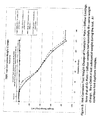
- Figure 6 is graph of Cr concentration versus distance into the CMSX-4 nickel base superalloy substrate showing effects of Cr plating thickness and diffusion conditions on Cr concentration in the substrate.
- the distance of "0" is the surface of the substrate.
- Figure 6 shows that the surface Cr content can be controlled to be as low as 15 weight % or as high as 63 weight %.
- Figure 6 shows that the depth of Cr enrichment can be controlled as well. Typically, the Cr content and enrichment depth can be balanced to provide acceptable hot corrosion resistance while minimizing fatigue debit for the strains to be experienced by the component in use in the turbine engine.
- Figure 6 presents two Cr plating thicknesses and two different diffusion heat treatments illustrating a range of resultant Cr enrichments.
- Figures 7 and 11A contain photomicrographs of the microstructure of a CMSX-4 specimen electroplated with 8.7 ⁇ m of Cr plating followed by a diffusion treatment by heating at 1079 °C (1975 degrees F) for four hours.
- Figure 11B includes microprobe data of the Cr-enriched diffused coating as a table and
- Figure 11C includes a plot showing variation of Cr content over distance into the substrate alloy. The distance of "0" is the surface of the substrate.
- Figures 7 and 11A, 11B (microprobe table) and 11C (plot) results reveal that the chromium-enriched diffused coating comprised a Cr-enriched outermost (Top) diffusion zone comprising chromium, nickel, and other substrate alloy elements in solid solution wherein Cr is present as a majority of the Top zone and inner diffusion zone (Diffusion) between the outermost diffusion zone and the substrate and comprising nickel, chromium, and other substrate alloy elements wherein Cr is a minority of the Diffusion zone.
- Another diffusion or reaction zone may be present between the inner diffusion zone and the substrate and comprise refractory rich phases. This diffusion or reaction zone is very thin and is not visible in Figures 7 and 11A .
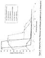
- Figure 8 illustrates hot corrosion test results at 700 degrees C plotted as weight change versus exposure hours for the various CMSX-4 specimens shown, which were tested in duplicate.
- the test applied 1-2 mg/cm 2 of Na 2 SO 4 to the specimen surface at each 20 hour specimen inspection and then exposed the salted sample to 371 °C (700 degrees F) in a furnace which had a 1000 ppm SO 2 /O 2 gas passing through a heated Pt catalyst to form SO 3 .
- the SO 3 reacted with the salt at the test temperature to provide corrosion attack.
- Figure 8 shows that the tested specimens coated pursuant to embodiments of the invention exhibited essentially the same weight change over time, regardless of the thickness of the Cr electroplate and Cr diffusion parameters employed. Bare (uncoated) CMSX-4 specimen lost substantial weight during the test.
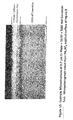
- Figure 9 is a photomicrograph of a CMSX-4 specimen electroplated with 8.7 ⁇ m of Cr plating followed by a diffusion treatment by heating at 1079 °C (1975 degrees F) for four hours and subjected to the above 371 °C (700 degrees F)hot corrosion with Na 2 SO 4 applied to the specimen as in Figure 8 .
- Through-holes (one shown) through the specimen were not coated and show aggressive hot corrosion attack while coated surfaces are protected.
- Figure 9 shows the aggressive nature of these test conditions to the bare (uncoated) CMSX-4 alloy substrate and the resistance of the coated specimen surfaces to hot corrosion attack.
- Figure 10 is a photomicrograph of the microstructure of a CMSX-4 specimen electroplated with 8.7 ⁇ m of Cr plating followed by a diffusion treatment by heating at 1079 °C (1975 degrees F) for four hours and then subjected to hot corrosion at 700 degrees C with Na 2 SO 4 applied to the specimen surface as in Figure 8 .
- Figure 11C is a graphic plot showing variation of Cr content over distance into the substrate alloy for the As-Plated sample (open triangle symbols), plated/diffusion-heat treated sample (open square symbols), and plated/diffusion heat treated/hot corrosion tested sample (open diamond symbols-Type I hot corrosion test). The distance of "0" is the surface of the substrate.
- the chromium electroplating process is conducted by the commercial electroplater of Example 1.
- the CVD aluminizing process is conducted using the parameters of Example 1.
- the diffusion heat treatment of Cr is conducted using the parameters of Example 1.
- Figures 3 and 4 illustrate alternative embodiments of the invention where, in Figure 3 , an aluminized layer AL' with or without Pt is applied on the upper region of the shank portion 18 from the platform surface 20b to a preselected distance or plane below the platform 20 along with other coatings AL, CR as indicated; and where, in Figure 4 , an uncoated attachment portion 17 of the root region is provided at an even cooler region of the turbine blade closer to the turbine disk, which portion 17 is masked during both aluminizing and Cr plating.
- the attachment portion 17 comprises bare (uncoated) substrate alloy where the blade design cannot tolerate any coating along with other coatings AL, CR as indicated.
- the invention allows for many combinations of Al, Al/Cr, Cr, and bare, uncoated areas on a turbine blade to provide desired coating functionality as needed to suit different service conditions in the gas turbine engine.
- the present disclosure relates to a method of forming a coating on a substrate, comprising the steps of first applying an aluminum-bearing coating on a first region of the substrate, then depositing a metallic coating comprising chromium on the substrate, and then diffusing the chromium into the substrate to form a chromium-enriched diffused layer thereon.
- the method according to the first aspect of the present disclosure may include the additional step of applying masking on said second region before the aluminum-bearing coating is applied.
- the method according to the first aspect of the present disclosure may include the additional step of applying masking on the aluminum-bearing coating before applying the metallic coating.
- the method according to the first aspect of the present disclosure may include the additional step of applying the aluminum-bearing coating on both said first region and second region followed by removal of the aluminum-bearing coating from said adjacent region before the metallic coating is applied.
- the metallic coating may be applied by using a liquid deposition medium.
- This liquid deposition medium is preferably a electroplating bath or electrophoretic bath, or a slurry of chromium-bearing particles.
- the aluminum-bearing coating may be applied as a diffusion aluminide.
- the present disclosure relates to a method of forming a duplex coating on a nickel or cobalt based alloy turbine blade, comprising the steps of first applying an aluminum-bearing coating on an airfoil region of the blade, then depositing a metallic coating comprising chromium on at least a portion of a root region of the blade using a liquid deposition medium, and then diffusing the chromium into the alloy to form a chromium-enriched layer on said portion of said root region.
- the method according to the second aspect of the present disclosure may include the additional step of applying masking on the root region before the aluminum-bearing coating is applied on the airfoil region.
- the method according to the second aspect of the present disclosure may include the additional step of applying the aluminum-bearing coating on the airfoil region and on the root region followed by removal of the aluminum-bearing coating from the root region before the metallic overlay is applied to the root region.
- the method according to the second aspect of the present disclosure may include the additional step of applying masking on the aluminum-bearing coating before applying the metallic coating.
- the metallic coating may be electroplated at a temperature less than 100°C (212 degrees F).
- the aluminum-bearing coating may be applied to also cover a shank portion of said root region such that the root region includes the shank portion covered by the aluminum-bearing coating and an adjacent portion covered by the chromium-enriched coating.
- the method according to the second aspect of the present disclosure may include the additional step of leaving an attachment portion of the root region uncoated.
- the aluminum-bearing coating may be applied as a diffusion aluminide.
- the liquid deposition medium may be an electroplating bath or electrophoretic bath.
- the liquid deposition medium may be a slurry of chromium-bearing particles.
- the present disclosure relates to a nickel or cobalt based alloy turbine component precursor having an aluminum-bearing coating applied on an airfoil region of the precursor and a metallic electroplated or electrophoretic coating comprising chromium applied on at least a portion of a root region of the precursor.
- the metallic coating may comprise a majority of chromium.
- the aluminum-bearing coating may also cover a shank portion of said root region such that the root region includes a shank portion covered by the aluminum-bearing coating and an adjacent portion covered by the metallic coating.
- an attachment portion of the root region may left uncoated.
- the aluminum-bearing coating may comprise a diffusion aluminide.
- the precursor may include a platform region between the airfoil region and the root region, wherein a surface of the platform facing toward the airfoil region includes the aluminum-bearing coating.
- a surface of the platform region facing away from the airfoil region preferably includes the metallic coating.
- a surface of the platform region facing away from the airfoil region may include the aluminum-bearing coating.
- the present disclosure relates to a nickel or cobalt based alloy turbine component precursor having an aluminum-bearing coating applied on an airfoil region of the precursor and a metallic coating comprising chromium-bearing slurry particles applied on at least a portion of a root region of the precursor.
- the present disclosure relates to a nickel or cobalt based alloy turbine component having an aluminum-bearing coating applied on an airfoil region of the blade and a chromium-enriched coating formed on at least a portion of a root region by depositing a metallic electroplated or electrophoretic coating comprising chromium and diffusing the chromium into the alloy at said portion of said root region.
- the component may include a platform region between the airfoil region and the root region, wherein a surface of the platform facing toward the airfoil region includes the aluminum-bearing coating.
- a surface of the platform region facing away from the airfoil region preferably includes the chromium-bearing coating.
- the surface of the platform region facing toward the airfoil region may include the aluminum-bearing coating, wherein the aluminum-bearing coating preferably comprises a diffusion aluminide, and/or wherein the aluminum-bearing coating also covers a shank portion of said root region such that the root region includes a shank portion covered by the aluminum-bearing coating and an adjacent portion covered by the chromium-enriched coating.
- the an attachment portion of the root region is uncoated.
- the present disclosure relates to a nickel or cobalt based alloy turbine component having an aluminum-bearing coating applied on an airfoil region of the blade and a chromium-enriched coating formed on at least a portion of a root region by depositing a metallic coating comprising chromium-bearing slurry particles and diffusing the chromium into the alloy at said portion of said root region.
Abstract
Description
- The present invention relates to a protective coating for a gas turbine blade or other component wherein the coating includes an aluminum-bearing coating applied at a relatively high temperature region of the component and a chromium-bearing coating applied at another relatively lower temperature region of the component depending on coating functionality needed.
- Current gas turbine designs are requiring that a variety of coatings be applied to different areas of the turbine part for different functional reasons. Examples of coating functionality include wear, oxidation, thermal barrier, and hot corrosion. Turbine designers choose an appropriate coating for a particular functionality in the gas turbine environment.
- Hot corrosion is a form of accelerated oxidation when a liquid salt is present on the surface of a Ni and Co based superalloy component. The salt is usually sodium sulfate with other naturally occurring constituents, such as K, Ca, and/or Mg, present. It is well known that as the Cr content of an alloy increases, its resistance to hot corrosion attack increases. Current methods to increase surface Cr content are pack and vapor phase chromizing, which comprise one-step deposition and reaction with the Ni substrate alloy, forming a Cr-enriched alloy zone. The chromizing process is facilitated by halide (Cl or F) activators that form Cr-halide gases at relatively high temperatures, such as greater than 1038 °C (1900 degrees F).
- Since pack and vapor phase chromizing require high temperature application above 1038 °C (1900 degrees F) and are difficult to apply to localized part areas of interest, these processes must be applied early in the part routing to the entire the part. Masking has not been effective in these processes as a means for controlling the localized deposition of the chromium on certain areas of interest and, as a result, has not been applied in these high temperature processes.
- The present invention provides in an embodiment a method of forming a protective coating on a gas turbine component wherein the duplex coating includes an aluminum-bearing coating applied at one region of the gas turbine component where relatively higher temperatures are encountered in service and a chromium-bearing coating applied at another region of the turbine blade or other component where relatively lower temperatures and hot corrosion are encountered in service, thereby providing coating functionality for the different temperatures and oxidation/corrosion environments to be encountered by the gas turbine component.
- In an illustrative embodiment of the present invention, the method involves forming a duplex coating on a superalloy substrate by first applying an aluminum-bearing coating on the first relatively higher temperature region of the substrate, secondly applying a metallic coating comprising chromium on an adjacent relatively lower temperature region of the substrate followed by diffusing chromium into the substrate to form a chromium-enriched diffused coating thereon at the adjacent relatively lower temperature region. The aluminum-bearing coating is applied in a first step by high temperature vapor deposition, while the chromium-bearing coating is applied in a subsequent second step at a relatively lower temperature, such as less than 260 °C (500 degrees F). The method typically involves applying masking on the relatively lower temperature region before the aluminum-bearing coating is applied on the relatively higher temperature region and subsequently applying masking on the relatively higher temperature region before the metallic coating of chromium is applied on the relatively lower temperature region.
- In the event the substrate is a gas turbine component, the method is practiced by first applying a mask on a root region of the component, then applying an aluminum-bearing coating, such as a diffusion aluminide coating, on an airfoil region, de-masking the root portion, and then masking the already-coated airfoil region. Then, the method involves depositing a metallic coating comprising chromium on at least a portion of a relatively lower temperature root region that will be subject to hot corrosion, de-masking the airfoil region followed by diffusing the chromium into the alloy at the coated portion of the root region to form a chromium-enriched diffused surface coating on the portion of the root region. The aluminum-bearing coating optionally can be applied to cover the airfoil region and also an intermediate platform region and root shank region. An attachment portion, such as a fir tree portion, of the root region may be left uncoated to enhance fatigue life of the root region where it is connected to a turbine disk.
- In a particular embodiment of the present invention, a relatively low temperature deposition process embodying a liquid deposition medium, such as electroplating bath, electrophoretic bath, liquid slurry, and others, is used to form a metallic coating comprising a majority of chromium on at least a portion of the relatively lower temperature region of a precursor component. The chromium coating is applied as a very thin layer having a thickness of 0.00127 to 0.127 mm (0.00005 to 0.005 inch). Diffusion of the as-deposited chromium into the substrate typically is effected by elevated temperature heat treatment after the masking is removed from the previously-applied aluminum-bearing coating on the airfoil region.
- The present invention envisions a nickel or cobalt based alloy turbine component precursor having an aluminum-bearing coating applied on an airfoil region and metallic coating comprising substantially pure chromium or a chromium alloy applied on at least a portion of the root region of the component. The chromium coating then is diffused into the alloy to form a diffused chromium-enriched coating on the portion of the root region of the gas turbine blade. The diffused chromium-enriched coating has an outermost region that comprises at least about 20%, preferably about 25%, and more preferably about 30% to about 60% by weight Cr.
- Advantages, features, and embodiments of the present invention will become apparent from the following description.
-
-
Figure 1 is a schematic view of a gas turbine blade having an aluminum-bearing coating AL on the airfoil region and on the platform region surface facing the hot gas path in order to form a protective alumina scale or layer in service and having a diffused chromium-enriched coating CR on the root region and on the platform region facing away from the hot gas path in order to form a protective chromia scale or layer in service. -
Figure 2 is a schematic view of an intermediate gas turbine blade precursor having an aluminum-bearing coating AL on the airfoil region and on the platform region surface facing the hot gas path to form a protective alumina scale or layer in service and having a metallic chromium coating ECR on the root region and on the platform region facing away from the hot gas path in order to be diffused into the alloy to form a protective diffused chromium-enriched coating. -
Figures 3 and 4 are further schematic views of other embodiments of a gas turbine blade where the aluminum-bearing coating and the chromium-bearing coating reside on various illustrative regions of the turbine blade. -
Figure 5 is a graph of chromium concentration profiles (Cr concentration versus distance into the CMSX-4 nickel base superalloy substrate) at a shank portion of the root region after pack chromizing and after masking the shank region and aluminizing to form a Pt-modified diffusion aluminide (Pt-Al) coating on the airfoil. The root region includes the shank portion and the fir tree attachment portion of the turbine blade. -
Figure 6 is graph of Cr concentration versus distance into the CMSX-4 nickel base superalloy substrate showing effects of Cr plating thickness and diffusion conditions on Cr concentration in the substrate. The distance of "0" is the surface of the substrate. -
Figure 7 is a photomicrograph of the microstructure of a CMSX-4 specimen electroplated with 8.7 µm of Cr plating followed by a diffusion treatment by heating at 1079 °C (1975 degrees F) for four hours. -
Figure 8 shows hot corrosion test results at 700 degrees C plotted as weight change versus exposure hours for the various CMSX-4 specimens shown, which were tested in duplicate. The test involved applying 1-2 mg/cm2 to the specimen surface at each 25 hour specimen inspection. -
Figure 9 is a photomicrograph of a CMSX-4 specimen electroplated with 8.7 µm of Cr plating followed by a diffusion treatment by heating at 1079 °C (1975 degrees F) for four hours and subjected to hot corrosion with Na2SO4 applied to the specimen surface as inFigure 8 . Through-holes (one shown) through the specimen were not coated and show aggressive hot corrosion attack while coated surfaces are protected. -
Figure 10 is a photomicrograph of the microstructure of a CMSX-4 specimen electroplated with 8.7 µm of Cr plating followed by a diffusion treatment by heating at 1079 °C (1975 degrees F) for four hours and then subjected to hot corrosion at 700 degrees C with Na2SO4 applied to the specimen surface as inFigure 8 . -
Figure 11A is photomicrograph of a CMSX-4 specimen electroplated with 8.7 µm of Cr plating followed by a diffusion treatment by heating at 1079 °C (1975 degrees F) for four hours.Figure 11B shows microprobe results as a table for specimen ofFig. 11A. Figure 11C is a graphic plot showing variation of Cr content over distance into the substrate alloy for the As-Plated sample (open triangle symbols), plated/diffusion-heat treated sample (open square symbols), and plated/diffusion heat treated/hot corrosion tested sample (open diamond symbols-Type I hot corrosion test). The distance of "0" is the surface of the substrate. - In one embodiment of the present invention, a method is provided for forming a protective coating on a gas turbine component wherein the coating includes an aluminum-bearing coating applied at one region of the turbine blade or other component where relatively higher temperatures are encountered in service and a chromium-bearing coating formed at another adjacent region of the component where relatively lower temperatures and hot corrosion are encountered in service. Such a duplex coating provides coating functionality for the different temperatures and oxidation/corrosion environments to be encountered in service.
- The present invention is especially useful for protecting different regions of a gas turbine blade component from oxidation and hot corrosion in service in a gas turbine engine, although the invention is not limited to gas turbine components since it can be practiced to protect other components against oxidation and hot corrosion. The present invention can be practiced to protect nickel based superalloy gas turbine components, nickel-cobalt based superalloy gas turbine components, or cobalt based superalloy gas turbine components from hot corrosion, although the invention is not limited to these alloys. For purposes of illustration and not limitation, the present invention will be described below with respect to protection of different regions of a gas turbine engine blade made of CMSX-4 nickel based superalloy against oxidation and hot corrosion in service in a gas turbine engine.
- In particular,
Figure 1 shows an exemplarygas turbine blade 10 having anairfoil region 12, aroot region 14 and anintermediate platform region 20 between the airfoil and root regions. Theairfoil 12 includes atip 12a, a leading edge 12b, and trailing edge 12c subjected to the gas path of the engine turbine section. Aplatform region 20 typically separates the gas-path surfaces from non-gas path surfaces and includes an upper platform surface facing the gas path and an lower platform surface facing away from the gas path. Theroot region 14 includes non-gas path surfaces beneath the lower side of theplatform region 20 wherein the root region includes a anattachment portion 16, such as a conventional fir tree portion, by which the turbine blade is connected to the turbine disk (not shown) in usual manner and anadjacent shank portion 18 between theattachment portion 16 and theplatform region 20. The fir tree typically comprises machined serrations which fit into the turbine disk and which can be machined before or after coating pursuant to customer specifications. Theshank region 18 includes the region between the fir tree and lower side of theplatform region 20 and may include as-cast and machined surfaces as well as features to aid sealing the gas path from the non-gas path regions. - A first hotter region of the
turbine blade 10 is subjected to relatively higher temperatures and oxidation degradation in service in the gas turbine engine and comprises theairfoil region 12 and surface 20a of aplatform region 20 that faces toward the airfoil region such that theairfoil region 12 and platform surface 20a operate in or near the hot gas path of the turbine section of the gas turbine engine. Theairfoil region 12 and platform surface 20a are the hottest regions of the turbine blade and usually operate above 1038 °C (1900 degrees F) for purposes of illustration and not limitation. - As a result of the relatively high operating temperatures encountered, the
airfoil region 12 and the platform surface 20a preferably are provided with a so-called alumina-former coating thereon that produces an adherent protective scale of alumina in service in the gas turbine engine. - A second relatively cooler region of the
turbine blade 10 is subjected to relatively lower temperatures and hot corrosion by salts, such as sodium sulfates and other constituents such as K, Ca, and/or Mg, in service in the gas turbine engine. The second region comprises the under (lower) surface 20b of aplatform region 20 that faces away from theairfoil region 12 and theroot region 14. The second region thus involves a cooler region that on older turbine blades may operate uncoated. However, as the combustor efficiency has improved, the operating temperature of the second region is generally increasing and spread more uniformly over the second region. Hence the first region comprised of theairfoil 12 and platform surface surface 20a is also becoming hotter. When salts of sodium sulphate are deposited on a surface that operates between 49 °C (120 degrees F) and 1010 °C (1850 degrees F), hot corrosion attack can occur. Combining the high stress state of theblade root 14, with hot corrosion conditions, rapid attack and fracture of the turbine blade in the root region can occur. For turbine blades with uncoated root regions heretofore used in the lower temperature operating conditions, hot corrosion resistance can be increased by increasing the chromium content of the turbine blade alloy. - The present invention provides a multiplex coating and a method for applying the coating to protect the different hotter and cooler regions of the turbine blade exposed to more aggressive temperature/hot corrosion conditions associated recent engine designs. The present invention provides a nickel or cobalt based
alloy turbine blade 10 having an aluminum-bearing coating AL applied on an airfoil region of the blade and a metallic coating comprising chromium applied on at least a portion of the root region of the blade and diffused into the alloy to form the diffused chromium-enriched coating CR on the portion of the root region.Figure 1 illustrates the aluminum-bearing coating AL and the chromium-bearing diffused coating CR on the airfoil and the root portion, respectively. The aluminum-bearing coating AL comprises a so-called alumina-forming coating in that it forms a thin adherent alumina scale on the coating in service. The chromium-bearing diffused coating CR comprises a so-called chromia-forming coating in that it forms a thin adherent chromia scale on the coating in service. Also, after or before the diffusion of the chromium coating, a thermal barrier coating (TBC), such as yttria-stablized zirconia, can be applied as an outermost coating to all or portion ofairfoil region 12 and platform surface 20a to provide thermal insulation properties of the TBC. -
Figure 2 illustrates a gas turbine blade precursor (intermediate component) that includes the aluminum-bearing coating AL and the as-deposited metallic chromium-bearing coating ECR on the airfoil and the root portion, respectively, applied using a method pursuant to another embodiment of the present invention described below that overcomes problems and difficulties that can be otherwise associated with providing a duplex coating based on needed coating functionality as described in the COMPARISON EXAMPLE set forth below. The chromium coating is applied as a very thin layer having a thickness of 0.00127 to 0.127 mm (0.00005 to 0.005 inch). - The aluminum-bearing coating is applied in a first one step procedure by high temperature vapor deposition, such as by chemical vapor deposition at or above 1038 °C (1900 degrees F) pursuant to
US Patent Nos. 5,264,245 ;4,132,816 ; and3,486,927 , by conventional above-the-pack processes, or other vapor deposition processes. - The chromium-bearing coating is applied after the aluminum-bearing coating using a two step procedure that involves depositing a metallic coating comprising chromium on the substrate at a relatively low temperature below 100 °C (212 degrees F) when a liquid electrolytic deposition bath or liquid carrier medium is employed followed by a high temperature heat treatment to diffuse chromium into the substrate. Exemplary low temperature processes for depositing the metallic chromium coating include, but are not limited to, electroplating or electrophoetric deposition using a liquid bath, and slurry coating with chromium-bearing particles (e.g. Cr or Cr alloy particles) in a liquid carrier followed by drying, all of which can be conducted below 100 °C (212 degrees F) using liquid baths or liquid slurries. Certain other relatively low temperature deposition processes can be employed to deposit the metallic coating comprising chromium including, but not limited to, electro-spark discharge conducted typically at less than 260 °C (500 degrees F), cladding conducted typically at less than 38 °C (100 degrees F), plasma spray conducted at less than 260 °C (500 degrees F), and entrapment plating wherein Cr particles are entrapped in a Ni electroplated layer.
- When the substrate comprises a gas turbine component having airfoil, platform and root regions, a method embodiment is practiced by first applying a mask on a root region of the component, then applying an aluminum-bearing coating, such as a diffusion aluminide coating, on an airfoil region, de-masking the root portion, and then masking on the already-coated airfoil region. Then, this method embodiment deposits a metallic coating comprising chromium on at least a portion of a relatively lower temperature root region that will be subject to hot corrosion, de-masks the airfoil region, followed by diffusing the chromium into the alloy at the coated portion of the root region to form a chromium-enriched surface coating on the portion of the root region. The aluminum-bearing coating optionally can be applied to cover the airfoil region and also an intermediate platform region and root shank region. An attachment portion, such as a fir tree portion, of the root region may be left uncoated to enhance fatigue life of the root region where it is connected to a turbine disk.
- The chromium-enriched diffused coating applied on at least a portion of the root region of a nickel base superalloy substrate typically comprises in the diffused condition a Cr-enriched outermost diffusion zone comprising chromium, nickel, and other substrate alloy elements in solid solution wherein Cr is present as a majority of the zone,
Figures 7 and11A, 11B and inner diffusion zone between the outermost diffusion zone and the substrate and comprising nickel, chromium, and other substrate alloy elements wherein Cr is a minority of the zone,Figures 7 ,11A, 11B . Another diffusion or reaction zone may be present between the inner diffusion zone and substrate and comprise refractory rich phases. This diffusion or reaction zone is very thin and is not visible inFigures 7 and11A . - Practice of embodiments of the invention allow control of the Cr content and Cr depth profile into the substrate to tailor hot corrosion protection as needed for a particular service application. Typically, more Cr at the outermost coated substrate surface will be more protective than less. More Cr can be provided by varying the thickness of the Cr metallic coating and the diffusion heat treatment conditions.
- This Comparison Example is offered to help illustrate the problems and difficulties of forming such a duplex coating on a gas turbine blade by processing other than that pursuant to the present invention.
- For example, available high temperature (above 1038 °C (1900 degrees F)) pack or vapor phase chromizing processes and high temperature (above 927 °C (1700 degrees F)) pack, vapor phase or CVD aluminizing processes can be used to produce a turbine blade with two environmental protection coatings (duplex coating). However problems in processing and retaining high surface Cr have been observed. The masking used for aluminizing can remove Cr from the chromized shank during the high temperature aluminizing process. Namely, in order to coat a turbine blade with the duplex coating, the turbine blade must be entirely chromized by a high temperature pack or vapor phase process and then the resulting Cr-rich layer must be removed from the gas path surfaces 12, 20a prior to aluminizing or overcoating the gas path surfaces. To prevent aluminizing of the
root region 14, the root region is masked by placing it in masking powder (e.g. alumina powder, NiO powder, etc.) residing in a containment box. However, this procedure has resulted in unwanted reductions in Cr content of the previously applied Cr-enriched layer on the root region and a reduction in its hot corrosion resistance as will now be demonstrated. - A cast turbine blade having airfoil, platform, and root features of
Figure 1 and made of CMSX-4 nickel based superalloy (nominal composition in weight % of about 9.6% Co, about 6.6% Cr, about 0.60 % Mo, about 6.4% W, about 3.0% Re, about 6.5% Ta, about 5.6% Al, about 1.0% Ti, about 0.1% Hf, balance Ni and incidental impurities) was chromized all over and then grit blasted to remove the Cr-enriched coating from the first hotter region that included theairfoil region 12 and platform surface 20a. The first hotter region was electroplated to deposit a Pt metal layer and then aluminized by CVD to form a Pt-modified diffusion aluminide coating on the first region. The second cooler region (that included the platform surface 20b and root region 14) was then masked with commercially available powder maskant M1 available from Akron Paint & Varnish Co., 1390 Firestone Parkway, Akron Ohio. - The chromizing process was conducted using the following pack parameters: pure chromium powder with aluminum oxide and NH4Cl activator for 5 hours at 1066 °C (1950 degrees F).
- The Pt electroplating was conducted using the following parameters set forth in
US Patent 5,788,823 , which is incorporated herein by reference to this end, to deposit 0.3 mils of Pt on the substrate. The aluminizing process was conducted using the following parameters: 1079 °C (1975 degrees F) for 1440 minutes in H2/AlCl3 atmosphere pursuant toUS Patent 5,264,245 , which is incorporated herein by reference to this end. -
Figure 5 shows concentration depth profiles of Cr at theshank portion 18 of the turbine blade for the as-chromized condition (Pack Cr) and after masking and aluminizing (Pack Cr + Aluminizing Cycle) to form the Pt-modified diffusion aluminide coating on the first region that included the airfoil and platform surface 20a. - The enriched Cr content of the as-chromized coating on the second region as shown in
Figure 5 is a desirable chemistry for resisting hot corrosion attack. However, as the graph shows, the Cr enrichment formed by the pack chromizing process is depleted following the aluminizing process even when masking is present on the root (shank 18 andattachment portion 16 to prevent aluminum from depositing thereon). The Cr content at the shank portion has been is lowered to below the CMSX-4 superalloy content (nominal alloy Cr composition: 6.4% Cr by weight and is directionally exactly the opposite Cr content desired to improve hot corrosion resistance. It is apparent that the duplex coating processing of this Comparison Example failed to produce a turbine blade with a desired Cr-enriched coating for hot corrosion attack resistance. - Pursuant to method embodiments of the present invention, the duplex coating is applied using a sequence processing steps that overcomes the above-discussed problems and difficulties demonstrated in the Comparison Example.
- Pursuant to an illustrative embodiment of the present invention, the following processing steps are employed:
- 1. If a platinum-modified diffusion aluminide coating is to be formed on the gas path surfaces 12, 20a, then these surfaces are optionally electroplated with a layer of Pt pursuant to
US Patent 5,788,832 which is already incorporated herein by reference. If a simple diffusion aluminde coating is to be formed, then this step is omitted. - 2. Masking the second region of the turbine blade (i.e.
root region 14 and platform surface 20b) with the M1 maskant powder mentioned above in a containment box. That is, theroot region 14 and platform surface 20b are embedded in the maskant powder in the containment box. - 3. Aluminize the first hotter region (i.e. airfoil 12 and platform surface 20a) to form a diffusion aluminide coating, such as a Pt-modified diffusion aluminide coating if
step 1 is practiced, with the masking covering the second region. - 4. Masking the diffusion aluminide coating on the first region.
- 5. Cr electroplating the second cooler region with the masking of
step 2 covering the diffusion aluminide coating formed in step 3. The Cr electroplating is conducted at low temperature such as less than 100 °C (212 degrees F) using a liquid (e.g. aqueous) electroplating bath. The Cr electroplate can be locally deposited by virtue of the masking on the first region being effective under the low temperature plating bath conditions. - 6. Diffusing the Cr plating into the CMSX-4 substrate alloy to form the Cr-enriched hot corrosion resistant coating wherein diffusing of the Cr plating improves bonding with the superalloy substrate and makes the resulting Cr-rich layer more ductile.
- The chromium electroplating process is conducted using plating conditions to deposit a hexavalent hard, dense chromium electroplate comprising substantially pure Cr that meets AMS (Aerospace Material Specification) 2438B for hard, dense chromium coatings for aerospace material applications on steel materials. AMS 2338B is incorporated herein by reference to this end.
- In this example, the hard, dense substantially pure chromium electroplate was applied commercially by a commercial electroplater Armoloy of Illinois, 118 Simonds Ave., DeKalb, Illinois, using proprietary plating conditions. The deposited Cr electroplating was applied to a thickness of 8.7 micrometers or 3.5 micrometers. The electroplated layer was substantially pure Cr; e.g. 99.9% by weight pure Cr and balance plating impurities. The invention envisions electroplating Cr alloys, rather than pure Cr, and also plating alternating layers of Cr and Ni.
- The chromium electroplating can be conducted using any suitable parameters. For purposes of illustration and not limitation, the following plating conditions can be used:
- 1. Vapor hone surfaces with an alumina slurry to clean surfaces to be plated.
- 2. Activate the surfaces to be plated by immersion in plating bath containing 250-400 g/L chromic acid and 2.5-4 g/L of sulfate catalyst (sulfuric acid) at 52-63°C and applying a current (30-54 A/dm2 at 3 to 12 volts) such that the parts are anodes (which is opposite of Cr plate deposition) for 30 seconds to 2 minutes.
- 3. Cr plate surfaces to be plated by immersion in plating bath and applying current (such that the parts are cathodes) for 4 minutes to 30 minutes or as long as needed to meet the thickness requirement for the Cr plating.
- 4. Rinse in 49 °C (120 degrees F)de-ionized water to remove majority of plating bath.
- 5. Rinse in hot de-ionized water to remove remaining plating bath and dry.
- The CVD aluminizing process is conducted using the following parameters: 1079 °C (1975 degrees F) for 1440 minutes in H2/AlCl3 atmosphere pursuant to
US Patent 5,264,245 , which is incorporated herein by reference to this end. Other aluminizing processes which can be used include, but are not limited to, pack, vapor phase, sputtering, physical vapor deposition and slurry followed by diffusion heat treatment, electrophoretic followed by diffusion heat treatment, and others. - For this example, the diffusion heat treatment of Cr was conducted at 1079 °C (1975 degrees F) for 4 hours in an Ar partial pressure atmosphere or at 1121 °C (2050 degrees F) for 2 hours in an Ar partial pressure atmosphere to prevent oxidation.
-
Figure 6 is graph of Cr concentration versus distance into the CMSX-4 nickel base superalloy substrate showing effects of Cr plating thickness and diffusion conditions on Cr concentration in the substrate. InFigure 6 , the distance of "0" is the surface of the substrate.Figure 6 shows that the surface Cr content can be controlled to be as low as 15 weight % or as high as 63 weight %. Also,Figure 6 shows that the depth of Cr enrichment can be controlled as well. Typically, the Cr content and enrichment depth can be balanced to provide acceptable hot corrosion resistance while minimizing fatigue debit for the strains to be experienced by the component in use in the turbine engine.Figure 6 presents two Cr plating thicknesses and two different diffusion heat treatments illustrating a range of resultant Cr enrichments. -
Figures 7 and11A contain photomicrographs of the microstructure of a CMSX-4 specimen electroplated with 8.7 µm of Cr plating followed by a diffusion treatment by heating at 1079 °C (1975 degrees F) for four hours.Figure 11B includes microprobe data of the Cr-enriched diffused coating as a table andFigure 11C includes a plot showing variation of Cr content over distance into the substrate alloy. The distance of "0" is the surface of the substrate. -
Figures 7 and11A, 11B (microprobe table) and 11C (plot) results reveal that the chromium-enriched diffused coating comprised a Cr-enriched outermost (Top) diffusion zone comprising chromium, nickel, and other substrate alloy elements in solid solution wherein Cr is present as a majority of the Top zone and inner diffusion zone (Diffusion) between the outermost diffusion zone and the substrate and comprising nickel, chromium, and other substrate alloy elements wherein Cr is a minority of the Diffusion zone. Another diffusion or reaction zone may be present between the inner diffusion zone and the substrate and comprise refractory rich phases. This diffusion or reaction zone is very thin and is not visible inFigures 7 and11A . -
Figure 8 illustrates hot corrosion test results at 700 degrees C plotted as weight change versus exposure hours for the various CMSX-4 specimens shown, which were tested in duplicate. The test applied 1-2 mg/cm2 of Na2SO4 to the specimen surface at each 20 hour specimen inspection and then exposed the salted sample to 371 °C (700 degrees F) in a furnace which had a 1000 ppm SO2/O2 gas passing through a heated Pt catalyst to form SO3. The SO3 reacted with the salt at the test temperature to provide corrosion attack. -
Figure 8 shows that the tested specimens coated pursuant to embodiments of the invention exhibited essentially the same weight change over time, regardless of the thickness of the Cr electroplate and Cr diffusion parameters employed. Bare (uncoated) CMSX-4 specimen lost substantial weight during the test. -
Figure 9 is a photomicrograph of a CMSX-4 specimen electroplated with 8.7 µm of Cr plating followed by a diffusion treatment by heating at 1079 °C (1975 degrees F) for four hours and subjected to the above 371 °C (700 degrees F)hot corrosion with Na2SO4 applied to the specimen as inFigure 8 . Through-holes (one shown) through the specimen were not coated and show aggressive hot corrosion attack while coated surfaces are protected. -
Figure 9 shows the aggressive nature of these test conditions to the bare (uncoated) CMSX-4 alloy substrate and the resistance of the coated specimen surfaces to hot corrosion attack. -
Figure 10 is a photomicrograph of the microstructure of a CMSX-4 specimen electroplated with 8.7 µm of Cr plating followed by a diffusion treatment by heating at 1079 °C (1975 degrees F) for four hours and then subjected to hot corrosion at 700 degrees C with Na2SO4 applied to the specimen surface as inFigure 8 . -
Figure 11C is a graphic plot showing variation of Cr content over distance into the substrate alloy for the As-Plated sample (open triangle symbols), plated/diffusion-heat treated sample (open square symbols), and plated/diffusion heat treated/hot corrosion tested sample (open diamond symbols-Type I hot corrosion test). The distance of "0" is the surface of the substrate. - Comparing the later two samples in
Figure 11C , the Cr content after the hot corrosion test is virtually unchanged. - Pursuant to another illustrative embodiment of the present invention, the following processing steps are employed:
- 1. If a platinum-modified diffusion aluminide coating is to be formed on the gas path surfaces 12, 20a, then these surfaces are optionally electroplated with a layer of Pt pursuant to
US Patent 5,788,832 which is already incorporated herein by reference. If a simple diffusion aluminide coating is to be formed, then this step is omitted. - 2. Aluminize the first hotter region and the second region to form a diffusion aluminide coating, such as a Pt-modified diffusion aluminide coating. No masking covering the second region.
- 3. Removing the diffusion aluminide coating selectively from the second region by grit blasting, machining or other technique to expose the substrate alloy, while leaving the diffusion aluminide coating on the first region.
- 4. Masking the diffusion aluminide coating on the first region as described in Example 1.
- 5. Cr electroplating the exposed second cooler region with the masking of
step 4 covering the diffusion aluminide coating formed instep 2. The Cr electroplating is conducted at low temperature such as less than 100 °C (212 degrees F) using a liquid electroplating bath. The Cr electroplate can be locally deposited by virtue of the masking on the first region being effective under the low room temperature plating bath conditions. - 5. Diffusing the Cr plating into the CMSX-4 substrate alloy to form the Cr-enriched hot corrosion resistant coating wherein diffusing of the Cr plating improves bonding with the superalloy substrate and makes the resulting Cr-rich layer more ductile.
- The chromium electroplating process is conducted by the commercial electroplater of Example 1. The CVD aluminizing process is conducted using the parameters of Example 1. The diffusion heat treatment of Cr is conducted using the parameters of Example 1.
-
Figures 3 and 4 illustrate alternative embodiments of the invention where, inFigure 3 , an aluminized layer AL' with or without Pt is applied on the upper region of theshank portion 18 from the platform surface 20b to a preselected distance or plane below theplatform 20 along with other coatings AL, CR as indicated; and where, inFigure 4 , anuncoated attachment portion 17 of the root region is provided at an even cooler region of the turbine blade closer to the turbine disk, whichportion 17 is masked during both aluminizing and Cr plating. Theattachment portion 17 comprises bare (uncoated) substrate alloy where the blade design cannot tolerate any coating along with other coatings AL, CR as indicated. - The invention allows for many combinations of Al, Al/Cr, Cr, and bare, uncoated areas on a turbine blade to provide desired coating functionality as needed to suit different service conditions in the gas turbine engine.
- Although the invention has been described with respect to certain detailed embodiments thereof, it will be understood by those skilled in the art that various changes in form and detail thereof may be made without departing from the spirit and scope of the claimed invention.
- In the following, the subject matter of the present disclosure is summarized as follows:
- According to a first aspect, the present disclosure relates to a method of forming a coating on a substrate, comprising the steps of first applying an aluminum-bearing coating on a first region of the substrate, then depositing a metallic coating comprising chromium on the substrate, and then diffusing the chromium into the substrate to form a chromium-enriched diffused layer thereon.
- The method according to the first aspect of the present disclosure may include the additional step of applying masking on said second region before the aluminum-bearing coating is applied.
- The method according to the first aspect of the present disclosure may include the additional step of applying masking on the aluminum-bearing coating before applying the metallic coating.
- The method according to the first aspect of the present disclosure may include the additional step of applying the aluminum-bearing coating on both said first region and second region followed by removal of the aluminum-bearing coating from said adjacent region before the metallic coating is applied.
- In accordance with the method according to the first aspect of the present disclosure, the metallic coating may be applied by using a liquid deposition medium. This liquid deposition medium is preferably a electroplating bath or electrophoretic bath, or a slurry of chromium-bearing particles.
- In accordance with the method according to the first aspect of the present disclosure, the aluminum-bearing coating may be applied as a diffusion aluminide.
- According to a second aspect, the present disclosure relates to a method of forming a duplex coating on a nickel or cobalt based alloy turbine blade, comprising the steps of first applying an aluminum-bearing coating on an airfoil region of the blade, then depositing a metallic coating comprising chromium on at least a portion of a root region of the blade using a liquid deposition medium, and then diffusing the chromium into the alloy to form a chromium-enriched layer on said portion of said root region.
- The method according to the second aspect of the present disclosure may include the additional step of applying masking on the root region before the aluminum-bearing coating is applied on the airfoil region.
- The method according to the second aspect of the present disclosure may include the additional step of applying the aluminum-bearing coating on the airfoil region and on the root region followed by removal of the aluminum-bearing coating from the root region before the metallic overlay is applied to the root region.
- The method according to the second aspect of the present disclosure may include the additional step of applying masking on the aluminum-bearing coating before applying the metallic coating.
- In accordance with the method according to the second aspect of the present disclosure, the metallic coating may be electroplated at a temperature less than 100°C (212 degrees F).
- In accordance with the method according to the second aspect of the present disclosure, the aluminum-bearing coating may be applied to also cover a shank portion of said root region such that the root region includes the shank portion covered by the aluminum-bearing coating and an adjacent portion covered by the chromium-enriched coating.
- The method according to the second aspect of the present disclosure may include the additional step of leaving an attachment portion of the root region uncoated.
- In accordance with the method according to the second aspect of the present disclosure, the aluminum-bearing coating may be applied as a diffusion aluminide.
- In accordance with the method according to the second aspect of the present disclosure, the liquid deposition medium may be an electroplating bath or electrophoretic bath.
- In accordance with the method according to the second aspect of the present disclosure, the liquid deposition medium may be a slurry of chromium-bearing particles.
- According to a third aspect, the present disclosure relates to a nickel or cobalt based alloy turbine component precursor having an aluminum-bearing coating applied on an airfoil region of the precursor and a metallic electroplated or electrophoretic coating comprising chromium applied on at least a portion of a root region of the precursor.
- In accordance with the nickel or cobalt based alloy turbine component precursor according to the third aspect of the present disclosure, the metallic coating may comprise a majority of chromium.
- In accordance with the nickel or cobalt based alloy turbine component precursor according to the third aspect of the present disclosure, the aluminum-bearing coating may also cover a shank portion of said root region such that the root region includes a shank portion covered by the aluminum-bearing coating and an adjacent portion covered by the metallic coating.
- In accordance with the nickel or cobalt based alloy turbine component precursor according to the third aspect of the present disclosure, an attachment portion of the root region may left uncoated.
- In accordance with the nickel or cobalt based alloy turbine component precursor according to the third aspect of the present disclosure, the aluminum-bearing coating may comprise a diffusion aluminide.
- In accordance with the nickel or cobalt based alloy turbine component precursor according to the third aspect of the present disclosure, the precursor may include a platform region between the airfoil region and the root region, wherein a surface of the platform facing toward the airfoil region includes the aluminum-bearing coating. A surface of the platform region facing away from the airfoil region preferably includes the metallic coating. As an alternative or in addition, a surface of the platform region facing away from the airfoil region may include the aluminum-bearing coating.
- According to a fourth aspect, the present disclosure relates to a nickel or cobalt based alloy turbine component precursor having an aluminum-bearing coating applied on an airfoil region of the precursor and a metallic coating comprising chromium-bearing slurry particles applied on at least a portion of a root region of the precursor.
- According to a fifth aspect, the present disclosure relates to a nickel or cobalt based alloy turbine component having an aluminum-bearing coating applied on an airfoil region of the blade and a chromium-enriched coating formed on at least a portion of a root region by depositing a metallic electroplated or electrophoretic coating comprising chromium and diffusing the chromium into the alloy at said portion of said root region.
- In accordance with the nickel or cobalt based alloy turbine component according to the fifth aspect of the present disclosure, the component may include a platform region between the airfoil region and the root region, wherein a surface of the platform facing toward the airfoil region includes the aluminum-bearing coating. A surface of the platform region facing away from the airfoil region preferably includes the chromium-bearing coating. As an alternative or in addition thereto the surface of the platform region facing toward the airfoil region may include the aluminum-bearing coating, wherein the aluminum-bearing coating preferably comprises a diffusion aluminide, and/or wherein the aluminum-bearing coating also covers a shank portion of said root region such that the root region includes a shank portion covered by the aluminum-bearing coating and an adjacent portion covered by the chromium-enriched coating.
- In accordance with the nickel or cobalt based alloy turbine component according to the fifth aspect of the present disclosure, the an attachment portion of the root region is uncoated.
- According to a sixth aspect, the present disclosure relates to a nickel or cobalt based alloy turbine component having an aluminum-bearing coating applied on an airfoil region of the blade and a chromium-enriched coating formed on at least a portion of a root region by depositing a metallic coating comprising chromium-bearing slurry particles and diffusing the chromium into the alloy at said portion of said root region.
Claims (21)
- A method of forming a coating on a substrate, comprising the steps of first applying an aluminum-bearing coating on a first region of the substrate, then depositing a metallic coating comprising chromium on a second region of the substrate, and then diffusing the chromium into the substrate to form a chromium-enriched diffused layer thereon.
- The method of claim 1, wherein the substrate is a nickel or cobalt based alloy turbine blade, where the first region is an airfoil region (12) of the blade and the second region is at least a portion of a root region (14) of the blade, and wherein the metallic coating is deposited on at least a portion of a root region (14) of the blade by using a liquid deposition medium.
- The method of claim 2, wherein the aluminum-bearing coating is applied to also cover a shank portion of said root region (14) such that the root region (14) includes the shank portion covered by the aluminum-bearing coating and an adjacent portion covered by the chromium-enriched coating, and wherein an attachment portion of the root region (14) is preferably left uncoated.
- The method of any one of the claims 1 to 3, wherein masking is applied on said second region before the aluminum-bearing coating is applied, and where preferably masking on the aluminum-bearing coating is applied before applying the metallic coating.
- The method of any one of the claims 1 to 4, wherein the aluminum-bearing coating is applied on both said first region and second region followed by removal of the aluminum-bearing coating from an adjacent region before the metallic coating is applied.
- The method of any one of the claims 1 to 5, wherein the metallic coating is deposited on the second region of the substrate by using a liquid deposition medium, wherein the liquid deposition medium is a electroplating bath or electrophoretic bath, and wherein the electroplating bath has preferably a temperature of less than 100°C (212 degrees F), or wherein the liquid deposition medium is a slurry of chromium-bearing particles.
- The method of any one of the claims 1 to 6, wherein the aluminum-bearing coating comprises a diffusion aluminide.
- The method of any one of the claims 1 to 7, wherein the substrate is a nickel or cobalt based alloy turbine component comprising a blade; wherein the first region of the substrate is an airfoil region of the blade; and wherein the second region of the substrate is at least a portion of a root region of the blade.
- The method of claim 8, wherein the nickel or cobalt based alloy turbine component includes a platform region between the airfoil region and the root region, wherein the aluminum-bearing coating is applied to a surface of the platform region facing toward the airfoil region.
- The method of claim 9, wherein the chromium-bearing coating is formed on a surface of the platform region facing away from the airfoil region.
- The method of claim 9 or 10, wherein the aluminum-bearing coating comprises a diffusion aluminide.
- The method of any one of the claims 8 to 11, wherein the aluminum-bearing coating is also applied to a shank portion of said root region such that the root region includes a shank portion covered by the aluminum-bearing coating and an adjacent portion covered by the chromium-enriched coating.
- The method of any one of the claims 8 to 12, wherein an attachment portion of the root region is maintained uncoated.
- The method of any one of the claims 10 to 13, wherein the chromium-bearing coating is formed by depositing a metallic coating comprising chromium-bearing slurry particles and diffusing the chromium into the alloy at said portion of said root region.
- A nickel or cobalt based alloy turbine component precursor having an aluminum-bearing coating applied on an airfoil region (12) of the precursor and a metallic electroplated or electrophoretic coating comprising chromium or a metallic coating comprising chromium-bearing slurry particles applied on at least a portion of a root region (14) of the precursor.
- The precursor of claim 15, wherein the metallic coating comprises a majority of chromium.
- The precursor of claim 15 or 16, wherein the aluminum-bearing coating also covers a shank portion of said root region (14) such that the root region (14) includes a shank portion covered by the aluminum-bearing coating and an adjacent portion covered by the metallic coating.
- The precursor of any one of claims 15 to 17, wherein an attachment portion of the root region (14) is left uncoated.
- The precursor of any one of claims 15 to 18, wherein the aluminum-bearing coating comprises a diffusion aluminide.
- The precursor of any one of claims 15 to 19, further including a platform region between the airfoil region (12) and the root region, wherein a surface (20a) of the platform region facing toward the airfoil region (12) includes the aluminum-bearing coating.
- The precursor of claim 20, wherein a surface (20b) of the platform region facing away from the airfoil region (12) includes the metallic coating or the aluminum-bearing coating.
Applications Claiming Priority (1)
| Application Number | Priority Date | Filing Date | Title |
|---|---|---|---|
| US201261633935P | 2012-02-21 | 2012-02-21 |
Publications (2)
| Publication Number | Publication Date |
|---|---|
| EP2631325A2 true EP2631325A2 (en) | 2013-08-28 |
| EP2631325A3 EP2631325A3 (en) | 2017-08-09 |
Family
ID=47747471
Family Applications (1)
| Application Number | Title | Priority Date | Filing Date |
|---|---|---|---|
| EP13155956.9A Withdrawn EP2631325A3 (en) | 2012-02-21 | 2013-02-20 | Coating and coating method for gas turbine component |
Country Status (3)
| Country | Link |
|---|---|
| US (1) | US20160010472A1 (en) |
| EP (1) | EP2631325A3 (en) |
| JP (1) | JP6126852B2 (en) |
Cited By (7)
| Publication number | Priority date | Publication date | Assignee | Title |
|---|---|---|---|---|
| WO2015108766A1 (en) * | 2014-01-14 | 2015-07-23 | Praxair S.T. Technology, Inc. | Methods of applying chromium diffusion coatings onto selective regions of a component |
| EP3231989A3 (en) * | 2016-02-18 | 2017-11-15 | General Electric Company | System and method for rejuvenating coated components of gas turbine engines |
| US9970094B2 (en) | 2014-01-14 | 2018-05-15 | Praxair S.T. Technology, Inc. | Modified slurry compositions for forming improved chromium diffusion coatings |
| EP3502314A1 (en) * | 2017-12-19 | 2019-06-26 | Siemens Aktiengesellschaft | Improvements relating to coatings for metal alloy components |
| WO2019121247A1 (en) * | 2017-12-19 | 2019-06-27 | Siemens Aktiengesellschaft | Improvements relating to coatings for metal alloy components |
| US10584411B2 (en) | 2014-07-18 | 2020-03-10 | United Technologies Corporation | Chromium-enriched diffused aluminide |
| US10914181B2 (en) | 2017-08-04 | 2021-02-09 | MTU Aero Engines AG | Blade or vane for turbomachine with different diffusion protective coatings and method for manufacture thereof |
Families Citing this family (14)
| Publication number | Priority date | Publication date | Assignee | Title |
|---|---|---|---|---|
| US10077494B2 (en) * | 2016-09-13 | 2018-09-18 | General Electric Company | Process for forming diffusion coating on substrate |
| CN106757229B (en) * | 2016-12-02 | 2019-04-02 | 武汉船用机械有限责任公司 | A kind of electro-plating method |
| US10276411B2 (en) | 2017-08-18 | 2019-04-30 | Applied Materials, Inc. | High pressure and high temperature anneal chamber |
| CN111936664A (en) | 2018-03-19 | 2020-11-13 | 应用材料公司 | Method for depositing a coating on an aerospace component |
| SG11202008259UA (en) * | 2018-03-19 | 2020-10-29 | Applied Materials Inc | Methods of protecting metallic components against corrosion using chromium-containing thin films |
| US11015252B2 (en) | 2018-04-27 | 2021-05-25 | Applied Materials, Inc. | Protection of components from corrosion |
| US11009339B2 (en) | 2018-08-23 | 2021-05-18 | Applied Materials, Inc. | Measurement of thickness of thermal barrier coatings using 3D imaging and surface subtraction methods for objects with complex geometries |
| WO2020219332A1 (en) | 2019-04-26 | 2020-10-29 | Applied Materials, Inc. | Methods of protecting aerospace components against corrosion and oxidation |
| US11794382B2 (en) | 2019-05-16 | 2023-10-24 | Applied Materials, Inc. | Methods for depositing anti-coking protective coatings on aerospace components |
| US11697879B2 (en) | 2019-06-14 | 2023-07-11 | Applied Materials, Inc. | Methods for depositing sacrificial coatings on aerospace components |
| US11466364B2 (en) | 2019-09-06 | 2022-10-11 | Applied Materials, Inc. | Methods for forming protective coatings containing crystallized aluminum oxide |
| US11519066B2 (en) | 2020-05-21 | 2022-12-06 | Applied Materials, Inc. | Nitride protective coatings on aerospace components and methods for making the same |
| US11739429B2 (en) | 2020-07-03 | 2023-08-29 | Applied Materials, Inc. | Methods for refurbishing aerospace components |
| DE202020107410U1 (en) * | 2020-12-18 | 2022-03-21 | Liebherr-Aerospace Lindenberg Gmbh | metallic component |
Citations (5)
| Publication number | Priority date | Publication date | Assignee | Title |
|---|---|---|---|---|
| US3486927A (en) | 1965-02-16 | 1969-12-30 | Snecma | Process for depositing a protective aluminum coating on metal articles |
| US4132816A (en) | 1976-02-25 | 1979-01-02 | United Technologies Corporation | Gas phase deposition of aluminum using a complex aluminum halide of an alkali metal or an alkaline earth metal as an activator |
| US5264245A (en) | 1991-12-04 | 1993-11-23 | Howmet Corporation | CVD method for forming uniform coatings |
| US5788832A (en) | 1996-07-19 | 1998-08-04 | Teledyne Industries, Inc. | Temperature compensated electrochemical gas sensor and method for closely tracking the temperature variations of a gas to be sensed |
| US5788823A (en) | 1996-07-23 | 1998-08-04 | Howmet Research Corporation | Platinum modified aluminide diffusion coating and method |
Family Cites Families (17)
| Publication number | Priority date | Publication date | Assignee | Title |
|---|---|---|---|---|
| US1836598A (en) * | 1926-09-09 | 1931-12-15 | Metals Prot Corp | Process of chromium plating |
| US3955935A (en) * | 1974-11-27 | 1976-05-11 | General Motors Corporation | Ductile corrosion resistant chromium-aluminum coating on superalloy substrate and method of forming |
| GB9414859D0 (en) * | 1994-07-22 | 1994-09-14 | Baj Coatings Ltd | Protective coating |
| US6110262A (en) * | 1998-08-31 | 2000-08-29 | Sermatech International, Inc. | Slurry compositions for diffusion coatings |
| US6296705B1 (en) * | 1999-12-15 | 2001-10-02 | United Technologies Corporation | Masking fixture and method |
| JP2002332563A (en) * | 2001-03-05 | 2002-11-22 | Osaka Gas Co Ltd | Alloy film, heat resistant member having the film and production method therefor |
| EP1428982B1 (en) * | 2002-12-06 | 2009-02-04 | ALSTOM Technology Ltd | A method of depositing a local MCrAIY-coating |
| US7008553B2 (en) * | 2003-01-09 | 2006-03-07 | General Electric Company | Method for removing aluminide coating from metal substrate and turbine engine part so treated |
| GB2401117A (en) * | 2003-05-01 | 2004-11-03 | Rolls Royce Plc | A method of preventing aluminising and a mask to prevent aluminising |
| US20120060721A1 (en) * | 2003-08-04 | 2012-03-15 | General Electric Company | Slurry chromizing compositions |
| US6921251B2 (en) * | 2003-09-05 | 2005-07-26 | General Electric Company | Aluminide or chromide coating of turbine engine rotor component |
| DE10347363A1 (en) * | 2003-10-11 | 2005-05-12 | Mtu Aero Engines Gmbh | Method for locally alitating, silicating or chromating metallic components |
| GB0409486D0 (en) * | 2004-04-28 | 2004-06-02 | Diffusion Alloys Ltd | Coatings for turbine blades |
| GB2421032A (en) * | 2004-12-11 | 2006-06-14 | Siemens Ind Turbomachinery Ltd | A method of protecting a component against hot corrosion |
| US9133718B2 (en) * | 2004-12-13 | 2015-09-15 | Mt Coatings, Llc | Turbine engine components with non-aluminide silicon-containing and chromium-containing protective coatings and methods of forming such non-aluminide protective coatings |
| US7371428B2 (en) * | 2005-11-28 | 2008-05-13 | Howmet Corporation | Duplex gas phase coating |
| DE102005060243A1 (en) * | 2005-12-14 | 2007-06-21 | Man Turbo Ag | Process for coating hollow internally cooled gas turbine blades with adhesive-, zirconium oxide ceramic- and Cr diffusion layers useful in gas turbine engine technology has adhesive layer applied by plasma or high rate spraying method |
-
2013
- 2013-02-01 JP JP2013018304A patent/JP6126852B2/en active Active
- 2013-02-04 US US13/815,152 patent/US20160010472A1/en not_active Abandoned
- 2013-02-20 EP EP13155956.9A patent/EP2631325A3/en not_active Withdrawn
Patent Citations (5)
| Publication number | Priority date | Publication date | Assignee | Title |
|---|---|---|---|---|
| US3486927A (en) | 1965-02-16 | 1969-12-30 | Snecma | Process for depositing a protective aluminum coating on metal articles |
| US4132816A (en) | 1976-02-25 | 1979-01-02 | United Technologies Corporation | Gas phase deposition of aluminum using a complex aluminum halide of an alkali metal or an alkaline earth metal as an activator |
| US5264245A (en) | 1991-12-04 | 1993-11-23 | Howmet Corporation | CVD method for forming uniform coatings |
| US5788832A (en) | 1996-07-19 | 1998-08-04 | Teledyne Industries, Inc. | Temperature compensated electrochemical gas sensor and method for closely tracking the temperature variations of a gas to be sensed |
| US5788823A (en) | 1996-07-23 | 1998-08-04 | Howmet Research Corporation | Platinum modified aluminide diffusion coating and method |
Cited By (11)
| Publication number | Priority date | Publication date | Assignee | Title |
|---|---|---|---|---|
| WO2015108766A1 (en) * | 2014-01-14 | 2015-07-23 | Praxair S.T. Technology, Inc. | Methods of applying chromium diffusion coatings onto selective regions of a component |
| CN105899707A (en) * | 2014-01-14 | 2016-08-24 | 普莱克斯 S.T.技术有限公司 | Methods of applying chromium diffusion coatings onto selective regions of a component |
| EP3094759A1 (en) * | 2014-01-14 | 2016-11-23 | Praxair S.T. Technology, Inc. | Methods of applying chromium diffusion coatings onto selective regions of a component |
| US9587302B2 (en) | 2014-01-14 | 2017-03-07 | Praxair S.T. Technology, Inc. | Methods of applying chromium diffusion coatings onto selective regions of a component |
| US9970094B2 (en) | 2014-01-14 | 2018-05-15 | Praxair S.T. Technology, Inc. | Modified slurry compositions for forming improved chromium diffusion coatings |
| US10156007B2 (en) | 2014-01-14 | 2018-12-18 | Praxair S.T. Technology, Inc. | Methods of applying chromium diffusion coatings onto selective regions of a component |
| US10584411B2 (en) | 2014-07-18 | 2020-03-10 | United Technologies Corporation | Chromium-enriched diffused aluminide |
| EP3231989A3 (en) * | 2016-02-18 | 2017-11-15 | General Electric Company | System and method for rejuvenating coated components of gas turbine engines |
| US10914181B2 (en) | 2017-08-04 | 2021-02-09 | MTU Aero Engines AG | Blade or vane for turbomachine with different diffusion protective coatings and method for manufacture thereof |
| EP3502314A1 (en) * | 2017-12-19 | 2019-06-26 | Siemens Aktiengesellschaft | Improvements relating to coatings for metal alloy components |
| WO2019121247A1 (en) * | 2017-12-19 | 2019-06-27 | Siemens Aktiengesellschaft | Improvements relating to coatings for metal alloy components |
Also Published As
| Publication number | Publication date |
|---|---|
| JP2013216968A (en) | 2013-10-24 |
| JP6126852B2 (en) | 2017-05-10 |
| US20160010472A1 (en) | 2016-01-14 |
| EP2631325A3 (en) | 2017-08-09 |
Similar Documents
| Publication | Publication Date | Title |
|---|---|---|
| EP2631325A2 (en) | Coating and coating method for gas turbine component | |
| US6933052B2 (en) | Diffusion barrier and protective coating for turbine engine component and method for forming | |
| US9777583B2 (en) | Erosion resistant coating | |
| US6274193B1 (en) | Repair of a discrete selective surface of an article | |
| EP1793012B1 (en) | Bond coat with low deposited aluminium level and method therefor | |
| JP4942926B2 (en) | Method of repairing a part using an environmental bond film and the resulting repaired part | |
| EP1806433A2 (en) | Diffusion barrier layer and methods of forming | |
| US20100330295A1 (en) | Method for providing ductile environmental coating having fatigue and corrosion resistance | |
| EP1652965A1 (en) | Method for applying chromium-containing coating to metal substrate and coated article thereof | |
| EP1013786B1 (en) | Method for repairing a superalloy turbine component | |
| EP1516943A2 (en) | Protective coating for turbine engine component | |
| EP2481836A1 (en) | Coating method using ionic liquid | |
| US8293324B2 (en) | Coating systems containing rhodium aluminide-based layers | |
| JP2008095191A (en) | Method for forming thermal barrier coating | |
| US20100330393A1 (en) | Ductile environmental coating and coated article having fatigue and corrosion resistance | |
| EP1123987A1 (en) | Repairable diffusion aluminide coatings | |
| JP2017198191A (en) | Article with improved coating system and methods of forming the same | |
| EP3388545B1 (en) | Repaired airfoil with improved coating system and methods of forming the same |
Legal Events
| Date | Code | Title | Description |
|---|---|---|---|
| PUAI | Public reference made under article 153(3) epc to a published international application that has entered the european phase |
Free format text: ORIGINAL CODE: 0009012 |
|
| AK | Designated contracting states |
Kind code of ref document: A2 Designated state(s): AL AT BE BG CH CY CZ DE DK EE ES FI FR GB GR HR HU IE IS IT LI LT LU LV MC MK MT NL NO PL PT RO RS SE SI SK SM TR |
|
| AX | Request for extension of the european patent |
Extension state: BA ME |
|
| PUAL | Search report despatched |
Free format text: ORIGINAL CODE: 0009013 |
|
| AK | Designated contracting states |
Kind code of ref document: A3 Designated state(s): AL AT BE BG CH CY CZ DE DK EE ES FI FR GB GR HR HU IE IS IT LI LT LU LV MC MK MT NL NO PL PT RO RS SE SI SK SM TR |
|
| AX | Request for extension of the european patent |
Extension state: BA ME |
|
| RIC1 | Information provided on ipc code assigned before grant |
Ipc: C23C 10/02 20060101AFI20170704BHEP Ipc: C25D 13/12 20060101ALI20170704BHEP Ipc: C25D 5/12 20060101ALI20170704BHEP Ipc: C25D 5/02 20060101ALI20170704BHEP Ipc: C23C 10/58 20060101ALI20170704BHEP Ipc: C25D 13/02 20060101ALI20170704BHEP Ipc: C25D 13/16 20060101ALI20170704BHEP Ipc: F01D 5/28 20060101ALI20170704BHEP |
|
| STAA | Information on the status of an ep patent application or granted ep patent |
Free format text: STATUS: REQUEST FOR EXAMINATION WAS MADE |
|
| 17P | Request for examination filed |
Effective date: 20180124 |
|
| RBV | Designated contracting states (corrected) |
Designated state(s): AL AT BE BG CH CY CZ DE DK EE ES FI FR GB GR HR HU IE IS IT LI LT LU LV MC MK MT NL NO PL PT RO RS SE SI SK SM TR |
|
| STAA | Information on the status of an ep patent application or granted ep patent |
Free format text: STATUS: EXAMINATION IS IN PROGRESS |
|
| 17Q | First examination report despatched |
Effective date: 20190211 |
|
| STAA | Information on the status of an ep patent application or granted ep patent |
Free format text: STATUS: EXAMINATION IS IN PROGRESS |
|
| STAA | Information on the status of an ep patent application or granted ep patent |
Free format text: STATUS: THE APPLICATION IS DEEMED TO BE WITHDRAWN |
|
| 18D | Application deemed to be withdrawn |
Effective date: 20191207 |