EP2630037B1 - Système pour le stockage par le dessus de conteneurs de fret dans un lobe supérieur d'aéronef - Google Patents
Système pour le stockage par le dessus de conteneurs de fret dans un lobe supérieur d'aéronef Download PDFInfo
- Publication number
- EP2630037B1 EP2630037B1 EP11779001.4A EP11779001A EP2630037B1 EP 2630037 B1 EP2630037 B1 EP 2630037B1 EP 11779001 A EP11779001 A EP 11779001A EP 2630037 B1 EP2630037 B1 EP 2630037B1
- Authority
- EP
- European Patent Office
- Prior art keywords
- fuselage
- cargo
- rack
- aircraft
- frame
- Prior art date
- Legal status (The legal status is an assumption and is not a legal conclusion. Google has not performed a legal analysis and makes no representation as to the accuracy of the status listed.)
- Active
Links
- 239000000725 suspension Substances 0.000 claims description 18
- 230000004888 barrier function Effects 0.000 description 22
- 230000007246 mechanism Effects 0.000 description 22
- 238000009434 installation Methods 0.000 description 9
- 238000006243 chemical reaction Methods 0.000 description 6
- 238000011068 loading method Methods 0.000 description 6
- 230000004048 modification Effects 0.000 description 5
- 238000012986 modification Methods 0.000 description 5
- 238000005096 rolling process Methods 0.000 description 5
- 230000008901 benefit Effects 0.000 description 4
- 238000012546 transfer Methods 0.000 description 4
- 238000010276 construction Methods 0.000 description 3
- 230000002708 enhancing effect Effects 0.000 description 3
- 239000000463 material Substances 0.000 description 3
- 239000013598 vector Substances 0.000 description 3
- 238000013459 approach Methods 0.000 description 2
- 230000000712 assembly Effects 0.000 description 2
- 238000000429 assembly Methods 0.000 description 2
- 230000000052 comparative effect Effects 0.000 description 2
- 239000002131 composite material Substances 0.000 description 2
- 230000002441 reversible effect Effects 0.000 description 2
- 229910000838 Al alloy Inorganic materials 0.000 description 1
- 210000001015 abdomen Anatomy 0.000 description 1
- 230000001154 acute effect Effects 0.000 description 1
- 238000007792 addition Methods 0.000 description 1
- 239000000853 adhesive Substances 0.000 description 1
- 230000001070 adhesive effect Effects 0.000 description 1
- 229910045601 alloy Inorganic materials 0.000 description 1
- 239000000956 alloy Substances 0.000 description 1
- 230000004075 alteration Effects 0.000 description 1
- XAGFODPZIPBFFR-UHFFFAOYSA-N aluminium Chemical compound [Al] XAGFODPZIPBFFR-UHFFFAOYSA-N 0.000 description 1
- 229910052782 aluminium Inorganic materials 0.000 description 1
- 230000005540 biological transmission Effects 0.000 description 1
- 238000013037 co-molding Methods 0.000 description 1
- 230000006835 compression Effects 0.000 description 1
- 238000007906 compression Methods 0.000 description 1
- 230000001010 compromised effect Effects 0.000 description 1
- 230000001419 dependent effect Effects 0.000 description 1
- 238000013461 design Methods 0.000 description 1
- 239000000835 fiber Substances 0.000 description 1
- 239000012530 fluid Substances 0.000 description 1
- 238000010348 incorporation Methods 0.000 description 1
- 239000003562 lightweight material Substances 0.000 description 1
- 239000007788 liquid Substances 0.000 description 1
- 230000003278 mimic effect Effects 0.000 description 1
- 238000009877 rendering Methods 0.000 description 1
- 230000007704 transition Effects 0.000 description 1
- 238000009423 ventilation Methods 0.000 description 1
- 238000003466 welding Methods 0.000 description 1
Images


Classifications
-
- B—PERFORMING OPERATIONS; TRANSPORTING
- B64—AIRCRAFT; AVIATION; COSMONAUTICS
- B64C—AEROPLANES; HELICOPTERS
- B64C1/00—Fuselages; Constructional features common to fuselages, wings, stabilising surfaces or the like
- B64C1/18—Floors
- B64C1/20—Floors specially adapted for freight
-
- B—PERFORMING OPERATIONS; TRANSPORTING
- B64—AIRCRAFT; AVIATION; COSMONAUTICS
- B64D—EQUIPMENT FOR FITTING IN OR TO AIRCRAFT; FLIGHT SUITS; PARACHUTES; ARRANGEMENTS OR MOUNTING OF POWER PLANTS OR PROPULSION TRANSMISSIONS IN AIRCRAFT
- B64D9/00—Equipment for handling freight; Equipment for facilitating passenger embarkation or the like
-
- Y—GENERAL TAGGING OF NEW TECHNOLOGICAL DEVELOPMENTS; GENERAL TAGGING OF CROSS-SECTIONAL TECHNOLOGIES SPANNING OVER SEVERAL SECTIONS OF THE IPC; TECHNICAL SUBJECTS COVERED BY FORMER USPC CROSS-REFERENCE ART COLLECTIONS [XRACs] AND DIGESTS
- Y02—TECHNOLOGIES OR APPLICATIONS FOR MITIGATION OR ADAPTATION AGAINST CLIMATE CHANGE
- Y02T—CLIMATE CHANGE MITIGATION TECHNOLOGIES RELATED TO TRANSPORTATION
- Y02T50/00—Aeronautics or air transport
- Y02T50/40—Weight reduction
Definitions
- the present invention relates generally to cargo systems for aircraft, and, more particularly, to a system that enables containerized cargo to be stowed in an upper, generally overhead area of an upper lobe of a fuselage of an aircraft.
- Conversions may be permanent or temporary/reversible, and moreover may involve the entire aircraft or only a part of it.
- it is desirable that such conversions be economical in nature, and in particular that modifications to the existing air frame and systems be kept to a minimum. Low weight is also a desirable characteristic.
- WO95/23733 discloses an internal cargo elevator for installation in a passenger airliner.
- the elevator enables the airliner to carry cargo in what is conventionally the passenger cabin.
- the elevator comprises a platform arranged to be raised and lowered by means of a screw jack.
- the screw jack comprises 4 screws attached to and communicating with 4 respective nuts, the nuts being fixed to the platform.
- the screws are arranged to rotate inside the nuts in synchronization so that the nuts are raised or lowered together thereby raising or lowering the platform.
- US5413292 discloses a vehicle cabin construction includes a storage Compartment in the space between the ceiling and outer cabin wall extending longitudinally of the vehicle cabin for storing article holders, an elevator for lowering the article holders from the storage compartment to the deck, and for raising the article holders from the deck to the storage compartment, and longitudinal transfer means engageable with the article holders for moving them longitudinally from or to different locations in the storage compartment on a plurality of roller transfer members.
- DE3501887 discloses the cabin of a flying apparatus having a main floor and an additional floor which is located above the main floor and is connected to the housing by means of a supporting structure.
- EP1211174 discloses an aircraft with multi-level cabins functioning as a cargo cabin or passenger cabin, comprises a first cabin provided with a cargo hatchway which is opened and closed by a cargo door on a fuselage, the cargo door facing towards the cargo cabin; a second cabin which lacks the cargo hatchway, the second cabin being positioned directly above or under the first cabin; and an elevator to convey a cargo item, moved into the first cabin through the cargo hatchway, to the second cabin, and to convey back the conveyed cargo item from the second cabin to the first cabin.
- the present invention addresses the problems cited above, and provides a system for efficient handling and storage of containerized cargo in an aircraft.
- the system provides an apparatus for carrying cargo in an aircraft, as set out in claim 1 below.
- the at least one pivotable link member comprises a pivotable link member aligned to transmit loads from the frame of the rack assembly to the frame of the fuselage in a generally radial direction.
- the geometry of the frames of the rack assembly and the pivotable link members may be configured such that the pre-existing bin attachment points are subjected by the rack assembly to load vectors that are substantially similar to predetermined load vectors for which the frames of the fuselage are rated with storage bins mounted to the pre-existing attachment points.
- the frames of the rack assembly may further comprise crossbeam members mounted to the upper ends of the suspension beam members and having upper and lower ends, the upper and lower ends of the crossbeam members being attached by the pivotable link members to the pre-existing attachment points on the frame member of the fuselage.
- the apparatus may further comprise at least one rigid bar mounted transversely across an upper end of the frame of the fuselage above the storage area of the rack assembly to hold the frame against bowing inwardly under loads exerted by the rack assembly, and at least one tension cable interconnecting each of the upwardly extending suspension beam members to the frame of the fuselage so as to hold the frame from bowing outwardly under loads exerted by the rack assembly.
- the rack assembly may extend substantially a full length of the main fuselage section of the aircraft.
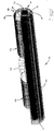
- FIG. 1 shows an exemplary aircraft 10 having an upper lobe cargo system in accordance with the present invention installed therein.
- the example shows a wide body aircraft originally configured for passenger service, specifically a Boeing B-777, however it will be understood that the system may be installed in other suitable models and types of aircraft.
- the aircraft includes a main fuselage section 12, with a nose section 14 housing control and supernumerary spaces at the forward end, an empennage section 16 at the aft end, and a wing section 18 at an intermediate location.
- the main fuselage section 12 includes an upper lobe 20 and lower lobe 22, separated by the generally horizontal main deck 24.
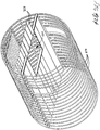
- the main fuselage section is typically more-or-less cylindrical in shape over most of its length, the lower lobe being interrupted by a wing box 26 to form forward and aft cargo holds 30, 32; conventionally, the main shell of the fuselage section is formed by a series of more-or-less circular, rib-like frames or formers over which the skin is mounted, the skin not being shown in FIG. 2 .
- the upper lobe typically extends substantially the full length of the main fuselage section, and forms the main passenger compartment in aircraft that are configured for passenger service.
- access to the upper lobe is typically via one or more comparatively small passenger doors 34, while the fore and aft cargo areas are provided with large cargo hatches 36a, 36b that are able to accommodate containers far larger than could pass through the passenger door or doors 34.
- the lower lobe may also include a smaller bulk cargo door 38, in the area of the lower lobe rearward of the aft containerized cargo compartment.
- standardized cargo containers 39 can be loaded into the lower holds 30, 32 through hatches 36a, 36b in one or more rows, as indicated at 40 in FIG. 1 .
- a lift conversion such as that noted above, allows the containers to then be moved from the lower deck or decks of the cargo areas to the main deck 24 of the former passenger area in one or more rows, as indicated at 42 in FIG. 1 .
- the present invention provides a system that enables this space to be largely filled with additional containerized cargo, thus greatly enhancing efficiency.
- the system of the present invention provides a suspended rack 50 that is installed to form a third level in the main fuselage section, on which additional cargo containers can be placed in one or more rows so as to fill the top portion of the upper lobe, as indicated at 44 in FIG. 1 .
- the rack 50 is suitably constructed of a series of transverse beams 54 and longitudinal rails or tracks 56 underlain by a lightweight horizontal panel 52.
- the rack 50 is supported by a trusswork 60, that is preferably constructed of a series of lightweight rods, preferably arranged so as to carry axial loads only.
- Upwardly and outwardly angled suspension rods 62 are mounted to brackets 63 at the outer sides or edges of rack 50, with the outer (distal) ends of the rods in turn being mounted to pre-existing attachment fittings 64 formed on frames 28 for supporting overhead stowage bins when the aircraft is in a passenger configuration, the stowage bins having been removed prior to installation of the overhead cargo system of the present invention.
- the angular relationship of the suspension rods and other geometry of the trusswork 60 is selected to maintain substantially the same load vectors on the frames 28, through attachment point 64, as that for which the frames were originally rated with the overhead stowage bins installed. As can be seen in FIGS.
- the trusswork 60 supporting the overhead rack 50 mounts to attachment points 64 that formerly supported the side and centerline overhead storage bins 65a, 65b, the storage bins having been removed for the conversion along with the passenger seating 66.
- the trusswork frame 60 enables the raised rack 50 to be installed and used with the pre-existing frames and attachment fittings, greatly enhancing the overall economy of the installation.
- the trusswork 60 further includes side rods 68 that extend upwardly from attachment brackets 66 at inward and upward angles to the suspension rods 62.
- the upper ends of the side rods terminate closely adjacent the inside surface of the fuselage section, proximate the inner edges of the fuselage frames 28, where they may be mounted to additional pre-existing bin attachment fittings, and where they are connected to a horizontal upper rod 70 that extends parallel to rack 50 and that spans the top of the trusswork frame 60.
- the side and upper rods 68 and 70 thus cooperate with rack 50 to form a framework having a generally quadrilateral cross-section and an open interior passage 72.
- the horizontal lower panel 52 acts as a shear panel to transfer fore-aft loads to the sides of the suspended rack, where fore/aft aligned diagonal rods react the loads to the fuselage shell, and also serves as a drip shield to channel liquid into drains that run to the belly of the aircraft.
- the interior passage 72 defined by the quadrilateral framework is dimensioned to be able to receive a standardized cargo container 74 of predetermined size.
- the height between the rack 50 and top bar 70 is designed to be just slightly higher than the predetermined height of the containers 74, while the lateral spacing between the upper ends of the side rods 68 as defined by top rod 70, is selected to be just slightly greater than the predetermined width of the containers, with sufficient clearance to allow the containers to move longitudinally through the spaces 72.
- the framework and deck hold the containers essentially as high in the upper lobe of the fuselage as is possible given the width of the containers; the lower side of the rack 50, in turn, is positioned a height "h" (see FIG. 6 ) above the main deck 24 that is sufficient to accommodate one or more rows of standardized containers 80, sized for example to fit within the height of the underlying cargo compartments.
- the containers are restrained by stops and/or other fittings attached to the longitudinal and/or lateral members 54, 56 of the suspended rack.
- a further advantage of the generally quadrilateral cross-section of the trusswork frame 60 is to allow the system to be installed while leaving clearance for preexisting or re-routed ventilation ducts 76a, 76b and other lines that are typically installed in the upper sides of the fuselage section. Still further, the angle of the suspension rods 62, upwardly and outwardly from the edges of rack 50, provides overhead clearance at the outboard sides of the suspended rack 50, as indicated at 82 in FIG. 6 , thus allowing personnel 84 to walk the full length of main deck 24 without having to stoop or hunch over.
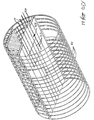
- FIGS. 8-9 illustrate an upper lobe suspended rack assembly 150 in accordance with another embodiment of the present invention.
- the storage area formed by the rack is somewhat similar in cross-section to that of the embodiment illustrated in FIGS. 4-7 and similarly positions the containers close to the crown of the fuselage, however, the structure and the manner in which loads are distributed into the fuselage are somewhat different in the embodiment shown in FIGS. 8-9 .
- the rack assembly 50 is constructed of a series of somewhat U-shaped frames 152, preferably mounted at each fuselage frame 28 over the length of the fuselage in which the rack assembly is installed.
- Each rack frame 152 includes a crossbeam 154 that extends horizontally across the fuselage when the frame is installed, with a suspension beam 156 extending at an upward and outward angle (e.g., approximately 70° to horizontal) at each end.
- Spreader or crossbeams 158 are in turn mounted to the upper, outboard ends of the upwardly extending suspension beams, in a somewhat T-shaped configuration.
- the angle in which the spreader beams 158 are mounted to the suspension beams is selected such that the two ends of the spreader beams extend upwardly-inwardly and downwardly-outwardly from the suspension beams to locations that are positioned generally proximate each fuselage frame 28; in the preferred embodiment that is illustrated, the upper ends of the spreader beams extend at an upward and inward angle of about 120° to the suspension beams, while the lower ends extend at a downward and outward angle of about 60°. It will be understood that angles may vary somewhat depending on rack size, fuselage configuration, attachment point locations and other design factors, and that the foregoing angles are therefore given by way of example rather than limitation.
- each spreader beam 158 are connected to the same frame 28 on opposite sides of the fuselage, preferably utilizing pre-existing overhead bin attachment points as discussed above.
- the outboard/lower ends of the spreader beams are supported from the frame 28 by relatively short rod members 160 having yokes 162 at their upper ends that are pivotably pinned to the fuselage frame, and brackets 164 at their lower ends that are pivotably connected to the ends of the spreader beams.
- the spreader beams and connection points are preferably dimensioned and located so that the lower/outer rods 160 are aligned generally vertically as shown in FIG. 8 and therefore loaded primarily in tension to support the weight of the rack and the cargo carried thereon.
- the upper/inboard ends of the spreader beams are similarly connected to attachment points on the fuselage frame 28 by means of comparatively short rod members 166 pivotably mounted to the frame and the beam ends by yokes 162 and brackets 164, but preferably at a more inwardly directed angle (e.g., approximately 45°) to both support the rack/cargo and stabilize it against lateral movement.
- the angles of the rods and their locations also serve to mimic the types and directions of loads exerted by the overhead bins for which the attachment points were originally selected and engineered, facilitating both engineering and load calculations for the rack assembly and also potentially simplifying certification issues.
- the beam members 154, 156, 158 which are suitably formed of aluminum alloy, fiber composite or other material having suitable strength and weight characteristics, and that are joined by fasteners, welding, adhesives, co-molding or other means suitable to the material, thus form rigid frame elements 152 that are suspended from the fuselage frames from the rod members 160, 166.
- a series of the frame members 152 are mounted in a substantially identical manner to the fuselage frames 28 over a length of the fuselage in which the upper lobe cargo rack is installed.
- the rack frames 152 are mounted at each fuselage frame 28 over the length of the installation, enhancing the strength and load carrying capacity of the rack system; in those instances where the fuselage being converted does not include pre-existing mounting points for overhead bins at each frame 28 (e.g., where the mounting points are provided at every other frame), corresponding attachment points can be formed on the intermediate frames using a jig or other suitable mechanism.
- a panel or series of panels 168 is mounted to the lower, horizontal beam members 154 of the frames over the length of the rack to form an integrated assembly, both for purposes of rigidity and strength and to prevent excessive fore-aft movement of the assembly.
- Longitudinal roller tracks 170 are in turn installed over the tops of the horizontal beams 154 to support movement of containers thereover in a manner also similar to the embodiment described above.
- the rack assembly thus forms an upper lobe cargo area 172 that supports the load of cargo containers 174 at a level above the containers 176 on the main deck 24 of the aircraft.
- the rack system 150 greatly improves utilization of volume available within the fuselage.
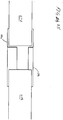
- the loadings made possible by the rack assembly may in some instances have the potential to create deformation or "bowing" of the upper fuselage under some circumstances.
- application of the inward/downward loads of the loaded rack assembly to the upper sides of the fuselage may potentially cause the frames 28 and surrounding shell of the fuselage to bend inwardly somewhat at the sides and bulge upwardly somewhat at the crown.
- the rack installation 150 further includes a series of rigid, fixed length spanner bars 180 that are mounted horizontally across the fuselage frames 28 using links 182, above the upper load cargo space 172 formed by the rack assembly, and preferably in accompaniment with each rack frame 152. Cables 184 in turn extend at outward and downward angles from the approximate midpoints 186 of the suspension beams 156 of the rack frames 152, to links 188 mounted lower down on the sides of the fuselage but still high enough to provide clearance for the containers 176 on the main deck 24.
- the spanner bar resists inner loads on the fuselage frame 28 in compression while the cables 184 resist outward loads in tension, thus maintaining the generally circular form of the frames 28 and thereby avoiding inward/outward bowing of the upper fuselage due to the loads carried on the upper lobe rack.
- each of the lift mechanisms 90, 92 in the example illustrated therein includes a lift fork assembly 94 made up of a series of projecting, longitudinally extending tines 96 supported on a triangular frame constructed of a horizontal bar 98, a vertical center post 100, and angled bars 102a, 102b that connect the ends of the main horizontal bar 98 to the top of the center post 100.
- the forks 94 are sized to fit under the containers 74 over substantially all or most of the length thereof, while the framework 94 provides rigidity and support to the tines while raising/lowering the containers.
- an upwardly gusseted bracket 104 is mounted at the base end of each of the fork tines 96.
- Paired rollers 108 (shown in phantom in FIG. 13 ) are mounted on the ends of brackets 104 opposite the tines and are captured for vertical rolling movement in stanchions 110, each of the stanchions being formed by a pair of parallel, inwardly facing C-section channel members 112 that are sized to receive rollers 108 in rolling engagement therewith.
- the adjoining channel members of each stanchion are spaced apart slightly to form a slot 114 sized to accommodate the cooperating bracket 104, so as to permit the latter to move freely along the stanchion while retaining the paired rollers therein.
- the stanchions 110 thus provide support for the fork assembly 94 of each lift mechanism, while allowing the fork assembly to move in upward and downward directions.
- the center post 100 of the fork assembly is mounted to the upper segment 118 of a telescopic hydraulic cylinder 120, the lower end of which is mounted to the main deck 24 of the fuselage.
- Hydraulic power is supplied to the telescopic cylinder by a motor (not shown) and fluid reservoir 122, to selectively move the fork assembly between a lowered position in which the tines 96 are substantially level with tracks 124 in main deck 24 (where they nest between existing roller trays) and a raised position in which the tines are substantially level with corresponding tracks 56 in the suspended rack 50, the tines including roller and the ends of the tines preferably being beveled somewhat to ease in transitioning containers between the rails and the tines.
- the forward lift mechanism 90 and in particular the stanchions 110 thereof, are preferably mounted to the aft side of a bulkhead structure 130 that is mounted at the forward end of fuselage section 12, proximate the juncture between it and the nose section 14:
- the bulkhead 130 which may be of a type referred to as "9G Bulkhead,” is manditorily installed in aircraft configured for cargo transport operations, and is intended to protect the control and supernumerary spaces 132, 134 in the nose section from cargo shifting forward in the event of a hard landing or other accident.
- Bulkhead 130 is therefore usually a relatively sturdy structure, and utilizing it as an attachment/support for the forward lift mechanism enhances both structural and space efficiency.
- the bulkhead 130 may include doorways 136a, 136b that communicate with the cargo compartment in the main fuselage section, through which personnel may enter to walk on either side of the cargo in the manner shown in FIG. 6 .
- the first containers 74 are loaded into the forward and/or rearward cargo holds 30, 32, through hatches 36a, 36b, and moved along rails 86 over the lower deck 88 into position beneath one or more lift openings 140 in the main deck 24, as shown in FIG. 5 .
- the lift mechanism at opening 90 may suitably be of the kind which is disclosed in the above-identified copending application, although it will be understood that other forms of lift mechanisms may be used.
- the lift deck selectively moves between the level of the lower cargo deck 88 and main deck 24, and is stowed in the raised position with the deck 142 (see FIG. 3 ) being latched to cooperating structures 144 at the edges of the opening.
- the lower deck lift mechanism raises the containers from the cargo compartment or compartments 30, 32 to the main deck 24, over which the containers are then moved along cooperating rails 124 until positioned over the tines 96 of the fork assembly of the forward and/or aft lift assembly 90, 92.
- the containers are then raised until level with the suspended rack assembly, and then transitioned off of the fork tines and onto the rails 56 of the suspended deck, over which they are moved longitudinally so as to fill the suspended deck to the extent desired with the upper row 44 of containers.
- additional containers are fed into the cargo holds and lifted to the main deck through openings 140 by the lower lift mechanism, so as to fill to the desired extent the main deck with the middle row 42 of containers.
- Additional containers 146 are then loaded into one or both of the lower cargo compartments and moved along rails 86 into position to fill the compartments to the extent desired with the lowermost rows 40 of containers, so that ultimately substantially all of the available volume in the fuselage section is filled with containers. Unloading can be performed in a substantially reverse sequence.
- FIGS. 14-19 illustrate a lift apparatus 190 in accordance with another example not forming part of the present invention, that serves to raise/lower cargo to/from the upper lobe storage area similar to the example shown in FIGS. 11-12 , and which among other aspects features further incorporation of the mechanism into the adjoining bulkhead, e.g., the 9G Bulkhead separating the cargo and controls/supernumerary spaces.
- a 9G Bulkhead (or equivalent) is required in cargo conversions in general, consequently incorporating the lift apparatus into the bulkhead so that the bulkhead serves both as a barrier and as a combined enclosure and support for the lift mechanism represents a significant savings in terms of weight and space.
- the term “9G Barrier” as used in this description and the appended claims includes all such barriers installed between cargo and personnel spaces, whether rated for "9G" loads or a higher or lower specifications.
- the barrier 192 of the illustrated example is constructed in four sections, namely, a pair of upward sections 194a, 194b, suitably including cutout areas 196 for doors/personnel passages, and inboard sections 198a, 198b that meet generally at the centerline of the fuselage.
- a pair of upward sections 194a, 194b suitably including cutout areas 196 for doors/personnel passages
- inboard sections 198a, 198b that meet generally at the centerline of the fuselage.
- the lift apparatus 190 includes a series of upright supports/guides that are mounted at the vertical junctions between the sections of barrier 192.
- the vertical guides/supports are formed by a series of linear guide rods, a first set 202a-b being mounted at the vertical junctions between the outward panels 194a-b and inboard panels 198a-b, and a second set 204a-b being mounted as a pair at the centerline junction between the inboard barrier sections 198a-b.
- the linear guide rods 202a-b and 204a-b are "off-the-shelf" items available from numerous suppliers, and are supported over their lengths by the structure of barrier 192, which will be described in greater detail below.
- the platform 200 of the assembly includes guide collars 206 mounted in upper and lower pairs, that engage each of the linear guide rods for vertical movement thereon.
- a ball nut assembly 210 vertically mounted at the junction between the inboard barrier sections 298a-b, at a centerline position intermediate the inboard pair of linear guides 204a-b, drives the lift platform 206 upwardly/downwardly by means of a traveling nut unit 212 on a threaded shaft 214 rotated by an electric servo motor 216 and supported in an end bearing 218, the whole being mounted on a frame plate 220, that is in turn mounted to the adjoining bulkhead sections 198a-b.
- Suitable ball screw assemblies are again available from several suppliers known to those skilled in the relevant art.
- the collars 206 that receive the linear guides are mounted in vertical pairs to upper and lower horizontal, transverse frame members 222, 224 of the lift platform 200.
- the upper and lower horizontal members are joined by vertical frame members 226, so as to react loads inwardly and outwardly directed loads onto the linear guides and from there into the structure of the barrier.
- Horizontal frame members 228 extend from the lower ends of the vertical frame members 226 to form the edges of the deck of the lift platform, the joint between the vertical and horizontal frame members being strengthened by gusset plates 230.
- Angled brace rods 232 in turn extend between the upper ends of the vertical frame members 226 and the distal ends of the horizontal frame members 228, the joint between the angled braces and the former again being strengthened by gusset plates 234.
- the distal ends of the two side frame members 228 are joined by a second transverse horizontal frame member 236 that extends generally parallel to the first horizontal frame member 224 and forms the edge of the deck of the lift platform 206.
- the deck itself is defined by a series of comparatively wide roller deck segments 238 that, as will be described in greater detail below, nest between the fixed tracks of the main deck of the aircraft for transfer of cargo onto and off of the deck of the lift platform.
- the angled stay members 232 thus cooperate with the horizontal frame members 228, 236 and 224 to support the elements of the deck under the loads of the containers/cargo carried thereon.
- the platform assembly is preferably further strengthened by a shear panel (not shown for ease of illustration) mounted over the vertical and horizontal members 226, 222, 224 at the back of the lift platform.
- roller deck segments 238 of the deck of the lift platform nest between and are level with the fixed cargo tracks 240 on the main deck of the aircraft when the platform is in the lowered position.
- Additional horizontal deck segments 242 including cargo rollers are mounted intermediate the rail segments 238 so as to nest on the main deck24 in the areas 244 between tracks 240.
- the transverse, horizontal frame bar 246 at the front of the platform is received in a series of cooperating cutouts 248 formed in the upper edges of the main deck cargo rails 240.
- the cutouts 248 also accommodate a gate member 250 that is mounted along the distal edge of the front frame member 246 on hinges 252 so that the gate lies substantially flat therein when lowered, as shown in FIG. 18 .
- the gate member 16 cooperates with the ends of the deck roller segments to arrest the gate in the vertical orientation, with the gate then being held in place by a pin, catch or other latching suitable mechanism. Also, in combination with the horizontal frame member 246, the gate member when raised forms the vertical flange of an L-shaped (in cross-section) piece across the front of the lift platform, that imparts additional rigidity and strength against forces tending to bend/twist the lift deck, e.g., due to off-center loads.
- lift assembly 190 provides a rigid, well stabilized structure for raising and lowering cargo, such as a container 174, to and from an upper lobe storage area in an efficient and safe manner, as indicated by arrow 256.
- cargo containers/pallets on the main deck can be loaded fully up to the rearward side of the bulkhead, consequently there is no loss of interior volume/capacity owing to the lift mechanism.
- the final container/pallet raised to the upper level can remain safely in place on the deck of the lift platform during flight, thus maximizing usage of the upper lobe volume as well.
- the lift mechanism of the example shown in FIGS. 14-19 may be employed in conjunction with upper lobe storage racks as disclosed herein, or may be used with other types of storage structures as well.
- FIGS. 19 and 17 also show in greater detail the internal structure of the bulkhead 192 of the illustrated example.
- each of the bulkhead sections 194a-b and 198a-b is formed of forward and aft panels 260, 262 mounted to the flanges of vertical beams 264 so as to form a rigid, lightweight structure, the upper edges of the panels being curved to follow the interior contour of the fuselage and the lower edges of being generally straight to conform to the main deck.
- the beams carry shear loads vertically into the structure of the aircraft, allowing the panels and core of the barrier to be constructed using lighter weight material.
- the spaces between the panels 260, 262 and intermediate the beams 264 are preferably filled with a lightweight material (e.g., lightweight aluminum honeycomb) which for ease of illustration is not shown.
- Additional vertical beams 264 are mounted at the junctions between the outboard and inboard panels 194a-198a and 194b-198b, with the vertical guides 202a-b being mounted to the aft edges thereof.
- the primary loads of the lift mechanism are therefore transmitted to beams 266, and from there to the fuselage/deck, as well as somewhat through the beams and panels of the adjoining bulkhead segments.
- the secondary vertical guides 204a-b of the ball screw assembly are located proximate the edges of a gap 266 formed between the panels 262 of the inboard barrier segments 198a-b, where the latter meet proximate the centerline of the aircraft with vertical beams flanking the ball screw assembly, accommodating vertical movement of the connection between the traveling nut of the ball screw assembly and the platform 200 of the lift apparatus.
- the bulkhead structure described above provides significant advantages in terms of low weight and effective transmission of loads from the lift mechanism into the body of the aircraft, however, it will be understood that the lift mechanism may also be used with forms of bulkhead construction in addition to that which is shown, e.g., with bulkheads having other types of cores.
- the platform 142 of the lower deck lift mechanism stows in a raised position, level with the main deck 24 of the fuselage (see FIG. 3 ).
- the opening 140 remains exposed, presenting a hole through the deck that is a hazard to personnel moving fore-aft through the fuselage.
- the present example provides a retractable cover assembly that extends into the opening 140 in order to permit personnel to safely transit between the adjoining forward and aft sections of the main deck.
- the cover assembly 270 is made up of a plurality of substantially parallel, longitudinally extending plate members 272, 274.
- Each of the plate members 272, 274 in the illustrated example has a length approximately equal to or greater than one-half the fore-aft dimension of the opening 270, so that when longitudinally extended the combined span fully covers the opening as shown in FIG. 21 .
- Each of the panel members comprises an elongate, generally rectangular panel, suitably constructed of a corrugated alloy or composite sheet sandwiched between horizontal upper and lower panels to give adequate strength/rigidity to support the weight of one or more personnel.
- the edges of the plate members 270, 272 are supported in rolling engagement with cooperating portions of preexisting longitudinally extending seat tracks 276.
- the extending seat tracks are installed in the main deck of the fuselage section as part of the original passenger configuration, and as can be seen in FIG. 24 they include upwardly facing channel portions 278 that receive cooperating flange portions (not shown) on the seats, that allow the latter to be mounted at the desired pitch.
- the depending portions of the seat tracks 276 further include outwardly facing lower channel portions 280a, 280b, defined by horizontal upper flange portions 282 in conjunction with horizontal lower flange portions 284 having raised outer lips.
- edges of the plate members 272, 274 are in turn supported from the underfloor portions of the seat tracks 276, by guides that allow the plate member to be selectively extended/retracted in a linear direction.
- the edges of the plate members may be supported by ball-bearing linear guides, similar in operation to drawer slides, mounted to the depending sides of the seat tracks.
- the plate members may be supported by rollers along the longitudinal edges of the plate members that are received in the lower, generally C-shaped channels 280a, 280b of the seat tracks, the wheels of the rollers being spaced outwardly from the longitudinal edges of the plate members on horizontal axles to form gaps that accommodate the upturned lips of the lower flanges and the rollers having a diameter sized just slightly less than the height between the horizontal flanges 282, 284 so as to form a rolling engagement with the channels.
- the plate members 272, 274 of the cover are thus supported parallel to and immediately below the floor panels 286, above the transverse beams 290 of the main deck 24 and over the underlying cargo compartments.
- the first set of the plate members 272 is installed between adjoining seat tracks at the forward edge of the main deck opening 140, while the corresponding set of plate members 274 is installed between the seat tracks at the rearward edge 186.
- the plate members 272, 274 are selectively extensible into and retractable from the opening 140, in the directions indicated by double-ended arrow 292 in FIG. 22 .
- the panel members When extended, the panel members are supported in a cantilever manner by the roller guides at their base ends from the seat rail channels 276.
- the distal ends of opposing pairs of the plate members 272, 274 include horizontally aligned channel pieces 294 and cooperating tongue pieces 296, that interfit in a tongue-and-groove manner when the plate members meet proximate the middle of the opening to provide additional rigidity and help to hold the extended panel members flat under the weight of a person thereover.
- the channel and tongue pieces may be mounted to the plate members 272, 274 individually, or they may be elongate pieces mounted across the ends of their respective sets of plate members so as to join the sets of plate members together for movement as a single unit.
- both sets of panel members are extended to meet at the middle of the opening, as shown in FIG. 21 , they form a continuous, substantially rigid cover over which personnel can safely pass. Then, when desired, the panel members can be retracted into their respective edges of opening 140, to permit the lift to raise/lower containers therethrough and to also be stowed therein, as described above. Extension and retraction can be performed manually, or for example by a suitable hydraulically- or electrically-operated mechanism, such as a power drive unit (PDU) for example.
- PDU power drive unit
Claims (9)
- Un appareil pour transporter une cargaison dans un aéronef (10) configuré à l'origine pour un service passagers, ledit appareil comprenant :un ensemble crémaillère (50) pouvant être monté dans une partie supérieure d'un fuselage (12) dudit aéronef (10) de manière à définir une zone de cargaison (172) dans un lobe supérieur (20) de celui-ci, ledit ensemble crémaillère (50) comprenant :
une pluralité de cadres de crémaillère transversaux (152) pouvant être montés à intervalles sur des cadres (28) dudit fuselage dudit aéronef (10) ; et des moyens pour supporter une pluralité de conteneurs de cargaison (74) disposés longitudinalement sur ledit ensemble crémaillère (50) à l'intérieur de ladite zone de cargaison (172) dans ledit lobe supérieur (20) dudit aéronef, lesdits cadres de crémaillère transversaux (152) comprenant chacun :un élément de cadre inférieur (54) qui s'étend sensiblement de manière horizontale pour former un côté inférieur de ladite zone de cargaison (172) ; etdes premier et deuxième éléments de cadre de suspension (62) qui s'étendent généralement vers le haut à partir dudit élément de cadre inférieur vers des emplacements sur ledit cadre dudit fuselage à partir duquel ledit ensemble crémaillère (50) est configuré pour être suspendu,caractérisé en ce que ledit ensemble crémaillère (50) comprend en outre :
des moyens configurés pour supporter lesdits éléments de cadre de suspension s'étendant vers le haut (62) desdits cadres de crémaillère transversaux (152) à partir de points de fixation de compartiment à bagages préexistants (64) sur lesdits cadres (28) dudit fuselage, l'ensemble crémaillère (50) étant configuré pour être installé avec les points de fixation de compartiment à bagages préexistants (64). - L'appareil selon la revendication 1, dans lequel lesdits moyens pour supporter ladite pluralité de conteneurs de cargaison (74) sur ledit ensemble crémaillère (50) comprend :
au moins un rail de cargaison (56) s'étendant généralement de manière longitudinale à travers une pluralité desdits éléments de cadre inférieur (54) d'une pluralité desdits cadres de crémaillère (152). - L'appareil selon la revendication 1, dans lequel lesdits moyens pour supporter lesdits éléments de cadre de suspension s'étendant vers le haut (62) desdits cadres de crémaillère transversaux (152) à partir desdits points de fixation de compartiment à bagages préexistants (64) comprennent :
au moins un élément de liaison pivotant pour interconnecter une extrémité supérieure de chacun desdits éléments de cadre de suspension (62) à l'un desdits points de fixation de compartiment à bagages préexistants (64) sur ledit cadre (28) dudit fuselage (12). - L'appareil selon la revendication 3, dans lequel ledit au moins un élément de liaison pivotant comprend :
un élément de liaison pivotant aligné pour transmettre des charges à partir dudit cadre de crémaillère transversal (152) dudit ensemble crémaillère (50) vers ledit cadre (28) dudit fuselage (12) dans une direction généralement radiale. - L'appareil selon la revendication 4, dans lequel les cadres de crémaillère transversaux (152) dudit ensemble crémaillère (50) comprennent en outre :des éléments de traverse montés sur lesdites extrémités supérieures desdits éléments de cadre de suspension (62) et ayant des extrémités supérieure et inférieure ;lesdites extrémités supérieure et inférieure desdits éléments de traverse pouvant être fixées par lesdits éléments de liaison pivotants auxdits points de fixation de compartiment à bagages préexistants.
- L'appareil selon la revendication 3, comprenant en outre :au moins une barre rigide (180) pouvant être montée transversalement à travers une extrémité supérieure du cadre dudit fuselage (12) au-dessus de ladite zone de cargaison (172) dudit ensemble crémaillère (50) pour maintenir ledit cadre contre une inclinaison vers l'intérieur sous des charges exercées par ledit ensemble crémaillère (50) ; etau moins un câble de tension pour interconnecter chacun desdits éléments de poutre de suspension s'étendant vers le haut audit cadre dudit fuselage (12) pour empêcher ledit cadre (28) de s'incliner vers l'extérieur sous des charges exercées par ledit ensemble crémaillère (50).
- L'appareil selon la revendication 3, dans lequel ledit ensemble crémaillère (50) est configuré pour étendre sensiblement une longueur complète d'une section de fuselage principale dudit aéronef (10).
- L'appareil selon la revendication 6, dans lequel la barre rigide (180) comprend une barre de serrage rigide.
- L'appareil selon la revendication 1, dans lequel l'ensemble crémaillère (50) comprend en outre au moins un élément de panneau sensiblement horizontal (52) monté sur lesdits éléments de cadre inférieur (54) de ladite pluralité de cadres de crémaillère transversaux (152) de manière à former un panneau de cisaillement pour ledit ensemble crémaillère (50).
Applications Claiming Priority (3)
| Application Number | Priority Date | Filing Date | Title |
|---|---|---|---|
| US45536910P | 2010-10-18 | 2010-10-18 | |
| US45875610P | 2010-11-30 | 2010-11-30 | |
| PCT/US2011/001778 WO2012054080A2 (fr) | 2010-10-18 | 2011-10-18 | Système pour le stockage par le dessus de conteneurs de fret dans un lobe supérieur d'aéronef |
Publications (2)
| Publication Number | Publication Date |
|---|---|
| EP2630037A2 EP2630037A2 (fr) | 2013-08-28 |
| EP2630037B1 true EP2630037B1 (fr) | 2020-01-22 |
Family
ID=44906354
Family Applications (1)
| Application Number | Title | Priority Date | Filing Date |
|---|---|---|---|
| EP11779001.4A Active EP2630037B1 (fr) | 2010-10-18 | 2011-10-18 | Système pour le stockage par le dessus de conteneurs de fret dans un lobe supérieur d'aéronef |
Country Status (7)
| Country | Link |
|---|---|
| US (1) | US8702036B2 (fr) |
| EP (1) | EP2630037B1 (fr) |
| CN (1) | CN103221306B (fr) |
| BR (1) | BR112013009451A2 (fr) |
| IL (1) | IL225477A (fr) |
| SG (2) | SG10201705688QA (fr) |
| WO (1) | WO2012054080A2 (fr) |
Families Citing this family (13)
| Publication number | Priority date | Publication date | Assignee | Title |
|---|---|---|---|---|
| CN103221306B (zh) * | 2010-10-18 | 2016-11-23 | 詹姆斯·M·柯里 | 用于飞机的上圆形突出部中的货物集装箱的高架存储的系统 |
| EP2655194B1 (fr) * | 2010-12-23 | 2017-05-17 | Airbus Operations GmbH | Système de support de composants de système d'aéronef et procédé de montage |
| US8864079B2 (en) * | 2012-10-08 | 2014-10-21 | The Boeing Company | Aircraft cargo compartment container crane system |
| FR3000031B1 (fr) * | 2012-12-21 | 2015-11-13 | Airbus Operations Sas | Module de soute avionique a plancher superieur integre |
| US9656735B2 (en) * | 2014-03-06 | 2017-05-23 | Bell Helicopter Textron Inc. | Skin impact snubber |
| US9694909B2 (en) * | 2014-07-17 | 2017-07-04 | Aai Corporation | Modular mounting structure with embedded electrical bus |
| CN106986030B (zh) * | 2017-04-21 | 2019-05-21 | 陕西飞机工业(集团)有限公司 | 一种机舱滚道装置 |
| US10577106B2 (en) * | 2017-08-31 | 2020-03-03 | The Boeing Company | System and method for restraining cargo |
| US10589969B2 (en) * | 2018-04-25 | 2020-03-17 | Rinaldo Brutoco | System, method and apparatus for widespread commercialization of hydrogen as a carbon-free alternative fuel source |
| US10793247B2 (en) * | 2018-05-01 | 2020-10-06 | The Boeing Company | Enclosure for storing electronic components in overhead space of an aircraft |
| US11136137B2 (en) * | 2018-09-10 | 2021-10-05 | Rockwell Collins, Inc. | Non-intrusive passenger rest cabin monitoring system |
| US11661193B2 (en) * | 2019-07-18 | 2023-05-30 | Elroy Air, Inc. | Unmanned aerial vehicle optimization |
| US11254415B2 (en) | 2019-12-12 | 2022-02-22 | The Boeing Company | Aircraft wing flap support |
Family Cites Families (18)
| Publication number | Priority date | Publication date | Assignee | Title |
|---|---|---|---|---|
| US3028130A (en) | 1957-11-01 | 1962-04-03 | Douglas Aircraft Co Inc | Cargo handling means for airplanes |
| US3019757A (en) * | 1959-05-07 | 1962-02-06 | Wells Fargo Bank Americ Compan | Vertically adjustable ship decks |
| US4287967A (en) * | 1979-06-08 | 1981-09-08 | Sanscord Australia Pty. Limited | Self-supporting and self-contained elevator |
| US4653707A (en) * | 1984-12-28 | 1987-03-31 | The Boeing Company | Personnel elevator for commercial aircraft |
| DE3501887A1 (de) * | 1985-01-22 | 1986-07-24 | Radij Petrovič Papkovskij | Kabine eines flugapparates |
| IL96799A (en) * | 1990-12-27 | 1995-11-27 | Fuselage Eng Services | Aircraft fuselage construction including food carrier |
| IL103217A (en) * | 1992-09-18 | 1995-10-31 | Fuselage Eng Services | Vehicle cabin construction |
| GB9500241D0 (en) * | 1994-03-04 | 1995-03-01 | L W A Gibraltar Limited | Aircraft cargo elevator |
| US5868544A (en) * | 1996-10-11 | 1999-02-09 | Mcdonnell Douglas Corporation | Airborne cargo loader |
| EP1873059A3 (fr) * | 2000-06-06 | 2012-04-11 | Mitsubishi Heavy Industries, Ltd. | Avion doté de cabines à plusieurs niveaux pour fret ou passagers et procédé de chargement de fret dans ledit avion |
| US8011617B2 (en) | 2005-06-17 | 2011-09-06 | Curry James M | Compact cargo lift for commerical aircraft |
| DE102005048709A1 (de) * | 2005-10-12 | 2007-04-26 | Airbus Deutschland Gmbh | Vertikal beweglicher Gang für Ruheräume im Deckenbereich |
| US8866915B2 (en) * | 2005-11-15 | 2014-10-21 | Lawrence Livermore National Security, Llc | High speed, real-time, camera bandwidth converter |
| FR2894225B1 (fr) * | 2005-12-07 | 2008-01-11 | Airbus France Sa Sa | Mur de cloisonnement pour carenage ventral d'aeronef et aeronef muni d'un carenage ventral |
| US8387918B2 (en) * | 2006-09-15 | 2013-03-05 | The Boeing Company | Multi-directional support arm |
| DE102008007838B4 (de) * | 2008-02-07 | 2013-07-18 | Airbus Operations Gmbh | Fußbodensystem für eine Rumpfzelle eines Flugzeugs |
| CN103221306B (zh) * | 2010-10-18 | 2016-11-23 | 詹姆斯·M·柯里 | 用于飞机的上圆形突出部中的货物集装箱的高架存储的系统 |
| DE102011102364A1 (de) * | 2011-05-24 | 2012-11-29 | Airbus Operations Gmbh | Freitragendes Kabinenstruktursegment |
-
2011
- 2011-10-18 CN CN201180050371.5A patent/CN103221306B/zh active Active
- 2011-10-18 WO PCT/US2011/001778 patent/WO2012054080A2/fr active Application Filing
- 2011-10-18 EP EP11779001.4A patent/EP2630037B1/fr active Active
- 2011-10-18 BR BR112013009451-6A patent/BR112013009451A2/pt not_active Application Discontinuation
- 2011-10-18 US US13/317,493 patent/US8702036B2/en active Active
- 2011-10-18 SG SG10201705688QA patent/SG10201705688QA/en unknown
- 2011-10-18 SG SG2013025655A patent/SG189288A1/en unknown
-
2013
- 2013-03-24 IL IL225477A patent/IL225477A/en active IP Right Grant
Non-Patent Citations (1)
| Title |
|---|
| None * |
Also Published As
| Publication number | Publication date |
|---|---|
| WO2012054080A9 (fr) | 2016-07-07 |
| US8702036B2 (en) | 2014-04-22 |
| BR112013009451A2 (pt) | 2020-10-27 |
| SG189288A1 (en) | 2013-05-31 |
| IL225477A0 (en) | 2013-06-27 |
| WO2012054080A2 (fr) | 2012-04-26 |
| IL225477A (en) | 2017-07-31 |
| SG10201705688QA (en) | 2017-08-30 |
| WO2012054080A3 (fr) | 2012-10-26 |
| WO2012054080A4 (fr) | 2012-12-27 |
| CN103221306B (zh) | 2016-11-23 |
| US20120160961A1 (en) | 2012-06-28 |
| EP2630037A2 (fr) | 2013-08-28 |
| CN103221306A (zh) | 2013-07-24 |
Similar Documents
| Publication | Publication Date | Title |
|---|---|---|
| EP2630037B1 (fr) | Système pour le stockage par le dessus de conteneurs de fret dans un lobe supérieur d'aéronef | |
| US6302358B1 (en) | Quick Change system and method for converting an aircraft from a cargo mode to a passenger mode and vice versa | |
| EP1211174B1 (fr) | Aeronef comportant plusieurs cabines superieures et inferieures faisant office de compartiment a marchandises ou de cabines a passagers, et procede de chargement de marchandises sur un aeronef | |
| US8011617B2 (en) | Compact cargo lift for commerical aircraft | |
| US7395989B2 (en) | Aircraft fuselage and corresponding aircraft | |
| US5752673A (en) | Passenger aircraft with increased passenger capacity | |
| US4929133A (en) | Loading pallet for aircraft cargo containers | |
| US6848654B1 (en) | Modular offset aisle overhead crew rest | |
| US9975636B2 (en) | Cargo restraining assembly, cargo loading system and aircraft | |
| US8979025B1 (en) | Compact cargo lift for commercial aircraft | |
| US10589836B2 (en) | Split level forward double deck airliner | |
| US9452817B1 (en) | Aircraft having split level cabin floors | |
| DE202020102904U1 (de) | Frachtcontainer für eine ununterbrochene Transportkette für Kabinenfracht und Passagiersitzanordnung in einer Passagierkabine | |
| EP3263457B1 (fr) | Avion à double cabine avant à niveau séparé | |
| US20220380018A1 (en) | Aircraft fuselage assembly with a cargo floor assembly | |
| EP2640635B1 (fr) | Élévateur de fret compact pour avion commercial | |
| DE102016004717B4 (de) | Schnelles Be- und Entladen von Passagierflugzeugen | |
| RU2285637C2 (ru) | Грузовая кабина транспортного самолета преимущественно ан-124-100 | |
| NL2025867B1 (en) | Cargo stowage container, method of transporting cargo in a passenger plane, and passenger plane configured therefor | |
| CN117163278B (zh) | 一种挂装式模块化整体货舱及上单翼货运飞机 | |
| GB2500767A (en) | System for loading passengers into a vehicle | |
| US20230060580A1 (en) | System and method for passenger plane to cargo plane conversion | |
| US20220315247A1 (en) | Integral floor module, cargo loading system, latch element and method for converting a passenger deck into a cargo deck | |
| WO2022013299A1 (fr) | Transport de frêt dans la cabine passagers d'avions commerciaux |
Legal Events
| Date | Code | Title | Description |
|---|---|---|---|
| PUAI | Public reference made under article 153(3) epc to a published international application that has entered the european phase |
Free format text: ORIGINAL CODE: 0009012 |
|
| 17P | Request for examination filed |
Effective date: 20130513 |
|
| AK | Designated contracting states |
Kind code of ref document: A2 Designated state(s): AL AT BE BG CH CY CZ DE DK EE ES FI FR GB GR HR HU IE IS IT LI LT LU LV MC MK MT NL NO PL PT RO RS SE SI SK SM TR |
|
| DAX | Request for extension of the european patent (deleted) | ||
| 17Q | First examination report despatched |
Effective date: 20160628 |
|
| STAA | Information on the status of an ep patent application or granted ep patent |
Free format text: STATUS: EXAMINATION IS IN PROGRESS |
|
| GRAP | Despatch of communication of intention to grant a patent |
Free format text: ORIGINAL CODE: EPIDOSNIGR1 |
|
| STAA | Information on the status of an ep patent application or granted ep patent |
Free format text: STATUS: GRANT OF PATENT IS INTENDED |
|
| INTG | Intention to grant announced |
Effective date: 20190819 |
|
| GRAS | Grant fee paid |
Free format text: ORIGINAL CODE: EPIDOSNIGR3 |
|
| GRAA | (expected) grant |
Free format text: ORIGINAL CODE: 0009210 |
|
| STAA | Information on the status of an ep patent application or granted ep patent |
Free format text: STATUS: THE PATENT HAS BEEN GRANTED |
|
| AK | Designated contracting states |
Kind code of ref document: B1 Designated state(s): AL AT BE BG CH CY CZ DE DK EE ES FI FR GB GR HR HU IE IS IT LI LT LU LV MC MK MT NL NO PL PT RO RS SE SI SK SM TR |
|
| REG | Reference to a national code |
Ref country code: GB Ref legal event code: FG4D |
|
| REG | Reference to a national code |
Ref country code: CH Ref legal event code: EP |
|
| REG | Reference to a national code |
Ref country code: AT Ref legal event code: REF Ref document number: 1226767 Country of ref document: AT Kind code of ref document: T Effective date: 20200215 |
|
| REG | Reference to a national code |
Ref country code: IE Ref legal event code: FG4D |
|
| REG | Reference to a national code |
Ref country code: DE Ref legal event code: R096 Ref document number: 602011064749 Country of ref document: DE |
|
| REG | Reference to a national code |
Ref country code: NL Ref legal event code: MP Effective date: 20200122 |
|
| REG | Reference to a national code |
Ref country code: LT Ref legal event code: MG4D |
|
| PG25 | Lapsed in a contracting state [announced via postgrant information from national office to epo] |
Ref country code: FI Free format text: LAPSE BECAUSE OF FAILURE TO SUBMIT A TRANSLATION OF THE DESCRIPTION OR TO PAY THE FEE WITHIN THE PRESCRIBED TIME-LIMIT Effective date: 20200122 Ref country code: NO Free format text: LAPSE BECAUSE OF FAILURE TO SUBMIT A TRANSLATION OF THE DESCRIPTION OR TO PAY THE FEE WITHIN THE PRESCRIBED TIME-LIMIT Effective date: 20200422 Ref country code: RS Free format text: LAPSE BECAUSE OF FAILURE TO SUBMIT A TRANSLATION OF THE DESCRIPTION OR TO PAY THE FEE WITHIN THE PRESCRIBED TIME-LIMIT Effective date: 20200122 Ref country code: NL Free format text: LAPSE BECAUSE OF FAILURE TO SUBMIT A TRANSLATION OF THE DESCRIPTION OR TO PAY THE FEE WITHIN THE PRESCRIBED TIME-LIMIT Effective date: 20200122 Ref country code: PT Free format text: LAPSE BECAUSE OF FAILURE TO SUBMIT A TRANSLATION OF THE DESCRIPTION OR TO PAY THE FEE WITHIN THE PRESCRIBED TIME-LIMIT Effective date: 20200614 |
|
| PG25 | Lapsed in a contracting state [announced via postgrant information from national office to epo] |
Ref country code: BG Free format text: LAPSE BECAUSE OF FAILURE TO SUBMIT A TRANSLATION OF THE DESCRIPTION OR TO PAY THE FEE WITHIN THE PRESCRIBED TIME-LIMIT Effective date: 20200422 Ref country code: IS Free format text: LAPSE BECAUSE OF FAILURE TO SUBMIT A TRANSLATION OF THE DESCRIPTION OR TO PAY THE FEE WITHIN THE PRESCRIBED TIME-LIMIT Effective date: 20200522 Ref country code: GR Free format text: LAPSE BECAUSE OF FAILURE TO SUBMIT A TRANSLATION OF THE DESCRIPTION OR TO PAY THE FEE WITHIN THE PRESCRIBED TIME-LIMIT Effective date: 20200423 Ref country code: HR Free format text: LAPSE BECAUSE OF FAILURE TO SUBMIT A TRANSLATION OF THE DESCRIPTION OR TO PAY THE FEE WITHIN THE PRESCRIBED TIME-LIMIT Effective date: 20200122 Ref country code: LV Free format text: LAPSE BECAUSE OF FAILURE TO SUBMIT A TRANSLATION OF THE DESCRIPTION OR TO PAY THE FEE WITHIN THE PRESCRIBED TIME-LIMIT Effective date: 20200122 Ref country code: SE Free format text: LAPSE BECAUSE OF FAILURE TO SUBMIT A TRANSLATION OF THE DESCRIPTION OR TO PAY THE FEE WITHIN THE PRESCRIBED TIME-LIMIT Effective date: 20200122 |
|
| REG | Reference to a national code |
Ref country code: DE Ref legal event code: R097 Ref document number: 602011064749 Country of ref document: DE |
|
| PG25 | Lapsed in a contracting state [announced via postgrant information from national office to epo] |
Ref country code: CZ Free format text: LAPSE BECAUSE OF FAILURE TO SUBMIT A TRANSLATION OF THE DESCRIPTION OR TO PAY THE FEE WITHIN THE PRESCRIBED TIME-LIMIT Effective date: 20200122 Ref country code: RO Free format text: LAPSE BECAUSE OF FAILURE TO SUBMIT A TRANSLATION OF THE DESCRIPTION OR TO PAY THE FEE WITHIN THE PRESCRIBED TIME-LIMIT Effective date: 20200122 Ref country code: ES Free format text: LAPSE BECAUSE OF FAILURE TO SUBMIT A TRANSLATION OF THE DESCRIPTION OR TO PAY THE FEE WITHIN THE PRESCRIBED TIME-LIMIT Effective date: 20200122 Ref country code: LT Free format text: LAPSE BECAUSE OF FAILURE TO SUBMIT A TRANSLATION OF THE DESCRIPTION OR TO PAY THE FEE WITHIN THE PRESCRIBED TIME-LIMIT Effective date: 20200122 Ref country code: SK Free format text: LAPSE BECAUSE OF FAILURE TO SUBMIT A TRANSLATION OF THE DESCRIPTION OR TO PAY THE FEE WITHIN THE PRESCRIBED TIME-LIMIT Effective date: 20200122 Ref country code: SM Free format text: LAPSE BECAUSE OF FAILURE TO SUBMIT A TRANSLATION OF THE DESCRIPTION OR TO PAY THE FEE WITHIN THE PRESCRIBED TIME-LIMIT Effective date: 20200122 Ref country code: EE Free format text: LAPSE BECAUSE OF FAILURE TO SUBMIT A TRANSLATION OF THE DESCRIPTION OR TO PAY THE FEE WITHIN THE PRESCRIBED TIME-LIMIT Effective date: 20200122 Ref country code: DK Free format text: LAPSE BECAUSE OF FAILURE TO SUBMIT A TRANSLATION OF THE DESCRIPTION OR TO PAY THE FEE WITHIN THE PRESCRIBED TIME-LIMIT Effective date: 20200122 |
|
| REG | Reference to a national code |
Ref country code: AT Ref legal event code: MK05 Ref document number: 1226767 Country of ref document: AT Kind code of ref document: T Effective date: 20200122 |
|
| PLBE | No opposition filed within time limit |
Free format text: ORIGINAL CODE: 0009261 |
|
| STAA | Information on the status of an ep patent application or granted ep patent |
Free format text: STATUS: NO OPPOSITION FILED WITHIN TIME LIMIT |
|
| 26N | No opposition filed |
Effective date: 20201023 |
|
| REG | Reference to a national code |
Ref country code: DE Ref legal event code: R082 Ref document number: 602011064749 Country of ref document: DE Representative=s name: HL KEMPNER PATENTANWAELTE, SOLICITORS (ENGLAND, DE Ref country code: DE Ref legal event code: R082 Ref document number: 602011064749 Country of ref document: DE Representative=s name: HL KEMPNER PATENTANWALT, RECHTSANWALT, SOLICIT, DE |
|
| PG25 | Lapsed in a contracting state [announced via postgrant information from national office to epo] |
Ref country code: AT Free format text: LAPSE BECAUSE OF FAILURE TO SUBMIT A TRANSLATION OF THE DESCRIPTION OR TO PAY THE FEE WITHIN THE PRESCRIBED TIME-LIMIT Effective date: 20200122 Ref country code: IT Free format text: LAPSE BECAUSE OF FAILURE TO SUBMIT A TRANSLATION OF THE DESCRIPTION OR TO PAY THE FEE WITHIN THE PRESCRIBED TIME-LIMIT Effective date: 20200122 |
|
| PG25 | Lapsed in a contracting state [announced via postgrant information from national office to epo] |
Ref country code: SI Free format text: LAPSE BECAUSE OF FAILURE TO SUBMIT A TRANSLATION OF THE DESCRIPTION OR TO PAY THE FEE WITHIN THE PRESCRIBED TIME-LIMIT Effective date: 20200122 Ref country code: PL Free format text: LAPSE BECAUSE OF FAILURE TO SUBMIT A TRANSLATION OF THE DESCRIPTION OR TO PAY THE FEE WITHIN THE PRESCRIBED TIME-LIMIT Effective date: 20200122 |
|
| REG | Reference to a national code |
Ref country code: CH Ref legal event code: PL |
|
| PG25 | Lapsed in a contracting state [announced via postgrant information from national office to epo] |
Ref country code: LU Free format text: LAPSE BECAUSE OF NON-PAYMENT OF DUE FEES Effective date: 20201018 Ref country code: MC Free format text: LAPSE BECAUSE OF FAILURE TO SUBMIT A TRANSLATION OF THE DESCRIPTION OR TO PAY THE FEE WITHIN THE PRESCRIBED TIME-LIMIT Effective date: 20200122 |
|
| REG | Reference to a national code |
Ref country code: BE Ref legal event code: MM Effective date: 20201031 |
|
| PG25 | Lapsed in a contracting state [announced via postgrant information from national office to epo] |
Ref country code: CH Free format text: LAPSE BECAUSE OF NON-PAYMENT OF DUE FEES Effective date: 20201031 Ref country code: BE Free format text: LAPSE BECAUSE OF NON-PAYMENT OF DUE FEES Effective date: 20201031 Ref country code: LI Free format text: LAPSE BECAUSE OF NON-PAYMENT OF DUE FEES Effective date: 20201031 |
|
| PG25 | Lapsed in a contracting state [announced via postgrant information from national office to epo] |
Ref country code: IE Free format text: LAPSE BECAUSE OF NON-PAYMENT OF DUE FEES Effective date: 20201018 |
|
| PG25 | Lapsed in a contracting state [announced via postgrant information from national office to epo] |
Ref country code: TR Free format text: LAPSE BECAUSE OF FAILURE TO SUBMIT A TRANSLATION OF THE DESCRIPTION OR TO PAY THE FEE WITHIN THE PRESCRIBED TIME-LIMIT Effective date: 20200122 Ref country code: MT Free format text: LAPSE BECAUSE OF FAILURE TO SUBMIT A TRANSLATION OF THE DESCRIPTION OR TO PAY THE FEE WITHIN THE PRESCRIBED TIME-LIMIT Effective date: 20200122 Ref country code: CY Free format text: LAPSE BECAUSE OF FAILURE TO SUBMIT A TRANSLATION OF THE DESCRIPTION OR TO PAY THE FEE WITHIN THE PRESCRIBED TIME-LIMIT Effective date: 20200122 |
|
| PG25 | Lapsed in a contracting state [announced via postgrant information from national office to epo] |
Ref country code: MK Free format text: LAPSE BECAUSE OF FAILURE TO SUBMIT A TRANSLATION OF THE DESCRIPTION OR TO PAY THE FEE WITHIN THE PRESCRIBED TIME-LIMIT Effective date: 20200122 Ref country code: AL Free format text: LAPSE BECAUSE OF FAILURE TO SUBMIT A TRANSLATION OF THE DESCRIPTION OR TO PAY THE FEE WITHIN THE PRESCRIBED TIME-LIMIT Effective date: 20200122 |
|
| PGFP | Annual fee paid to national office [announced via postgrant information from national office to epo] |
Ref country code: GB Payment date: 20231024 Year of fee payment: 13 |
|
| PGFP | Annual fee paid to national office [announced via postgrant information from national office to epo] |
Ref country code: FR Payment date: 20231009 Year of fee payment: 13 Ref country code: DE Payment date: 20231025 Year of fee payment: 13 |