EP2629708B1 - Variable size intragastric implant devices - Google Patents
Variable size intragastric implant devices Download PDFInfo
- Publication number
- EP2629708B1 EP2629708B1 EP11770987.3A EP11770987A EP2629708B1 EP 2629708 B1 EP2629708 B1 EP 2629708B1 EP 11770987 A EP11770987 A EP 11770987A EP 2629708 B1 EP2629708 B1 EP 2629708B1
- Authority
- EP
- European Patent Office
- Prior art keywords
- stomach
- patient
- feet
- balloon
- stimulator
- Prior art date
- Legal status (The legal status is an assumption and is not a legal conclusion. Google has not performed a legal analysis and makes no representation as to the accuracy of the status listed.)
- Not-in-force
Links
Images


Classifications
-
- A—HUMAN NECESSITIES
- A61—MEDICAL OR VETERINARY SCIENCE; HYGIENE
- A61F—FILTERS IMPLANTABLE INTO BLOOD VESSELS; PROSTHESES; DEVICES PROVIDING PATENCY TO, OR PREVENTING COLLAPSING OF, TUBULAR STRUCTURES OF THE BODY, e.g. STENTS; ORTHOPAEDIC, NURSING OR CONTRACEPTIVE DEVICES; FOMENTATION; TREATMENT OR PROTECTION OF EYES OR EARS; BANDAGES, DRESSINGS OR ABSORBENT PADS; FIRST-AID KITS
- A61F5/00—Orthopaedic methods or devices for non-surgical treatment of bones or joints; Nursing devices; Anti-rape devices
- A61F5/0003—Apparatus for the treatment of obesity; Anti-eating devices
- A61F5/0013—Implantable devices or invasive measures
- A61F5/003—Implantable devices or invasive measures inflatable
-
- A—HUMAN NECESSITIES
- A61—MEDICAL OR VETERINARY SCIENCE; HYGIENE
- A61F—FILTERS IMPLANTABLE INTO BLOOD VESSELS; PROSTHESES; DEVICES PROVIDING PATENCY TO, OR PREVENTING COLLAPSING OF, TUBULAR STRUCTURES OF THE BODY, e.g. STENTS; ORTHOPAEDIC, NURSING OR CONTRACEPTIVE DEVICES; FOMENTATION; TREATMENT OR PROTECTION OF EYES OR EARS; BANDAGES, DRESSINGS OR ABSORBENT PADS; FIRST-AID KITS
- A61F5/00—Orthopaedic methods or devices for non-surgical treatment of bones or joints; Nursing devices; Anti-rape devices
- A61F5/0003—Apparatus for the treatment of obesity; Anti-eating devices
- A61F5/0013—Implantable devices or invasive measures
- A61F5/0036—Intragastrical devices
- A61F5/004—Intragastrical devices remotely adjustable
Definitions
- the present invention generally relates to medical implants and uses thereof for treating obesity and/or obesity-related diseases and, more specifically, to transorally-delivered devices designed to occupy space within a stomach and/or stimulate the stomach wall.
- Obesity is caused by a wide range of factors including genetics, metabolic disorders, physical and psychological issues, lifestyle, and poor nutrition. Millions of obese and overweight individuals first turn to diet, fitness and medication to lose weight; however, these efforts alone are often not enough to keep weight at a level that is optimal for good health. Surgery is another increasingly viable alternative for those with a Body Mass Index (BMI) of greater than 40. In fact, the number of bariatric surgeries in the United States is projected to reach approximately 400,000 annually by 2010.
- BMI Body Mass Index
- Examples of surgical methods and devices used to treat obesity include the The LAP-BAND® (Allergan, Inc., Irvine, CA) gastric band and the LAP-BAND AP® (Allergan, Inc., Irvine, CA).
- LAP-BAND® Allergan, Inc., Irvine, CA
- LAP-BAND AP® Allergan, Inc., Irvine, CA
- surgery might not be an option for every obese individual; for certain patients, non-surgical therapies or minimal-surgery options are more effective or appropriate.
- intragastric balloons may be utilized as non-surgical or minimal-surgery means for treating obesity.
- One such inflatable intragastric balloon is described in U.S. Pat. No. 5,084,061 and is commercially available as the BioEnterics Intragastric Balloon System (sold under the BIB® System). These devices are designed to provide therapy for moderately obese individuals who need to shed pounds in preparation for surgery, or as part of a dietary or behavioral modification program.
- the BIB® System for example, comprises a silicone elastomer intragastric balloon that is inserted into the stomach and filled with fluid.
- the balloons are placed in the stomach in an empty or deflated state and thereafter filled (fully or partially) with a suitable fluid.
- the balloon occupies space in the stomach, thereby leaving less room available for food and creating a feeling of satiety for the patient.
- Clinical results with these devices show that for many obese patients, the intragastric balloons significantly help to control appetite and accomplish weight loss.
- Placement of such balloons is temporary, and such balloons are typically removed after about six months.
- One means of removing the balloon is to deflate it by puncturing the balloon, and either aspirating the contents of the balloon or allowing the fluid to pass into the patient's stomach.
- the acids present in a patient's stomach may erode the balloon to the point where it self-deflates. When this occurs, the deflated balloon may pass naturally through the patient's digestive system and be expelled through the bowel.
- McGhan, U.S. Pat. No. 6,733,512 describes a self-deflating intragastric balloon that includes a biodegradable inflation valve. After a certain residence time in the stomach, the valve starts to leak and eventually the balloon deflates and passes though the patient's digestive tract.
- US 2010/0049224 discloses an intragastric implant comprising an anchor and a therapeutic device or a diagnostic device.
- the anchor is adapted to extend between the fundus and the pyloric valve of a stomach, to be retained without attachment to the stomach wall, and to anchor the device within the stomach with a relatively stable position and orientation.
- the therapeutic or diagnostic device is adapted to extend from the esophagus or stomach to the intestines or stomach. The therapeutic or diagnostic device, when extending into the esophagus, will be slidably received through the gastroesophageal junction and, when extending into the intestines, will be slidably received in the pyloric valve.
- WO 2007/092390 discloses devices and methods for applying gastrointestinal stimulation include implanting a stimulation device including a body with at least one expandable portion and a bridging portion and at least one stimulation member in the gastrointestinal tract.
- the at least one stimulation member includes one or more energy delivery members, one or more sensors, or a combination of both.
- the body maintains the device within the gastrointestinal space, and preferentially within the pyloric portion of the patient's stomach, and prevents passage of the device from the gastrointestinal space, but is not rigidly anchored or affixed to the gastrointestinal wall tissue.
- WO 2011/049651 discloses a bariatric device for use in inducing weight loss, comprising a cardiac element, a pyloric element, and a connecting element between the two other elements, wherein the connecting element provides structure between the cardiac and pyloric elements, keeping them largely in place and at least intermittently touching and applying pressure to the stomach's cardiac, adjacent fundic and pyloric regions, respectively, which produces a satiety signal to the user, giving the recipient a feeling of fullness and reducing his or her hunger feelings.
- the pyloric and connecting elements may be replaced with a positioning element, which keeps the cardiac element in its relative position by pushing against various structures in the stomach.
- the bariatric device may be made from multiple sizes or adjustable, either manually, automatically or remotely, to optimally size and/or position the device to produce the desired satiety signals and weight loss. This document is prior art under Article 54(3) EPC.
- Transoral obesity treatment devices generally promote a feeling of satiety in the patient by contacting the insides of the stomach wall, reducing the space in the stomach, or otherwise reducing the amount of food consumed or digested by the patient.
- the devices have the capacity to vary in size and are desirably self-actuating in that they change shape and/or volume using internal motors or actuators. The changing character of the devices helps prevent the person's stomach from compensating for the implant, such as sometimes happens with static intragastric devices.
- transoral obesity treatment devices generally allow for easy and quick placement and removal. Surgery is usually not required or very minimal.
- the transoral obesity treatment devices are placed in the patient through the mouth, passing the esophagus and reaching the destination, usually in the stomach region. In most instances, the transoral obesity treatment device does not require suturing or stapling to the esophageal or stomach wall, and remains inside the patient's body for a lengthy period of time (e.g., months or years) before removal.
- the transoral obesity treatment device may be a stomach stimulator, which may fight obesity by stimulating the stomach walls of the patient and occupying space inside the stomach.
- the stomach stimulator may be an electromechanical device comprising a telescoping body and expandable ends. The ends may be configured to exert a pressure on the inner stomach walls of the patient and, when in the expanded state, prevent the stomach stimulator from entering the patient's intestines.
- the telescoping body shortens or lengthens the stomach stimulator, either randomly or in accordance with a predefined schedule, such that the patient's body cannot compensate. Studies have shown that obesity may be more effectively reduced when a patient's body cannot compensate to the obesity device.
- a system for treating obesity by applying a pressure to the patient's stomach comprises a central elongated body having an adjustable length.
- Two collapsible atraumatic feet on opposite ends of the elongated body are each configured to exert pressure on the patient's stomach when in a deployed position.
- An actuator within the central elongated body adjusts the length of the body and simultaneously the distance between the atraumatic feet.
- the two collapsible atraumatic feet comprise an array of living hinges that may be unfolded to an elongated delivery configuration and folded outward to a deployed configuration.
- the array of living hinges may be in an X-shape.
- the actuator may comprise an electronic motor, and further may include a control circuit board having a battery and a memory.
- the actuator control circuit board further may have a transceiver, and the system further includes a remote control for instructing the motor from outside the patient's body.
- the actuator comprises a telescoping screw driven by the motor.
- the actuator comprises a polymer element that is acid-activated to lengthen in a highly acidic environment, and the central elongated body includes through holes for exposing the polymer element to the stomach environment.
- the central elongated body may comprise a series of telescoping tubular members having apertures along their lengths.
- the atraumatic feet include uneven external surface stimulation features.
- transoral obesity treatment devices By way of example, the present disclosure will reference certain transoral obesity treatment devices. Nevertheless, persons skilled in the art will readily appreciate that certain aspects of the present disclosure advantageously may be applied to one of the numerous varieties of transoral obesity treatment devices other than those disclosed herein.
- these transoral obesity treatment devices described herein are intended to be placed inside the patient, transorally and without invasive surgery, without associated patient risks of invasive surgery and without substantial patient discomfort. Recovery time may be minimal as no extensive tissue healing is required. The life span of these transoral obesity treatment devices may be material-dependent upon long-term survivability within an acidic stomach, but is intended to last one year or longer.
- FIG. 1A illustrates a first embodiment of a variable sized transoral obesity treatment device, namely a variable-length stomach stimulator 100.
- the stomach stimulator 100 may include a tubular body 105 (shown in phantom to reveal the inner components), two opposite atraumatic feet 120, a control portion 115, and O-ring seals 110 to prevent stomach juices (e.g., acids) from reaching and corrupting or destroying the control portion 115.
- the stomach stimulator 100 may reduce appetite as the feet 120 contact and pressure the inside of the patient's stomach walls, thereby affecting nerves and causing early feelings of satiety.
- the entire stomach stimulator including the feet 120 may be no larger than 10 millimeters (mm) in diameter, thereby easily passing transorally into the patient's mouth, through the esophagus and into the patient's stomach.
- the stomach stimulator 100 may be configured to telescope to varying lengths.
- Figure 1B illustrates the stomach stimulator of Figure 1A in an extended position.
- the extension portion 125 may be a screw-like device that telescopically shortens in the direction of the control portion 115 and telescopically lengthens in the direction away from the control portion 115.
- the extension portion 125 attaches to a shaft portion 130 such that when the extension portion telescopically lengthens, a part of the intermediate portion extends outside the body 105, thereby "extending" the length of the stomach stimulator 100.
- the stomach stimulator 100 has the capacity to vary in length and is desirably self-actuating in that the size change occurs from components within. The term, "self-actuating," however, does not exclude a remote connection to an external controller, as will be described below.
- Figure 1C illustrates a close up view of the extension portion 125 and the dual O-ring seals 110 configured to prevent stomach acid from entering the control portion 115.
- the control portion 115 may include an implantable motor and gearhead assembly (not shown) configured to drive the extension portion 125.
- the motor and gearhead assembly may be controlled by an electronic controller also housed in the control portion 115.
- Figure 1D illustrates a control board 160 for the stomach stimulator 100 that includes a processor 165, physical memory (e.g., a EEPROM, RAM, ROM, etc.) 170, battery 175 and transceiver 180.
- the memory may store data such as a schedule for lengthening or shortening the stimulator 100.
- the transceiver 180 may allow the control board 160 to communicate with an external computer and receive commands and send status information such as current length of the stimulator 100, etc.
- the control board 160 may further include a sensor 185 configured to detect a current length of the stimulator 100.
- the control board 160 desirably controls the motor and gearhead assembly (not shown) to drive the telescoping screw 125 ( Fig.
- the schedule may be updated, changed or interrupted by the transceiver receiving a command from an external computer.
- the transceiver may receive a new or updated target stimulator length schedule to assist the stomach stimulator 100 in determining when to adjust the length of the extension portion and the target length to adjust it to.
- the stimulator 100 can be controlled externally by hand-held radiofrequency remote controller (not shown).
- the control board 160 communicates with the remote control unit, and also may contain program information that drives the motor at various random or pre-set distances and at random or preset intervals, causing one end of the stimulator 100 to telescope in and out. The randomness of the telescoping length provides varying pressure, so the patient's body is not likely to compensate, or to adapt to any one typical stomach size.
- Figure 1E illustrates a flow chart of one example of how the stomach stimulator 100 may function.
- the stomach stimulator 100 may read a schedule instructing the different lengths that the stimulator may adjust to and at which times at step S160.
- the schedule may be a daily schedule that the stomach stimulator 100 follows. Alternatively, the schedule may be for a week, month, year and so forth.
- the target length may be determined according to the schedule at step S165.
- the motor may be driven to achieve the target length.
- the stomach stimulator 100 may determine if a trigger to change the length is detected.
- the trigger may be merely determining that the schedule dictates a changing of the length of the stomach stimulator 100.
- Other triggers may include a command from the external computer to change the length of the stomach stimulator 100.
- the external computer may issue a "max short" command to have the stomach stimulator 100 shorten itself as much as possible. This command may be advantageous, for instance, when the physician is preparing to remove the stomach stimulator.
- the stomach stimulator 100 may be configured to override the schedule anytime a command is received from the external computer.
- the stomach stimulator may determine a new target length and drive the motor to achieve the target length.
- the stomach stimulator 100 may maintain its current length until a new trigger is detected to alter the length.
- changing the length of the stomach stimulator 100 may be advantageous to prevent the patient's body from compensating or adapting to the presence of the stomach stimulator 100. It is thought that if the body is allowed to adapt to the stomach stimulator 100, weight gain due to body compensation may occur decreasing the effectiveness of the stomach stimulator 100. Some clinical indications are that patients adapt to introduction of gastrointestinal implants normally within the first few months of surgery, so early weight gain due to compensation will likely be avoided with the randomly changing stimulator 100. In this sense, by constantly and unpredictably changing the lengths of the stomach stimulator 100, the patient's body cannot adapt effectively, thus promoting weight loss more effectively.
- the stomach stimulator may be configured to continuously telescope (e.g., never stopping to maintain a particular length). As the stomach muscles churn their contents, the stomach stimulator 100 will essentially randomly shift the point at which pressure is exerted from within the stomach, thus helping to prevent physiological compensation by the stomach for the object within.
- the changing lengths may further have an additional benefit.
- the pressure exerted by the feet (e.g., feet 120 of Figure 1A ) on the inside of the stomach walls may cause early feelings of satiety.
- the feet 120 are configured to be atraumatic, in that they are soft and pliable.
- the feet 120 are desirably formed as an array of fingers of a soft polymer, each preferably having thinned regions so as to function like living hinges.
- each of the spokes of the "X" shaped feet 120 has a rectangular cross-section to facilitate bending in one plane, and thinned regions at three points: where it connects to the stimulator 100, where it connects to the other spokes along an axis of the device, and at a mid-portion which forms the outermost end of each of the spokes in the deployed configuration seen in Figure 1G .
- the feet 120 also may have a radio-opaque additive molded therein so that they can be seen with X-ray, such as during a removal procedure.
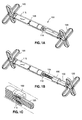
- Figure 1F illustrates the feet 120 in an extended or elongated position to allow easier implantation and removal. However, once implanted inside the patient's stomach, the feet may fold to a deployed state as shown in Figure 1G . In this state, the feet point outwards and prevent migration through the pylorus, and then the intestines. In one aspect, the length of the inner end portion 135 and outer end portion 140 may be configured to form an "X" pattern that is larger than the opening of the pylorus.
- Figure 1H illustrates the feet 120 bending, which may occur when the stomach stimulator 100 is exerting pressure on the stomach walls.
- the end portion 120 is not able to migrate through the pylorus as the inner portion 140 and the outer portion 135 contact each other and resist the end portion 120 from bending further.
- the end 120 is still too large to fit through the pylorus. While shown as three distinct states, the stomach stimulator 100 may be configured to take on any position therebetween.
- a gastrointestinal implant such as an intragastric obesity treatment device 200, may comprise a piston assembly 205, such as a telescoping tube, coupled to two atraumatic, pliable end portions, which are shown in the illustrated monument as balloon feet 210, 212.
- Balloon feet 210, 212 are not according to the invention defined in claim 1.
- the piston assembly 205 is configured to bias the balloon feet 210, 212 against the walls of a patient's stomach 202. As the balloon feet 210, 212 exert pressure against the walls of the stomach 202, the patient may experience a feeling of satiety, resulting in a reduced desire to eat, and eventually resulting in weight loss.
- the balloon 212 may exert pressure on the greater curvature of the stomach, causing the balloon 210 to exert pressure on the cardia.
- Such cardial pressure may stimulate the release of satiety-inducing hormones, thus reducing meal time food intake.
- the shape of the intragastric obesity treatment device 200 appropriately orients the balloon feet 210, 212 within the stomach 202 approximate the greater curvature and the cardia.
- the piston assembly 205 may comprise a piston 206 disposed within sleeves 207, 208.
- the piston 206 is fixed with respect to one of the sleeves 207, 208 and was the other toward or away from the first sleeve, causing the balloon feet 210, 212 similarly to move toward or away from each other.
- the piston 206 may slide within both sleeves 207, 208.
- a self-actuating lengthener 209 may be disposed within one of the sleeves 207, 208, for example, within the sleeve 208 (as illustrated in Figure 4 ), to facilitate moving the piston 206 within the sleeves 207, 208.
- the self-actuating lengthener 209 may comprise a polymer that is acid-activated.
- the self-actuating lengthener 209 may comprise a polymer bundle that is capable of expanding up to two times its original length when the polymer bundle is exposed to an acidic environment with a lower pH.
- acid-activated polymers may be referred to as stimuli sensitive polymers, and may comprise polyacrylonitrile (PAN) fibers.
- PAN fibers for acid-activated lengthener are discussed herein, it should be understood that various lengthener are contemplated within the scope of the present invention.
- all lengthener that are capable of being actuated by substances that may exist in the body, such as stomach juices, enzymes, and/or the like, are within the scope of the present invention.
- Such substances may be referred to herein as "bodily substances.”
- stomach 202 As a patient begins to eat, digestive enzymes along with hydrochloric acid (HCL) are secreted into the stomach 202, resulting in a lowered pH in the stomach 202.
- HCL hydrochloric acid
- This lowered pH causes the polymer in the lengthener 209 to expand, which in turn causes the piston assembly 205 to move the balloon feet 210, 212 away from each other to exert pressure on the stomach 202.
- the pressure stimulates the release of satiety-inducing hormones, reducing meal time food intake.
- the pH levels in the stomach 202 begin to rise, resulting in contraction of the polymer in the lengthener 209, which causes the balloon feet 210, 212 to move away from the stomach 202 walls.
- the intragastric obesity treatment device 200 comprises holes 215 to allow stomach juices to come into contact with the lengthener 209 so that it may expand and/or contract. Further, the holes 215 may permit the intragastric obesity treatment device 200 to be properly situated within the stomach 202, such that motion of the stomach juices does not substantially affect the position of the intragastric obesity treatment device 200, other than by causing the lengthener 209 to move the piston assembly 205 and the balloon feet 210, 212.
- the sleeves 207, 208 and/or the piston 206 may be hollow to allow the stomach juices to flow through the holes 215 and through the sleeves 207, 208 and/or the piston 206 to come into contact with the lengthener 209.
- the balloon feet 210, 212 may be configured to cushion the ends of the intragastric obesity treatment device 200 as the ends expand against the stomach 202 walls, to reduce the likelihood of ulceration.
- the balloon feet 210, 212 may be referred to as "balloons," this reference is for descriptive purposes only, and not to limit the structures to balloons per se. Rather, the balloon feet 210, 212 are "balloon-like" structures intended to protect the stomach 202 walls.
- the balloon feet 210, 212 may comprise compliant structures that expand and contract, such as when the balloon feet 210, 212 are filled after implantation with air, saline, and the like.
- the balloon feet 210, 212 may have thicker walls such that they substantially maintain their as-molded shape without inflation. Where the balloon feet 210, 212 maintain their shape, the holes 215 may also be placed in the balloon feet 210, 212 to allow the stomach juices to flow through the balloon feet 210, 212.
- the flexible nature of the balloon feet 210, 212 and the small diameter of the rigid piston assembly 205 allows for deployment and/or removal of the intragastric obesity treatment device 200 via a guiding tube placed through a patient's mouth, down the patient's esophagus, and into the patient's stomach 202.
- the balloon feet 210, 212 are configured to collapse and/or fold down around the piston assembly 205 to allow the intragastric obesity treatment device 200 to be inserted into and/or removed from the stomach 202 via the guiding tube in the esophagus.
- the intragastric obesity treatment device 200 may be configured to be implanted into or extracted from the stomach 202 without the use of this guiding tube.
- a fluid tube may be connected to the intragastric obesity treatment device 200 and deployed down the guiding tube through which the device 200 is inserted into or extracted from the stomach.
- This fluid tube may be coupled to one or both of the balloon feet 210, 212 (in series or in parallel -- e.g., one of the balloon feet may be connected to the other balloon via internal tubing in the piston assembly 205 ) to allow the balloon feet 210, 212 to be filled with air, saline, or other fluid.
- a syringe may be coupled to the fluid tube outside of the patient's mouth to facilitate filling or draining the balloon feet 210, 212. After implantation/extraction, both of the tubes are removed from the esophagus, resulting in a minimally invasive implantation/extraction procedure.
- balloon feet 210, 212 may be self supporting (e.g., thick walls may allow the balloon feet to maintain shape without internal pressure from added air/saline), air may be pre-extracted from the balloon feet 210, 212, creating a partial vacuum to cause the balloon feet 210, 212 to collapse around the piston assembly 205.
- a portion of the piston assembly 205 adjacent each of the balloon feet 210, 212 is relatively thin, permitting collapse of the balloon feet therearound to form a substantially consistent delivery/removal diameter.
- the fluid tube may allow the partial vacuum in the balloon feet 210, 212 to be released, causing them to expand to their self-supported shape.
- the feet 210, 212 may be, for example, an acid-resistant plastic or any other appropriate material injected with radio-opaque additive so that they may be seen with an x-ray machine during the removal procedure.
- the tubular body 205 may be constructed, for example, out of a polysulphone, polypropylene or an acid-resistant plastic material configured to resist the strong acidity of the stomach juices.
- removal of the stomach stimulator 200 may be easily performed using a standard grabber. Once the ends are folded down and the stomach stimulator 200 is compressed, the entire stomach stimulator 200 may be easily pulled up through the patient's stomach and esophagus and exit the patient's mouth.
- FIG. 5A illustrates another transoral obesity treatment device, namely the inflatable balloon device 300.
- the inflatable balloon device 300 is inflated and filled with stomach juices naturally occurring and produced in the patient's body.
- the inflatable balloon device 300 includes an inflatable layer 305 which spans almost the entire length of body 320.
- the top 310 and bottom 350 of the inflatable balloon device 300 might not be maintained within the inflatable layer 305.
- At the outer surface of the top 310 is an opening 315.
- the opening 315 may be configured to allow peristaltic pump 325 to pull stomach juices into the inflatable layer 305 to fill the balloon or to push out stomach juices from inside the inflatable layer 305 to deflate the balloon.
- the inflatable balloon device 300 may further include an aseptic band 335, a barrier 360 and a control portion 330.
- an aseptic band 335 By inflating the inflatable balloon device 300 to a volume between 0 milliliters (mL) and 1000 mL (but preferably between 400 mL and 700 mL), the balloon occupies space in the stomach decreasing the amount of space for food, and also stimulates the stomach walls when the inflatable balloon device 300 via inflation and/or migration exerts a pressure on the inner stomach walls.
- the inflatable balloon device 300 has the capacity to vary in volume and is desirably self-actuating in that the size change occurs from components within. The term, "self-actuating," however, does not exclude a remote connection to an external controller, as will be described below.
- FIG. 5B is a deconstructed version of inflatable balloon device 300.
- the inflatable layer 305 forming the "balloon" is removed to better illustrate the various other aspects of the inflatable balloon device 300.
- a portion of the body 320 of the inflatable balloon device 300 is covered by an antiseptic band 335.
- the band 335 may be a separate piece of metal attached to the body 320, or may be directly integrated into the body 320 as an exterior layer.
- the band 335 may be constructed of any material with cleansing, antiseptic qualities. In one example, silver may be used to form the band since silver has natural antiseptic qualities.
- the function of the band 335 is to passively disinfect the stomach fluid inside the inflatable layer 305.
- Figures 5C and 5D are further deconstructed versions of the inflatable balloon device of Figure 5B .
- the antiseptic band 335 is removed to better show the portion of the tubular body 320 otherwise blocked from view by the band 335.
- the body 320 may house a number of components.
- the body may contain a peristaltic pump 325, rollers 340 operating in conjunction with the pump 325, a barrier portion 360 and a control portion 330.
- the tubular body 320 may be attached to a top 310 and bottom 340.
- the tubular body 320 may include a hole 345, and the top 310 may also include a hole 315. The first hole is located at the top 315 and the second hole 355 is located on the side of the body 345.
- the stomach fluid is pumped into and out of the inflatable balloon device 300 via these two holes since one of the holes (e.g., hole 345 ) is located inside the inflatable layer 305 and the other hole (e.g., hole 315 ) is located outside the inflatable layer 305.
- the tubular body 320 is removed to better show the peristaltic pump and the control board 330.
- the control board 330 may include a processor, physical memory (e.g., a EEPROM, RAM, ROM, etc.), battery and transceiver.
- the transceiver 338 may allow the control board 330 to communicate with an external computer and receive commands and send status information such as current volume, etc.
- the control board 330 may further include a sensor 339 configured to detect a current volume of the inflatable balloon device 300.
- all the components of the control board 330 may be coupled to one another.
- the control board 330 may further include a motor (not shown) to drive the rollers 340. Alternatively, the motor may be part of the roller mechanism 340.
- the processor may drive the rollers 340 to either pump stomach fluid into the inflatable balloon device 300 thereby inflating it to a desirable volume or the processor may drive the rollers 340 to pump stomach fluid out of the inflatable balloon device 300 to deflate it to a desirable volume. More particularly, the processor may control a motor and/or a gearhead, which in turn drives the rollers 340.
- the memory may store data such as a schedule for inflating or deflating the balloon. In one aspect, the schedule may be updated, changed or interrupted by the transceiver receiving a command from an external computer.
- FIG. 5E is a close up view of the peristaltic pump 325 apparatus.
- the peristaltic pump 325 includes an external opening 315 leading out through the top of the inflatable balloon device 300, and an internal opening 345 leading out to the side of the tubular body 320 and within the inner cavity of the inflatable layer 305.
- Rollers 340 of the pump 325 are in contact with flexible tubes 365 and 375 that form a conduit between the external opening 315 and internal opening 345.
- the rollers 340 rotate in a clockwise direction, moving stomach fluid in through the inlet opening 345 as shown and through the distal tube 365 to proximal tube 375 and out external opening 315, thereby deflating the inflatable balloon device 300.
- the rollers 340 rotate in a counter-clockwise direction pulling fluid in through external opening 315, down through tube 375, up through tube 365 and out opening 345, in the opposite direction of the arrows. In this fashion the stomach fluid outside the inflatable layer 305 is moved inside the inflatable layer 305, thereby expanding the volume inside the inflatable layer 305.
- the rollers 340 may be controlled according to any of a number of methods.
- Figure 5G illustrates an example of one such method via a flow chart.
- the schedule may be a daily schedule that inflatable balloon device 300 follows. Alternatively, the schedule may be for a week, month, year and so forth.
- the target volume may be determined according to the schedule at step S365 .
- the motor may be driven to achieve the target volume.
- inflatable balloon device 300 may determine if a trigger to change the volume is detected.
- the trigger may be merely determining that the schedule dictates a changing of the volume of the device 300.
- Other triggers may include a command from an external computer to change the length of the inflatable balloon device 300.
- the external computer may issue a "min volume" command to have inflatable balloon device 300 deflate itself as much as possible.
- This command may be advantageous, for instance, when the physician is preparing to remove inflatable balloon device 300.
- the inflatable balloon device 300 may be configured to override the schedule anytime a command is received from the external computer.
- inflatable balloon device 300 may determine a new target volume and drive the pump to achieve the target volume.
- the inflatable balloon device 300 may maintain its current volume until a new trigger is detected to alter the volume.
- the volume of the balloon might not decrease beyond a certain predetermined threshold to prevent the inflatable balloon device 300 from getting lodged in the patient's pylorus.
- the top and bottom of the inflatable balloon device 300 may be attached to foldable ends similar to feet 120 of the stomach stimulator as shown in Figures 1E , 1F and 1G .
- the top and bottom of the inflatable balloon device 300 may widen outwards at the two ends, where the diameter of the top and bottom may be sufficiently large enough such that the inflatable balloon device 300 might not be able to fit through the opening of the pylorus.
- the diameter of the tubular body 320 may be 10 mm or less, and the control portion housed within the tubular body may be 8 mm or less in width, and configured to fit inside the tubular body 320.
- the insertion process for the inflatable balloon device 300 may be as simple as having the patient swallow the inflatable balloon device 300 while the inflatable balloon device 300 is in a deflated state.
- the inflatable balloon device 300 in a deflated state may be carefully inserted through the mouth of the patient, down the esophagus and into the patient's stomach by using a standard grabber.
- the removal process for the inflatable balloon device 300 may be substantially the reverse of the insertion process. After substantially deflating the inflatable balloon device 300, a standard grabber may be used to clamp onto one end of the inflatable balloon device 300 and pulled back up through the esophagus and out the patient's mouth.
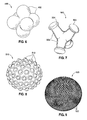
- FIGs 6 and 7 illustrate certain specific features that encourage rotational variation, and may be incorporated into the devices shown herein, in particular to the inflatable balloon device 300 of Figures 5A-5G .
- an intragastric obesity treatment device 490 essentially comprises an aggregation of spheres 492.
- the overall exterior shape of the device is somewhat spherical, encouraging rotation.
- the outwardly projecting spheres that make up the device contact the stomach wall at different locations as the device rotates.
- a device 500 comprises a plurality of outwardly projecting legs 502 terminating in rounded or bulbous feet 504.
- the device 500 rotates relatively easily within the stomach, especially upon peristaltic motion, and the separated legs 502 and feet 504 therefore contact the stomach wall at different locations on a constantly changing basis.
- the devices 490, 500 of Figures 6 and 7 may also serve to temporarily block the pylorus and slow gastric emptying.
- FIG. 8 illustrates a spherical intragastric device 510 having numerous external bumps 512 projecting outward therefrom. These bumps 512 separately contact the inner walls of the stomach, potentially increasing the stimulation to the surrounding satiety-sensing nerves.
- FIG 9 Another example of exterior stimulation features is seen in Figure 9 , where an intragastric device 520 formed as a sphere features a multitude of small pins or flagella 522 extending outward therefrom.
- the two embodiments shown in Figures 8 and 9 rotate freely within the stomach, such as the inflatable balloon device 300, and that the bumps 512 or flagella 522 may be provided in a non-uniform distribution so as to take advantage of the benefits of the rotational variation described above. That is, a regular array of such exterior features may stimulate the stomach wall more than a smooth surface, but also providing a non-uniform distribution will create different sensations on a constantly changing basis.
- the bumps 512 or flagella 522 may also be provided on the atraumatic feet 120 of the embodiment in Figures 1A-1H or the balloon feet 210, 212 of Figures 2-4 , to facilitate nerve stimulation.
- An alternative intragastric device may include recesses or dimples extending inward from the surface of the intragastric device, much like the reverse of the outward bumps in Figure 8 .
- the intragastric device may have a surface comprised of recesses between flat portions. A plurality of such recesses may be equally spaced apart on the outer surface. The recesses may not contact each other, and may be of equal heights and diameters.
- the recesses may employ a thinner wall. For example, if the flat portions have a wall thickness of 20 millimeters, the recesses may have a wall thickness of 10 millimeters. With a thinner wall, the recesses may be more susceptible to larger strains.
- the implantable devices described herein will be subjected to clinical testing in humans.
- the devices are intended to treat obesity, which is variously defined by different medical authorities.
- overweight and “obese” are labels for ranges of weight that are greater than what is generally considered healthy for a given height.
- the terms also identify ranges of weight that have been shown to increase the likelihood of certain diseases and other health problems.
- Applicants propose implanting the devices as described herein into a clinical survey group of obese patients in order to monitor weight loss.
- Silicone materials used include 3206 silicone for any shells, inflatable structures, or otherwise flexible hollow structures. Any fill valves will be made from 4850 silicone with 6% BaSo 4 . Tubular structures or other flexible conduits will be made from silicone rubber as defined by the Food and Drug Administration (FDA) in the Code of Federal Regulations (CFR) Title 21 Section 177.2600.
- FDA Food and Drug Administration
- the device is intended to be implanted transorally via endoscope into the corpus of the stomach.
- Implantation of the medical devices will occur via endoscopy.
- Nasal/Respiratory administration of oxygen and isoflurane to be used during surgical procedures to maintain anesthesia as necessary.
Description
- The present invention generally relates to medical implants and uses thereof for treating obesity and/or obesity-related diseases and, more specifically, to transorally-delivered devices designed to occupy space within a stomach and/or stimulate the stomach wall.
- Over the last 50 years, obesity has been increasing at an alarming rate and is now recognized by leading government health authorities, such as the Centers for Disease Control (CDC) and National Institutes of Health (NIH), as a disease. In the United States alone, obesity affects more than 60 million individuals and is considered the second leading cause of preventable death. Worldwide, approximately 1.6 billion adults are overweight, and it is estimated that obesity affects at least 400 million adults.
- Obesity is caused by a wide range of factors including genetics, metabolic disorders, physical and psychological issues, lifestyle, and poor nutrition. Millions of obese and overweight individuals first turn to diet, fitness and medication to lose weight; however, these efforts alone are often not enough to keep weight at a level that is optimal for good health. Surgery is another increasingly viable alternative for those with a Body Mass Index (BMI) of greater than 40. In fact, the number of bariatric surgeries in the United States is projected to reach approximately 400,000 annually by 2010.
- Examples of surgical methods and devices used to treat obesity include the The LAP-BAND® (Allergan, Inc., Irvine, CA) gastric band and the LAP-BAND AP® (Allergan, Inc., Irvine, CA). However, surgery might not be an option for every obese individual; for certain patients, non-surgical therapies or minimal-surgery options are more effective or appropriate.
- For example, intragastric balloons may be utilized as non-surgical or minimal-surgery means for treating obesity. One such inflatable intragastric balloon is described in
U.S. Pat. No. 5,084,061 and is commercially available as the BioEnterics Intragastric Balloon System (sold under the BIB® System). These devices are designed to provide therapy for moderately obese individuals who need to shed pounds in preparation for surgery, or as part of a dietary or behavioral modification program. - The BIB® System, for example, comprises a silicone elastomer intragastric balloon that is inserted into the stomach and filled with fluid. Conventionally, the balloons are placed in the stomach in an empty or deflated state and thereafter filled (fully or partially) with a suitable fluid. The balloon occupies space in the stomach, thereby leaving less room available for food and creating a feeling of satiety for the patient. Clinical results with these devices show that for many obese patients, the intragastric balloons significantly help to control appetite and accomplish weight loss.
- Placement of such balloons is temporary, and such balloons are typically removed after about six months. One means of removing the balloon is to deflate it by puncturing the balloon, and either aspirating the contents of the balloon or allowing the fluid to pass into the patient's stomach. Alternatively, if the balloon is left in place beyond its designed lifetime, the acids present in a patient's stomach may erode the balloon to the point where it self-deflates. When this occurs, the deflated balloon may pass naturally through the patient's digestive system and be expelled through the bowel. For instance, McGhan,
U.S. Pat. No. 6,733,512 , describes a self-deflating intragastric balloon that includes a biodegradable inflation valve. After a certain residence time in the stomach, the valve starts to leak and eventually the balloon deflates and passes though the patient's digestive tract. - Despite the advances in the design of intragastric balloons, there remains a need for improved transoral obesity treatment devices.
-
US 2010/0049224 (A1 ) discloses an intragastric implant comprising an anchor and a therapeutic device or a diagnostic device. The anchor is adapted to extend between the fundus and the pyloric valve of a stomach, to be retained without attachment to the stomach wall, and to anchor the device within the stomach with a relatively stable position and orientation. The therapeutic or diagnostic device is adapted to extend from the esophagus or stomach to the intestines or stomach. The therapeutic or diagnostic device, when extending into the esophagus, will be slidably received through the gastroesophageal junction and, when extending into the intestines, will be slidably received in the pyloric valve. -
WO 2007/092390 (A2 ) discloses devices and methods for applying gastrointestinal stimulation include implanting a stimulation device including a body with at least one expandable portion and a bridging portion and at least one stimulation member in the gastrointestinal tract. The at least one stimulation member includes one or more energy delivery members, one or more sensors, or a combination of both. The body maintains the device within the gastrointestinal space, and preferentially within the pyloric portion of the patient's stomach, and prevents passage of the device from the gastrointestinal space, but is not rigidly anchored or affixed to the gastrointestinal wall tissue. -
WO 2011/049651 (A1 ) discloses a bariatric device for use in inducing weight loss, comprising a cardiac element, a pyloric element, and a connecting element between the two other elements, wherein the connecting element provides structure between the cardiac and pyloric elements, keeping them largely in place and at least intermittently touching and applying pressure to the stomach's cardiac, adjacent fundic and pyloric regions, respectively, which produces a satiety signal to the user, giving the recipient a feeling of fullness and reducing his or her hunger feelings. In an alternative embodiment, the pyloric and connecting elements may be replaced with a positioning element, which keeps the cardiac element in its relative position by pushing against various structures in the stomach. In any of the embodiments the bariatric device may be made from multiple sizes or adjustable, either manually, automatically or remotely, to optimally size and/or position the device to produce the desired satiety signals and weight loss. This document is prior art under Article 54(3) EPC. - Transoral obesity treatment devices generally promote a feeling of satiety in the patient by contacting the insides of the stomach wall, reducing the space in the stomach, or otherwise reducing the amount of food consumed or digested by the patient. The devices have the capacity to vary in size and are desirably self-actuating in that they change shape and/or volume using internal motors or actuators. The changing character of the devices helps prevent the person's stomach from compensating for the implant, such as sometimes happens with static intragastric devices.
- In addition, transoral obesity treatment devices generally allow for easy and quick placement and removal. Surgery is usually not required or very minimal. In one aspect, the transoral obesity treatment devices are placed in the patient through the mouth, passing the esophagus and reaching the destination, usually in the stomach region. In most instances, the transoral obesity treatment device does not require suturing or stapling to the esophageal or stomach wall, and remains inside the patient's body for a lengthy period of time (e.g., months or years) before removal.
- In one embodiment, the transoral obesity treatment device may be a stomach stimulator, which may fight obesity by stimulating the stomach walls of the patient and occupying space inside the stomach. The stomach stimulator may be an electromechanical device comprising a telescoping body and expandable ends. The ends may be configured to exert a pressure on the inner stomach walls of the patient and, when in the expanded state, prevent the stomach stimulator from entering the patient's intestines. The telescoping body shortens or lengthens the stomach stimulator, either randomly or in accordance with a predefined schedule, such that the patient's body cannot compensate. Studies have shown that obesity may be more effectively reduced when a patient's body cannot compensate to the obesity device.
- According to the invention defined in claim 1, a system for treating obesity by applying a pressure to the patient's stomach comprises a central elongated body having an adjustable length. Two collapsible atraumatic feet on opposite ends of the elongated body are each configured to exert pressure on the patient's stomach when in a deployed position. An actuator within the central elongated body adjusts the length of the body and simultaneously the distance between the atraumatic feet. The two collapsible atraumatic feet comprise an array of living hinges that may be unfolded to an elongated delivery configuration and folded outward to a deployed configuration. The array of living hinges may be in an X-shape. The actuator may comprise an electronic motor, and further may include a control circuit board having a battery and a memory. The actuator control circuit board further may have a transceiver, and the system further includes a remote control for instructing the motor from outside the patient's body. In one embodiment, the actuator comprises a telescoping screw driven by the motor. Alternatively, the actuator comprises a polymer element that is acid-activated to lengthen in a highly acidic environment, and the central elongated body includes through holes for exposing the polymer element to the stomach environment. The central elongated body may comprise a series of telescoping tubular members having apertures along their lengths. In one embodiment, the atraumatic feet include uneven external surface stimulation features.
- The following detailed descriptions are given by way of example, but not intended to limit the scope of the disclosure solely to the specific embodiments described herein. The device of
figure 1 forms an embodiment of this invention. The devices offigures 2 to 9 do not from embodiments. The devices disclosed herein may be understood in conjunction with the accompanying drawings in which: -
Figure 1A illustrates a perspective view of an elongated stomach stimulator having soft, folded feet and a variable length. -
Figure 1B illustrates a perspective view of the stomach stimulator ofFigure 1A in an extended state. -
Figure 1C illustrates a close up view of a portion of the stomach stimulator. -
Figure 1D illustrates a control board for the stomach stimulator. -
Figure 1E illustrates a flow chart for controlling the stomach stimulator ofFigure 1A . -
Figure 1F illustrates a close up view of an end portion of a stomach stimulator in a folded state. -
Figure 1G illustrates a close up view of an end portion of a stomach stimulator in a deployed or unfolded state. -
Figure 1H illustrates a close up view of an end portion of a stomach stimulator in a pressuring state. -
Figure 2 illustrates a side view of an intragastric obesity treatment device with a piston in a patient's stomach. -
Figure 3 illustrates a perspective view of an intragastric obesity treatment device with a piston. -
Figure 4 illustrates a sectional view of an intragastric obesity treatment device with a piston and a motor in accordance with an embodiment of the present invention. -
Figure 5A illustrates a perspective view of a balloon device with the balloon inflated. -
Figure 5B illustrates a balloon device with a silver band. -
Figure 5C illustrates a perspective view of a balloon device without the outer balloon shell. -
Figure 5D illustrates a balloon device with the outer body removed. -
Figure 5E illustrates a close up view of the peristaltic pump of the balloon device. -
Figure 5F shows an electronic controller for operating the peristaltic pump of an intragastric balloon device of the three-dimensionally orthogonal intragastric spring device; -
Figure 5G illustrates a flow chart for controlling the balloon device. -
Figures 6 and 7 illustrate intragastric devices that encourage rotational variation. -
Figures 8 and 9 illustrate intragastric devices that both encourage rotational variation and provide additional stomach cavity stimulation. - Persons skilled in the art will readily appreciate that various aspects of the disclosure may be realized by any number of methods and devices configured to perform the intended functions. Stated differently, other methods and devices may be incorporated herein to perform the intended functions. It should also be noted that the drawing Figures referred to herein are not all drawn to scale, but may be exaggerated to illustrate various aspects of the invention, and in that regard, the drawing Figures should not be construed as limiting. Finally, although the present disclosure may be described in connection with various medical principles and beliefs, the present disclosure should not be bound by theory.
- By way of example, the present disclosure will reference certain transoral obesity treatment devices. Nevertheless, persons skilled in the art will readily appreciate that certain aspects of the present disclosure advantageously may be applied to one of the numerous varieties of transoral obesity treatment devices other than those disclosed herein.
- In one aspect, these transoral obesity treatment devices described herein are intended to be placed inside the patient, transorally and without invasive surgery, without associated patient risks of invasive surgery and without substantial patient discomfort. Recovery time may be minimal as no extensive tissue healing is required. The life span of these transoral obesity treatment devices may be material-dependent upon long-term survivability within an acidic stomach, but is intended to last one year or longer.
-
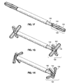
Figure 1A illustrates a first embodiment of a variable sized transoral obesity treatment device, namely a variable-length stomach stimulator 100. The stomach stimulator 100 may include a tubular body 105 (shown in phantom to reveal the inner components), two oppositeatraumatic feet 120, acontrol portion 115, and O-ring seals 110 to prevent stomach juices (e.g., acids) from reaching and corrupting or destroying thecontrol portion 115. The stomach stimulator 100 may reduce appetite as thefeet 120 contact and pressure the inside of the patient's stomach walls, thereby affecting nerves and causing early feelings of satiety. In one aspect, the entire stomach stimulator including the feet 120 (in a folded state) may be no larger than 10 millimeters (mm) in diameter, thereby easily passing transorally into the patient's mouth, through the esophagus and into the patient's stomach. - In one aspect, the
stomach stimulator 100 may be configured to telescope to varying lengths. For example,Figure 1B illustrates the stomach stimulator ofFigure 1A in an extended position. Theextension portion 125 may be a screw-like device that telescopically shortens in the direction of thecontrol portion 115 and telescopically lengthens in the direction away from thecontrol portion 115. As shown, theextension portion 125 attaches to ashaft portion 130 such that when the extension portion telescopically lengthens, a part of the intermediate portion extends outside thebody 105, thereby "extending" the length of thestomach stimulator 100. Thestomach stimulator 100 has the capacity to vary in length and is desirably self-actuating in that the size change occurs from components within. The term, "self-actuating," however, does not exclude a remote connection to an external controller, as will be described below. -
Figure 1C illustrates a close up view of theextension portion 125 and the dual O-ring seals 110 configured to prevent stomach acid from entering thecontrol portion 115. Thecontrol portion 115 may include an implantable motor and gearhead assembly (not shown) configured to drive theextension portion 125. In one aspect, the motor and gearhead assembly may be controlled by an electronic controller also housed in thecontrol portion 115. -
Figure 1D illustrates acontrol board 160 for thestomach stimulator 100 that includes aprocessor 165, physical memory (e.g., a EEPROM, RAM, ROM, etc.) 170,battery 175 andtransceiver 180. The memory may store data such as a schedule for lengthening or shortening thestimulator 100. Thetransceiver 180 may allow thecontrol board 160 to communicate with an external computer and receive commands and send status information such as current length of thestimulator 100, etc. Thecontrol board 160 may further include asensor 185 configured to detect a current length of thestimulator 100. Thecontrol board 160 desirably controls the motor and gearhead assembly (not shown) to drive the telescoping screw 125 (Fig. 1B ) to either lengthen or shorten thestimulator 100. In one aspect, the schedule may be updated, changed or interrupted by the transceiver receiving a command from an external computer. In another example, the transceiver may receive a new or updated target stimulator length schedule to assist thestomach stimulator 100 in determining when to adjust the length of the extension portion and the target length to adjust it to. By virtue of thetransceiver 180, thestimulator 100 can be controlled externally by hand-held radiofrequency remote controller (not shown). Thecontrol board 160 communicates with the remote control unit, and also may contain program information that drives the motor at various random or pre-set distances and at random or preset intervals, causing one end of thestimulator 100 to telescope in and out. The randomness of the telescoping length provides varying pressure, so the patient's body is not likely to compensate, or to adapt to any one typical stomach size. -
Figure 1E illustrates a flow chart of one example of how thestomach stimulator 100 may function. Initially, when thestomach stimulator 100 is first deployed in the patient's stomach, thestomach stimulator 100 may read a schedule instructing the different lengths that the stimulator may adjust to and at which times at step S160. In one example, the schedule may be a daily schedule that thestomach stimulator 100 follows. Alternatively, the schedule may be for a week, month, year and so forth. After the schedule is read in step S160, the target length may be determined according to the schedule at step S165. At step S170, the motor may be driven to achieve the target length. At step S175, thestomach stimulator 100 may determine if a trigger to change the length is detected. For example, the trigger may be merely determining that the schedule dictates a changing of the length of thestomach stimulator 100. Other triggers may include a command from the external computer to change the length of thestomach stimulator 100. In one aspect, the external computer may issue a "max short" command to have thestomach stimulator 100 shorten itself as much as possible. This command may be advantageous, for instance, when the physician is preparing to remove the stomach stimulator. The stomach stimulator 100 may be configured to override the schedule anytime a command is received from the external computer. In response to the trigger, the stomach stimulator may determine a new target length and drive the motor to achieve the target length. However, if at step S175 no trigger is detected, thestomach stimulator 100 may maintain its current length until a new trigger is detected to alter the length. - In one aspect, changing the length of the
stomach stimulator 100 may be advantageous to prevent the patient's body from compensating or adapting to the presence of thestomach stimulator 100. It is thought that if the body is allowed to adapt to thestomach stimulator 100, weight gain due to body compensation may occur decreasing the effectiveness of thestomach stimulator 100. Some clinical indications are that patients adapt to introduction of gastrointestinal implants normally within the first few months of surgery, so early weight gain due to compensation will likely be avoided with the randomly changingstimulator 100. In this sense, by constantly and unpredictably changing the lengths of thestomach stimulator 100, the patient's body cannot adapt effectively, thus promoting weight loss more effectively. In one alternative, the stomach stimulator may be configured to continuously telescope (e.g., never stopping to maintain a particular length). As the stomach muscles churn their contents, thestomach stimulator 100 will essentially randomly shift the point at which pressure is exerted from within the stomach, thus helping to prevent physiological compensation by the stomach for the object within. - In addition, the changing lengths may further have an additional benefit. The pressure exerted by the feet (e.g.,
feet 120 ofFigure 1A ) on the inside of the stomach walls may cause early feelings of satiety. Thefeet 120 are configured to be atraumatic, in that they are soft and pliable. Thefeet 120 are desirably formed as an array of fingers of a soft polymer, each preferably having thinned regions so as to function like living hinges. More particularly, each of the spokes of the "X" shapedfeet 120 has a rectangular cross-section to facilitate bending in one plane, and thinned regions at three points: where it connects to thestimulator 100, where it connects to the other spokes along an axis of the device, and at a mid-portion which forms the outermost end of each of the spokes in the deployed configuration seen inFigure 1G . Of course other configurations for the atraumatic feet are contemplated, such as rounded pillows, cups, or the like. Thefeet 120 also may have a radio-opaque additive molded therein so that they can be seen with X-ray, such as during a removal procedure. -
Figure 1F illustrates thefeet 120 in an extended or elongated position to allow easier implantation and removal. However, once implanted inside the patient's stomach, the feet may fold to a deployed state as shown inFigure 1G . In this state, the feet point outwards and prevent migration through the pylorus, and then the intestines. In one aspect, the length of theinner end portion 135 andouter end portion 140 may be configured to form an "X" pattern that is larger than the opening of the pylorus.Figure 1H illustrates thefeet 120 bending, which may occur when thestomach stimulator 100 is exerting pressure on the stomach walls. Advantageously, even in this pressuring state, theend portion 120 is not able to migrate through the pylorus as theinner portion 140 and theouter portion 135 contact each other and resist theend portion 120 from bending further. In other words, even at the pressuring state, theend 120 is still too large to fit through the pylorus. While shown as three distinct states, thestomach stimulator 100 may be configured to take on any position therebetween. - With reference to
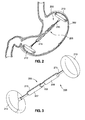
Figures 2-4 , a gastrointestinal implant, such as an intragastricobesity treatment device 200, may comprise apiston assembly 205, such as a telescoping tube, coupled to two atraumatic, pliable end portions, which are shown in the illustrated monument asballoon feet Balloon feet piston assembly 205 is configured to bias theballoon feet stomach 202. As theballoon feet stomach 202, the patient may experience a feeling of satiety, resulting in a reduced desire to eat, and eventually resulting in weight loss. For example, theballoon 212 may exert pressure on the greater curvature of the stomach, causing theballoon 210 to exert pressure on the cardia. Such cardial pressure may stimulate the release of satiety-inducing hormones, thus reducing meal time food intake. In various embodiments, the shape of the intragastricobesity treatment device 200 appropriately orients theballoon feet stomach 202 approximate the greater curvature and the cardia. - As seen in
Figure 3 , thepiston assembly 205 may comprise apiston 206 disposed withinsleeves piston 206 is fixed with respect to one of thesleeves balloon feet piston 206 may slide within bothsleeves - As seen in the cross-section of
Figure 4 , a self-actuating lengthener 209 may be disposed within one of thesleeves Figure 4 ), to facilitate moving thepiston 206 within thesleeves actuating lengthener 209 may comprise a polymer that is acid-activated. For example, the self-actuating lengthener 209 may comprise a polymer bundle that is capable of expanding up to two times its original length when the polymer bundle is exposed to an acidic environment with a lower pH. Such acid-activated polymers may be referred to as stimuli sensitive polymers, and may comprise polyacrylonitrile (PAN) fibers. - Such polymers are disclosed in the following documents,: Anasuya Sahoo, et al., "Effect of copolymer architecture on the response of pH sensitive fibers based on acrylonitrile and acrylic acid," European Polymer Journal 43 (2007), 1065-1076. Kiyoung Choe and Kwang J. Kim, "Polyacrylonitrile linear actuators: Chemomechanical and electro-chemomechanical properties," Sensors and Actuators A 126 (2006), 165-172. R, Samatham, et al., "Electrospun nanoscale polyacrylonitrile artificial muscle," Smart Materials and Structures 15 (2006), N152-N156. B. Tondu, et al., "A pH-activated artificial muscle using the McKibben-type braided structure," Sensors and Actuatos A 150 (2009), 124-130. Ping An Song, et al., "A pH-sensitive Modified Polyacrylamide Hydrogel," Chinese Chemical Letters, Vol. 17, No. 3 (2006) 399-402.
- Although PAN fibers for acid-activated lengthener are discussed herein, it should be understood that various lengthener are contemplated within the scope of the present invention. For example, all lengthener that are capable of being actuated by substances that may exist in the body, such as stomach juices, enzymes, and/or the like, are within the scope of the present invention. Such substances may be referred to herein as "bodily substances."
- Accordingly, as a patient begins to eat, digestive enzymes along with hydrochloric acid (HCL) are secreted into the
stomach 202, resulting in a lowered pH in thestomach 202. This lowered pH causes the polymer in thelengthener 209 to expand, which in turn causes thepiston assembly 205 to move theballoon feet stomach 202. The pressure stimulates the release of satiety-inducing hormones, reducing meal time food intake. As the patient stops eating and digestion progresses, the pH levels in thestomach 202 begin to rise, resulting in contraction of the polymer in thelengthener 209, which causes theballoon feet stomach 202 walls. - With continued reference to
Figures 2-4 , the intragastricobesity treatment device 200 comprisesholes 215 to allow stomach juices to come into contact with thelengthener 209 so that it may expand and/or contract. Further, theholes 215 may permit the intragastricobesity treatment device 200 to be properly situated within thestomach 202, such that motion of the stomach juices does not substantially affect the position of the intragastricobesity treatment device 200, other than by causing thelengthener 209 to move thepiston assembly 205 and theballoon feet sleeves piston 206 may be hollow to allow the stomach juices to flow through theholes 215 and through thesleeves piston 206 to come into contact with thelengthener 209. - The
balloon feet obesity treatment device 200 as the ends expand against thestomach 202 walls, to reduce the likelihood of ulceration. Although theballoon feet balloon feet stomach 202 walls. For example, theballoon feet balloon feet balloon feet balloon feet holes 215 may also be placed in theballoon feet balloon feet - The flexible nature of the
balloon feet rigid piston assembly 205 allows for deployment and/or removal of the intragastricobesity treatment device 200 via a guiding tube placed through a patient's mouth, down the patient's esophagus, and into the patient'sstomach 202. Theballoon feet piston assembly 205 to allow the intragastricobesity treatment device 200 to be inserted into and/or removed from thestomach 202 via the guiding tube in the esophagus. Alternatively, the intragastricobesity treatment device 200 may be configured to be implanted into or extracted from thestomach 202 without the use of this guiding tube. - Where the
balloon feet obesity treatment device 200 and deployed down the guiding tube through which thedevice 200 is inserted into or extracted from the stomach. This fluid tube may be coupled to one or both of theballoon feet 210, 212 (in series or in parallel -- e.g., one of the balloon feet may be connected to the other balloon via internal tubing in the piston assembly 205) to allow theballoon feet balloon feet - Where the
balloon feet balloon feet balloon feet piston assembly 205. In this respect, a portion of thepiston assembly 205 adjacent each of theballoon feet obesity treatment device 200 is implanted in the stomach, the fluid tube may allow the partial vacuum in theballoon feet - Regardless of the
stomach stimulator 200, thefeet tubular body 205 may be constructed, for example, out of a polysulphone, polypropylene or an acid-resistant plastic material configured to resist the strong acidity of the stomach juices. - In another aspect, removal of the
stomach stimulator 200 may be easily performed using a standard grabber. Once the ends are folded down and thestomach stimulator 200 is compressed, theentire stomach stimulator 200 may be easily pulled up through the patient's stomach and esophagus and exit the patient's mouth. -
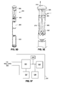
Figure 5A illustrates another transoral obesity treatment device, namely theinflatable balloon device 300. As shown, theinflatable balloon device 300 is inflated and filled with stomach juices naturally occurring and produced in the patient's body. Theinflatable balloon device 300 includes aninflatable layer 305 which spans almost the entire length ofbody 320. In one aspect, the top 310 andbottom 350 of theinflatable balloon device 300 might not be maintained within theinflatable layer 305. At the outer surface of the top 310 is anopening 315. Theopening 315 may be configured to allowperistaltic pump 325 to pull stomach juices into theinflatable layer 305 to fill the balloon or to push out stomach juices from inside theinflatable layer 305 to deflate the balloon. Theinflatable balloon device 300 may further include anaseptic band 335, abarrier 360 and acontrol portion 330. By inflating theinflatable balloon device 300 to a volume between 0 milliliters (mL) and 1000 mL (but preferably between 400 mL and 700 mL), the balloon occupies space in the stomach decreasing the amount of space for food, and also stimulates the stomach walls when theinflatable balloon device 300 via inflation and/or migration exerts a pressure on the inner stomach walls. Theinflatable balloon device 300 has the capacity to vary in volume and is desirably self-actuating in that the size change occurs from components within. The term, "self-actuating," however, does not exclude a remote connection to an external controller, as will be described below. -
Figure 5B is a deconstructed version ofinflatable balloon device 300. In this view, theinflatable layer 305 forming the "balloon" is removed to better illustrate the various other aspects of theinflatable balloon device 300. Here, a portion of thebody 320 of theinflatable balloon device 300 is covered by anantiseptic band 335. Theband 335 may be a separate piece of metal attached to thebody 320, or may be directly integrated into thebody 320 as an exterior layer. Theband 335 may be constructed of any material with cleansing, antiseptic qualities. In one example, silver may be used to form the band since silver has natural antiseptic qualities. The function of theband 335 is to passively disinfect the stomach fluid inside theinflatable layer 305. -
Figures 5C and5D are further deconstructed versions of the inflatable balloon device ofFigure 5B . Here, theantiseptic band 335 is removed to better show the portion of thetubular body 320 otherwise blocked from view by theband 335. As shown, thebody 320 may house a number of components. For example, the body may contain aperistaltic pump 325,rollers 340 operating in conjunction with thepump 325, abarrier portion 360 and acontrol portion 330. Thetubular body 320 may be attached to a top 310 andbottom 340. Thetubular body 320 may include ahole 345, and the top 310 may also include ahole 315. The first hole is located at the top 315 and the second hole 355 is located on the side of thebody 345. The stomach fluid is pumped into and out of theinflatable balloon device 300 via these two holes since one of the holes (e.g., hole 345) is located inside theinflatable layer 305 and the other hole (e.g., hole 315) is located outside theinflatable layer 305. InFigure 5D thetubular body 320 is removed to better show the peristaltic pump and thecontrol board 330. - As shown in
Figure 5F , thecontrol board 330 may include a processor, physical memory (e.g., a EEPROM, RAM, ROM, etc.), battery and transceiver. Thetransceiver 338 may allow thecontrol board 330 to communicate with an external computer and receive commands and send status information such as current volume, etc. Thecontrol board 330 may further include asensor 339 configured to detect a current volume of theinflatable balloon device 300. In one embodiment, all the components of thecontrol board 330 may be coupled to one another. In one embodiment, thecontrol board 330 may further include a motor (not shown) to drive therollers 340. Alternatively, the motor may be part of theroller mechanism 340. Regardless, the processor may drive therollers 340 to either pump stomach fluid into theinflatable balloon device 300 thereby inflating it to a desirable volume or the processor may drive therollers 340 to pump stomach fluid out of theinflatable balloon device 300 to deflate it to a desirable volume. More particularly, the processor may control a motor and/or a gearhead, which in turn drives therollers 340. The memory may store data such as a schedule for inflating or deflating the balloon. In one aspect, the schedule may be updated, changed or interrupted by the transceiver receiving a command from an external computer. -
Figure 5E is a close up view of theperistaltic pump 325 apparatus. As shown, theperistaltic pump 325 includes anexternal opening 315 leading out through the top of theinflatable balloon device 300, and aninternal opening 345 leading out to the side of thetubular body 320 and within the inner cavity of theinflatable layer 305.Rollers 340 of thepump 325 are in contact withflexible tubes external opening 315 andinternal opening 345. - In operation, the
rollers 340 rotate in a clockwise direction, moving stomach fluid in through the inlet opening 345 as shown and through thedistal tube 365 toproximal tube 375 and outexternal opening 315, thereby deflating theinflatable balloon device 300. To inflate theinflatable balloon device 300, therollers 340 rotate in a counter-clockwise direction pulling fluid in throughexternal opening 315, down throughtube 375, up throughtube 365 and outopening 345, in the opposite direction of the arrows. In this fashion the stomach fluid outside theinflatable layer 305 is moved inside theinflatable layer 305, thereby expanding the volume inside theinflatable layer 305. - The
rollers 340 may be controlled according to any of a number of methods.Figure 5G illustrates an example of one such method via a flow chart. Initially, when theinflatable balloon device 300 is first deployed in the patient's stomach,inflatable balloon device 300 may read a schedule instructing the different volumes thatinflatable balloon device 300 may adjust to and at which times at step S360. In one example, the schedule may be a daily schedule thatinflatable balloon device 300 follows. Alternatively, the schedule may be for a week, month, year and so forth. After the schedule is read in step S360, the target volume may be determined according to the schedule at step S365. At step S370, the motor may be driven to achieve the target volume. At step S375,inflatable balloon device 300 may determine if a trigger to change the volume is detected. For example, the trigger may be merely determining that the schedule dictates a changing of the volume of thedevice 300. Other triggers may include a command from an external computer to change the length of theinflatable balloon device 300. - In one aspect, the external computer may issue a "min volume" command to have
inflatable balloon device 300 deflate itself as much as possible. This command may be advantageous, for instance, when the physician is preparing to removeinflatable balloon device 300. Theinflatable balloon device 300 may be configured to override the schedule anytime a command is received from the external computer. Referring back toFigure 5F , in response to the trigger,inflatable balloon device 300 may determine a new target volume and drive the pump to achieve the target volume. However, if at step S375, no trigger is detected, theinflatable balloon device 300 may maintain its current volume until a new trigger is detected to alter the volume. - In one aspect, the volume of the balloon might not decrease beyond a certain predetermined threshold to prevent the
inflatable balloon device 300 from getting lodged in the patient's pylorus. - In an embodiment of the invention, the top and bottom of the
inflatable balloon device 300 may be attached to foldable ends similar tofeet 120 of the stomach stimulator as shown inFigures 1E ,1F and 1G . In another alternative, the top and bottom of theinflatable balloon device 300 may widen outwards at the two ends, where the diameter of the top and bottom may be sufficiently large enough such that theinflatable balloon device 300 might not be able to fit through the opening of the pylorus. - Accordingly, with or without the foldable feet, the diameter of the
tubular body 320 may be 10 mm or less, and the control portion housed within the tubular body may be 8 mm or less in width, and configured to fit inside thetubular body 320. - The insertion process for the
inflatable balloon device 300 may be as simple as having the patient swallow theinflatable balloon device 300 while theinflatable balloon device 300 is in a deflated state. Alternatively, theinflatable balloon device 300 in a deflated state may be carefully inserted through the mouth of the patient, down the esophagus and into the patient's stomach by using a standard grabber. - The removal process for the
inflatable balloon device 300 may be substantially the reverse of the insertion process. After substantially deflating theinflatable balloon device 300, a standard grabber may be used to clamp onto one end of theinflatable balloon device 300 and pulled back up through the esophagus and out the patient's mouth. -
Figures 6 and 7 illustrate certain specific features that encourage rotational variation, and may be incorporated into the devices shown herein, in particular to theinflatable balloon device 300 ofFigures 5A-5G . InFigure 6 , an intragastricobesity treatment device 490 essentially comprises an aggregation ofspheres 492. The overall exterior shape of the device is somewhat spherical, encouraging rotation. However, the outwardly projecting spheres that make up the device contact the stomach wall at different locations as the device rotates. InFigure 7 , adevice 500 comprises a plurality of outwardly projectinglegs 502 terminating in rounded orbulbous feet 504. Again, thedevice 500 rotates relatively easily within the stomach, especially upon peristaltic motion, and the separatedlegs 502 andfeet 504 therefore contact the stomach wall at different locations on a constantly changing basis. Thedevices Figures 6 and 7 may also serve to temporarily block the pylorus and slow gastric emptying. These features can be utilized in a device that looks like thedevice 500, or can be added to a number of the embodiments described herein, such as theinflatable balloon device 300. - Another option for a number of the intragastric devices disclosed herein is to add uneven external surface stimulation features, such as any raised or depressed geometry which act to stimulate certain portions of the stomach walls. Such features may be particularly effective for those embodiments which stimulate the cardia. For instance,
Figure 8 illustrates a sphericalintragastric device 510 having numerousexternal bumps 512 projecting outward therefrom. Thesebumps 512 separately contact the inner walls of the stomach, potentially increasing the stimulation to the surrounding satiety-sensing nerves. Another example of exterior stimulation features is seen inFigure 9 , where anintragastric device 520 formed as a sphere features a multitude of small pins orflagella 522 extending outward therefrom. It should be noted that the two embodiments shown inFigures 8 and 9 rotate freely within the stomach, such as theinflatable balloon device 300, and that thebumps 512 orflagella 522 may be provided in a non-uniform distribution so as to take advantage of the benefits of the rotational variation described above. That is, a regular array of such exterior features may stimulate the stomach wall more than a smooth surface, but also providing a non-uniform distribution will create different sensations on a constantly changing basis. Thebumps 512 orflagella 522 may also be provided on theatraumatic feet 120 of the embodiment inFigures 1A-1H or theballoon feet Figures 2-4 , to facilitate nerve stimulation. - An alternative intragastric device may include recesses or dimples extending inward from the surface of the intragastric device, much like the reverse of the outward bumps in
Figure 8 . For instance, the intragastric device may have a surface comprised of recesses between flat portions. A plurality of such recesses may be equally spaced apart on the outer surface. The recesses may not contact each other, and may be of equal heights and diameters. In addition to being depressed, the recesses may employ a thinner wall. For example, if the flat portions have a wall thickness of 20 millimeters, the recesses may have a wall thickness of 10 millimeters. With a thinner wall, the recesses may be more susceptible to larger strains. - The implantable devices described herein will be subjected to clinical testing in humans. The devices are intended to treat obesity, which is variously defined by different medical authorities. In general, the terms "overweight" and "obese" are labels for ranges of weight that are greater than what is generally considered healthy for a given height. The terms also identify ranges of weight that have been shown to increase the likelihood of certain diseases and other health problems. Applicants propose implanting the devices as described herein into a clinical survey group of obese patients in order to monitor weight loss.
- The clinical studies will utilize the devices described above in conjunction with the following parameters.
- Silicone materials used include 3206 silicone for any shells, inflatable structures, or otherwise flexible hollow structures. Any fill valves will be made from 4850 silicone with 6% BaSo4. Tubular structures or other flexible conduits will be made from silicone rubber as defined by the Food and Drug Administration (FDA) in the Code of Federal Regulations (CFR) Title 21 Section 177.2600.
-
- the devices are for human implant,
- the devices are intended to occupy gastric space while also applying intermittent pressure to various and continually changing areas of the stomach;
- the devices are intended to stimulate feelings of satiety, thereby functioning as a treatment for obesity.
- The device is intended to be implanted transorally via endoscope into the corpus of the stomach.
- Implantation of the medical devices will occur via endoscopy.
- Nasal/Respiratory administration of oxygen and isoflurane to be used during surgical procedures to maintain anesthesia as necessary.
- One exemplary implant procedure is listed below.
- a) Perform preliminary endoscopy on the patient to examine the GI tract and determine if there are any anatomical anomalies which may affect the procedure and/or outcome of the study.
- b) Insert and introducer into the over-tube.
- c) Insert a gastroscope through the introducer inlet until the flexible portion of the gastroscope is fully exited the distal end of the introducer.
- d) Leading under endoscopic vision, gently navigate the gastroscope, followed by the introducer/over-tube, into the stomach.
- e) Remove gastroscope and introducer while keeping the over-tube in place.
- f) OPTIONAL: Place the insufflation cap on the over-tubes inlet, insert the gastroscope, and navigate back to the stomach cavity.
- g) OPTIONAL: Insufflate the stomach with air/inert gas to provide greater endoscopic visual working volume.
- h) Collapse the gastric implant and insert the lubricated implant into the over-tube, with inflation catheter following if required.
- i) Under endoscopic vision, push the gastric implant down the over-tube with gastroscope until visual confirmation of deployment of the device into the stomach can be determined.
- j) Remove the guide-wire from the inflation catheter is used.
- k) If inflated: Inflate the implant using a standard BioEnterics Intragastric Balloon System ("BIB System") Fill kit.
- l) Using 50-60cc increments, inflate the volume to the desired fill volume.
- m) Remove the inflation catheter via over-tube.
- n) Inspect the gastric implant under endoscopic vision for valve leakage, and any other potential anomalies. Record all observations.
- o) Remove the gastroscope from over-tube.
- p) Remove the over-tube from the patient.
- End Point Criteria:
- Weight Loss
- Comprehensive Metabolic Panel (CMP)
- HbA1C
- Lipid Panel
- Tissue Samples/Response
- Unless otherwise indicated, all numbers expressing quantities of ingredients, properties such as molecular weight, reaction conditions, and so forth used in the specification and claims are to be understood as being modified in all instances by the term "about." Accordingly, unless indicated to the contrary, the numerical parameters set forth in the specification and attached claims are approximations that may vary depending upon the desired properties sought to be obtained. At the very least, and not as an attempt to limit the application of the doctrine of equivalents to the scope of the claims, each numerical parameter should at least be construed in light of the number of reported significant digits and by applying ordinary rounding techniques.
- Notwithstanding that the numerical ranges and parameters setting forth the broad scope of the disclosure are approximations, the numerical values set forth in the specific examples are reported as precisely as possible. Any numerical value, however, inherently contains certain errors necessarily resulting from the standard deviation found in their respective testing measurements.
- The terms "a," "an," "the" and similar referents used in the context of describing the invention(especially in the context of the following claims) are to be construed to cover both the singular and the plural, unless otherwise indicated herein or clearly contradicted by context. Recitation of ranges of values herein is merely intended to serve as a shorthand method of referring individually to each separate value falling within the range. Unless otherwise indicated herein, each individual value is incorporated into the specification as if it were individually recited herein. All methods described herein can be performed in any suitable order unless otherwise indicated herein or otherwise clearly contradicted by context. The use of any and all examples, or exemplary language (e.g., "such as") provided herein is intended merely to better illuminate the invention and does not pose a limitation on the scope of the invention otherwise claimed. No language in the specification should be construed as indicating any non-claimed element essential to the practice of the invention.
- Groupings of alternative elements or embodiments of the invention disclosed herein are not to be construed as limitations. Each group member may be referred to and claimed individually or in any combination with other members of the group or other elements found herein. It is anticipated that one or more members of a group may be included in, or deleted from, a group for reasons of convenience and/or patentability. When any such inclusion or deletion occurs, the specification is deemed to contain the group as modified thus fulfilling the written description of all Markush groups used in the appended claims.
- Certain embodiments are described herein, including the best mode known to the inventors for carrying out the invention. Of course, variations on these described embodiments will become apparent to those of ordinary skill in the art upon reading the foregoing description. The inventor expects skilled artisans to employ such variations as appropriate, and the inventors intend for the invention to be practiced otherwise than specifically described herein. Accordingly, this invention includes all modifications and equivalents of the subject matter recited in the claims appended hereto as permitted by applicable law. Moreover, any combination of the above-described elements in all possible variations thereof is encompassed by the invention unless otherwise indicated herein or otherwise clearly contradicted by context.
- Specific embodiments disclosed herein may be further limited in the claims using "consisting of" or "consisting essentially of" language. When used in the claims, whether as filed or added per amendment, the transition term "consisting of" excludes any element, step, or ingredient not specified in the claims. The transition term "consisting essentially of" limits the scope of a claim to the specified materials or steps and those that do not materially affect the basic and novel characteristic(s). Embodiments of the invention so claimed are inherently or expressly described and enabled herein.
- In closing, it is to be understood that the embodiments of the invention disclosed herein are illustrative of the principles of the present invention. Other modifications that may be employed are within the scope of the invention. Thus, by way of example, but not of limitation, alternative configurations of the present invention may be utilized in accordance with the teachings herein. Accordingly, the present invention is not limited to that precisely as shown and described.
Claims (9)
- A system for an implantable device of a size too large to pass through an opening of a patient's pylorus configured to be placed in a patient's stomach transorally without surgery to treat and prevent obesity by applying a pressure to the patient's stomach, comprising:a central elongated body (105) having a telescopically adjustable length;two collapsible atraumatic feet (120) on opposite ends of the elongated body, each foot configured to exert pressure on the patient's stomach when in a deployed position; andan actuator (125, 130) within the central elongated body configured to telescopically adjust the length of the body and simultaneously the distance between the atraumatic feet,wherein the two collapsible atraumatic feet comprise an array of living hinges that may be unfolded to an elongated delivery configuration and folded outward to a deployed configuration.
- The system of claim 1, wherein the array of living hinges are in an X-shape.
- The system of claim 1, wherein the actuator comprises an electronic motor.
- The system of claim 3, wherein the actuator further comprises a control circuit board (160) having a battery (175) and a memory (170).
- The system of claim 4, wherein the actuator further comprises a control circuit board having a transceiver (180), and the system further includes a remote control for instructing the motor from outside the patient's body.
- The system of claim 5, wherein the actuator further comprises a telescoping screw (125) driven by the motor.
- The system of claim 1, wherein the actuator (205) comprises a polymer element that is acid-activated to lengthen in a highly acidic environment, and the central elongated body includes through holes (215) for exposing the polymer element to the stomach environment.
- The system of claim 7, wherein the central elongated body comprises a series of telescoping tubular members (206, 207, 208) having apertures along their lengths.
- The system of claim 1, wherein the atraumatic feet include uneven external surface stimulation features.
Applications Claiming Priority (4)
| Application Number | Priority Date | Filing Date | Title |
|---|---|---|---|
| US39414510P | 2010-10-18 | 2010-10-18 | |
| US39468510P | 2010-10-19 | 2010-10-19 | |
| US39459210P | 2010-10-19 | 2010-10-19 | |
| PCT/US2011/056160 WO2012054296A2 (en) | 2010-10-18 | 2011-10-13 | Variable size intragastric implant devices |
Publications (2)
| Publication Number | Publication Date |
|---|---|
| EP2629708A2 EP2629708A2 (en) | 2013-08-28 |
| EP2629708B1 true EP2629708B1 (en) | 2016-07-20 |
Family
ID=44860556
Family Applications (1)
| Application Number | Title | Priority Date | Filing Date |
|---|---|---|---|
| EP11770987.3A Not-in-force EP2629708B1 (en) | 2010-10-18 | 2011-10-13 | Variable size intragastric implant devices |
Country Status (4)
| Country | Link |
|---|---|
| US (2) | US9463107B2 (en) |
| EP (1) | EP2629708B1 (en) |
| ES (1) | ES2596729T3 (en) |
| WO (1) | WO2012054296A2 (en) |
Families Citing this family (7)
| Publication number | Priority date | Publication date | Assignee | Title |
|---|---|---|---|---|
| EP2240138B1 (en) * | 2008-01-29 | 2021-07-21 | Implantica Patent Ltd. | Apparatus for treating obesity |
| EP2600758A1 (en) * | 2010-08-06 | 2013-06-12 | Board of Regents of the University of Nebraska | Methods and systems for handling or delivering materials for natural orifice surgery |
| US9456916B2 (en) | 2013-03-12 | 2016-10-04 | Medibotics Llc | Device for selectively reducing absorption of unhealthy food |
| US9011365B2 (en) | 2013-03-12 | 2015-04-21 | Medibotics Llc | Adjustable gastrointestinal bifurcation (AGB) for reduced absorption of unhealthy food |
| US9067070B2 (en) | 2013-03-12 | 2015-06-30 | Medibotics Llc | Dysgeusia-inducing neurostimulation for modifying consumption of a selected nutrient type |
| US11564629B2 (en) * | 2014-10-22 | 2023-01-31 | GI Bionics, LLC | Devices for testing distal colonic and anorectal function |
| US10327938B1 (en) | 2018-05-23 | 2019-06-25 | Allium Medical Solutions Ltd. | Intestinal sleeve |
Citations (1)
| Publication number | Priority date | Publication date | Assignee | Title |
|---|---|---|---|---|
| WO2011049651A1 (en) * | 2009-10-21 | 2011-04-28 | Innovelle, Llc | Bariatric device and method for weight loss |
Family Cites Families (260)
| Publication number | Priority date | Publication date | Assignee | Title |
|---|---|---|---|---|
| US1702974A (en) | 1928-05-12 | 1929-02-19 | Spalding & Bros Ag | Collapsible valve and method of making same |
| US2087604A (en) | 1935-02-25 | 1937-07-20 | Ira S Mosher | Hair clamp for permanent wave apparatus |
| US2163048A (en) | 1937-02-13 | 1939-06-20 | Mckee Brothers Corp | Band clamp |
| US2619138A (en) | 1949-10-07 | 1952-11-25 | Lee Marler Herod | Straight beam adjustable jaw cam clamp |
| BE758322A (en) | 1969-11-03 | 1971-04-01 | Bosch Gmbh Robert | DEVICE FOR WIPING GLASSES SUCH AS HEADLIGHT GLASS AND REAR LAMP OF MOTOR VEHICLES |
| US3719973A (en) | 1972-03-03 | 1973-03-13 | Might Mac Inc | T-bar zipper tab handle |
| US3840018A (en) | 1973-01-31 | 1974-10-08 | M Heifetz | Clamp for occluding tubular conduits in the human body |
| US3919724A (en) | 1974-06-07 | 1975-11-18 | Medical Eng Corp | Implantable prosthesis having a self-sealing valve |
| US4118805A (en) | 1977-02-28 | 1978-10-10 | Codman & Shurtleff, Inc. | Artificial sphincter |
| US4364379A (en) | 1980-05-15 | 1982-12-21 | Finney Roy P | Penile erectile system |
| GB2086792B (en) | 1980-11-07 | 1984-12-12 | Microsurgical Administrative S | Gripping devices |
| US4416267A (en) | 1981-12-10 | 1983-11-22 | Garren Lloyd R | Method and apparatus for treating obesity |
| US4899747A (en) | 1981-12-10 | 1990-02-13 | Garren Lloyd R | Method and appartus for treating obesity |
| US4545367A (en) | 1982-07-16 | 1985-10-08 | Cordis Corporation | Detachable balloon catheter and method of use |
| US4485805A (en) | 1982-08-24 | 1984-12-04 | Gunther Pacific Limited Of Hong Kong | Weight loss device and method |
| FR2534801A1 (en) | 1982-10-21 | 1984-04-27 | Claracq Michel | DEVICE FOR PARTIALLY OCCLUDING A VESSEL, PARTICULARLY OF THE CAUDAL CAVE VEIN, AND CONSTITUENT PART THEREOF |
| IL67773A (en) | 1983-01-28 | 1985-02-28 | Antebi E | Tie for tying live tissue and an instrument for performing said tying operation |
| US4430392A (en) | 1983-02-11 | 1984-02-07 | Honeywell Inc. | Heat activated vent |
| WO1988000027A1 (en) | 1986-07-09 | 1988-01-14 | Angelchik Jean P | Method for treatment of morbid obesity |
| US4607618A (en) | 1983-02-23 | 1986-08-26 | Angelchik Jean P | Method for treatment of morbid obesity |
| US4648383A (en) | 1985-01-11 | 1987-03-10 | Angelchik Jean P | Peroral apparatus for morbid obesity treatment |
| US4636213A (en) | 1985-01-24 | 1987-01-13 | Pakiam Anthony I | Implantable prosthesis |
| US4881939A (en) | 1985-02-19 | 1989-11-21 | The Johns Hopkins University | Implantable helical cuff |
| DE3516018A1 (en) | 1985-05-02 | 1986-12-18 | Holger 1000 Berlin Kruse | PORTABLE DEVICE FOR DETERMINING THE STOMACH FUNCTION ON THE BASIS OF THE ACIDIC ACID |
| US4723547A (en) | 1985-05-07 | 1988-02-09 | C. R. Bard, Inc. | Anti-obesity balloon placement system |
| US4598699A (en) | 1985-06-10 | 1986-07-08 | Garren Lloyd R | Endoscopic instrument for removing stomach insert |
| US4694827A (en) | 1986-01-14 | 1987-09-22 | Weiner Brian C | Inflatable gastric device for treating obesity and method of using the same |
| US4739758A (en) | 1986-05-19 | 1988-04-26 | Criticare Systems, Inc. | Apparatus for stomach cavity reduction |
| US4773432A (en) | 1987-02-09 | 1988-09-27 | Schneider-Shiley (Usa) Inc. | Bail-out catheter |
| JPS63264078A (en) | 1987-04-22 | 1988-10-31 | オリンパス光学工業株式会社 | Balloon for diet |
| JPS63279854A (en) | 1987-05-12 | 1988-11-16 | Olympus Optical Co Ltd | Diet balloon extracting apparatus |
| US4930535A (en) | 1987-05-14 | 1990-06-05 | Mcghan Medical Corporation | Folding leaf valve and method of making |
| US4844068A (en) | 1987-06-05 | 1989-07-04 | Ethicon, Inc. | Bariatric surgical instrument |
| US5084061A (en) | 1987-09-25 | 1992-01-28 | Gau Fred C | Intragastric balloon with improved valve locating means |
| JP2561853B2 (en) | 1988-01-28 | 1996-12-11 | 株式会社ジェイ・エム・エス | Shaped memory molded article and method of using the same |
| DE8804765U1 (en) | 1988-04-12 | 1989-05-11 | Witzel, Lothar, Prof. Dr., 1000 Berlin, De | |
| US4925446A (en) | 1988-07-06 | 1990-05-15 | Transpharm Group Inc. | Removable inflatable intragastrointestinal device for delivering beneficial agents |
| US5308324A (en) | 1989-01-09 | 1994-05-03 | Pilot Cardiovascular Systems, Inc. | Steerable medical device |
| US4969899A (en) | 1989-03-08 | 1990-11-13 | Cox-Uphoff International | Inflatable implant |
| SE465017B (en) | 1989-11-24 | 1991-07-15 | Lars Knutson | DEVICE FOR SEGMENTAL PERFUSION / ASPIRATION OF THE ENTREPRENEUR |
| US5527340A (en) | 1990-04-20 | 1996-06-18 | S & T Marketing Ag | Surgical instrument with gripping portion |
| US5074868A (en) | 1990-08-03 | 1991-12-24 | Inamed Development Company | Reversible stoma-adjustable gastric band |
| US5226429A (en) | 1991-06-20 | 1993-07-13 | Inamed Development Co. | Laparoscopic gastric band and method |
| US5211371A (en) | 1991-07-22 | 1993-05-18 | Advanced Control Technologies, Inc. | Linearly actuated valve |
| US5289817A (en) | 1991-08-20 | 1994-03-01 | Linvatec Corporation | Endoscopic surgical retractor |
| US5259399A (en) | 1992-03-02 | 1993-11-09 | Alan Brown | Device and method of causing weight loss using removable variable volume intragastric bladder |
| US5255690A (en) | 1992-07-16 | 1993-10-26 | Scimed Life Systems, Inc. | Method and apparatus for proximal support of a guide wire during catheter exchange |
| US5972000A (en) | 1992-11-13 | 1999-10-26 | Influence Medical Technologies, Ltd. | Non-linear anchor inserter device and bone anchors |
| US5449368A (en) | 1993-02-18 | 1995-09-12 | Kuzmak; Lubomyr I. | Laparoscopic adjustable gastric banding device and method for implantation and removal thereof |
| US5601604A (en) | 1993-05-27 | 1997-02-11 | Inamed Development Co. | Universal gastric band |
| DE69429670T2 (en) | 1993-08-23 | 2002-08-22 | Boston Scient Corp | IMPROVED BALLOON CATHETER |
| US5658298A (en) | 1993-11-09 | 1997-08-19 | Inamed Development Company | Laparoscopic tool |
| US5486191A (en) | 1994-02-02 | 1996-01-23 | John Hopkins University | Winged biliary stent |
| WO1995023623A1 (en) | 1994-03-04 | 1995-09-08 | Mentor Corporation | Self-sealing injection sites and method of manufacture |
| US5540701A (en) | 1994-05-20 | 1996-07-30 | Hugh Sharkey | Passive fixation anastomosis method and device |
| US5547458A (en) * | 1994-07-11 | 1996-08-20 | Ethicon, Inc. | T-shaped abdominal wall lift with telescoping member |
| US5514176A (en) | 1995-01-20 | 1996-05-07 | Vance Products Inc. | Pull apart coil stent |
| JP3707822B2 (en) | 1995-03-23 | 2005-10-19 | 富士写真フイルム株式会社 | Image display device |
| US5771902A (en) | 1995-09-25 | 1998-06-30 | Regents Of The University Of California | Micromachined actuators/sensors for intratubular positioning/steering |
| US6102922A (en) | 1995-09-22 | 2000-08-15 | Kirk Promotions Limited | Surgical method and device for reducing the food intake of patient |
| DE19749011A1 (en) | 1996-11-19 | 1998-05-20 | Lang Volker | Micro=valve for one time use has opening closed by plug mounted on resistance plate |
| US5997517A (en) | 1997-01-27 | 1999-12-07 | Sts Biopolymers, Inc. | Bonding layers for medical device surface coatings |
| DE69723955D1 (en) | 1997-04-04 | 2003-09-11 | Christian Peclat | Peristaltic pump |
| US5938669A (en) | 1997-05-07 | 1999-08-17 | Klasamed S.A. | Adjustable gastric banding device for contracting a patient's stomach |
| US6183492B1 (en) * | 1997-08-28 | 2001-02-06 | Charles C. Hart | Perfusion-isolation catheter apparatus and method |
| US5820584A (en) | 1997-08-28 | 1998-10-13 | Crabb; Jerry A. | Duodenal insert and method of use |
| US6503271B2 (en) | 1998-01-09 | 2003-01-07 | Cordis Corporation | Intravascular device with improved radiopacity |
| US6740082B2 (en) | 1998-12-29 | 2004-05-25 | John H. Shadduck | Surgical instruments for treating gastro-esophageal reflux |
| US6074341A (en) | 1998-06-09 | 2000-06-13 | Timm Medical Technologies, Inc. | Vessel occlusive apparatus and method |
| JP3426510B2 (en) | 1998-07-27 | 2003-07-14 | ペンタックス株式会社 | High frequency snare for endoscope |
| US6264700B1 (en) | 1998-08-27 | 2001-07-24 | Endonetics, Inc. | Prosthetic gastroesophageal valve |
| FR2783153B1 (en) | 1998-09-14 | 2000-12-01 | Jerome Dargent | GASTRIC CONSTRICTION DEVICE |
| WO2000032092A1 (en) | 1998-11-25 | 2000-06-08 | Ball Semiconductor, Inc. | Intraluminal monitoring system |
| US6193732B1 (en) | 1999-01-08 | 2001-02-27 | Cardiothoracic System | Surgical clips and apparatus and method for clip placement |
| US6322538B1 (en) | 1999-02-18 | 2001-11-27 | Scimed Life Systems, Inc. | Gastro-intestinal tube placement device |
| US6290575B1 (en) | 1999-03-01 | 2001-09-18 | John I. Shipp | Surgical ligation clip with increased ligating force |
| FR2797181B1 (en) | 1999-08-05 | 2002-05-03 | Richard Cancel | REMOTE GASTRIC BAND DEVICE FOR FORMING A RESTRICTED STOMA OPENING IN THE ESTOMAC |
| US6454699B1 (en) | 2000-02-11 | 2002-09-24 | Obtech Medical Ag | Food intake restriction with controlled wireless energy supply |
| US6464628B1 (en) | 1999-08-12 | 2002-10-15 | Obtech Medical Ag | Mechanical anal incontinence |
| US6733513B2 (en) | 1999-11-04 | 2004-05-11 | Advanced Bioprosthetic Surfaces, Ltd. | Balloon catheter having metal balloon and method of making same |
| US6371971B1 (en) | 1999-11-15 | 2002-04-16 | Scimed Life Systems, Inc. | Guidewire filter and methods of use |
| AU780359B2 (en) * | 1999-11-24 | 2005-03-17 | Innovative Development & Marketing As | Method and device for training pelvic floor muscles |
| US6470892B1 (en) | 2000-02-10 | 2002-10-29 | Obtech Medical Ag | Mechanical heartburn and reflux treatment |
| WO2001045486A2 (en) * | 2000-02-11 | 2001-06-28 | Potencia Medical Ag | Urinary incontinence treatment apparatus |
| US6450946B1 (en) * | 2000-02-11 | 2002-09-17 | Obtech Medical Ag | Food intake restriction with wireless energy transfer |
| MXPA00001922A (en) | 2000-02-24 | 2002-03-08 | De Hayos Garza Andres | Percutaneous intra-gastric balloon catheter for obesity treatment. |
| US6503264B1 (en) | 2000-03-03 | 2003-01-07 | Bioenterics Corporation | Endoscopic device for removing an intragastric balloon |
| ITPC20000013A1 (en) | 2000-04-13 | 2000-07-13 | Paolo Ferrazzi | INTROVENTRICULAR DEVICE AND RELATED METHOD FOR THE TREATMENT AND CORRECTION OF MYOCARDIOPATHIES. |
| US6682473B1 (en) | 2000-04-14 | 2004-01-27 | Solace Therapeutics, Inc. | Devices and methods for attenuation of pressure waves in the body |
| EP1066840B1 (en) * | 2000-04-28 | 2004-12-29 | Ministero Dell' Universita' E Della Ricerca Scientifica E Tecnologica | Ventricular assist device |
| US6540789B1 (en) | 2000-06-15 | 2003-04-01 | Scimed Life Systems, Inc. | Method for treating morbid obesity |
| US7399271B2 (en) | 2004-01-09 | 2008-07-15 | Cardiokinetix, Inc. | Ventricular partitioning device |
| US7033373B2 (en) | 2000-11-03 | 2006-04-25 | Satiety, Inc. | Method and device for use in minimally invasive placement of space-occupying intragastric devices |
| US6579301B1 (en) | 2000-11-17 | 2003-06-17 | Syntheon, Llc | Intragastric balloon device adapted to be repeatedly varied in volume without external assistance |
| WO2002048663A2 (en) | 2000-12-12 | 2002-06-20 | Mini-Mitter Company, Inc. | Digital sensor for miniature medical thermometer, and body temperature monitor |
| ES2174749B1 (en) | 2001-02-12 | 2004-08-16 | Luis Miguel Molina Trigueros | GASTRIC CLAMP FOR THE CONDUCT OF VERTICAL GASTROPLASTIA BANDEADA AND BY-PASS GASTRIC TO MINOR CURVING. |
| US6702763B2 (en) | 2001-02-28 | 2004-03-09 | Chase Medical, L.P. | Sizing apparatus and method for use during ventricular restoration |
| AU2002234439B8 (en) | 2001-03-07 | 2008-09-11 | Telezygology Inc. | A closure with concertina element and processing means |
| EP1366716B1 (en) | 2001-03-09 | 2005-04-27 | José Rafael Garza Alvarez | Intragastric balloon assembly |
| US6513403B2 (en) | 2001-04-03 | 2003-02-04 | Cray Inc. | Flexible drive rod for access to enclosed locations |
| FR2823663B1 (en) | 2001-04-18 | 2004-01-02 | Cousin Biotech | DEVICE FOR TREATING MORBID OBESITY |
| US7616996B2 (en) | 2005-09-01 | 2009-11-10 | Intrapace, Inc. | Randomized stimulation of a gastrointestinal organ |
| US7020531B1 (en) | 2001-05-01 | 2006-03-28 | Intrapace, Inc. | Gastric device and suction assisted method for implanting a device on a stomach wall |
| ES2246323T3 (en) | 2001-05-08 | 2006-02-16 | Alberto Arena | PROPORTIONAL VALVE PROVIDED WITH AN ACTION OF AN ALLOCATION WITH FORM MEMORY. |
| US7066945B2 (en) * | 2001-05-17 | 2006-06-27 | Wilson-Cook Medical Inc. | Intragastric device for treating obesity |
| US6558400B2 (en) | 2001-05-30 | 2003-05-06 | Satiety, Inc. | Obesity treatment tools and methods |
| US6511490B2 (en) | 2001-06-22 | 2003-01-28 | Antoine Jean Henri Robert | Gastric banding device and method |
| US6845776B2 (en) | 2001-08-27 | 2005-01-25 | Richard S. Stack | Satiation devices and methods |
| US20040117031A1 (en) | 2001-08-27 | 2004-06-17 | Stack Richard S. | Satiation devices and methods |
| US6675809B2 (en) | 2001-08-27 | 2004-01-13 | Richard S. Stack | Satiation devices and methods |
| US6751491B2 (en) * | 2001-09-01 | 2004-06-15 | M Biotech Inc | Analyte measuring biosensor chip using image scanning system |
| US6659937B2 (en) | 2001-10-11 | 2003-12-09 | M. Sheldon Polsky | Continent bladder access device |
| US6755869B2 (en) | 2001-11-09 | 2004-06-29 | Boston Scientific Corporation | Intragastric prosthesis for the treatment of morbid obesity |
| US20030106761A1 (en) | 2001-12-07 | 2003-06-12 | Taylor William Morris | Shape memory alloy wrap spring clutch |
| FR2834198B1 (en) | 2001-12-28 | 2004-10-15 | Cie Euro Etude Rech Paroscopie | MEDICAL EXPLANTATION DEVICE |
| FR2834202B1 (en) | 2001-12-28 | 2004-03-19 | Cie Euro Etude Rech Paroscopie | MULTI-POCKET INTRA-GASTRIC BALLOON, SURGICAL EXPANSION DEVICE FOR SAID BALLOON AND MANUFACTURING METHOD THEREOF |
| US20030153905A1 (en) | 2002-01-25 | 2003-08-14 | Edwards Stuart Denzil | Selective ablation system |
| US6733512B2 (en) | 2002-03-07 | 2004-05-11 | Mcghan Jim J. | Self-deflating intragastric balloon |
| US6960233B1 (en) | 2002-12-10 | 2005-11-01 | Torax Medical, Inc. | Methods and apparatus for improving the function of biological passages |
| FR2840804B1 (en) | 2002-06-13 | 2004-09-17 | Richard Cancel | SYSTEM FOR THE TREATMENT OF OBESITY AND IMPLANT FOR SUCH A SYSTEM |
| ATE496651T1 (en) * | 2002-08-02 | 2011-02-15 | Prosthesica Ag | DEVICE FOR DISTRIBUTING FLUID IN A PATIENT'S BODY |
| US6746460B2 (en) | 2002-08-07 | 2004-06-08 | Satiety, Inc. | Intra-gastric fastening devices |
| US7338433B2 (en) | 2002-08-13 | 2008-03-04 | Allergan, Inc. | Remotely adjustable gastric banding method |
| BR0306183A (en) | 2002-08-28 | 2004-10-19 | Inamed Medical Products Corp | Fatigue Resistant Gastric Banding Device |
| US7033384B2 (en) | 2002-08-30 | 2006-04-25 | Satiety, Inc. | Stented anchoring of gastric space-occupying devices |
| US6981978B2 (en) | 2002-08-30 | 2006-01-03 | Satiety, Inc. | Methods and devices for maintaining a space occupying device in a relatively fixed location within a stomach |
| US7214233B2 (en) | 2002-08-30 | 2007-05-08 | Satiety, Inc. | Methods and devices for maintaining a space occupying device in a relatively fixed location within a stomach |
| ES2291405T3 (en) | 2002-09-04 | 2008-03-01 | Endoart S.A. | SURGICAL RING PROVIDED WITH A REMOTE CONTROL SYSTEM AND REVERSIBLE IN THE VARIATION OF YOUR DIAMETER. |
| ES2295272T3 (en) | 2002-09-04 | 2008-04-16 | Endoart S.A. | CLOSURE SYSTEM FOR SURGICAL RING. |
| US7220237B2 (en) | 2002-10-23 | 2007-05-22 | Satiety, Inc. | Method and device for use in endoscopic organ procedures |
| US9060844B2 (en) | 2002-11-01 | 2015-06-23 | Valentx, Inc. | Apparatus and methods for treatment of morbid obesity |
| US7037344B2 (en) | 2002-11-01 | 2006-05-02 | Valentx, Inc. | Apparatus and methods for treatment of morbid obesity |
| US7794447B2 (en) | 2002-11-01 | 2010-09-14 | Valentx, Inc. | Gastrointestinal sleeve device and methods for treatment of morbid obesity |
| US8070743B2 (en) | 2002-11-01 | 2011-12-06 | Valentx, Inc. | Devices and methods for attaching an endolumenal gastrointestinal implant |
| US7837669B2 (en) | 2002-11-01 | 2010-11-23 | Valentx, Inc. | Devices and methods for endolumenal gastrointestinal bypass |
| US7766973B2 (en) | 2005-01-19 | 2010-08-03 | Gi Dynamics, Inc. | Eversion resistant sleeves |
| US7608114B2 (en) | 2002-12-02 | 2009-10-27 | Gi Dynamics, Inc. | Bariatric sleeve |
| JP4980569B2 (en) | 2002-12-02 | 2012-07-18 | ジーアイ・ダイナミックス・インコーポレーテッド | Gastrointestinal implant device and delivery system for placing the device in the body |
| US7025791B2 (en) | 2002-12-02 | 2006-04-11 | Gi Dynamics, Inc. | Bariatric sleeve |
| US7695446B2 (en) | 2002-12-02 | 2010-04-13 | Gi Dynamics, Inc. | Methods of treatment using a bariatric sleeve |
| US20040143342A1 (en) | 2003-01-16 | 2004-07-22 | Stack Richard S. | Satiation pouches and methods of use |
| US7613515B2 (en) | 2003-02-03 | 2009-11-03 | Enteromedics Inc. | High frequency vagal blockage therapy |
| US7291160B2 (en) | 2003-03-17 | 2007-11-06 | Delegge Rebecca | Intragastric catheter |
| US6981980B2 (en) | 2003-03-19 | 2006-01-03 | Phagia Technology | Self-inflating intragastric volume-occupying device |
| FR2852821B1 (en) | 2003-03-31 | 2007-06-01 | Cie Euro Etude Rech Paroscopie | PARYLENE-COATED INTRA-GASTRIC BALLOON, PROCESS FOR PRODUCING SUCH BALLOON AND USE OF PARYLENE FOR COATING INTRA-GASTRIC BALLOON |
| FR2855744B1 (en) | 2003-06-04 | 2006-04-14 | Cie Euro Etude Rech Paroscopie | SURGICAL RING WITH IMPROVED CLOSURE SYSTEM |
| ATE438365T1 (en) | 2003-06-20 | 2009-08-15 | Allergan Inc | TWO-WAY SLOT VALVE |
| BR0302240B8 (en) | 2003-06-24 | 2013-02-19 | semi-stationary balloon in the gastric antrum with anchor rod for weight loss induction in humans. | |
| US20090259236A2 (en) | 2003-07-28 | 2009-10-15 | Baronova, Inc. | Gastric retaining devices and methods |
| US6994095B2 (en) | 2003-07-28 | 2006-02-07 | Medventure Associates Iv | Pyloric valve corking device and method |
| US9498366B2 (en) | 2003-07-28 | 2016-11-22 | Baronova, Inc. | Devices and methods for pyloric anchoring |
| US8535344B2 (en) | 2003-09-12 | 2013-09-17 | Rubicon Medical, Inc. | Methods, systems, and devices for providing embolic protection and removing embolic material |
| US8206456B2 (en) | 2003-10-10 | 2012-06-26 | Barosense, Inc. | Restrictive and/or obstructive implant system for inducing weight loss |
| US7914543B2 (en) | 2003-10-14 | 2011-03-29 | Satiety, Inc. | Single fold device for tissue fixation |
| FR2861288B1 (en) | 2003-10-23 | 2006-02-10 | Cie Euro Etude Rech Paroscopie | INTRA-GASTRIC BALLOON LESTE, USE OF AN ABSORBENT BODY AND / OR DENSED SOLID BODIES TO FORM A LEST WITHIN SUCH A BALLOON |
| US20050110280A1 (en) | 2003-11-24 | 2005-05-26 | Guy Kenneth W. | Slide secure |
| US8057420B2 (en) | 2003-12-09 | 2011-11-15 | Gi Dynamics, Inc. | Gastrointestinal implant with drawstring |
| WO2005060882A1 (en) | 2003-12-09 | 2005-07-07 | Gi Dynamics, Inc. | Apparatus to be anchored within the gastrointestinal tract and anchoring method |
| FR2866557B1 (en) | 2004-02-20 | 2006-08-25 | Cie Euro Etude Rech Paroscopie | INTRA-GASTRIC POCKET BALL WITH A SHUTTER ASSEMBLY IMPROVED ON THE SAME POCKET |
| US8147561B2 (en) | 2004-02-26 | 2012-04-03 | Endosphere, Inc. | Methods and devices to curb appetite and/or reduce food intake |
| US7931693B2 (en) | 2004-02-26 | 2011-04-26 | Endosphere, Inc. | Method and apparatus for reducing obesity |
| US20050197714A1 (en) | 2004-03-02 | 2005-09-08 | Sayet Peter H. | System, system devices, and methods for regulating nutrient absorption and caloric intake |
| EP1732635B1 (en) | 2004-03-18 | 2011-07-27 | Allergan, Inc. | Apparatus for volume adjustment of intragastric balloons |
| WO2005097012A2 (en) | 2004-03-26 | 2005-10-20 | Satiety, Inc. | Systems and methods for treating obesity |
| US8512219B2 (en) * | 2004-04-19 | 2013-08-20 | The Invention Science Fund I, Llc | Bioelectromagnetic interface system |
| EP1744804A4 (en) | 2004-05-03 | 2009-11-04 | Fulfillium Inc | Method and system for gastric volume control |
| BRPI0511056A (en) | 2004-05-14 | 2007-11-27 | Bard Inc C R | gastric balloon devices and methods of use |
| US20050261711A1 (en) | 2004-05-24 | 2005-11-24 | Olympus Corporation | Treatment method and endoscope apparatus |
| US7645285B2 (en) | 2004-05-26 | 2010-01-12 | Idx Medical, Ltd | Apparatus and methods for occluding a hollow anatomical structure |
| US7803195B2 (en) | 2004-06-03 | 2010-09-28 | Mayo Foundation For Medical Education And Research | Obesity treatment and device |
| US7678135B2 (en) * | 2004-06-09 | 2010-03-16 | Usgi Medical, Inc. | Compressible tissue anchor assemblies |
| US20050277975A1 (en) | 2004-06-09 | 2005-12-15 | Usgi Medical Corp. | Methods and apparatus for creating a working space within a body lumen or cavity |
| US7837643B2 (en) | 2004-07-09 | 2010-11-23 | Gi Dynamics, Inc. | Methods and devices for placing a gastrointestinal sleeve |
| US20060025799A1 (en) | 2004-07-27 | 2006-02-02 | Patrick Basu | Endoscopically placed gastric balloon (EPGB) device and method for treating obesity involving the same |
| US20060069403A1 (en) | 2004-09-21 | 2006-03-30 | Shalon Ventures, Inc. | Tissue expansion devices |
| WO2006035446A2 (en) * | 2004-09-30 | 2006-04-06 | Duocure, Inc. | Device and method for treating weight disorders |
| US20070078476A1 (en) | 2004-10-12 | 2007-04-05 | Hull Wendell C Sr | Overweight control apparatuses for insertion into the stomach |
| ES2582334T3 (en) | 2004-10-15 | 2016-09-12 | Bfkw, Llc | Bariatric device |
| US20060106288A1 (en) | 2004-11-17 | 2006-05-18 | Roth Alex T | Remote tissue retraction device |
| WO2006063593A2 (en) | 2004-12-14 | 2006-06-22 | Rune Wessel Weltlesen | A system and a method for treating of obesity by use of an intragastric balloon |
| US7771382B2 (en) | 2005-01-19 | 2010-08-10 | Gi Dynamics, Inc. | Resistive anti-obesity devices |
| JP2008537898A (en) | 2005-02-11 | 2008-10-02 | ミカーディア コーポレーション | Dynamically adjustable gastric implant and method for treating obesity using the same |
| WO2006090018A1 (en) | 2005-02-24 | 2006-08-31 | Compagnie Europeene D'etude Et De Recherche De Dispositifs Pour L'implantation Par Laparoscopie | Intragastric balloon with extraction reinforcement |
| US7699863B2 (en) | 2005-03-01 | 2010-04-20 | Tulip Medical Ltd. | Bioerodible self-deployable intragastric implants |
| CA2601426A1 (en) | 2005-03-18 | 2006-09-28 | Thomas D. Egan | Gastric bypass prosthesis fixation system and method for treatment of obesity |
| DE602006011721D1 (en) | 2005-03-24 | 2010-03-04 | Cook Inc | INTERCHANGEABLE DISCHARGE SYSTEM WITH DISTAL PROTECTION |
| WO2006111961A2 (en) | 2005-04-18 | 2006-10-26 | Eli Bar | Methods and devices for limiting gastric expansion |
| US9345604B2 (en) | 2005-05-02 | 2016-05-24 | Almuhannad Alfrhan | Percutaneous intragastric balloon device and method |
| US8216266B2 (en) | 2005-06-16 | 2012-07-10 | Hively Robert L | Gastric bariatric apparatus with selective inflation and safety features |
| US20070016262A1 (en) | 2005-07-13 | 2007-01-18 | Betastim, Ltd. | Gi and pancreatic device for treating obesity and diabetes |
| US7871416B2 (en) | 2005-07-22 | 2011-01-18 | Phillips Edward H | Clamp device to plicate the stomach |
| JP4880262B2 (en) | 2005-08-11 | 2012-02-22 | オリンパスメディカルシステムズ株式会社 | Intragastric balloon |
| WO2007017880A2 (en) | 2005-08-11 | 2007-02-15 | Stimplant Ltd. | Implantable device for obesity prevention |
| JP2009507617A (en) * | 2005-09-14 | 2009-02-26 | ネオガイド システムズ, インコーポレイテッド | Method and apparatus for performing transluminal and other operations |
| FR2892296A1 (en) | 2005-10-21 | 2007-04-27 | Christophe Bastid | Intragastric balloon for e.g. man, has tubing with two canals and retrieved via endoscopic channel by using biopsy forceps, where canals of tubing have volume that is modified and tubing is reintroduced in stomach of patient |
| US20070100368A1 (en) | 2005-10-31 | 2007-05-03 | Quijano Rodolfo C | Intragastric space filler |
| US20070100369A1 (en) | 2005-10-31 | 2007-05-03 | Cragg Andrew H | Intragastric space filler |
| EP3056173A1 (en) | 2005-10-31 | 2016-08-17 | ReShape Medical Corporation | Intragastric space filler |
| US8936590B2 (en) | 2005-11-09 | 2015-01-20 | The Invention Science Fund I, Llc | Acoustically controlled reaction device |
| WO2007075978A2 (en) | 2005-12-22 | 2007-07-05 | Wilson-Cook Medical Inc. | Coiled intragastric member for treating obesity |
| ATE529077T1 (en) | 2005-12-22 | 2011-11-15 | Wilson Cook Medical Inc | STOMACH Pouch FOR THE TREATMENT OF OBESITY |
| US8043206B2 (en) | 2006-01-04 | 2011-10-25 | Allergan, Inc. | Self-regulating gastric band with pressure data processing |
| US20070185374A1 (en) | 2006-01-17 | 2007-08-09 | Ellipse Technologies, Inc. | Two-way adjustable implant |
| JP5280211B2 (en) | 2006-02-03 | 2013-09-04 | バロノヴァ,インク. | Apparatus and method for gastrointestinal stimulation |
| ES2592316T3 (en) | 2006-03-28 | 2016-11-29 | Spatz-Fgia Inc | Floating gastrointestinal anchor |
| US8152710B2 (en) | 2006-04-06 | 2012-04-10 | Ethicon Endo-Surgery, Inc. | Physiological parameter analysis for an implantable restriction device and a data logger |
| US8187297B2 (en) | 2006-04-19 | 2012-05-29 | Vibsynt, Inc. | Devices and methods for treatment of obesity |
| US8070768B2 (en) | 2006-04-19 | 2011-12-06 | Vibrynt, Inc. | Devices and methods for treatment of obesity |
| WO2007127209A2 (en) | 2006-04-25 | 2007-11-08 | Valentx, Inc. | Methods and devices for gastrointestinal stimulation |
| US20070288033A1 (en) | 2006-06-09 | 2007-12-13 | Allergan, Inc. | Intragastric balloon retrieval mechanisms |
| US20090299486A1 (en) | 2006-06-29 | 2009-12-03 | Slimedics Ltd. | Gastrointestinal Prostheses |
| IL176889A0 (en) | 2006-07-16 | 2006-10-31 | Medigus Ltd | Devices and methods for treating morbid obesity |
| US20080058840A1 (en) | 2006-09-01 | 2008-03-06 | Albrecht Thomas E | Implantable coil for insertion into a hollow body organ |
| US20080167610A1 (en) | 2006-09-25 | 2008-07-10 | Valentx, Inc. | Toposcopic methods and devices for delivering a sleeve having axially compressed and elongate configurations |
| US9326877B2 (en) | 2006-09-29 | 2016-05-03 | Apollo Endosurgery, Inc. | Apparatus and method for intragastric balloon with in situ adjustment means |
| US7628442B1 (en) | 2006-10-25 | 2009-12-08 | Truxedo, Inc. | Quick release clamp for tonneau cover |
| US20100241178A1 (en) | 2008-06-02 | 2010-09-23 | Loma Vista Medical, Inc. | Inflatable medical devices |
| US8926648B2 (en) | 2007-02-13 | 2015-01-06 | Brian Charles Weiner | Multi-method and multi-apparatus for treating obesity |
| US8529431B2 (en) | 2007-02-14 | 2013-09-10 | Bfkw, Llc | Bariatric device and method |
| WO2008101048A2 (en) | 2007-02-14 | 2008-08-21 | Bfkw, Llc | Bariatric device and method |
| US8114045B2 (en) | 2007-03-02 | 2012-02-14 | Cook Medical Technologies Llc | Apparatus and methods for delaying gastric emptying to treat obesity |
| US20090082644A1 (en) * | 2007-03-15 | 2009-03-26 | Jiayi Li | Devices, Systems, Kits and Methods for Treatment of Obesity |
| EP2134303A1 (en) * | 2007-03-29 | 2009-12-23 | Jaime Vargas | Intragastric implant devices |
| US8226602B2 (en) | 2007-03-30 | 2012-07-24 | Reshape Medical, Inc. | Intragastric balloon system and therapeutic processes and products |
| US20080249635A1 (en) | 2007-04-05 | 2008-10-09 | Barry Weitzner | Gastric filler devices for obesity therapy |
| US20080255601A1 (en) | 2007-04-13 | 2008-10-16 | Allergan, Inc. | Apparatus and method for remote deflation of intragastric balloon |
| US20080255678A1 (en) | 2007-04-13 | 2008-10-16 | Cully Edward H | Medical apparatus and method of making the same |
| WO2008132745A2 (en) | 2007-04-30 | 2008-11-06 | Spatz Fgia, Inc. | Non-endoscopic insertion and removal of a device |
| DE102007025312A1 (en) | 2007-05-25 | 2008-11-27 | Q Medical International Ag | Intragastric stomach use for the treatment of obesity |
| EP2164558A4 (en) | 2007-06-08 | 2010-08-04 | Valentx Inc | Methods and devices for intragastric support of functional or prosthetic gastrointestinal devices |
| US20080306506A1 (en) | 2007-06-11 | 2008-12-11 | Leatherman Dennis A | Self-inflating and deflating intragastric balloon implant device |
| WO2009011824A1 (en) * | 2007-07-13 | 2009-01-22 | The Brigham And Women's Hospital, Inc. | System and method for hernia mesh fixation |
| EP2185084A4 (en) | 2007-09-07 | 2017-08-09 | Baronova, Inc. | Device for intermittently obstructing a gastric opening and method of use |
| US20090093767A1 (en) | 2007-10-04 | 2009-04-09 | Brian Kelleher | Devices and methods for endolumenal therapy |
| WO2009048949A1 (en) | 2007-10-09 | 2009-04-16 | Wilson-Cook Medical, Inc. | Anastomosis plug for bariatric surgery |
| FR2922095B1 (en) | 2007-10-16 | 2010-09-03 | Cie Euro Etude Rech Paroscopie | DEVICE FOR INFLATION OF A SURGICAL IMPLANT |
| EP2224887A2 (en) | 2007-10-23 | 2010-09-08 | Allergan, Inc. | Pressure sensing intragastric balloon |
| US8016880B2 (en) | 2007-11-16 | 2011-09-13 | Medtronic Vascular, Inc. | Stent having spiral channel for drug delivery |
| CN101450018B (en) | 2007-11-28 | 2010-09-08 | 王涛 | Recoverable valve bracket |
| US20090149879A1 (en) * | 2007-12-10 | 2009-06-11 | Dillon Travis E | Dynamic volume displacement weight loss device |
| EP2240138B1 (en) | 2008-01-29 | 2021-07-21 | Implantica Patent Ltd. | Apparatus for treating obesity |
| US20090259246A1 (en) | 2008-04-14 | 2009-10-15 | Sherif Eskaros | Intragastric Volume-Occupying Device |
| US20100081991A1 (en) | 2008-09-30 | 2010-04-01 | Tyco Healthcare Group Lp | Skin level device for use with gastrostomy tube |
| US8317677B2 (en) | 2008-10-06 | 2012-11-27 | Allergan, Inc. | Mechanical gastric band with cushions |
| WO2010087757A1 (en) | 2009-01-29 | 2010-08-05 | Milux Holding S.A. | Obesity treatment |
| US8162969B2 (en) | 2008-10-16 | 2012-04-24 | Obalon Therapeutics, Inc. | Intragastric device |
| US20100100115A1 (en) | 2008-10-20 | 2010-04-22 | Wilson-Cook Medical Inc. | Foam filled intragastric balloon for treating obesity |
| US9364362B2 (en) | 2008-10-21 | 2016-06-14 | General Electric Company | Implantable device system |
| US20120116285A1 (en) | 2008-12-27 | 2012-05-10 | Duggirala Chandra S | Devices for treating obesity and methods of using those devices |
| CN102481490A (en) | 2008-12-27 | 2012-05-30 | 约翰·汉考克 | High specific gravity intragastric device |
| FR2941617B1 (en) | 2009-02-04 | 2012-06-29 | Endalis | INTRA-GASTRIC BALLOON. |
| US8100932B2 (en) * | 2009-03-31 | 2012-01-24 | Onciomed, Inc. | Method and apparatus for treating obesity and controlling weight gain using self-expanding intragastric devices |
| EP2414026A2 (en) | 2009-03-31 | 2012-02-08 | Onciomed, Inc. | Method and apparatus for treating obesity and controlling weight gain using self-expanding intragastric devices |
| US20100249822A1 (en) | 2009-03-31 | 2010-09-30 | Raj Nihalani | Method and apparatus for treating obesity and controlling weight gain using adjustable intragastric devices |
| JP2012522595A (en) | 2009-04-03 | 2012-09-27 | メタモディクス インコーポレイテッド | Modular gastrointestinal prosthesis |
| US8317526B2 (en) | 2009-04-14 | 2012-11-27 | Halex Co. | Ground clamp |
| US20100286628A1 (en) | 2009-05-07 | 2010-11-11 | Rainbow Medical Ltd | Gastric anchor |
| US20100305590A1 (en) | 2009-05-29 | 2010-12-02 | Gi Dynamics, Inc. | Transpyloric Anchoring |
| US8628554B2 (en) | 2010-06-13 | 2014-01-14 | Virender K. Sharma | Intragastric device for treating obesity |
| ES2593753T3 (en) | 2010-10-19 | 2016-12-13 | Apollo Endosurgery, Inc. | Duodenal sleeve with anchor without perforation |
-
2011
- 2011-10-12 US US13/272,106 patent/US9463107B2/en active Active
- 2011-10-13 WO PCT/US2011/056160 patent/WO2012054296A2/en active Application Filing
- 2011-10-13 EP EP11770987.3A patent/EP2629708B1/en not_active Not-in-force
- 2011-10-13 ES ES11770987.3T patent/ES2596729T3/en active Active
-
2016
- 2016-10-10 US US15/289,759 patent/US20170065444A1/en not_active Abandoned
Patent Citations (1)
| Publication number | Priority date | Publication date | Assignee | Title |
|---|---|---|---|---|
| WO2011049651A1 (en) * | 2009-10-21 | 2011-04-28 | Innovelle, Llc | Bariatric device and method for weight loss |
Also Published As
| Publication number | Publication date |
|---|---|
| WO2012054296A3 (en) | 2012-07-12 |
| EP2629708A2 (en) | 2013-08-28 |
| ES2596729T3 (en) | 2017-01-11 |
| US9463107B2 (en) | 2016-10-11 |
| US20120095492A1 (en) | 2012-04-19 |
| US20170065444A1 (en) | 2017-03-09 |
| WO2012054296A2 (en) | 2012-04-26 |
Similar Documents
| Publication | Publication Date | Title |
|---|---|---|
| US9681974B2 (en) | Intragastric implants with collapsible frames | |
| US20190076282A1 (en) | Intragastric space filler | |
| US20170065444A1 (en) | Variable Size Intragastric Implant Devices | |
| EP1962941B1 (en) | Intragastric space filler | |
| EP2629709B1 (en) | Intragastric implants with collapsible frames | |
| CA2638988C (en) | Intragastric space filler | |
| US9895246B2 (en) | Reactive intragastric implant devices | |
| EP2629713B1 (en) | Stomach-spanning gastric implants | |
| US20070100367A1 (en) | Intragastric space filler | |
| US20080243071A1 (en) | Intragastric balloon system and therapeutic processes and products | |
| WO2012054514A2 (en) | Intragastric implants with duodenal anchors | |
| US20160113798A1 (en) | Elevating Stomach Stimulation Device |
Legal Events
| Date | Code | Title | Description |
|---|---|---|---|
| PUAI | Public reference made under article 153(3) epc to a published international application that has entered the european phase |
Free format text: ORIGINAL CODE: 0009012 |
|
| 17P | Request for examination filed |
Effective date: 20130514 |
|
| AK | Designated contracting states |
Kind code of ref document: A2 Designated state(s): AL AT BE BG CH CY CZ DE DK EE ES FI FR GB GR HR HU IE IS IT LI LT LU LV MC MK MT NL NO PL PT RO RS SE SI SK SM TR |
|
| DAX | Request for extension of the european patent (deleted) | ||
| RAP1 | Party data changed (applicant data changed or rights of an application transferred) |
Owner name: APOLLO ENDOSURGERY, INC. |
|
| 17Q | First examination report despatched |
Effective date: 20150617 |
|
| GRAP | Despatch of communication of intention to grant a patent |
Free format text: ORIGINAL CODE: EPIDOSNIGR1 |
|
| INTG | Intention to grant announced |
Effective date: 20160201 |
|
| GRAS | Grant fee paid |
Free format text: ORIGINAL CODE: EPIDOSNIGR3 |
|
| GRAA | (expected) grant |
Free format text: ORIGINAL CODE: 0009210 |
|
| AK | Designated contracting states |
Kind code of ref document: B1 Designated state(s): AL AT BE BG CH CY CZ DE DK EE ES FI FR GB GR HR HU IE IS IT LI LT LU LV MC MK MT NL NO PL PT RO RS SE SI SK SM TR |
|
| REG | Reference to a national code |
Ref country code: GB Ref legal event code: FG4D |
|
| REG | Reference to a national code |
Ref country code: CH Ref legal event code: EP |
|
| REG | Reference to a national code |
Ref country code: IE Ref legal event code: FG4D |
|
| REG | Reference to a national code |
Ref country code: AT Ref legal event code: REF Ref document number: 813409 Country of ref document: AT Kind code of ref document: T Effective date: 20160815 |
|
| REG | Reference to a national code |
Ref country code: DE Ref legal event code: R096 Ref document number: 602011028383 Country of ref document: DE |
|
| REG | Reference to a national code |
Ref country code: LT Ref legal event code: MG4D |
|
| REG | Reference to a national code |
Ref country code: NL Ref legal event code: MP Effective date: 20160720 |
|
| REG | Reference to a national code |
Ref country code: AT Ref legal event code: MK05 Ref document number: 813409 Country of ref document: AT Kind code of ref document: T Effective date: 20160720 |
|
| REG | Reference to a national code |
Ref country code: ES Ref legal event code: FG2A Ref document number: 2596729 Country of ref document: ES Kind code of ref document: T3 Effective date: 20170111 |
|
| PG25 | Lapsed in a contracting state [announced via postgrant information from national office to epo] |
Ref country code: IS Free format text: LAPSE BECAUSE OF FAILURE TO SUBMIT A TRANSLATION OF THE DESCRIPTION OR TO PAY THE FEE WITHIN THE PRESCRIBED TIME-LIMIT Effective date: 20161120 Ref country code: NL Free format text: LAPSE BECAUSE OF FAILURE TO SUBMIT A TRANSLATION OF THE DESCRIPTION OR TO PAY THE FEE WITHIN THE PRESCRIBED TIME-LIMIT Effective date: 20160720 Ref country code: FI Free format text: LAPSE BECAUSE OF FAILURE TO SUBMIT A TRANSLATION OF THE DESCRIPTION OR TO PAY THE FEE WITHIN THE PRESCRIBED TIME-LIMIT Effective date: 20160720 Ref country code: NO Free format text: LAPSE BECAUSE OF FAILURE TO SUBMIT A TRANSLATION OF THE DESCRIPTION OR TO PAY THE FEE WITHIN THE PRESCRIBED TIME-LIMIT Effective date: 20161020 Ref country code: HR Free format text: LAPSE BECAUSE OF FAILURE TO SUBMIT A TRANSLATION OF THE DESCRIPTION OR TO PAY THE FEE WITHIN THE PRESCRIBED TIME-LIMIT Effective date: 20160720 Ref country code: RS Free format text: LAPSE BECAUSE OF FAILURE TO SUBMIT A TRANSLATION OF THE DESCRIPTION OR TO PAY THE FEE WITHIN THE PRESCRIBED TIME-LIMIT Effective date: 20160720 Ref country code: LT Free format text: LAPSE BECAUSE OF FAILURE TO SUBMIT A TRANSLATION OF THE DESCRIPTION OR TO PAY THE FEE WITHIN THE PRESCRIBED TIME-LIMIT Effective date: 20160720 Ref country code: IT Free format text: LAPSE BECAUSE OF FAILURE TO SUBMIT A TRANSLATION OF THE DESCRIPTION OR TO PAY THE FEE WITHIN THE PRESCRIBED TIME-LIMIT Effective date: 20160720 |
|
| PG25 | Lapsed in a contracting state [announced via postgrant information from national office to epo] |
Ref country code: AT Free format text: LAPSE BECAUSE OF FAILURE TO SUBMIT A TRANSLATION OF THE DESCRIPTION OR TO PAY THE FEE WITHIN THE PRESCRIBED TIME-LIMIT Effective date: 20160720 Ref country code: LV Free format text: LAPSE BECAUSE OF FAILURE TO SUBMIT A TRANSLATION OF THE DESCRIPTION OR TO PAY THE FEE WITHIN THE PRESCRIBED TIME-LIMIT Effective date: 20160720 Ref country code: SE Free format text: LAPSE BECAUSE OF FAILURE TO SUBMIT A TRANSLATION OF THE DESCRIPTION OR TO PAY THE FEE WITHIN THE PRESCRIBED TIME-LIMIT Effective date: 20160720 Ref country code: PT Free format text: LAPSE BECAUSE OF FAILURE TO SUBMIT A TRANSLATION OF THE DESCRIPTION OR TO PAY THE FEE WITHIN THE PRESCRIBED TIME-LIMIT Effective date: 20161121 Ref country code: BE Free format text: LAPSE BECAUSE OF NON-PAYMENT OF DUE FEES Effective date: 20160720 Ref country code: PL Free format text: LAPSE BECAUSE OF FAILURE TO SUBMIT A TRANSLATION OF THE DESCRIPTION OR TO PAY THE FEE WITHIN THE PRESCRIBED TIME-LIMIT Effective date: 20160720 Ref country code: GR Free format text: LAPSE BECAUSE OF FAILURE TO SUBMIT A TRANSLATION OF THE DESCRIPTION OR TO PAY THE FEE WITHIN THE PRESCRIBED TIME-LIMIT Effective date: 20161021 |
|
| REG | Reference to a national code |
Ref country code: DE Ref legal event code: R097 Ref document number: 602011028383 Country of ref document: DE |
|
| PG25 | Lapsed in a contracting state [announced via postgrant information from national office to epo] |
Ref country code: RO Free format text: LAPSE BECAUSE OF FAILURE TO SUBMIT A TRANSLATION OF THE DESCRIPTION OR TO PAY THE FEE WITHIN THE PRESCRIBED TIME-LIMIT Effective date: 20160720 Ref country code: EE Free format text: LAPSE BECAUSE OF FAILURE TO SUBMIT A TRANSLATION OF THE DESCRIPTION OR TO PAY THE FEE WITHIN THE PRESCRIBED TIME-LIMIT Effective date: 20160720 |
|
| REG | Reference to a national code |
Ref country code: DE Ref legal event code: R119 Ref document number: 602011028383 Country of ref document: DE |
|
| PLBE | No opposition filed within time limit |
Free format text: ORIGINAL CODE: 0009261 |
|
| STAA | Information on the status of an ep patent application or granted ep patent |
Free format text: STATUS: NO OPPOSITION FILED WITHIN TIME LIMIT |
|
| PG25 | Lapsed in a contracting state [announced via postgrant information from national office to epo] |
Ref country code: DK Free format text: LAPSE BECAUSE OF FAILURE TO SUBMIT A TRANSLATION OF THE DESCRIPTION OR TO PAY THE FEE WITHIN THE PRESCRIBED TIME-LIMIT Effective date: 20160720 Ref country code: CZ Free format text: LAPSE BECAUSE OF FAILURE TO SUBMIT A TRANSLATION OF THE DESCRIPTION OR TO PAY THE FEE WITHIN THE PRESCRIBED TIME-LIMIT Effective date: 20160720 Ref country code: BG Free format text: LAPSE BECAUSE OF FAILURE TO SUBMIT A TRANSLATION OF THE DESCRIPTION OR TO PAY THE FEE WITHIN THE PRESCRIBED TIME-LIMIT Effective date: 20161020 Ref country code: SK Free format text: LAPSE BECAUSE OF FAILURE TO SUBMIT A TRANSLATION OF THE DESCRIPTION OR TO PAY THE FEE WITHIN THE PRESCRIBED TIME-LIMIT Effective date: 20160720 Ref country code: SM Free format text: LAPSE BECAUSE OF FAILURE TO SUBMIT A TRANSLATION OF THE DESCRIPTION OR TO PAY THE FEE WITHIN THE PRESCRIBED TIME-LIMIT Effective date: 20160720 |
|
| REG | Reference to a national code |
Ref country code: CH Ref legal event code: PL |
|
| 26N | No opposition filed |
Effective date: 20170421 |
|
| GBPC | Gb: european patent ceased through non-payment of renewal fee |
Effective date: 20161020 |
|
| REG | Reference to a national code |
Ref country code: IE Ref legal event code: MM4A |
|
| REG | Reference to a national code |
Ref country code: FR Ref legal event code: ST Effective date: 20170630 |
|
| PG25 | Lapsed in a contracting state [announced via postgrant information from national office to epo] |
Ref country code: GB Free format text: LAPSE BECAUSE OF NON-PAYMENT OF DUE FEES Effective date: 20161020 Ref country code: CH Free format text: LAPSE BECAUSE OF NON-PAYMENT OF DUE FEES Effective date: 20161031 Ref country code: LI Free format text: LAPSE BECAUSE OF NON-PAYMENT OF DUE FEES Effective date: 20161031 Ref country code: DE Free format text: LAPSE BECAUSE OF NON-PAYMENT OF DUE FEES Effective date: 20170503 Ref country code: FR Free format text: LAPSE BECAUSE OF NON-PAYMENT OF DUE FEES Effective date: 20161102 |
|
| PG25 | Lapsed in a contracting state [announced via postgrant information from national office to epo] |
Ref country code: LU Free format text: LAPSE BECAUSE OF NON-PAYMENT OF DUE FEES Effective date: 20161013 Ref country code: SI Free format text: LAPSE BECAUSE OF FAILURE TO SUBMIT A TRANSLATION OF THE DESCRIPTION OR TO PAY THE FEE WITHIN THE PRESCRIBED TIME-LIMIT Effective date: 20160720 |
|
| PG25 | Lapsed in a contracting state [announced via postgrant information from national office to epo] |
Ref country code: IE Free format text: LAPSE BECAUSE OF NON-PAYMENT OF DUE FEES Effective date: 20161013 |
|
| PG25 | Lapsed in a contracting state [announced via postgrant information from national office to epo] |
Ref country code: CY Free format text: LAPSE BECAUSE OF FAILURE TO SUBMIT A TRANSLATION OF THE DESCRIPTION OR TO PAY THE FEE WITHIN THE PRESCRIBED TIME-LIMIT Effective date: 20160720 Ref country code: ES Free format text: LAPSE BECAUSE OF NON-PAYMENT OF DUE FEES Effective date: 20171014 Ref country code: HU Free format text: LAPSE BECAUSE OF FAILURE TO SUBMIT A TRANSLATION OF THE DESCRIPTION OR TO PAY THE FEE WITHIN THE PRESCRIBED TIME-LIMIT; INVALID AB INITIO Effective date: 20111013 |
|
| PG25 | Lapsed in a contracting state [announced via postgrant information from national office to epo] |
Ref country code: MC Free format text: LAPSE BECAUSE OF FAILURE TO SUBMIT A TRANSLATION OF THE DESCRIPTION OR TO PAY THE FEE WITHIN THE PRESCRIBED TIME-LIMIT Effective date: 20160720 Ref country code: MK Free format text: LAPSE BECAUSE OF FAILURE TO SUBMIT A TRANSLATION OF THE DESCRIPTION OR TO PAY THE FEE WITHIN THE PRESCRIBED TIME-LIMIT Effective date: 20160720 Ref country code: MT Free format text: LAPSE BECAUSE OF NON-PAYMENT OF DUE FEES Effective date: 20161031 |
|
| PG25 | Lapsed in a contracting state [announced via postgrant information from national office to epo] |
Ref country code: AL Free format text: LAPSE BECAUSE OF FAILURE TO SUBMIT A TRANSLATION OF THE DESCRIPTION OR TO PAY THE FEE WITHIN THE PRESCRIBED TIME-LIMIT Effective date: 20160720 Ref country code: TR Free format text: LAPSE BECAUSE OF FAILURE TO SUBMIT A TRANSLATION OF THE DESCRIPTION OR TO PAY THE FEE WITHIN THE PRESCRIBED TIME-LIMIT Effective date: 20160720 |
|
| REG | Reference to a national code |
Ref country code: ES Ref legal event code: FD2A Effective date: 20181105 |
|
| PG25 | Lapsed in a contracting state [announced via postgrant information from national office to epo] |
Ref country code: ES Free format text: LAPSE BECAUSE OF NON-PAYMENT OF DUE FEES Effective date: 20161014 |