EP2629680B1 - Wundklammer - Google Patents
Wundklammer Download PDFInfo
- Publication number
- EP2629680B1 EP2629680B1 EP11833670.0A EP11833670A EP2629680B1 EP 2629680 B1 EP2629680 B1 EP 2629680B1 EP 11833670 A EP11833670 A EP 11833670A EP 2629680 B1 EP2629680 B1 EP 2629680B1
- Authority
- EP
- European Patent Office
- Prior art keywords
- opposing
- wound
- closed position
- members
- needles
- Prior art date
- Legal status (The legal status is an assumption and is not a legal conclusion. Google has not performed a legal analysis and makes no representation as to the accuracy of the status listed.)
- Active
Links
- 230000000149 penetrating effect Effects 0.000 claims description 3
- 238000004873 anchoring Methods 0.000 claims description 2
- 230000037368 penetrate the skin Effects 0.000 claims 1
- 206010052428 Wound Diseases 0.000 description 61
- 208000027418 Wounds and injury Diseases 0.000 description 61
- 210000003491 skin Anatomy 0.000 description 15
- 208000032843 Hemorrhage Diseases 0.000 description 8
- 208000034158 bleeding Diseases 0.000 description 7
- 230000000740 bleeding effect Effects 0.000 description 7
- 239000008280 blood Substances 0.000 description 4
- 210000004369 blood Anatomy 0.000 description 4
- 230000007246 mechanism Effects 0.000 description 4
- 229940030225 antihemorrhagics Drugs 0.000 description 3
- 210000003414 extremity Anatomy 0.000 description 3
- 239000002874 hemostatic agent Substances 0.000 description 3
- 230000000087 stabilizing effect Effects 0.000 description 3
- 230000009471 action Effects 0.000 description 2
- 230000035602 clotting Effects 0.000 description 2
- 210000004207 dermis Anatomy 0.000 description 2
- 238000012856 packing Methods 0.000 description 2
- 239000000843 powder Substances 0.000 description 2
- 239000012858 resilient material Substances 0.000 description 2
- 238000007789 sealing Methods 0.000 description 2
- 239000010457 zeolite Substances 0.000 description 2
- 239000005995 Aluminium silicate Substances 0.000 description 1
- 102000015081 Blood Coagulation Factors Human genes 0.000 description 1
- 108010039209 Blood Coagulation Factors Proteins 0.000 description 1
- 206010053567 Coagulopathies Diseases 0.000 description 1
- 208000004221 Multiple Trauma Diseases 0.000 description 1
- 208000009344 Penetrating Wounds Diseases 0.000 description 1
- 229910021536 Zeolite Inorganic materials 0.000 description 1
- 238000010521 absorption reaction Methods 0.000 description 1
- 235000012211 aluminium silicate Nutrition 0.000 description 1
- 230000000712 assembly Effects 0.000 description 1
- 238000000429 assembly Methods 0.000 description 1
- 210000001099 axilla Anatomy 0.000 description 1
- 239000003114 blood coagulation factor Substances 0.000 description 1
- 210000004204 blood vessel Anatomy 0.000 description 1
- 239000012141 concentrate Substances 0.000 description 1
- HNPSIPDUKPIQMN-UHFFFAOYSA-N dioxosilane;oxo(oxoalumanyloxy)alumane Chemical compound O=[Si]=O.O=[Al]O[Al]=O HNPSIPDUKPIQMN-UHFFFAOYSA-N 0.000 description 1
- 230000002500 effect on skin Effects 0.000 description 1
- 230000002708 enhancing effect Effects 0.000 description 1
- 238000000605 extraction Methods 0.000 description 1
- 239000008187 granular material Substances 0.000 description 1
- 210000004013 groin Anatomy 0.000 description 1
- NLYAJNPCOHFWQQ-UHFFFAOYSA-N kaolin Chemical compound O.O.O=[Al]O[Si](=O)O[Si](=O)O[Al]=O NLYAJNPCOHFWQQ-UHFFFAOYSA-N 0.000 description 1
- 239000000463 material Substances 0.000 description 1
- 238000000034 method Methods 0.000 description 1
- 238000012986 modification Methods 0.000 description 1
- 230000004048 modification Effects 0.000 description 1
- 230000035515 penetration Effects 0.000 description 1
- 229920001084 poly(chloroprene) Polymers 0.000 description 1
- 230000008569 process Effects 0.000 description 1
- 210000004761 scalp Anatomy 0.000 description 1
- 230000035939 shock Effects 0.000 description 1
- 239000000126 substance Substances 0.000 description 1
- 238000001356 surgical procedure Methods 0.000 description 1
- 230000035488 systolic blood pressure Effects 0.000 description 1
- XLYOFNOQVPJJNP-UHFFFAOYSA-N water Substances O XLYOFNOQVPJJNP-UHFFFAOYSA-N 0.000 description 1
Images


Classifications
-
- A—HUMAN NECESSITIES
- A61—MEDICAL OR VETERINARY SCIENCE; HYGIENE
- A61B—DIAGNOSIS; SURGERY; IDENTIFICATION
- A61B17/00—Surgical instruments, devices or methods
- A61B17/08—Wound clamps or clips, i.e. not or only partly penetrating the tissue ; Devices for bringing together the edges of a wound
-
- A—HUMAN NECESSITIES
- A61—MEDICAL OR VETERINARY SCIENCE; HYGIENE
- A61B—DIAGNOSIS; SURGERY; IDENTIFICATION
- A61B17/00—Surgical instruments, devices or methods
- A61B17/064—Surgical staples, i.e. penetrating the tissue
-
- A—HUMAN NECESSITIES
- A61—MEDICAL OR VETERINARY SCIENCE; HYGIENE
- A61B—DIAGNOSIS; SURGERY; IDENTIFICATION
- A61B17/00—Surgical instruments, devices or methods
- A61B17/08—Wound clamps or clips, i.e. not or only partly penetrating the tissue ; Devices for bringing together the edges of a wound
- A61B2017/081—Tissue approximator
-
- A—HUMAN NECESSITIES
- A61—MEDICAL OR VETERINARY SCIENCE; HYGIENE
- A61B—DIAGNOSIS; SURGERY; IDENTIFICATION
- A61B17/00—Surgical instruments, devices or methods
- A61B17/28—Surgical forceps
- A61B17/2812—Surgical forceps with a single pivotal connection
- A61B17/2833—Locking means
- A61B2017/2837—Locking means with a locking ratchet
Definitions
- the present invention relates to a clamp device for wound closure.
- the invention relates to a haemorrhage control device for closing a wound, particularly in emergency situations, such as during military operations or civilian disaster situations.
- Tourniquets are slow and difficult to maneuver and place around the extremity. They are limited by how high they can be placed on a limb and do not address major bleeding in the groin or axilla where larger blood vessels run or other areas of the body, such as the trunk, neck, or scalp. They create a lot of pain for the casualty and there is a risk of limb loss when left on too long. Pneumatic tourniquets are less painful but share all of the anatomical restrictions and are less sturdy for military field use.
- QuickClotTM Z-Medica
- Z-Medica comprises granular zeolites which are applied to the injured vessel, causing water absorption from the blood to the zeolite to concentrate clotting factors and speed up clot formation.
- the granular form is awkward to apply in a windy environment, and the powder or bandage device is still subject to movement during extraction of the wounded patient, which can loosen the clot and cause leakage through the puncture to increase blood loss.
- the granular material is very exothermic, to the extent it can cause burns, and is difficult to combine with manual pressure because of the temperature generated.
- QuickClotTM has since been replaced with combat GauzeTM (Z-Medica) which is a gauze impregnated with a kaolin substance which is not exothermic and does not have the disadvantages of a granular powder. It takes at least three to five minutes of manual pressure over the hemostatic agent before it is effective.
- Combat GauzeTM Z-Medica
- a wound clasp is known from GB 456 458 A which comprises a clasp having two halves, the two halves being joined together in such a way that they can be swung apart in the form of a tonglike double lever.
- the clasp can be adapted to any occurring thickness of the wound edges and to open the clasp wide when it is removed.
- US 2005/251204 A1 discloses a wound clamp having two substantially identical halves.
- the clamp halves are hinged and biased together using a spring. Prongs or needles integrally formed with the halves cause the clamp to be engaged firmly on the conjunctival and scleral tissue about the wound.
- the biasing of the clamp halves toward each other provide for a tight sealing of the wound.
- US5843125 A discloses comprises a handheld instrument for applying tension to separated skin edges when needed to suture a wound, the instrument using a ratchet and pawl mechanism that interconnects two arms of the instrument so that the arms may be held in fixed position with respect to each other.
- wound closure devices are known in the art, however, may be improved upon in many different facets.
- a wound closure device which may be convenient to use, is relatively compact, and is effective in closing a wound under difficult situations which may arise in emergency situations, such as during warfare, terrorist attacks, accidents or during natural disasters.
- the present invention relates to a wound closure device.
- the device rapidly re-approximates the skin edges by engaging the skin to seal the wound.
- the device is configured to open and close in a clam-shell configuration, and may be configured to be operated one-handed.
- the device comprises needles which puncture the skin edges when the device is closed.
- the device comprises a pressure bar which applies pressure substantially perpendicular to the long axis of the wound.
- the pressure bar comprises end closure members which are disposed substantially perpendicular to the pressure bar. The pressure is initially exerted manually by closing the device onto the skin surrounding the wound.
- the device is maintained in a closed position by a biasing means based on frictional engagement.
- a ratcheting mechanism or some other mechanical configuration may be used.
- the end closure members hem in the wound from the ends, further enhancing the closure of the wound.
- Control of bleeding is achieved when pressure in or on the wound exceeds arterial or venous pressures. Packing of the wound with gauze or hemostatic agents prior to skin closure may be preferable for some wounds. Since the device seals off the skin from the outside it can also be used to prevent bowel evisceration out of a wound or to treat a sucking chest wound.
- a wound closure device comprising:
- each opposing member comprises an end closure member at each end, which is substantially perpendicular to the distal edge, and is aligned with an end closure member on the other opposing member.
- the wound closure device comprises:
- the device according to the invention is characterized by the two opposing members frictionally engaging each other to remain in a closed position.
- the invention relates to a wound closure device.
- all terms not defined herein have their common art-recognized meanings.
- the following description is of a specific embodiment or a particular use of the invention, it is intended to be illustrative only, and not limiting of the claimed invention.
- the following description is intended to cover all alternatives, modifications and equivalents that are included in the scope of the invention, as defined in the appended claims.
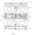
- one embodiment of the wound closure device is configured in a clam-shell type configuration, with a first opposing member (4) and a second opposing member (6) pivotally attached to each other about a pin (2) which defines a longitudinal axis of rotation.
- Each of the opposing members having an outer face and inner face and two ends.
- each opposing member approximates a bisected cylinder which has a proximal edge (5) and a distal edge (7).
- the longitudinal pivoting axis (2) is adjacent the proximal edge.
- the two bisected cylinder halves approximate a cylinder when in the closed position, where the two distal edges are proximal to each other. When the first and second members are pivoted to an open position, the two distal edges are spread apart.
- first and second opposing members (4, 6) are illustrated herein to be half-cylinder sections in the embodiment illustrated, they may be approximated by interconnected curved arms or another equivalent configuration.
- each opposing member comprises an end closure member (8) at each end.
- Each end closure member (8) is substantially perpendicular to the distal edge, and is aligned with an end closure member on the other opposing member.
- two opposing end closure members (8) abut each other, or come towards each other, in order to enclose or partially enclose the volume between the two opposing members at each end.
- the distal edges (7) may be curved so that the distance between the two distal edges (7) is reduced towards the ends when the device is in a closed position. Either configuration is intended to minimize leakage from the wound from the ends of the wound.
- the opposing members (4, 6) have needles (12) for piercing the skin on opposite sides of the wound.
- the needles have two primary functions. The first is to anchor the device into place when it is closed in place to seal a wound. If the device were to solely rely on frictional engagement with the skin, it might easily be knocked off. The second is to cause the skin and underlying tissue to bunch up between the opposing members, as is illustrated in Figure 8 .
- the needles are long enough to penetrate the dermal layer (D) and extend into the underlying tissue. This action enhances the sealing action of the device.
- the needles (12) are alternately placed along the length of the opposing members such that the needles are interleaved.
- the needles are curved such that the piercing of skin and closing of the device brings opposing edges of the wound up into the device, as is illustrated in Figure 8 .
- the needles may have a radius of curvature similar to that of the first and second members.
- each of the opposing members (4, 6) has a pressure bar (18, 20) along the distal edge (7) of the member.
- the pressure bars (18, 20) exert relatively even pressure along the length of the wound to close the wound.
- the pressure bar may comprise frictional elements to help grip the skin, such as ridges (21) which run parallel to the distal edge.
- the pressure bar (18, 20) is configured to interact with or hide the needles of the opposing member in order to prevent exposing the needles when the device is being handled in the closed position.
- the pressure bars may be lined with a resilient material (32) which envelops the needle tips, such as neoprene or another rubbery material. The resilient material may also aid in the application of pressure to the wound.
- each of the opposing members (4, 6) has a grip (10) on the outer face.
- the grips are raised concave surfaces placed near the pivot axis.
- the grips each provide a first gripping surface (40) which is substantially parallel to the longitudinal axis, which facilitates a one-handed opening motion.
- the grips provide a second gripping surface (42) to push the first and second members apart along the longitudinal axis.
- the second gripping surface (42) may be substantially perpendicular to the longitudinal axis.
- Different grip configurations may provide suitable first and second gripping surfaces.
- the grips may be optimized for such use, as is shown in Figure 9 .
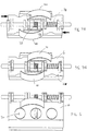
- the device is normally stored in a closed position, and is then opened by a user for use.
- various mechanisms may be used to bias the device into an open position, but allow for storage in a closed position, and also allow for locking into a closed position when the device is in storage or in use.
- the device may be biased towards its open position by a first spring (26) but is held in the closed position by cooperating ratchets (14, 16) disposed on the inner face of the first and second members.
- the ratchets (14, 16) are disengaged by moving the first member longitudinally away from the second member, as shown by the arrows in Figure 7B , allowing the device to be opened.
- a second spring (28) places longitudinal pressure on the first and second members to keep the ratchets engaged.
- a plurality of ratchet teeth on each opposing ratchet permits the user to control the closed position.
- the distal edges of the opposing members are adjacent each other, the opposing needles overlap, and all the ratchet teeth are engaged, as shown in Figure 4D .
- the device may be partially closed, such as when placed on a wound, by engaging only the end teeth of the opposing ratchets.
- the device Once the device is opened, it may be closed on the wound by forcing the two opposing members closed, against the pressure of the first spring (26), until the opposing ratchets engage each other.
- the surfaces of the two opposing members which rotationally engage each other, about the longitudinal axis bear elements which frictionally engage each other.
- one opposing member may comprise an outer cylindrical surface, while the other comprises an inner cylindrical surface.
- the two cylindrical surfaces bear against each other, and may provide sufficient friction to maintain the device in a closed position. Frictional elements such as raised ridges on the cylindrical bearing surfaces may provide additional friction.
- the device comprises a releasable engagement mechanism comprising a one-way bearing.
- the two opposing members (4, 6) rotationally engage each other about an axial pin (2) with a cylindrical bearing.
- the pin (2) is keyed at each end (3) so as to rotate with an outer cylinder (50) while being moveable in the axial direction.
- An inner cylinder (52) rotates within the outer cylinder (50).
- a one-way bearing (54) fits within and is affixed to the inner cylinder and is frictionally engages an engagement section of the pin (2) which passes through the bearing (54).
- the pin (2) comprises two telescoping sections which are biased outwards with an internal spring, and which can be overcome by pressing the two ends (3) inwards.
- the pin (2) also comprises a reduced diameter portion which is smaller than the engagement section and the inner diameter of the bearing (54).
- the engagement section of the pin engages the inner diameter of the one-way bearing, which permits the device to rotate closed, but prevents rotation in the open direction.
- the pin is compressed by squeezing the two ends (3), the pin slides laterally such that the reduced diameter portion is disposed within the one-way bearing, permitting free rotation in either direction.
- the cylinder and one-way bearing assemblies are provided at both ends of the device, which permits greater torque loads on the device in the closed position. It also permits slightly asymmetric application of the device on a wound, where the distal edges of the two opposing members are not exactly parallel. The torsional force acting on the one-way bearing at each end may be different.
- a user can with one hand and one motion close the device about a wound, and the device will remain locked in a closed position.
- the device can be unlocked to release the device to its open position by a simple movement, again permitting one-handed use, if necessary or desired.
- each of the opposing members (4, 6) may have an optional stabilizing pad (22, 24) for balancing the device about a closed wound. Because of the mass of the device, it may have a tendency to sway when in position, closed on a wound.
- the stabilizing pads (22, 24) prevent or limit that swaying motion.
- the stabilizing pads are extended along the length of the distal edge, approximately tangent to the cylinder formed by the closed members and parallel to the surface of the wound.
- each of the opposing members (4, 6) defines a number of openings (30), which allow the user to visualize the wound.
- the openings (30) may also allow access for medical or surgical instruments while the device is in use.
- the wound closure device is provided as a kit comprising a wound closure device in a sterile package, which may be opened with one hand. Therefore, it may be seen that a user may take the sterile package, open it and remove the device which is stored in its closed position, open it with one hand, place it on a wound, and close it, all with one hand and in very little time.
Landscapes
- Health & Medical Sciences (AREA)
- Life Sciences & Earth Sciences (AREA)
- Surgery (AREA)
- Molecular Biology (AREA)
- General Health & Medical Sciences (AREA)
- Biomedical Technology (AREA)
- Heart & Thoracic Surgery (AREA)
- Medical Informatics (AREA)
- Nuclear Medicine, Radiotherapy & Molecular Imaging (AREA)
- Animal Behavior & Ethology (AREA)
- Engineering & Computer Science (AREA)
- Public Health (AREA)
- Veterinary Medicine (AREA)
- Surgical Instruments (AREA)
- Clamps And Clips (AREA)
- Media Introduction/Drainage Providing Device (AREA)
- Finger-Pressure Massage (AREA)
Claims (6)
- Wundverschlussvorrichtung, umfassend:(a) ein erstes gegenüberliegendes Element (4) und ein zweites gegenüberliegendes Element (6), die um eine Längsachse (2) in Eingriff stehen, wobei jedes um die Achse zwischen einer geschlossenen Position und einer offenen Position relativ zueinander schwenkbar ist, wobei jedes der gegenüberliegenden Elemente eine proximale Kante nahe der Längsachse und eine distale Kante aufweist;(b) Hautdurchdringungsmittel (12) zur Verankerung der Vorrichtung, die jeweils an dem ersten und zweiten gegenüberliegenden Element angeordnet sind;(c) einen Druckstab (18, 20) entlang jeder distalen Kante; und(d) lösbare Verriegelungsmittel zum Vorspannen oder Halten der Vorrichtung in der geschlossenen Position;
wobei die Wundverschlussvorrichtung dadurch gekennzeichnet ist, dass die beiden gegenüberliegenden Elemente reibschlüssig ineinander greifen, um in der geschlossenen Position zu bleiben. - Vorrichtung nach Anspruch 1, wobei jedes gegenüberliegende Element ein Endverschlusselement umfasst, das im Wesentlichen senkrecht zur distalen Kante steht und auf ein gegenüberliegendes Endverschlusselement ausgerichtet ist.
- Vorrichtung nach Anspruch 1, wobei das Hautdurchdringungsmittel mehrere Nadeln umfasst, die entlang jedes Druckstabes jedes gegenüberliegenden Elements angeordnet sind.
- Vorrichtung nach Anspruch 3, wobei die Nadeln lang genug sind, um die Haut zu durchdringen und das darunter liegende Gewebe zu durchstechen.
- Vorrichtung nach Anspruch 3 oder 4, wobei die Nadeln mit einem Krümmungsradius gekrümmt sind, der im Wesentlichen dem Krümmungsradius der gegenüberliegenden Elemente entspricht.
- Vorrichtung nach Anspruch 1, wobei der Reibschluss durch mehrere Längsrippen an einer oder beiden gegenüberliegenden Elementlagerflächen der gegenüberliegenden Elemente verstärkt wird.
Applications Claiming Priority (2)
| Application Number | Priority Date | Filing Date | Title |
|---|---|---|---|
| US39456610P | 2010-10-19 | 2010-10-19 | |
| PCT/CA2011/001170 WO2012051706A1 (en) | 2010-10-19 | 2011-10-19 | Wound clamp |
Publications (3)
| Publication Number | Publication Date |
|---|---|
| EP2629680A1 EP2629680A1 (de) | 2013-08-28 |
| EP2629680A4 EP2629680A4 (de) | 2016-03-09 |
| EP2629680B1 true EP2629680B1 (de) | 2020-07-01 |
Family
ID=45974594
Family Applications (1)
| Application Number | Title | Priority Date | Filing Date |
|---|---|---|---|
| EP11833670.0A Active EP2629680B1 (de) | 2010-10-19 | 2011-10-19 | Wundklammer |
Country Status (12)
| Country | Link |
|---|---|
| US (1) | US9307990B2 (de) |
| EP (1) | EP2629680B1 (de) |
| JP (1) | JP5973448B2 (de) |
| KR (1) | KR20130140733A (de) |
| CN (1) | CN103153211B (de) |
| AU (1) | AU2011318194B2 (de) |
| BR (1) | BR112013009022A2 (de) |
| CA (1) | CA2813652C (de) |
| IL (1) | IL225570A (de) |
| NZ (2) | NZ609606A (de) |
| RU (1) | RU2620348C2 (de) |
| WO (1) | WO2012051706A1 (de) |
Families Citing this family (14)
| Publication number | Priority date | Publication date | Assignee | Title |
|---|---|---|---|---|
| US20140309687A1 (en) | 2010-10-19 | 2014-10-16 | Innovative Trauma Care Inc. | Wound clamp |
| EP2629680B1 (de) | 2010-10-19 | 2020-07-01 | Innovative Trauma Care, Inc. | Wundklammer |
| US9149265B2 (en) | 2011-02-26 | 2015-10-06 | Abbott Cardiovascular Systems, Inc. | Hinged tissue support device |
| AU2013356931A1 (en) * | 2012-12-11 | 2015-07-02 | Innovative Trauma Care, Inc. | Wound clamp |
| US9486132B2 (en) * | 2013-01-17 | 2016-11-08 | Abbott Cardiovascular Systems, Inc. | Access device for accessing tissue |
| CA2917078C (en) * | 2013-06-28 | 2022-05-17 | Bill Russell Alexander | Catheter anchoring device and method |
| PL3079601T3 (pl) * | 2013-12-11 | 2024-10-21 | Innovative Trauma Care, Inc. | Dwurzędowy mechanizm zapadkowy z funkcją pojedynczego obejścia („uzbrojenia”) |
| CN103892883A (zh) * | 2014-04-15 | 2014-07-02 | 江苏德威兰医疗器械有限公司 | 一种紧急止血夹 |
| JP6078929B2 (ja) * | 2015-03-31 | 2017-02-15 | 清三 三好 | 止血力表示クランプ |
| AU2017359336B2 (en) | 2016-11-09 | 2023-07-06 | The United States Of America, As Represented By The Secretary, Department Of Health And Human Services | Tissue clamp and implantation method |
| CN106388895A (zh) * | 2016-12-14 | 2017-02-15 | 中国人民解放军总医院 | 一种用于皮肤伤口的快速闭合装置 |
| KR102375157B1 (ko) * | 2017-05-24 | 2022-03-17 | 현대자동차주식회사 | 착용식 로봇의 결박장치 |
| CN111493958A (zh) * | 2020-04-30 | 2020-08-07 | 福建骏格科技有限公司 | 一种新型夹式皮钉组 |
| CN111493957A (zh) * | 2020-04-30 | 2020-08-07 | 福建骏格科技有限公司 | 一种夹式钉合器 |
Family Cites Families (17)
| Publication number | Priority date | Publication date | Assignee | Title |
|---|---|---|---|---|
| US456458A (en) * | 1891-07-21 | Caster | ||
| GB456458A (en) | 1935-06-04 | 1936-11-10 | Nikolaus Braun | Improvements in or relating to wound clasps |
| US2881762A (en) * | 1955-02-09 | 1959-04-14 | Robert J Lowrie | Surgical staple and stapler |
| US3068869A (en) * | 1959-10-01 | 1962-12-18 | Sheiden Charles Hunter | Tissue suture clamp |
| US4317451A (en) * | 1980-02-19 | 1982-03-02 | Ethicon, Inc. | Plastic surgical staple |
| US4505274A (en) * | 1980-10-17 | 1985-03-19 | Propper Manufacturing Co., Inc. | Suture clip |
| US4531522A (en) * | 1983-06-20 | 1985-07-30 | Ethicon, Inc. | Two-piece tissue fastener with locking top and method for applying same |
| CH668691A5 (de) * | 1985-05-31 | 1989-01-31 | Alice Dr Med Utz | Wundklammer. |
| SU1377054A1 (ru) * | 1985-11-28 | 1988-02-28 | С. А. Попов | Хирургическа скобка |
| SU1301387A1 (ru) * | 1985-12-17 | 1987-04-07 | Днепропетровский государственный университет им.300-летия воссоединения Украины с Россией | Пинцет-расширитель |
| SU1405825A1 (ru) * | 1986-08-06 | 1988-06-30 | Научно-производственное объединение "Мединструмент" | Устройство дл пережати органов |
| US5486196A (en) * | 1992-02-13 | 1996-01-23 | Medchem Products, Inc. | Apparatus for the closure of wide skin defects by stretching of skin |
| US20050251204A1 (en) | 2004-05-06 | 2005-11-10 | Jurg Attinger | Wound clamp |
| US7033377B2 (en) * | 2004-05-27 | 2006-04-25 | Mavrek Medical, L.L.C. | Surgical device for capturing, positioning and aligning portions of a severed human sternum |
| US20060167458A1 (en) * | 2005-01-25 | 2006-07-27 | Lorenz Gabele | Lock and release mechanism for a sternal clamp |
| US20090182374A1 (en) * | 2008-01-10 | 2009-07-16 | John Keith | Surgical staple |
| EP2629680B1 (de) | 2010-10-19 | 2020-07-01 | Innovative Trauma Care, Inc. | Wundklammer |
-
2011
- 2011-10-19 EP EP11833670.0A patent/EP2629680B1/de active Active
- 2011-10-19 BR BR112013009022A patent/BR112013009022A2/pt not_active IP Right Cessation
- 2011-10-19 US US13/877,897 patent/US9307990B2/en active Active
- 2011-10-19 RU RU2013122861A patent/RU2620348C2/ru not_active IP Right Cessation
- 2011-10-19 WO PCT/CA2011/001170 patent/WO2012051706A1/en not_active Ceased
- 2011-10-19 CA CA2813652A patent/CA2813652C/en active Active
- 2011-10-19 NZ NZ60960611A patent/NZ609606A/en not_active IP Right Cessation
- 2011-10-19 JP JP2013534134A patent/JP5973448B2/ja active Active
- 2011-10-19 NZ NZ706754A patent/NZ706754A/en not_active IP Right Cessation
- 2011-10-19 KR KR1020137012740A patent/KR20130140733A/ko not_active Ceased
- 2011-10-19 CN CN201180050261.9A patent/CN103153211B/zh active Active
- 2011-10-19 AU AU2011318194A patent/AU2011318194B2/en not_active Ceased
-
2013
- 2013-04-04 IL IL225570A patent/IL225570A/en active IP Right Grant
Non-Patent Citations (1)
| Title |
|---|
| None * |
Also Published As
| Publication number | Publication date |
|---|---|
| AU2011318194A1 (en) | 2013-04-11 |
| WO2012051706A1 (en) | 2012-04-26 |
| AU2011318194B2 (en) | 2015-06-11 |
| IL225570A0 (en) | 2013-06-27 |
| KR20130140733A (ko) | 2013-12-24 |
| IL225570A (en) | 2017-07-31 |
| US9307990B2 (en) | 2016-04-12 |
| NZ706754A (en) | 2016-11-25 |
| JP2013543421A (ja) | 2013-12-05 |
| CA2813652C (en) | 2019-12-03 |
| BR112013009022A2 (pt) | 2017-10-17 |
| US20130204294A1 (en) | 2013-08-08 |
| RU2013122861A (ru) | 2014-11-27 |
| EP2629680A1 (de) | 2013-08-28 |
| CA2813652A1 (en) | 2012-04-26 |
| EP2629680A4 (de) | 2016-03-09 |
| CN103153211B (zh) | 2016-12-07 |
| NZ609606A (en) | 2015-04-24 |
| CN103153211A (zh) | 2013-06-12 |
| RU2620348C2 (ru) | 2017-05-24 |
| JP5973448B2 (ja) | 2016-08-23 |
Similar Documents
| Publication | Publication Date | Title |
|---|---|---|
| EP2629680B1 (de) | Wundklammer | |
| US11096690B2 (en) | Wound clamp | |
| EP2931139B1 (de) | Wundklammer | |
| CA2933406C (en) | Double-row ratchet locking mechanism with single-bypass ('arming') functionality | |
| CN208693623U (zh) | 一种快速止血包扎装置 | |
| AU2017201066A1 (en) | Wound clamp | |
| HK1184039B (en) | Wound clamp | |
| HK1184039A (en) | Wound clamp | |
| KR200468799Y1 (ko) | 지혈 밴드의 결속 장치 | |
| WO2017216781A1 (en) | Harness for care of bleeding wounds | |
| O'Meara¹ et al. | Trauma: Extremity Injury | |
| HK1242940A1 (en) | Double-row ratchet locking mechanism with single-bypass (‘arming’) functionality |
Legal Events
| Date | Code | Title | Description |
|---|---|---|---|
| PUAI | Public reference made under article 153(3) epc to a published international application that has entered the european phase |
Free format text: ORIGINAL CODE: 0009012 |
|
| 17P | Request for examination filed |
Effective date: 20130517 |
|
| AK | Designated contracting states |
Kind code of ref document: A1 Designated state(s): AL AT BE BG CH CY CZ DE DK EE ES FI FR GB GR HR HU IE IS IT LI LT LU LV MC MK MT NL NO PL PT RO RS SE SI SK SM TR |
|
| DAX | Request for extension of the european patent (deleted) | ||
| RA4 | Supplementary search report drawn up and despatched (corrected) |
Effective date: 20160204 |
|
| RIC1 | Information provided on ipc code assigned before grant |
Ipc: A61B 17/08 20060101AFI20160129BHEP |
|
| STAA | Information on the status of an ep patent application or granted ep patent |
Free format text: STATUS: EXAMINATION IS IN PROGRESS |
|
| 17Q | First examination report despatched |
Effective date: 20181022 |
|
| GRAP | Despatch of communication of intention to grant a patent |
Free format text: ORIGINAL CODE: EPIDOSNIGR1 |
|
| STAA | Information on the status of an ep patent application or granted ep patent |
Free format text: STATUS: GRANT OF PATENT IS INTENDED |
|
| INTG | Intention to grant announced |
Effective date: 20200128 |
|
| GRAS | Grant fee paid |
Free format text: ORIGINAL CODE: EPIDOSNIGR3 |
|
| GRAA | (expected) grant |
Free format text: ORIGINAL CODE: 0009210 |
|
| STAA | Information on the status of an ep patent application or granted ep patent |
Free format text: STATUS: THE PATENT HAS BEEN GRANTED |
|
| AK | Designated contracting states |
Kind code of ref document: B1 Designated state(s): AL AT BE BG CH CY CZ DE DK EE ES FI FR GB GR HR HU IE IS IT LI LT LU LV MC MK MT NL NO PL PT RO RS SE SI SK SM TR |
|
| REG | Reference to a national code |
Ref country code: GB Ref legal event code: FG4D |
|
| REG | Reference to a national code |
Ref country code: CH Ref legal event code: EP Ref country code: AT Ref legal event code: REF Ref document number: 1285386 Country of ref document: AT Kind code of ref document: T Effective date: 20200715 |
|
| REG | Reference to a national code |
Ref country code: DE Ref legal event code: R096 Ref document number: 602011067600 Country of ref document: DE |
|
| REG | Reference to a national code |
Ref country code: IE Ref legal event code: FG4D |
|
| REG | Reference to a national code |
Ref country code: NL Ref legal event code: FP |
|
| REG | Reference to a national code |
Ref country code: LT Ref legal event code: MG4D |
|
| PG25 | Lapsed in a contracting state [announced via postgrant information from national office to epo] |
Ref country code: BG Free format text: LAPSE BECAUSE OF FAILURE TO SUBMIT A TRANSLATION OF THE DESCRIPTION OR TO PAY THE FEE WITHIN THE PRESCRIBED TIME-LIMIT Effective date: 20201001 |
|
| REG | Reference to a national code |
Ref country code: AT Ref legal event code: MK05 Ref document number: 1285386 Country of ref document: AT Kind code of ref document: T Effective date: 20200701 |
|
| PG25 | Lapsed in a contracting state [announced via postgrant information from national office to epo] |
Ref country code: HR Free format text: LAPSE BECAUSE OF FAILURE TO SUBMIT A TRANSLATION OF THE DESCRIPTION OR TO PAY THE FEE WITHIN THE PRESCRIBED TIME-LIMIT Effective date: 20200701 Ref country code: PT Free format text: LAPSE BECAUSE OF FAILURE TO SUBMIT A TRANSLATION OF THE DESCRIPTION OR TO PAY THE FEE WITHIN THE PRESCRIBED TIME-LIMIT Effective date: 20201102 Ref country code: LT Free format text: LAPSE BECAUSE OF FAILURE TO SUBMIT A TRANSLATION OF THE DESCRIPTION OR TO PAY THE FEE WITHIN THE PRESCRIBED TIME-LIMIT Effective date: 20200701 Ref country code: FI Free format text: LAPSE BECAUSE OF FAILURE TO SUBMIT A TRANSLATION OF THE DESCRIPTION OR TO PAY THE FEE WITHIN THE PRESCRIBED TIME-LIMIT Effective date: 20200701 Ref country code: GR Free format text: LAPSE BECAUSE OF FAILURE TO SUBMIT A TRANSLATION OF THE DESCRIPTION OR TO PAY THE FEE WITHIN THE PRESCRIBED TIME-LIMIT Effective date: 20201002 Ref country code: NO Free format text: LAPSE BECAUSE OF FAILURE TO SUBMIT A TRANSLATION OF THE DESCRIPTION OR TO PAY THE FEE WITHIN THE PRESCRIBED TIME-LIMIT Effective date: 20201001 Ref country code: AT Free format text: LAPSE BECAUSE OF FAILURE TO SUBMIT A TRANSLATION OF THE DESCRIPTION OR TO PAY THE FEE WITHIN THE PRESCRIBED TIME-LIMIT Effective date: 20200701 Ref country code: CZ Free format text: LAPSE BECAUSE OF FAILURE TO SUBMIT A TRANSLATION OF THE DESCRIPTION OR TO PAY THE FEE WITHIN THE PRESCRIBED TIME-LIMIT Effective date: 20200701 Ref country code: ES Free format text: LAPSE BECAUSE OF FAILURE TO SUBMIT A TRANSLATION OF THE DESCRIPTION OR TO PAY THE FEE WITHIN THE PRESCRIBED TIME-LIMIT Effective date: 20200701 Ref country code: SE Free format text: LAPSE BECAUSE OF FAILURE TO SUBMIT A TRANSLATION OF THE DESCRIPTION OR TO PAY THE FEE WITHIN THE PRESCRIBED TIME-LIMIT Effective date: 20200701 |
|
| PG25 | Lapsed in a contracting state [announced via postgrant information from national office to epo] |
Ref country code: PL Free format text: LAPSE BECAUSE OF FAILURE TO SUBMIT A TRANSLATION OF THE DESCRIPTION OR TO PAY THE FEE WITHIN THE PRESCRIBED TIME-LIMIT Effective date: 20200701 Ref country code: RS Free format text: LAPSE BECAUSE OF FAILURE TO SUBMIT A TRANSLATION OF THE DESCRIPTION OR TO PAY THE FEE WITHIN THE PRESCRIBED TIME-LIMIT Effective date: 20200701 Ref country code: LV Free format text: LAPSE BECAUSE OF FAILURE TO SUBMIT A TRANSLATION OF THE DESCRIPTION OR TO PAY THE FEE WITHIN THE PRESCRIBED TIME-LIMIT Effective date: 20200701 Ref country code: IS Free format text: LAPSE BECAUSE OF FAILURE TO SUBMIT A TRANSLATION OF THE DESCRIPTION OR TO PAY THE FEE WITHIN THE PRESCRIBED TIME-LIMIT Effective date: 20201101 |
|
| REG | Reference to a national code |
Ref country code: DE Ref legal event code: R097 Ref document number: 602011067600 Country of ref document: DE |
|
| PG25 | Lapsed in a contracting state [announced via postgrant information from national office to epo] |
Ref country code: SM Free format text: LAPSE BECAUSE OF FAILURE TO SUBMIT A TRANSLATION OF THE DESCRIPTION OR TO PAY THE FEE WITHIN THE PRESCRIBED TIME-LIMIT Effective date: 20200701 Ref country code: RO Free format text: LAPSE BECAUSE OF FAILURE TO SUBMIT A TRANSLATION OF THE DESCRIPTION OR TO PAY THE FEE WITHIN THE PRESCRIBED TIME-LIMIT Effective date: 20200701 Ref country code: IT Free format text: LAPSE BECAUSE OF FAILURE TO SUBMIT A TRANSLATION OF THE DESCRIPTION OR TO PAY THE FEE WITHIN THE PRESCRIBED TIME-LIMIT Effective date: 20200701 Ref country code: EE Free format text: LAPSE BECAUSE OF FAILURE TO SUBMIT A TRANSLATION OF THE DESCRIPTION OR TO PAY THE FEE WITHIN THE PRESCRIBED TIME-LIMIT Effective date: 20200701 Ref country code: DK Free format text: LAPSE BECAUSE OF FAILURE TO SUBMIT A TRANSLATION OF THE DESCRIPTION OR TO PAY THE FEE WITHIN THE PRESCRIBED TIME-LIMIT Effective date: 20200701 |
|
| PLBE | No opposition filed within time limit |
Free format text: ORIGINAL CODE: 0009261 |
|
| STAA | Information on the status of an ep patent application or granted ep patent |
Free format text: STATUS: NO OPPOSITION FILED WITHIN TIME LIMIT |
|
| PG25 | Lapsed in a contracting state [announced via postgrant information from national office to epo] |
Ref country code: AL Free format text: LAPSE BECAUSE OF FAILURE TO SUBMIT A TRANSLATION OF THE DESCRIPTION OR TO PAY THE FEE WITHIN THE PRESCRIBED TIME-LIMIT Effective date: 20200701 |
|
| REG | Reference to a national code |
Ref country code: CH Ref legal event code: PL |
|
| 26N | No opposition filed |
Effective date: 20210406 |
|
| PG25 | Lapsed in a contracting state [announced via postgrant information from national office to epo] |
Ref country code: SK Free format text: LAPSE BECAUSE OF FAILURE TO SUBMIT A TRANSLATION OF THE DESCRIPTION OR TO PAY THE FEE WITHIN THE PRESCRIBED TIME-LIMIT Effective date: 20200701 Ref country code: LU Free format text: LAPSE BECAUSE OF NON-PAYMENT OF DUE FEES Effective date: 20201019 Ref country code: MC Free format text: LAPSE BECAUSE OF FAILURE TO SUBMIT A TRANSLATION OF THE DESCRIPTION OR TO PAY THE FEE WITHIN THE PRESCRIBED TIME-LIMIT Effective date: 20200701 |
|
| REG | Reference to a national code |
Ref country code: BE Ref legal event code: MM Effective date: 20201031 |
|
| PG25 | Lapsed in a contracting state [announced via postgrant information from national office to epo] |
Ref country code: CH Free format text: LAPSE BECAUSE OF NON-PAYMENT OF DUE FEES Effective date: 20201031 Ref country code: BE Free format text: LAPSE BECAUSE OF NON-PAYMENT OF DUE FEES Effective date: 20201031 Ref country code: LI Free format text: LAPSE BECAUSE OF NON-PAYMENT OF DUE FEES Effective date: 20201031 Ref country code: SI Free format text: LAPSE BECAUSE OF FAILURE TO SUBMIT A TRANSLATION OF THE DESCRIPTION OR TO PAY THE FEE WITHIN THE PRESCRIBED TIME-LIMIT Effective date: 20200701 |
|
| PG25 | Lapsed in a contracting state [announced via postgrant information from national office to epo] |
Ref country code: IE Free format text: LAPSE BECAUSE OF NON-PAYMENT OF DUE FEES Effective date: 20201019 |
|
| PG25 | Lapsed in a contracting state [announced via postgrant information from national office to epo] |
Ref country code: TR Free format text: LAPSE BECAUSE OF FAILURE TO SUBMIT A TRANSLATION OF THE DESCRIPTION OR TO PAY THE FEE WITHIN THE PRESCRIBED TIME-LIMIT Effective date: 20200701 Ref country code: MT Free format text: LAPSE BECAUSE OF FAILURE TO SUBMIT A TRANSLATION OF THE DESCRIPTION OR TO PAY THE FEE WITHIN THE PRESCRIBED TIME-LIMIT Effective date: 20200701 Ref country code: CY Free format text: LAPSE BECAUSE OF FAILURE TO SUBMIT A TRANSLATION OF THE DESCRIPTION OR TO PAY THE FEE WITHIN THE PRESCRIBED TIME-LIMIT Effective date: 20200701 |
|
| PG25 | Lapsed in a contracting state [announced via postgrant information from national office to epo] |
Ref country code: MK Free format text: LAPSE BECAUSE OF FAILURE TO SUBMIT A TRANSLATION OF THE DESCRIPTION OR TO PAY THE FEE WITHIN THE PRESCRIBED TIME-LIMIT Effective date: 20200701 |
|
| P01 | Opt-out of the competence of the unified patent court (upc) registered |
Free format text: CASE NUMBER: UPC_APP_409998/2023 Effective date: 20230508 |
|
| PGFP | Annual fee paid to national office [announced via postgrant information from national office to epo] |
Ref country code: NL Payment date: 20241022 Year of fee payment: 14 |
|
| PGFP | Annual fee paid to national office [announced via postgrant information from national office to epo] |
Ref country code: DE Payment date: 20241022 Year of fee payment: 14 |
|
| PGFP | Annual fee paid to national office [announced via postgrant information from national office to epo] |
Ref country code: GB Payment date: 20241023 Year of fee payment: 14 |
|
| PGFP | Annual fee paid to national office [announced via postgrant information from national office to epo] |
Ref country code: FR Payment date: 20241022 Year of fee payment: 14 |