EP2629041A2 - Structure of a heat exchanger - Google Patents
Structure of a heat exchanger Download PDFInfo
- Publication number
- EP2629041A2 EP2629041A2 EP13401013.1A EP13401013A EP2629041A2 EP 2629041 A2 EP2629041 A2 EP 2629041A2 EP 13401013 A EP13401013 A EP 13401013A EP 2629041 A2 EP2629041 A2 EP 2629041A2
- Authority
- EP
- European Patent Office
- Prior art keywords
- heat exchanger
- branch
- fluid
- structure according
- microchannel
- Prior art date
- Legal status (The legal status is an assumption and is not a legal conclusion. Google has not performed a legal analysis and makes no representation as to the accuracy of the status listed.)
- Granted
Links
Images


Classifications
-
- F—MECHANICAL ENGINEERING; LIGHTING; HEATING; WEAPONS; BLASTING
- F28—HEAT EXCHANGE IN GENERAL
- F28F—DETAILS OF HEAT-EXCHANGE AND HEAT-TRANSFER APPARATUS, OF GENERAL APPLICATION
- F28F3/00—Plate-like or laminated elements; Assemblies of plate-like or laminated elements
- F28F3/12—Elements constructed in the shape of a hollow panel, e.g. with channels
-
- H—ELECTRICITY
- H01—ELECTRIC ELEMENTS
- H01L—SEMICONDUCTOR DEVICES NOT COVERED BY CLASS H10
- H01L23/00—Details of semiconductor or other solid state devices
- H01L23/34—Arrangements for cooling, heating, ventilating or temperature compensation ; Temperature sensing arrangements
- H01L23/42—Fillings or auxiliary members in containers or encapsulations selected or arranged to facilitate heating or cooling
- H01L23/427—Cooling by change of state, e.g. use of heat pipes
-
- F—MECHANICAL ENGINEERING; LIGHTING; HEATING; WEAPONS; BLASTING
- F28—HEAT EXCHANGE IN GENERAL
- F28D—HEAT-EXCHANGE APPARATUS, NOT PROVIDED FOR IN ANOTHER SUBCLASS, IN WHICH THE HEAT-EXCHANGE MEDIA DO NOT COME INTO DIRECT CONTACT
- F28D21/00—Heat-exchange apparatus not covered by any of the groups F28D1/00 - F28D20/00
- F28D2021/0019—Other heat exchangers for particular applications; Heat exchange systems not otherwise provided for
- F28D2021/0061—Other heat exchangers for particular applications; Heat exchange systems not otherwise provided for for phase-change applications
-
- F—MECHANICAL ENGINEERING; LIGHTING; HEATING; WEAPONS; BLASTING
- F28—HEAT EXCHANGE IN GENERAL
- F28D—HEAT-EXCHANGE APPARATUS, NOT PROVIDED FOR IN ANOTHER SUBCLASS, IN WHICH THE HEAT-EXCHANGE MEDIA DO NOT COME INTO DIRECT CONTACT
- F28D21/00—Heat-exchange apparatus not covered by any of the groups F28D1/00 - F28D20/00
- F28D2021/0019—Other heat exchangers for particular applications; Heat exchange systems not otherwise provided for
- F28D2021/0068—Other heat exchangers for particular applications; Heat exchange systems not otherwise provided for for refrigerant cycles
-
- F—MECHANICAL ENGINEERING; LIGHTING; HEATING; WEAPONS; BLASTING
- F28—HEAT EXCHANGE IN GENERAL
- F28F—DETAILS OF HEAT-EXCHANGE AND HEAT-TRANSFER APPARATUS, OF GENERAL APPLICATION
- F28F2210/00—Heat exchange conduits
- F28F2210/02—Heat exchange conduits with particular branching, e.g. fractal conduit arrangements
-
- F—MECHANICAL ENGINEERING; LIGHTING; HEATING; WEAPONS; BLASTING
- F28—HEAT EXCHANGE IN GENERAL
- F28F—DETAILS OF HEAT-EXCHANGE AND HEAT-TRANSFER APPARATUS, OF GENERAL APPLICATION
- F28F2210/00—Heat exchange conduits
- F28F2210/10—Particular layout, e.g. for uniform temperature distribution
-
- F—MECHANICAL ENGINEERING; LIGHTING; HEATING; WEAPONS; BLASTING
- F28—HEAT EXCHANGE IN GENERAL
- F28F—DETAILS OF HEAT-EXCHANGE AND HEAT-TRANSFER APPARATUS, OF GENERAL APPLICATION
- F28F2260/00—Heat exchangers or heat exchange elements having special size, e.g. microstructures
- F28F2260/02—Heat exchangers or heat exchange elements having special size, e.g. microstructures having microchannels
-
- H—ELECTRICITY
- H01—ELECTRIC ELEMENTS
- H01L—SEMICONDUCTOR DEVICES NOT COVERED BY CLASS H10
- H01L2924/00—Indexing scheme for arrangements or methods for connecting or disconnecting semiconductor or solid-state bodies as covered by H01L24/00
- H01L2924/0001—Technical content checked by a classifier
- H01L2924/0002—Not covered by any one of groups H01L24/00, H01L24/00 and H01L2224/00
Definitions
- the invention relates to a heat exchanger structure for an evaporator structure or a condenser structure, preferably as a component of a microstructured heat exchanger according to the first patent claim.
- Said heat exchanger structure is used for the fluid passage of a fluid fraction or a part thereof through a heat exchanger, preferably a fluidic micro heat exchanger in layered construction.
- a heat exchanger preferably a fluidic micro heat exchanger in layered construction.
- the fluid passage for the fluid fractions is carried out in each plane in microchannels, which interact with the other fluid fractions by heat exchange, i. E. to warm up or cool down.
- An evaporator structure is a heat exchanger structure in which liquid constituents of a fluid passed through are completely or partially vaporized. The fluid is preferably heated.
- An evaporator structure is e.g. used in refrigeration, e.g. as surface coolers in electronics applications (e.g., chip cooling), as cooling passages for micro heat exchangers (e.g., in the refrigerator), or for process applications requiring as complete a vaporization as possible.
- the media used are e.g. special refrigeration fluids, e.g. R134a for cooling systems.
- microstructured evaporation structures as exemplified in [1] or [2] , preferably have long straight channels.
- microstructures designed for liquid evaporation such as the round-robin evaporator, exemplified in [3], wherein during evaporation the mixing of liquid and vapor fluid and thus the temperature distribution is improved.
- the residence time of the medium in the component which is about 1000 times shorter due to the increased volume flow reduces the transferable (and for the evaporation required) amount of heat. The volume increase thereby limits the previous micro-evaporator.
- a condenser structure is a heat exchanger structure in which gaseous or vaporous components of a fluid passing through it are condensed in whole or in part, i. be liquefied.
- the fluid is preferably cooled.
- the object of the invention is to propose a heat exchanger structure of the type mentioned above, however, with increased efficiency.
- Another object of the invention is to propose a condenser structure and an evaporator structure with increased efficiency.
- the starting point is a heat exchanger with a heat exchanger structure and a method for operating this heat exchanger structure.
- this channel are provided as passages for a fluid flow.
- the fluid is tempered when passing through these channels and thereby passes completely or partially through a phase boundary of liquid to gas or vapor or vice versa.
- a basic idea is to divert the fluid fraction from the fluid flow at at least one location per channel in the heat exchanger, which has already completed the aforementioned phase transformation by means of the temperature control.
- the branched-off part of the fluid flow is conducted separately by a corresponding method, preferably directly from the heat exchanger structure, while the remaining part of the fluid flow remains in the channels and is further heated. Consequently, the heat exchanger structure has means for branching off the part of the fluid flow which has already undergone a phase transformation by the temperature control (target phase).
- the heat exchanger structure is used for liquefaction or vaporization of a vapor or liquid starting fluid or fluid mixture.
- One goal is to set the target phases, i. the fluid fractions, which are already undergoing a phase change, keep away from the further heat exchange and provide the heat exchange surfaces as exclusively as possible for the phase transformation of the still to be converted phases available.
- the solution of the problem is therefore based on a modification of the heat exchanger structure described above with the aforementioned means to the effect that in the microchannels at least one location per microchannel, a branching of the aforementioned target phases takes place in a separate branch channel.
- the branch channels are used for direct discharges of the target phases from the heat exchanger, while the not yet phase-converted portions of the fluid flow remain in the microchannels in the heat exchanger.
- the fluid phases still to be converted, ie the liquid constituents in an evaporator structure and the gaseous constituents of the fluid in a condenser structure then preferably remain exclusively ie without the already converted shares in the microchannels and thus in the influence of heat transfer.
- the branched-off phase constituents no longer influence the heat transfer and the residence times of the unconverted fluid phases in the microchannels in the aforementioned manner.
- the branches are distributed over the entire channel lengths (preferably at equal distances from one another), so that a material separation takes place at several points and a phase homogeneity in the entire channel lengths is sought.
- the separation is carried out continuously.
- the already converted fluid phases are used as target phases, i. in the case of an evaporator structure, the gaseous and, in the case of a condenser structure, the liquid fluid components are preferably removed from the fluid flow already shortly after their formation and not after a complete passage through the branches.
- the separation is continuous or quasi-continuous, i. it takes place at a plurality of branches arranged one behind the other at the microchannels.
- a two-phase fluid flow which is divided by the means mentioned into a gaseous or vaporous and a liquid phase partial flow, is formed during tempering.
- the division of the phases is preferably carried out via a passage of the fluid flow through arcuate channel curvatures (arcuate fluid guidance).
- arcuate fluid guidance The material phase separation of vapor or gaseous to liquid phase takes place in the flow deflection due to the centrifugally acting in the arcuate fluid guide different levels of the lighter gaseous or vaporous and the heavier liquid phases centrifugal forces.
- the discharges are in or preferably immediately after an arcuate channel curvature on the inside, ie arranged on the inner wall of the channel curvature or on the outside, ie on the outer wall of the channel curvature.
- the discharges branch out tangentially in the flow direction from the microchannels. This reduces possible back pressure.
- a separation of liquid and gaseous fluid phases also takes place within the microstructure via the centrifugal forces produced in channel curvatures (curved fluid guidance).
- the condensed, i. the liquid after phase transition portion of the fluid via at least one fluidic branch preferably on the outside, i. at the outer wall of the channel curvature at or behind the arcuate fluid guide prematurely diverted from the microchannels of the microstructure.
- the vaporous fluid fraction remaining in the microchannels undergoes an increased residence time within the microstructure.
- the reduced proportion of condensed and liquid components is preferably removed by the discharges preferably at regular intervals to each other, so that an occupancy in particular serving as the condensation surfaces walls of the microchannels is reduced with condensed fluid fractions.
- the heat exchange takes place due to lack of liquid portions particularly advantageously directly on the walls, i. in the near-wall areas with the vaporous fluid fractions in the microchannels instead, which together with the increased residence time causes an improvement in the efficiency of the liquefaction structure.
- the regions of liquid (heavy) and vaporized medium (light) are separated gravimetrically due to the different densities (for example for water) and hence different masses m by about a factor of 1000.
- All embodiments shown in the figures show design proposals for a channel layout for areal heat exchanger structures.
- the flow direction 1 for the fluid flow is from top to bottom.
- the illustrated structures are planar channel structures, are preferably incorporated in plates or films and integrated in a micro-heat exchanger of stacked plates or films of the known basic design.
- FIG. 1a to g show simple embodiments of the heat exchanger structures by way of example on a plate or film plane 4 with a continuous microchannel 3 with inlet 2 and outlet 5 in particular for unconverted fluid fractions.
- the expansion of the film plane 4 basically limits the heat transfer path 9 of the microchannel 3.
- the heat transfer path extends to the last seen in the flow direction branch of the microchannel.
- All embodiments also show two arcuate fluid guides 7 each having a fluidic branch 8 to an outlet channel 10 for converted, ie evaporated or liquefied fluid fractions.
- 1a to d show evaporator structures as a heat exchanger structure, which are characterized in that the branch 8 is arranged on the inside of the arcuate fluid guide 7 , depending on the evaporation and flow kinematics of ( 1a ) or behind the arcuate fluid guide ( 1b shows ). Is a flow through the entire curved fluid guide required for a gravimetric separation of the liquid and gaseous fluid fractions, the branch takes place after the entire arcuate fluid guide ( 1a ). On the other hand, a transition from an arcuate fluid guide into an immediately following counter-oriented arcuate fluid guide without branching favors a material separation in the subsequent fluid guide section (cf. 1b shows ).
- branches on an arcuate fluid guide ( Figure 1C ) or the branch extends continuously over an arc segment, wherein the arcuate fluid guide on the inside is preferably delimited by a gas-permeable membrane 11, alternatively a gas-permeable, preferably open-pore body such as a filter element ( Fig.1d ).
- the branches are preferably designed as wall openings for a preferred vacuum extraction via the outlet channels. Preferably, the wall openings open out tangentially in the flow direction from the fluid guides.
- the outlet channels 10 preferably have a larger flow cross-section than the microchannel 3, in which predominantly incompressible fluid fractions flow.
- the outlet channels are optionally used as a superheater, which is assumed to be sufficient thermal insulation alone through the plate or sheet material (eg stainless chromium-nickel steel) without additional heat barriers (eg cavities).
- the corresponding process for evaporation is characterized in that liquid fluids are heated and at least partially evaporated in the microchannel, wherein the vaporized, ie vaporous fluid fractions are preferably sucked off or discharged via the branches immediately after their formation.
- 1E to g show, however, liquefaction structures as a heat exchanger structure, which are characterized in that the branch 8 is arranged on the outer side of the arcuate fluid guide 7 , depending on the condensation and flow kinematics ( 1E ) or behind the arcuate fluid guide ( Fig.1f ), in continuous condensation, in particular in the region of the curved fluid guide, alternatively at several points ( Fig.1g ).
- the branches are designed as wall openings, which open out preferably at the wall openings tangentially in the flow direction from the fluid guides.
- the outlet channels 10 preferably have a smaller flow cross-section than the microchannel 3, in which predominantly the non-condensed or not yet condensed and thus compressible fluid fractions flow.
- the outlet channels are optionally also used as a subcooler to reduce a possibly with branched off steam fraction by post-condensation, starting from a sufficient thermal insulation alone through the plate or sheet material (eg stainless chromium-nickel steel) without additional heat barriers (eg cavities) becomes.
- FIGS. 2a and b each show schematic representations of an exemplary microchannel arrangement on a schematically illustrated plate or film plane 4 of a not shown micro heat exchanger in layered construction, with which the separation of liquid and vapor phase is realized for a micro-evaporator.
- They comprise feeds 2 for a fluid to be evaporated, which are subdivided into two microchannels 3 .
- the microchannels pass through the entire film plane 4 to the outlet 5 and, in addition to an optional inlet section 6, comprise a plurality of arcuate fluid guides 7 each with a fluidic branch 8 on the respective inner side of a part of the arcuate fluid guide.
- the branches in turn lead into outlet channel strands 12 , which serve as a discharge line have an expanded cross section for gaseous or vaporous fluids.
- outlet channel strands 12 as the outlet channels in 1a to d design and use as a superheater.
- the illustrated embodiments differ in the number of branch points in the otherwise identical design of the microchannels 3 and inlet sections 6.
- 2b shows a double number of arcuate fluid guides 7 , each with a fluidic branch 8 as 2a ,
- At least one branch-free arcuate fluid guide 13 (without branching) is provided in which takes place as in the inlet section 6, a gravimetric rearrangement (preselection) of the liquid and vapor fluid components in the fluid stream.
- the subsequent rectilinear microchannel section 14 serves to homogenize the preselected phases as well as the flow.
- 2a shows opposite 2b a reduced number of arcuate fluid guides 7 , each with a fluidic branch 8, ie between two branches additionally a cascade of two directly successive arcuate fluid guides in opposite orientation without branching.
- This cascade causes an additional preselection as an intermediate inlet path in the microchannels. This additional pre-separation and design is particularly advantageous in the separation of two-phase fluid streams with low density differences.
- a liquid fluid enters the evaporator structures of the micro-evaporator.
- the film plane 4 is preferably made of a gas-tight, corrosion-resistant and sufficiently thermally conductive material (such as stainless steel, copper, etc.).
- the heat is supplied by external heat sources such as by adjacent film levels in the evaporator structure (eg fluidly via a Temper michsfluid in adjacent film levels, or by a hot surface such as electronics to be cooled).
- the fluid first flows into the inlet section 6, ie through the aforementioned mutually curved fluid guides and begins to evaporate already here.
- the direction of action of the centrifugal force changes after each curve. Steam and liquid change sides after each turn.
- the first separation of vaporous and liquid fluid fractions occurs. Due to the strong volume increase during evaporation, it is assumed that more than 50% of the channel cross section of the microchannel 3 is already filled with steam. A portion of the steam accumulates on the inside of the curved fluid guide and is there taken up by the branch 8 . The liquid portion is forced outward by the centrifugal force and remains in the microchannel. The separated vapor go is brought together through the outlet channel strands 12 and transported in this from the evaporator structure.
- the outlet channel strands 12 a preferably at least twice as high value, for example, from 0.2 to 10 mm 2 on.
- Figure 3 shows a corresponding scheme for a microfluidizer / capacitor on a film plane 4.
- the initial inlet sections 6 follow the microchannels 3 , each with an outlet 5.
- the inlet sections 6 comprise at least two consecutive channel curvatures with opposite curvature orientation.
- the analogy to the execution in 2a designed microchannels 3 have arcuate fluid guides 7 with branches 8 and outlet channel strands 12 and branch-free arcuate fluid guide 13 with subsequent rectilinear microchannel sections 14 .
- the branches for the derivation of liquid fluid components are arranged on the outside of the arcuate fluid guides 7 .
- outflow channel strands 12 are designed in their cross sections for liquid and the microchannels 3 for vapor or gaseous fluid fractions. Consequently, in contrast to 2a and b the flow cross-sections of the microchannels preferably according to the outlet channel strands.
- Figure 3 the flow cross-sections of the microchannels preferably according to the outlet channel strands.
- gas or steam enters the microchannels in a liquefaction structure.
- the heat dissipation is carried out by external heat sinks such as by adjacent film levels, eg fluidly via a Temper michsfluid in adjacent film levels, or by a cold surface such as air cooling with cooling fins.
- the gaseous or vaporous fluid to be condensed initially flows through mutually curved paths of the inlet section 6 and already begins to condense here. This results in a first material separation of liquid and gaseous or vaporous fluid fractions in the fluid stream.
- the separated liquid portion is collected in discharge channel strands 12 and transported therein from the liquefaction structure.
- the outflow channel strands 12 can be designed as a subcooler in a Mikrover Stahlssiger and deploy.
- the separation of liquid fluid fractions repeats itself iteratively in a plurality of successively arranged arcuate fluid guides 7 with fluidic branches 8.
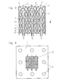
- Figure 4 shows by way of example a layout of a film of a stainless chromium-nickel steel with a planar micro-evaporator structure on a film side for use in a heat exchanger in a layered construction.
- the exemplary lateral dimensions are 120 ⁇ 120 mm for the film and 65 ⁇ 65 mm for the structure, which is worked out of the film at a later time and integrated in the micro-heat exchanger.
- the film thickness is by way of example 0.5 mm.
- the channel structures 15 are introduced by known microstructuring methods such as micro-milling, erosion or chemical etching.
- the film by way of example means for centering such as guide holes 16 .
- the channel depth is preferably uniform and in the example is between 0.1 and 0.4, preferably between 0.2 and 0.3 mm.
- the structure applies with this preferred but not necessarily required uniform depth also in terms of manufacturing technology as a 2D structure (2D corresponds to a uniform channel depth).
- the design of the micro-evaporator structure shown corresponds to that in FIG 2a reproduced.
- the channel widths of the inlet section, the microchannels and the branches are preferably between 0.1 and 1.5 mm, in the example 1 mm, that of the outlet channel strand preferably 1.5 to 4 times this aforementioned value, in the example 2 mm.
- a further embodiment of the evaporator structure provides for a step structure, preferably a step, preferably to be provided immediately after the branch. This stage is used in particular for deceleration and deflection of gas components such as gas bubbles over or into the branch. More preferably, the step comprises a baffle for gas bubbles, which projects into the flow and at which the gas bubbles impinge, braked and finally discharged into the branch.
Abstract
Description
Die Erfindung betrifft eine Wärmetauscherstruktur für eine Verdampferstruktur oder eine Verflüssigerstruktur, vorzugsweise als Komponente eines mikrostrukturierten Wärmeübertrager gemäß des ersten Patentanspruchs.The invention relates to a heat exchanger structure for an evaporator structure or a condenser structure, preferably as a component of a microstructured heat exchanger according to the first patent claim.
Die genannte Wärmetauscherstruktur dient der Fluiddurchführung einer Fluidfraktion oder eines Teils derselben durch einen Wärmetauscher, vorzugsweise einen fluidischen Mikrowärmetauschers in Schichtbauweise. In dem genannten Wärmetauscher erfolgt die Fluiddurchführung für die Fluidfraktionen jeweils ebenenweise in Mikrokanälen, wobei mit den jeweils anderen Fluidfraktionen durch Wärmeaustausch in Wechselwirkung stehen, d.h. sich erwärmen oder abkühlen.Said heat exchanger structure is used for the fluid passage of a fluid fraction or a part thereof through a heat exchanger, preferably a fluidic micro heat exchanger in layered construction. In the said heat exchanger, the fluid passage for the fluid fractions is carried out in each plane in microchannels, which interact with the other fluid fractions by heat exchange, i. E. to warm up or cool down.
Eine Verdampferstruktur ist eine Wärmetauscherstruktur, in der flüssige Bestandteile eines hindurchgeleiteten Fluids ganz oder teilweise verdampft werden. Das Fluid wird dabei vorzugsweise erwärmt.An evaporator structure is a heat exchanger structure in which liquid constituents of a fluid passed through are completely or partially vaporized. The fluid is preferably heated.
Eine Verdampferstruktur wird z.B. in der Kältetechnik eingesetzt, z.B. als Oberflächenkühler bei Elektronikanwendungen (z.B. Chipkühlung), als Kühlpassage für Mikrowärmeübertrager (z.B. im Kühlschrank) oder für verfahrenstechnische Anwendungen, die möglichst vollständige Verdampfung erfordern. Als Medien dienen z.B. spezielle Kältefluide wie z.B. R134a für Kühlanlagen.An evaporator structure is e.g. used in refrigeration, e.g. as surface coolers in electronics applications (e.g., chip cooling), as cooling passages for micro heat exchangers (e.g., in the refrigerator), or for process applications requiring as complete a vaporization as possible. The media used are e.g. special refrigeration fluids, e.g. R134a for cooling systems.
Bekannte mikrostrukturierte Verdampfungsstrukturen, wie beispielhaft in [1] oder [2] genannt, weisen bevorzugt lange gerade Kanälen auf. Es gibt zudem aber auch für Flüssigkeitsverdampfung entwickelte Mikrostrukturen wie den Rondenverdampfer, beispielhaft offenbart in [3], wobei während der Verdampfung die Durchmischung von flüssigen und dampfförmigen Fluid und damit die Temperaturverteilung verbessert wird.Known microstructured evaporation structures, as exemplified in [1] or [2] , preferably have long straight channels. However, there are also microstructures designed for liquid evaporation, such as the round-robin evaporator, exemplified in [3], wherein during evaporation the mixing of liquid and vapor fluid and thus the temperature distribution is improved.
Mikrostrukturierte Verdampferstrukturen sind in ihrer Effizienz eingeschränkt, da mit zunehmendem Dampfanteil des verdampfenden Fluids innerhalb des Verdampferstruktur die Restverdampfung des Dampf-Flüssigkeitsgemisch durch den zunehmenden Dampfanteil aus folgenden Gründen erschwert wird:
- der Anteil des noch verdampfbaren Kühlmediums nimmt kontinuierlich ab. Aufgrund der extremen Volumenzunahme beim Phasenübergang sinkt der volumenbezogene Anteil noch verdampfbaren flüssigen Kühlmediums besonders stark.
- die Wärmeleitfähigkeit der Dampfphase, die sich bevorzugt an den Wandungen der Mikrokanäle bildet, ist signifikant schlechter als die der flüssigen Phase. Dampf wirkt damit als Wärmedämmung und behindert eine weitere Verdampfung.
- Aufgrund der starken Volumenzunahme des Dampfes bei gleichzeitig konstant geringem inneren Volumen eines mikrostrukturierten Verdampfers kommt es bei einer Verdampfung zu einem starken Anstieg der Fließgeschwindigkeit im verdampfenden Fluidgemisch. Dies reduziert die Verweilzeit des noch flüssigen Mediums in der Verdampferstruktur und damit die Verdampfungseffizienz signifikant.
- mit Ansteigen der Fließgeschwindigkeit steigen auch die reibungsbedingten Druckverluste in den Mikrostrukturen, was sich auf die druckabhängige Verdampfungsenthalpie/ Verdampfungstemperatur auswirkt.
- the proportion of the still evaporable cooling medium decreases continuously. Due to the extreme increase in volume during the phase transition, the volume-related proportion of still evaporable liquid cooling medium drops particularly strongly.
- the thermal conductivity of the vapor phase, which preferably forms on the walls of the microchannels, is significantly worse than that of the liquid phase. Steam thus acts as thermal insulation and hinders further evaporation.
- Due to the large increase in volume of the vapor while maintaining a constant low internal volume of a microstructured evaporator, an evaporation leads to a sharp increase in the flow rate in the evaporating fluid mixture. This significantly reduces the residence time of the still liquid medium in the evaporator structure and thus the evaporation efficiency.
- as the flow rate increases, so does the frictional pressure losses in the microstructures, which affects the pressure-dependent enthalpy of vaporization / evaporation temperature.
Die extreme Volumenzunahme bei Verdampfung ist insbesondere für Mikrostrukturen aufgrund derer kleinen inneren Volumen ein entscheidender Nachteil beim Betrieb von Verdampfungsstrukturen. Eine etwa 1000fache Volumenzunahme bei einer Verdampfung relativiert zahlreiche Vorteile von Mikrowärmetauscherstrukturen wie z.B. die hohe Leistungsübertragungsdichte aufgrund der großen spezifischen Verdampferflächen und der kurzen Wärmeübertagungswege oder auch die kompakte Bauform, die mikrofluidische Strukturen für den Wärmetransport für einphasige Flüssigkeiten auszeichnen. Die aufgrund des erhöhten Volumenflusses etwa 1000fach kürzere Verweilzeit des Mediums im Bauteil reduziert die übertragbare (und zur Verdampfung erforderliche) Wärmemenge. Die Volumenzunahme limitiert dadurch die bisherigen Mikroverdampfer.The extreme volumetric increase in evaporation, especially for microstructures due to their small internal volumes, is a major disadvantage in the operation of vaporization structures. An approximately 1000-fold volume increase in evaporation relativises numerous advantages of micro-heat exchanger structures such as the high power transmission density due to the large specific evaporator surfaces and the short heat transfer paths or the compact design, the microfluidic structures for the heat transfer for single-phase liquids. The residence time of the medium in the component which is about 1000 times shorter due to the increased volume flow reduces the transferable (and for the evaporation required) amount of heat. The volume increase thereby limits the previous micro-evaporator.
Um eine möglichst vollständige Verdampfung des Fluids in der Verdampferstruktur zu ermöglichen, sind daher bisher entweder besonders große und damit mit größeren Herstellungskosten verbundene Verdampfungsstrukturen erforderlich oder stark reduzierte Volumenflüsse des zu verdampfenden (Kühl-) Mediums bei gleichzeitig verringerter Kühlleistung.In order to allow the most complete evaporation of the fluid in the evaporator structure, so far either either very large and therefore associated with higher production costs evaporation structures are required or greatly reduced volume flows of the (cooling) medium to be evaporated while reduced cooling capacity.
Eine Verflüssigerstruktur ist eine Wärmetauscherstruktur, in der gas- oder dampfförmige Bestandteile eines hindurchgeleiteten Fluids ganz oder teilweise kondensiert, d.h. verflüssigt werden. Das Fluid wird dabei vorzugsweise abgekühlt.A condenser structure is a heat exchanger structure in which gaseous or vaporous components of a fluid passing through it are condensed in whole or in part, i. be liquefied. The fluid is preferably cooled.
Auch für eine Verflüssigerstruktur behindern ein zunehmendes Zweiphasengemisch eine effiziente Kondensation in den Mikrokanälen. Die Wärmeübertragung erfolgt auch hier bevorzugt über die Wandungen der Mikrokanäle. Um eine möglichst vollständige Kondensation des Dampfes in der Verflüssigerstruktur zu ermöglichen, sind auch hier bisher entweder besonders große und damit mit größeren Herstellungskosten verbundene Verflüssigerstrukturen erforderlich oder stark reduzierte Volumenflüsse des Kühlmediums bei gleichzeitig verringerter Kondensationsleistung.Also for a condenser structure, an increasing two-phase mixture impedes efficient condensation in the microchannels. The heat transfer is also here preferably via the walls of the microchannels. In order to allow the most complete condensation of the vapor in the condenser structure, here too, either condenser structures which are particularly large and thus associated with greater production costs are required or greatly reduced volume flows of the cooling medium with simultaneously reduced condensation capacity.
Davon ausgehend liegt die Aufgabe der Erfindung darin, eine Wärmetauscherstruktur der eingangs genannten Art jedoch mit erhöhter Effizienz vorzuschlagen.Based on this, the object of the invention is to propose a heat exchanger structure of the type mentioned above, however, with increased efficiency.
Eine weitere Aufgabe der Erfindung liegt darin eine Verflüssigerstruktur und eine Verdampferstruktur mit erhöhter Effizienz vorzuschlagen.Another object of the invention is to propose a condenser structure and an evaporator structure with increased efficiency.
Die Aufgabe wird durch einer Wärmetauscherstruktur mit den Merkmalen des Anspruchs 1, einer Verflüssigungsstruktur mit den Merkmalen des Anspruchs 6 sowie einer Verdampfungsstruktur mit den Merkmalen des Anspruch 8 gelöst. Die auf diese rückbezogenen Unteransprüche geben vorteilhafte Ausgestaltungen wieder.The object is achieved by a heat exchanger structure having the features of
Ausgangspunkt ist ein Wärmetauscher mit Wärmetauscherstruktur sowie ein Verfahren zum Betreiben dieser Wärmetauscherstruktur. In dieser sind Kanäle als Passagen für einen Fluidstrom vorgesehen. Das Fluid wird beim Durchtritt durch diese Kanäle temperiert und durchläuft dabei vollständig oder teilweise eine Phasengrenze von flüssig zu gas- bzw. dampfförmig oder umgekehrt.The starting point is a heat exchanger with a heat exchanger structure and a method for operating this heat exchanger structure. In this channel are provided as passages for a fluid flow. The fluid is tempered when passing through these channels and thereby passes completely or partially through a phase boundary of liquid to gas or vapor or vice versa.
Eine Grundidee besteht darin, an mindestens einer Stelle je Kanal im Wärmetauscher den Fluidanteil aus dem Fluidstrom abzuzweigen, der durch die Temperierung die vorgenannte Phasenumwandlung bereits vollzogen hat. Der abgezweigte Teil des Fluidstroms wird durch ein entsprechendes Verfahren separat vorzugsweise auf direktem Weg aus der Wärmetauscherstruktur geleitet, während der restliche Teil des Fluidstroms in den Kanälen verbleibt und weiter temperiert wird. Folglich weist die Wärmetauscherstruktur Mittel zur Abzweigung des Teils des Fluidstroms auf, der durch die Temperierung die eine Phasenumwandlung bereits vollzogen hat (Zielphase).A basic idea is to divert the fluid fraction from the fluid flow at at least one location per channel in the heat exchanger, which has already completed the aforementioned phase transformation by means of the temperature control. The branched-off part of the fluid flow is conducted separately by a corresponding method, preferably directly from the heat exchanger structure, while the remaining part of the fluid flow remains in the channels and is further heated. Consequently, the heat exchanger structure has means for branching off the part of the fluid flow which has already undergone a phase transformation by the temperature control (target phase).
Die Wärmetauscherstruktur wird je nach Auslegung für eine Verflüssigung oder Verdampfung eines dampfförmigen bzw. flüssigen Ausgangsfluides oder Fluidgemisches verwendet.Depending on the design, the heat exchanger structure is used for liquefaction or vaporization of a vapor or liquid starting fluid or fluid mixture.
Eine weitere Verwendung zur Trennung eines Fluidgemisches aus zwei nicht miteinander lösbaren, aber in gleichem Aggregatzustand vorliegenden Fluiden ist mit der Wärmetauscherstruktur auch ohne einem Wärmeaustausch realisierbar. Sie ist aber durch die Erfindung mit abgedeckt.Another use for the separation of a fluid mixture of two non-dissolvable, but present in the same state of aggregation fluids can be realized with the heat exchanger structure without a heat exchange. But it is covered by the invention.
Eine Durchmischung der flüssigen und gasförmigen Phasen in den Mikrokanälen würde zwar einen Wärmeaustausch durch Wärmeanbindung der Phasen an die Wandungen als Wärmeaustauschflächen begünstigen und damit die Effizienz der Wärmeübertragung steigern, stört aber eine phasenreine Abtrennung der bereits umgewandelten Phase. Es wird folglich vorzugsweise eine Vermeidung einer Vermischung angestrebt. Ein Ziel liegt darin, die Zielphasen, d.h. die Fluidanteile, die bereits eine Phasenänderung durchlaufen sind, von dem weiteren Wärmeaustausch fernzuhalten und die Wärmeaustauschflächen möglichst ausschließlich für die Phasenumwandlung der noch umzuwandelnden Phasen zur Verfügung zu stellen.Although a mixing of the liquid and gaseous phases in the microchannels would promote heat exchange by heat bonding of the phases to the walls as heat exchange surfaces and thus increase the efficiency of heat transfer, but disturbs a phase-pure separation of the already converted phase. It is therefore desirable to avoid mixing. One goal is to set the target phases, i. the fluid fractions, which are already undergoing a phase change, keep away from the further heat exchange and provide the heat exchange surfaces as exclusively as possible for the phase transformation of the still to be converted phases available.
Die Lösung der Aufgabe basiert folglich auf einer Modifikation der eingangs beschriebenen Wärmetauscherstruktur mit den vorgenannten Mitteln dahingehend, dass in den Mikrokanälen an mindestens einer Stelle pro Mikrokanal eine Abzweigung der vorgenannten Zielphasen in einen separaten Abzweigungskanal erfolgt. Die Abzweigungskanäle dienen der direkten Ausleitungen der Zielphasen aus den Wärmetauscher, während die noch nicht phasenumgewandelten Anteile des Fluidstroms in den Mikrokanälen im Wärmetauscher verbleiben. Die noch umzuwandelnden Fluidphasen, d.h. bei einer Verdampferstruktur die flüssigen und bei einer Verflüssigerstruktur die gasförmigen Fluidbestandteile verbleiben dann vorzugsweise ausschließlich, d.h. ohne die bereits umgewandelten Anteile in den Mikrokanälen und damit im Einflussbereich der Wärmeübertragung. Die abgezweigten Phasenbestandteile beeinflussen insbesondere nicht mehr in eingangs genannter Weise die Wärmeübertragung und die Verweilzeiten der nicht umgewandelten Fluidphasen in den Mikrokanälen.The solution of the problem is therefore based on a modification of the heat exchanger structure described above with the aforementioned means to the effect that in the microchannels at least one location per microchannel, a branching of the aforementioned target phases takes place in a separate branch channel. The branch channels are used for direct discharges of the target phases from the heat exchanger, while the not yet phase-converted portions of the fluid flow remain in the microchannels in the heat exchanger. The fluid phases still to be converted, ie the liquid constituents in an evaporator structure and the gaseous constituents of the fluid in a condenser structure then preferably remain exclusively ie without the already converted shares in the microchannels and thus in the influence of heat transfer. In particular, the branched-off phase constituents no longer influence the heat transfer and the residence times of the unconverted fluid phases in the microchannels in the aforementioned manner.
Vorzugsweise sind die Abzweigungen über die gesamte Kanallängen verteilt (bevorzugt in gleichen Abständen zueinander) angeordnet, sodass an mehreren Stellen eine stoffliche Abtrennung erfolgt und eine Phasenhomogenität in den gesamten Kanallängen angestrebt wird. Die Abtrennung erfolgt dabei laufend. Die jeweils schon umgewandelten Fluidphasen werden als Zielphasen, d.h. bei einer Verdampferstruktur die gasförmigen und bei einer Verflüssigerstruktur die flüssigen Fluidbestandteile vorzugsweise bereits kurz nach der Entstehung und nicht nach einem vollständigen Durchlauf durch die Abzweigungen aus dem Fluidstrom entfernt. Weiter bevorzugt ist die Abtrennung kontinuierlich oder quasikontinuierlich, d.h. sie erfolgt an einer Vielzahl von hintereinander an den Mikrokanälen angeordneten Abzweigungen.Preferably, the branches are distributed over the entire channel lengths (preferably at equal distances from one another), so that a material separation takes place at several points and a phase homogeneity in the entire channel lengths is sought. The separation is carried out continuously. The already converted fluid phases are used as target phases, i. in the case of an evaporator structure, the gaseous and, in the case of a condenser structure, the liquid fluid components are preferably removed from the fluid flow already shortly after their formation and not after a complete passage through the branches. More preferably, the separation is continuous or quasi-continuous, i. it takes place at a plurality of branches arranged one behind the other at the microchannels.
In der Wärmetauscherstruktur entsteht bei Temperierung ein zweiphasiger Fluidstrom, der durch die genannten Mittel in einen gas- bzw. dampfförmigen und einen flüssigen Phasenteilstrom aufgeteilt wird. Die Aufteilung der Phasen erfolgt vorzugsweise über eine Durchleitung des Fluidstroms durch bogenförmige Kanalkrümmungen (bogenförmige Fluidführung). Die stoffliche Phasentrennung von dampf- bzw. gasförmiger zu flüssiger Phase erfolgt in der Strömungsumlenkung aufgrund der in der bogenförmigen Fluidführung unterschiedlich hoch auf die leichteren gas- oder dampfförmigen und die schwereren flüssigen Phasen einwirkenden Zentrifugalkräfte. Entsprechend der gewünschten Zielphase werden die Ableitungen in oder bevorzugt unmittelbar nach einer bogenförmigen Kanalkrümmung an der Innenseite, d.h. an der innen liegenden Wandung der Kanalkrümmung oder an der Außenseite, d.h. an der außen liegenden Wandung der Kanalkrümmung angeordnet.In the heat exchanger structure, a two-phase fluid flow, which is divided by the means mentioned into a gaseous or vaporous and a liquid phase partial flow, is formed during tempering. The division of the phases is preferably carried out via a passage of the fluid flow through arcuate channel curvatures (arcuate fluid guidance). The material phase separation of vapor or gaseous to liquid phase takes place in the flow deflection due to the centrifugally acting in the arcuate fluid guide different levels of the lighter gaseous or vaporous and the heavier liquid phases centrifugal forces. In accordance with the desired target phase, the discharges are in or preferably immediately after an arcuate channel curvature on the inside, ie arranged on the inner wall of the channel curvature or on the outside, ie on the outer wall of the channel curvature.
In einer bevorzugten Ausführung zweigen die Ableitungen tangential in Strömungsrichtung aus den Mikrokanälen aus. Damit werden mögliche Staudrücke reduziert.In a preferred embodiment, the discharges branch out tangentially in the flow direction from the microchannels. This reduces possible back pressure.
Bei einer Verdampferstruktur wird der dampfförmige, d.h. der nach Phasenübergang gasförmige Anteil des Fluids über mindestens eine fluidische Abzweigung vorzugsweise an der Innenseite, d.h. an der innen liegenden Wandung der Kanalkrümmung an oder hinter der bogenförmigen Fluidführung vorzeitig aus den Mikrokanälen der Mikrostruktur abgezweigt. Der abgezweigte Anteil kann dann optional z.B. in Sammelkanälen (z.B. Austrittskanalstrang) zusammengeführt und in diesen oder in einzelnen Austrittskanälen auch weiter überhitzt werden (z.B. Nassdampf zu Trockendampf). Die Sammelkanäle bzw. Austtrittskanalstränge dienen als Überhitzer. Der in den Mikrokanälen verbleibende flüssige Fluidanteil erfährt eine erhöhte Verweilzeit innerhalb der Mikrostruktur. Dies ermöglicht eine verbesserte Verdampfung aus folgenden Gründen:
- der Anteil noch verdampfbaren Mediums in den Mikrokanälen bleibt hoch, der Wärmeaustausch konzentriert sich auf den Fluidstromanteil, der den Phasenübergang noch nicht überwunden hat.
- die Verweilzeit des noch nicht verdampften Fluids in den Mikrokanälen erhöht sich, da durch eine laufende Abtrennung der sich bildenden Zielphasen einer signifikanten Volumenflusszunahme durch Verdampfung entgegengewirkt wird.
- es ergeben sich zusätzliche Verbesserungen des Wärmetransports der zur Verdampfung erforderlichen Wärmemenge, da die Wärmeleitfähigkeit des flüssigen Mediums signifikant über der des verdampften Mediums liegt und diese wärmedämmende Wirkung des Dampfes insbesondere in wandungsnahen Bereichen, in denen die bevorzugte Dampfbildung einsetzt, entfällt oder reduziert wird.
- the proportion of still vaporizable medium in the microchannels remains high, the heat exchange is concentrated on the fluid flow component, which has not yet overcome the phase transition.
- the residence time of the not yet vaporized fluid in the microchannels increases, since a continuous separation of the forming target phases of a significant volume flow increase by evaporation is counteracted.
- There are additional improvements in the heat transport required for evaporation amount of heat, as the Thermal conductivity of the liquid medium is significantly higher than that of the vaporized medium and this heat-insulating effect of the steam, especially in near-wall areas where the preferred vapor formation begins, is eliminated or reduced.
Bei einer Verflüssigungsstruktur erfolgt innerhalb der Mikrostruktur ebenfalls eine Trennung flüssiger und gasförmiger Fluidphasen über die in Kanalkrümmungen (bogenförmige Fluidführung) hervorgerufenen Zentrifugalkräfte. Vorzugsweise wird der kondensiertes, d.h. der nach Phasenübergang flüssige Anteil des Fluids über mindestens eine fluidischen Abzweigung vorzugsweise an der Außenseite, d.h. an der außen liegenden Wandung der Kanalkrümmung an oder hinter der bogenförmigen Fluidführung vorzeitig aus den Mikrokanälen der Mikrostruktur abgezweigt. Der in den Mikrokanälen verbleibende dampfförmige Fluidanteil hingegen erfährt eine erhöhte Verweilzeit innerhalb der Mikrostruktur. Der reduzierte Anteil an kondensierten und flüssigen Bestandteilen wird vorzugsweise durch die Ableitungen bevorzugt in regelmäßigen Abständen zueinander abgeführt, sodass eine Belegung insbesondere der als Kondensationsflächen dienenden Wandungen der Mikrokanäle mit kondensierten Fluidanteilen reduziert wird. Der Wärmeaustausch findet mangels flüssiger Anteile insbesondere in vorteilhafter Weise direkt an den Wandungen, d.h. im wandnahen Bereichen mit den dampfförmigen Fluidanteilen in den Mikrokanälen statt, was zusammen mit der erhöhten Verweilzeit eine Effizienzverbesserung der Verflüssigungsstruktur bewirkt.In the case of a liquefaction structure, a separation of liquid and gaseous fluid phases also takes place within the microstructure via the centrifugal forces produced in channel curvatures (curved fluid guidance). Preferably, the condensed, i. the liquid after phase transition portion of the fluid via at least one fluidic branch, preferably on the outside, i. at the outer wall of the channel curvature at or behind the arcuate fluid guide prematurely diverted from the microchannels of the microstructure. By contrast, the vaporous fluid fraction remaining in the microchannels undergoes an increased residence time within the microstructure. The reduced proportion of condensed and liquid components is preferably removed by the discharges preferably at regular intervals to each other, so that an occupancy in particular serving as the condensation surfaces walls of the microchannels is reduced with condensed fluid fractions. The heat exchange takes place due to lack of liquid portions particularly advantageously directly on the walls, i. in the near-wall areas with the vaporous fluid fractions in the microchannels instead, which together with the increased residence time causes an improvement in the efficiency of the liquefaction structure.
Die auf ein in einer bogenförmigen Strömungsführung fließendes Fluid wirkende Zentrifugalkraft Fz berechnet sich aus 
(m = Fluidmasse, v = Strömungsgeschwindigkeit, r = Strömungsradius).(m = fluid mass, v = flow velocity, r = flow radius).
Fließt das Medium in einem Mikrokanal in einer gekrümmten Fluidführung, werden die Bereiche flüssigen (schwer) und verdampften Mediums (leicht) voneinander aufgrund der um etwa den Faktor 1000 unterschiedlichen Dichten (z.B. für Wasser) und damit unterschiedlichen Massen m gravimetrisch getrennt.If the medium flows in a microchannel in a curved fluid guide, the regions of liquid (heavy) and vaporized medium (light) are separated gravimetrically due to the different densities (for example for water) and hence different masses m by about a factor of 1000.
Aufgrund der kleinen Kanalquerschnitte für Mikrostrukturen ergeben sich gegenüber größeren Kanalquerschnitten bei gleichem Volumenfluss viel höhere Strömungsgeschwindigkeiten v. Bei einer Verdampfung kommt es aufgrund der starken Volumenzunahme zu einem weiteren Anstieg der Geschwindigkeit v. Zudem können mit Mikrostrukturen Kanalführungen mit besonders kleinen Radien r realisiert werden. Hierdurch ergeben sich extrem viel größere Werte für die Zentrifugalkraft Fz, als es in konventionellen makroskopischen Verdampfer /Verflüssiger möglich wäre. Die Nutzung der Zentrifugalkraft für diese besonders effektive Phasentrennung wird daher erst durch Einsatz von Mikrostrukturtechnik möglich. In einem Mikroverdampfer oder Verflüssiger mit gekrümmten Mikrokanälen wird daher die dichtere flüssige Phase an die Außenkrümmung des Mikrokanals transportiert, während die weniger dichte Dampfphase an die Innenseite transportiert wird.Due to the small channel cross-sections for microstructures, much higher flow velocities v are obtained compared to larger channel cross-sections with the same volume flow. In the case of evaporation, due to the strong increase in volume, there is a further increase in the speed v. In addition, channel structures with particularly small radii r can be realized with microstructures. This results in much larger centrifugal force F z values than would be possible in conventional macroscopic evaporators / condensers. The use of centrifugal force for this particularly effective phase separation is therefore possible only by using microstructure technology. In a micro-evaporator or condenser with curved microchannels, therefore, the denser liquid phase is transported to the outer curvature of the microchannel, while the less dense vapor phase is transported to the inside.
Die Erfindung wird im Folgenden anhand von Ausführungsbeispielen erläutert, die optional auch mit einzelnen oder allen vorgenannten Maßnahmen zusätzlich kombinierbar oder erweiterbar sind. Es zeigen
-
Fig.1a bis g schematische Draufsichten von einfachen Ausführungen einer Verdampferstruktur (a bis d) und einer Verflüssigungsstruktur (e bis h) mit nur einem Mikrokanal, -
Fig.2a und b schematische Draufsichten von zwei beispielhaften Ausführungen einer Verdampfungsstruktur, -
Fig.3 die schematische Draufsicht einer beispielhaften Ausführung einer Verflüssigungsstruktur sowie -
Fig.4 eine Draufsicht einer beispielhaften Folie mit Mikroverdampfer.
-
1a to g are schematic plan views of simple embodiments of an evaporator structure (a to d) and a liquefaction structure (e to h) with only one microchannel, -
2a and b are schematic plan views of two exemplary embodiments of an evaporative structure, -
Figure 3 the schematic plan view of an exemplary embodiment of a liquefaction structure and -
Figure 4 a plan view of an exemplary film with micro-evaporator.
Alle in den Figuren dargestellten Ausführungsformen zeigen Designvorschläge für ein Kanallayout für flächige Wärmetauscherstrukturen. Die Fließrichtung 1 für den Fluidstrom ist von oben nach unten. Die dargestellten Strukturen sind ebene Kanalstrukturen, werden vorzugsweise in Platten oder Folien eingearbeitet und in einem Mikrowärmetauscher aus gestapelten Platten oder Folien der bekannten Grundbauform integriert.All embodiments shown in the figures show design proposals for a channel layout for areal heat exchanger structures. The
Das entsprechende Verfahren zur Verdampfung kennzeichnet sich dadurch, dass in den Mikrokanal flüssige Fluide erhitzt und zumindest teilweise verdampft werden, wobei die verdampften, d.h. dampfförmigen Fluidanteile vorzugsweise unmittelbar nach deren Bildung über die Abzweigungen abgesaugt oder abgeleitet werden.The corresponding process for evaporation is characterized in that liquid fluids are heated and at least partially evaporated in the microchannel, wherein the vaporized, ie vaporous fluid fractions are preferably sucked off or discharged via the branches immediately after their formation.
Zwischen zwei bogenförmige Fluidführungen mit Abzweigung ist jeweils mindestens eine abzweigungsfreie bogenförmige Fluidführung 13 (ohne Abzweigung) vorgesehen, in der wie in der Einlaufstrecke 6 eine gravimetrische Umordnung (Vorselektion) der flüssigen und dampfförmigen Fluidanteile im Fluidstrom stattfindet. Der anschließende geradlinige Mikrokanalabschnitt 14 dient der Homogenisierung der vorselektierten Phasen sowie der Strömung.Between two arcuate fluid guides with branching at least one branch-free arcuate fluid guide 13 (without branching) is provided in which takes place as in the
Durch drei in
Typischerweise weisen die in
Anstelle flüssigen Mediums tritt bei einer Verflüssigungsstruktur Gas oder Dampf in die Mikrokanäle ein. Die Wärmeabfuhr erfolgt durch externen Wärmesenken wie z.B. durch benachbarte Folienebenen, z.B. fluidisch über ein Temperierungsfluid in benachbarten Folienebenen, oder durch eine kalte Oberfläche z.B. einer Luftkühlung mit Kühlrippen. Das zu kondensierende gas- oder dampfförmige Fluid fließt zunächst durch wechselseitig gekrümmte Bahnen der Einlaufstrecke 6 und beginnt bereits hier zu kondensieren. Dabei kommt es zu einer ersten stofflichen Trennung von flüssigen und gas- bzw. dampfförmigen Fluidanteilen im Fluidstrom. Es folgt ein Eintritt in die Mikrokanäle 3 und in die bogenförmige Fluidführungen 7, wobei ein Teil der kondensierten Fluidanteile an der Außenseite des gekrümmten Fluidführung über Abzweigungen 8 abgeleitet wird, während der Dampfanteil durch die Zentrifugalkraft nach innen gedrückt wird und weiterhin den weiteren Verlauf des Mikrokanals 3 zum Austritt 5 folgt.Instead of liquid medium, gas or steam enters the microchannels in a liquefaction structure. The heat dissipation is carried out by external heat sinks such as by adjacent film levels, eg fluidly via a Temperierungsfluid in adjacent film levels, or by a cold surface such as air cooling with cooling fins. The gaseous or vaporous fluid to be condensed initially flows through mutually curved paths of the
Der abgetrennte flüssige Anteil hingehen wird in Austrittskanalsträngen 12 gesammelt und in diesen aus der Verflüssigungsstruktur transportiert. Wie in
In der in
Eine weitere nicht explizit dargestellte Ausführung der Verdampferstruktur sieht vor, eine Stufenstruktur, vorzugsweise eine Stufe an, vorzugsweise unmittelbar hinter der Abzweigung vorzusehen. Diese Stufe dient insbesondere der Abbremsung und Umlenkung von Gasbestandteilen wie Gasblasen über bzw. in die Abzweigung. Weiter bevorzugt umfasst die Stufe eine Prallfläche für Gasblasen, die in die Strömung hineinragt und an der die Gasblasen auftreffen, abgebremst und letztendlich in die Abzweigung abgeleitet werden.A further embodiment of the evaporator structure, which is not explicitly shown, provides for a step structure, preferably a step, preferably to be provided immediately after the branch. This stage is used in particular for deceleration and deflection of gas components such as gas bubbles over or into the branch. More preferably, the step comprises a baffle for gas bubbles, which projects into the flow and at which the gas bubbles impinge, braked and finally discharged into the branch.
-
[1]
Wibel W., Schygulla U., Brandner J.: Micro device for liquid cooling by evaporation of R134a, Chemical Engineering Journal, In Press, CEJ 2011 Wibel W., Schygulla U., Brandner J .: Micro device for liquid cooling by evaporation of R134a, Chemical Engineering Journal, In Press, CEJ 2011 -
[2]
DE 101 32 370 B4 DE 101 32 370 B4 -
[3]
DE 10 2009 039 397 A1 DE 10 2009 039 397 A1
- 11
- Fließrichtungflow direction
- 22
- ZulaufIntake
- 33
- Mikrokanalmicrochannel
- 44
- Folienebenefilm plane
- 55
- Austrittexit
- 66
- Einlaufstreckeinlet section
- 77
- bogenförmige Fluidführungarcuate fluid guide
- 88th
- fluidische Abzweigungfluidic branch
- 99
- WärmeübertragungstreckeHeat transfer distance
- 1010
- Austrittskanaloutlet channel
- 1111
- gasdurchlässige Membrangas permeable membrane
- 1212
- AustrittskanalstrangOutlet ductwork
- 1313
- abzweigungsfreie bogenförmige Fluidführungbranch-free arcuate fluid guide
- 1414
- geradliniger Mikrokanalabschnittrectilinear microchannel section
- 1515
- Kanalstrukturchannel structure
- 1616
- Führungsbohrungguide bore
Claims (12)
Applications Claiming Priority (1)
| Application Number | Priority Date | Filing Date | Title |
|---|---|---|---|
| DE102012101186A DE102012101186A1 (en) | 2012-02-15 | 2012-02-15 | heat exchanger structure |
Publications (3)
| Publication Number | Publication Date |
|---|---|
| EP2629041A2 true EP2629041A2 (en) | 2013-08-21 |
| EP2629041A3 EP2629041A3 (en) | 2015-03-25 |
| EP2629041B1 EP2629041B1 (en) | 2017-08-30 |
Family
ID=47790122
Family Applications (1)
| Application Number | Title | Priority Date | Filing Date |
|---|---|---|---|
| EP13401013.1A Active EP2629041B1 (en) | 2012-02-15 | 2013-02-11 | Structure of a heat exchanger |
Country Status (2)
| Country | Link |
|---|---|
| EP (1) | EP2629041B1 (en) |
| DE (1) | DE102012101186A1 (en) |
Cited By (4)
| Publication number | Priority date | Publication date | Assignee | Title |
|---|---|---|---|---|
| CN108112218A (en) * | 2017-12-06 | 2018-06-01 | 上海交通大学 | A kind of two-way flow path divides shape micro-channel cold plate |
| CN108650848A (en) * | 2018-04-20 | 2018-10-12 | 西安电子科技大学 | A kind of microchannel heat sink of equalizing temperature |
| EP3620741A1 (en) * | 2018-09-04 | 2020-03-11 | Ovh | Thermal transfer device having a fluid conduit |
| CN113437031A (en) * | 2021-06-17 | 2021-09-24 | 西北工业大学 | Embedded micro-channel heat dissipation device based on liquid metal |
Families Citing this family (1)
| Publication number | Priority date | Publication date | Assignee | Title |
|---|---|---|---|---|
| CN110707059B (en) * | 2019-09-26 | 2020-12-22 | 上海交通大学 | Multi-dimensional mesh-shaped mixed micro-channel fluid radiator |
Citations (2)
| Publication number | Priority date | Publication date | Assignee | Title |
|---|---|---|---|---|
| DE10132370B4 (en) | 2001-07-04 | 2007-03-08 | P21 - Power For The 21St Century Gmbh | Apparatus and method for vaporizing liquid media |
| DE102009039397A1 (en) | 2009-08-31 | 2011-03-03 | Karlsruher Institut für Technologie | Microstructured evaporator |
Family Cites Families (3)
| Publication number | Priority date | Publication date | Assignee | Title |
|---|---|---|---|---|
| JPS61222242A (en) * | 1985-03-28 | 1986-10-02 | Fujitsu Ltd | Cooling device |
| US7992625B1 (en) * | 2006-08-18 | 2011-08-09 | United States Thermoelectric Consortium | Fluid-operated heat transfer device |
| DE102008006513A1 (en) * | 2008-01-29 | 2009-07-30 | BSH Bosch und Siemens Hausgeräte GmbH | heat exchangers |
-
2012
- 2012-02-15 DE DE102012101186A patent/DE102012101186A1/en not_active Ceased
-
2013
- 2013-02-11 EP EP13401013.1A patent/EP2629041B1/en active Active
Patent Citations (2)
| Publication number | Priority date | Publication date | Assignee | Title |
|---|---|---|---|---|
| DE10132370B4 (en) | 2001-07-04 | 2007-03-08 | P21 - Power For The 21St Century Gmbh | Apparatus and method for vaporizing liquid media |
| DE102009039397A1 (en) | 2009-08-31 | 2011-03-03 | Karlsruher Institut für Technologie | Microstructured evaporator |
Non-Patent Citations (1)
| Title |
|---|
| WIBEL W.; SCHYGULLA U.; BRANDNER J.: "Micro device for liquid cooling by evaporation of R134a", CHEMICAL ENGINEERING JOURNAL, 2011 |
Cited By (7)
| Publication number | Priority date | Publication date | Assignee | Title |
|---|---|---|---|---|
| CN108112218A (en) * | 2017-12-06 | 2018-06-01 | 上海交通大学 | A kind of two-way flow path divides shape micro-channel cold plate |
| CN108112218B (en) * | 2017-12-06 | 2019-12-10 | 上海交通大学 | Fractal micro-channel cold plate with bidirectional flow path |
| CN108650848A (en) * | 2018-04-20 | 2018-10-12 | 西安电子科技大学 | A kind of microchannel heat sink of equalizing temperature |
| EP3620741A1 (en) * | 2018-09-04 | 2020-03-11 | Ovh | Thermal transfer device having a fluid conduit |
| EP3792576A1 (en) * | 2018-09-04 | 2021-03-17 | Ovh | Thermal transfer device having a fluid conduit |
| US11644254B2 (en) | 2018-09-04 | 2023-05-09 | Ovh | Thermal transfer device having a fluid conduit |
| CN113437031A (en) * | 2021-06-17 | 2021-09-24 | 西北工业大学 | Embedded micro-channel heat dissipation device based on liquid metal |
Also Published As
| Publication number | Publication date |
|---|---|
| DE102012101186A1 (en) | 2013-08-22 |
| EP2629041B1 (en) | 2017-08-30 |
| EP2629041A3 (en) | 2015-03-25 |
Similar Documents
| Publication | Publication Date | Title |
|---|---|---|
| EP2629041B1 (en) | Structure of a heat exchanger | |
| EP2815186B1 (en) | Device for cooling and/or heat recovery | |
| DE3028304A1 (en) | HEAT EXCHANGER | |
| EP1305561A1 (en) | Heat transfer device | |
| DE102005038858A1 (en) | Vapor compression cycle in vehicle air conditioning and refrigerating system, has evaporators constructed integrally to cool air flow that is directed to common cooling space | |
| DE102008048920A1 (en) | evaporator unit | |
| DE102008050858A1 (en) | Refrigeration cycle device | |
| EP3467392B1 (en) | Improved high pressure water extraction device with shave off edge that feeds a low pressure chamber and internal helix feature to improve water collection and drainage | |
| DE60305650T2 (en) | HEAT-INTEGRATED DISTILLATION COLUMN | |
| EP2050601B1 (en) | Air conditioning device for a motor vehicle | |
| DE112013002133T5 (en) | Heat exchanger and method for heat transfer | |
| AT513177B1 (en) | Plate heat exchangers, in particular for absorption refrigeration systems | |
| EP1272804A2 (en) | Heat exchanger for a co2 vehicle air conditioner | |
| EP0405078A1 (en) | Evaporative heat exchanger | |
| DE10322165B4 (en) | Refrigerant-cooling heat exchanger | |
| EP3929518A1 (en) | Evaporator and air conditioning cabinet | |
| WO2012104058A1 (en) | Cross-flow heat exchanger | |
| DE102016201027A1 (en) | Evaporator assembly, air conditioning device and method of operation therefor | |
| EP3025111A1 (en) | Collector pipe for a heat exchanger device, a heat exchanger device and a method for emptying a heat exchanger device | |
| DE102020131615B4 (en) | Plate apparatus for mass and heat transfer in sorption heat pumps with separation of liquid and vapor flow | |
| DE19635456A1 (en) | Heat exchanger, especially for vehicle air conditioning | |
| DE10110828A1 (en) | Heat exchanger for carbon dioxide air-conditioning unit in vehicle; has separate channels for high and low pressure refrigerant flow each with several small channels formed in heat exchanger sheets | |
| EP4327906A1 (en) | Device with integrated condenser and separator | |
| DE102022202080A1 (en) | Collection box for a heat exchanger | |
| DE102007056783A1 (en) | Thermal highly stressed component i.e. electronic component, cooling method for in high power electronic circuits, involves producing under-cooled flow simmering with imbalance between fluid and vapor temperature in evaporator |
Legal Events
| Date | Code | Title | Description |
|---|---|---|---|
| PUAI | Public reference made under article 153(3) epc to a published international application that has entered the european phase |
Free format text: ORIGINAL CODE: 0009012 |
|
| AK | Designated contracting states |
Kind code of ref document: A2 Designated state(s): AL AT BE BG CH CY CZ DE DK EE ES FI FR GB GR HR HU IE IS IT LI LT LU LV MC MK MT NL NO PL PT RO RS SE SI SK SM TR |
|
| AX | Request for extension of the european patent |
Extension state: BA ME |
|
| PUAL | Search report despatched |
Free format text: ORIGINAL CODE: 0009013 |
|
| AK | Designated contracting states |
Kind code of ref document: A3 Designated state(s): AL AT BE BG CH CY CZ DE DK EE ES FI FR GB GR HR HU IE IS IT LI LT LU LV MC MK MT NL NO PL PT RO RS SE SI SK SM TR |
|
| AX | Request for extension of the european patent |
Extension state: BA ME |
|
| RIC1 | Information provided on ipc code assigned before grant |
Ipc: H01L 23/473 20060101ALI20150213BHEP Ipc: F28F 3/12 20060101AFI20150213BHEP |
|
| 17P | Request for examination filed |
Effective date: 20150922 |
|
| RBV | Designated contracting states (corrected) |
Designated state(s): AL AT BE BG CH CY CZ DE DK EE ES FI FR GB GR HR HU IE IS IT LI LT LU LV MC MK MT NL NO PL PT RO RS SE SI SK SM TR |
|
| 17Q | First examination report despatched |
Effective date: 20160429 |
|
| GRAP | Despatch of communication of intention to grant a patent |
Free format text: ORIGINAL CODE: EPIDOSNIGR1 |
|
| INTG | Intention to grant announced |
Effective date: 20170210 |
|
| GRAS | Grant fee paid |
Free format text: ORIGINAL CODE: EPIDOSNIGR3 |
|
| GRAA | (expected) grant |
Free format text: ORIGINAL CODE: 0009210 |
|
| AK | Designated contracting states |
Kind code of ref document: B1 Designated state(s): AL AT BE BG CH CY CZ DE DK EE ES FI FR GB GR HR HU IE IS IT LI LT LU LV MC MK MT NL NO PL PT RO RS SE SI SK SM TR |
|
| REG | Reference to a national code |
Ref country code: GB Ref legal event code: FG4D Free format text: NOT ENGLISH |
|
| REG | Reference to a national code |
Ref country code: CH Ref legal event code: EP |
|
| REG | Reference to a national code |
Ref country code: AT Ref legal event code: REF Ref document number: 923964 Country of ref document: AT Kind code of ref document: T Effective date: 20170915 |
|
| REG | Reference to a national code |
Ref country code: IE Ref legal event code: FG4D Free format text: LANGUAGE OF EP DOCUMENT: GERMAN |
|
| REG | Reference to a national code |
Ref country code: NL Ref legal event code: FP |
|
| REG | Reference to a national code |
Ref country code: DE Ref legal event code: R096 Ref document number: 502013008196 Country of ref document: DE |
|
| REG | Reference to a national code |
Ref country code: LT Ref legal event code: MG4D |
|
| PG25 | Lapsed in a contracting state [announced via postgrant information from national office to epo] |
Ref country code: NO Free format text: LAPSE BECAUSE OF FAILURE TO SUBMIT A TRANSLATION OF THE DESCRIPTION OR TO PAY THE FEE WITHIN THE PRESCRIBED TIME-LIMIT Effective date: 20171130 Ref country code: SE Free format text: LAPSE BECAUSE OF FAILURE TO SUBMIT A TRANSLATION OF THE DESCRIPTION OR TO PAY THE FEE WITHIN THE PRESCRIBED TIME-LIMIT Effective date: 20170830 Ref country code: LT Free format text: LAPSE BECAUSE OF FAILURE TO SUBMIT A TRANSLATION OF THE DESCRIPTION OR TO PAY THE FEE WITHIN THE PRESCRIBED TIME-LIMIT Effective date: 20170830 Ref country code: HR Free format text: LAPSE BECAUSE OF FAILURE TO SUBMIT A TRANSLATION OF THE DESCRIPTION OR TO PAY THE FEE WITHIN THE PRESCRIBED TIME-LIMIT Effective date: 20170830 Ref country code: FI Free format text: LAPSE BECAUSE OF FAILURE TO SUBMIT A TRANSLATION OF THE DESCRIPTION OR TO PAY THE FEE WITHIN THE PRESCRIBED TIME-LIMIT Effective date: 20170830 |
|
| REG | Reference to a national code |
Ref country code: FR Ref legal event code: PLFP Year of fee payment: 6 |
|
| PG25 | Lapsed in a contracting state [announced via postgrant information from national office to epo] |
Ref country code: GR Free format text: LAPSE BECAUSE OF FAILURE TO SUBMIT A TRANSLATION OF THE DESCRIPTION OR TO PAY THE FEE WITHIN THE PRESCRIBED TIME-LIMIT Effective date: 20171201 Ref country code: BG Free format text: LAPSE BECAUSE OF FAILURE TO SUBMIT A TRANSLATION OF THE DESCRIPTION OR TO PAY THE FEE WITHIN THE PRESCRIBED TIME-LIMIT Effective date: 20171130 Ref country code: RS Free format text: LAPSE BECAUSE OF FAILURE TO SUBMIT A TRANSLATION OF THE DESCRIPTION OR TO PAY THE FEE WITHIN THE PRESCRIBED TIME-LIMIT Effective date: 20170830 Ref country code: LV Free format text: LAPSE BECAUSE OF FAILURE TO SUBMIT A TRANSLATION OF THE DESCRIPTION OR TO PAY THE FEE WITHIN THE PRESCRIBED TIME-LIMIT Effective date: 20170830 Ref country code: IS Free format text: LAPSE BECAUSE OF FAILURE TO SUBMIT A TRANSLATION OF THE DESCRIPTION OR TO PAY THE FEE WITHIN THE PRESCRIBED TIME-LIMIT Effective date: 20171230 Ref country code: ES Free format text: LAPSE BECAUSE OF FAILURE TO SUBMIT A TRANSLATION OF THE DESCRIPTION OR TO PAY THE FEE WITHIN THE PRESCRIBED TIME-LIMIT Effective date: 20170830 |
|
| PG25 | Lapsed in a contracting state [announced via postgrant information from national office to epo] |
Ref country code: RO Free format text: LAPSE BECAUSE OF FAILURE TO SUBMIT A TRANSLATION OF THE DESCRIPTION OR TO PAY THE FEE WITHIN THE PRESCRIBED TIME-LIMIT Effective date: 20170830 Ref country code: DK Free format text: LAPSE BECAUSE OF FAILURE TO SUBMIT A TRANSLATION OF THE DESCRIPTION OR TO PAY THE FEE WITHIN THE PRESCRIBED TIME-LIMIT Effective date: 20170830 Ref country code: PL Free format text: LAPSE BECAUSE OF FAILURE TO SUBMIT A TRANSLATION OF THE DESCRIPTION OR TO PAY THE FEE WITHIN THE PRESCRIBED TIME-LIMIT Effective date: 20170830 Ref country code: CZ Free format text: LAPSE BECAUSE OF FAILURE TO SUBMIT A TRANSLATION OF THE DESCRIPTION OR TO PAY THE FEE WITHIN THE PRESCRIBED TIME-LIMIT Effective date: 20170830 |
|
| PG25 | Lapsed in a contracting state [announced via postgrant information from national office to epo] |
Ref country code: IT Free format text: LAPSE BECAUSE OF FAILURE TO SUBMIT A TRANSLATION OF THE DESCRIPTION OR TO PAY THE FEE WITHIN THE PRESCRIBED TIME-LIMIT Effective date: 20170830 Ref country code: SM Free format text: LAPSE BECAUSE OF FAILURE TO SUBMIT A TRANSLATION OF THE DESCRIPTION OR TO PAY THE FEE WITHIN THE PRESCRIBED TIME-LIMIT Effective date: 20170830 Ref country code: SK Free format text: LAPSE BECAUSE OF FAILURE TO SUBMIT A TRANSLATION OF THE DESCRIPTION OR TO PAY THE FEE WITHIN THE PRESCRIBED TIME-LIMIT Effective date: 20170830 Ref country code: EE Free format text: LAPSE BECAUSE OF FAILURE TO SUBMIT A TRANSLATION OF THE DESCRIPTION OR TO PAY THE FEE WITHIN THE PRESCRIBED TIME-LIMIT Effective date: 20170830 |
|
| REG | Reference to a national code |
Ref country code: DE Ref legal event code: R097 Ref document number: 502013008196 Country of ref document: DE |
|
| PLBE | No opposition filed within time limit |
Free format text: ORIGINAL CODE: 0009261 |
|
| STAA | Information on the status of an ep patent application or granted ep patent |
Free format text: STATUS: NO OPPOSITION FILED WITHIN TIME LIMIT |
|
| 26N | No opposition filed |
Effective date: 20180531 |
|
| PG25 | Lapsed in a contracting state [announced via postgrant information from national office to epo] |
Ref country code: SI Free format text: LAPSE BECAUSE OF FAILURE TO SUBMIT A TRANSLATION OF THE DESCRIPTION OR TO PAY THE FEE WITHIN THE PRESCRIBED TIME-LIMIT Effective date: 20170830 |
|
| REG | Reference to a national code |
Ref country code: CH Ref legal event code: PL |
|
| PG25 | Lapsed in a contracting state [announced via postgrant information from national office to epo] |
Ref country code: MT Free format text: LAPSE BECAUSE OF FAILURE TO SUBMIT A TRANSLATION OF THE DESCRIPTION OR TO PAY THE FEE WITHIN THE PRESCRIBED TIME-LIMIT Effective date: 20170830 Ref country code: MC Free format text: LAPSE BECAUSE OF FAILURE TO SUBMIT A TRANSLATION OF THE DESCRIPTION OR TO PAY THE FEE WITHIN THE PRESCRIBED TIME-LIMIT Effective date: 20170830 |
|
| REG | Reference to a national code |
Ref country code: IE Ref legal event code: MM4A |
|
| REG | Reference to a national code |
Ref country code: BE Ref legal event code: MM Effective date: 20180228 |
|
| PG25 | Lapsed in a contracting state [announced via postgrant information from national office to epo] |
Ref country code: LU Free format text: LAPSE BECAUSE OF NON-PAYMENT OF DUE FEES Effective date: 20180211 Ref country code: CH Free format text: LAPSE BECAUSE OF NON-PAYMENT OF DUE FEES Effective date: 20180228 Ref country code: LI Free format text: LAPSE BECAUSE OF NON-PAYMENT OF DUE FEES Effective date: 20180228 |
|
| PG25 | Lapsed in a contracting state [announced via postgrant information from national office to epo] |
Ref country code: IE Free format text: LAPSE BECAUSE OF NON-PAYMENT OF DUE FEES Effective date: 20180211 |
|
| PG25 | Lapsed in a contracting state [announced via postgrant information from national office to epo] |
Ref country code: BE Free format text: LAPSE BECAUSE OF NON-PAYMENT OF DUE FEES Effective date: 20180228 |
|
| PGFP | Annual fee paid to national office [announced via postgrant information from national office to epo] |
Ref country code: NL Payment date: 20190219 Year of fee payment: 7 |
|
| PGFP | Annual fee paid to national office [announced via postgrant information from national office to epo] |
Ref country code: GB Payment date: 20190221 Year of fee payment: 7 |
|
| PGFP | Annual fee paid to national office [announced via postgrant information from national office to epo] |
Ref country code: FR Payment date: 20190221 Year of fee payment: 7 Ref country code: AT Payment date: 20190215 Year of fee payment: 7 |
|
| PG25 | Lapsed in a contracting state [announced via postgrant information from national office to epo] |
Ref country code: TR Free format text: LAPSE BECAUSE OF FAILURE TO SUBMIT A TRANSLATION OF THE DESCRIPTION OR TO PAY THE FEE WITHIN THE PRESCRIBED TIME-LIMIT Effective date: 20170830 |
|
| PG25 | Lapsed in a contracting state [announced via postgrant information from national office to epo] |
Ref country code: PT Free format text: LAPSE BECAUSE OF FAILURE TO SUBMIT A TRANSLATION OF THE DESCRIPTION OR TO PAY THE FEE WITHIN THE PRESCRIBED TIME-LIMIT Effective date: 20170830 Ref country code: HU Free format text: LAPSE BECAUSE OF FAILURE TO SUBMIT A TRANSLATION OF THE DESCRIPTION OR TO PAY THE FEE WITHIN THE PRESCRIBED TIME-LIMIT; INVALID AB INITIO Effective date: 20130211 |
|
| PG25 | Lapsed in a contracting state [announced via postgrant information from national office to epo] |
Ref country code: MK Free format text: LAPSE BECAUSE OF NON-PAYMENT OF DUE FEES Effective date: 20170830 Ref country code: CY Free format text: LAPSE BECAUSE OF FAILURE TO SUBMIT A TRANSLATION OF THE DESCRIPTION OR TO PAY THE FEE WITHIN THE PRESCRIBED TIME-LIMIT Effective date: 20170830 |
|
| PG25 | Lapsed in a contracting state [announced via postgrant information from national office to epo] |
Ref country code: AL Free format text: LAPSE BECAUSE OF FAILURE TO SUBMIT A TRANSLATION OF THE DESCRIPTION OR TO PAY THE FEE WITHIN THE PRESCRIBED TIME-LIMIT Effective date: 20170830 |
|
| REG | Reference to a national code |
Ref country code: NL Ref legal event code: MM Effective date: 20200301 |
|
| REG | Reference to a national code |
Ref country code: AT Ref legal event code: MM01 Ref document number: 923964 Country of ref document: AT Kind code of ref document: T Effective date: 20200211 |
|
| GBPC | Gb: european patent ceased through non-payment of renewal fee |
Effective date: 20200211 |
|
| PG25 | Lapsed in a contracting state [announced via postgrant information from national office to epo] |
Ref country code: AT Free format text: LAPSE BECAUSE OF NON-PAYMENT OF DUE FEES Effective date: 20200211 |
|
| PG25 | Lapsed in a contracting state [announced via postgrant information from national office to epo] |
Ref country code: NL Free format text: LAPSE BECAUSE OF NON-PAYMENT OF DUE FEES Effective date: 20200301 |
|
| PG25 | Lapsed in a contracting state [announced via postgrant information from national office to epo] |
Ref country code: FR Free format text: LAPSE BECAUSE OF NON-PAYMENT OF DUE FEES Effective date: 20200229 Ref country code: GB Free format text: LAPSE BECAUSE OF NON-PAYMENT OF DUE FEES Effective date: 20200211 |
|
| PGFP | Annual fee paid to national office [announced via postgrant information from national office to epo] |
Ref country code: DE Payment date: 20230216 Year of fee payment: 11 |