EP2050601B1 - Air conditioning device for a motor vehicle - Google Patents
Air conditioning device for a motor vehicle Download PDFInfo
- Publication number
- EP2050601B1 EP2050601B1 EP08018143A EP08018143A EP2050601B1 EP 2050601 B1 EP2050601 B1 EP 2050601B1 EP 08018143 A EP08018143 A EP 08018143A EP 08018143 A EP08018143 A EP 08018143A EP 2050601 B1 EP2050601 B1 EP 2050601B1
- Authority
- EP
- European Patent Office
- Prior art keywords
- evaporator
- refrigerant
- ejector
- separating element
- disposed
- Prior art date
- Legal status (The legal status is an assumption and is not a legal conclusion. Google has not performed a legal analysis and makes no representation as to the accuracy of the status listed.)
- Expired - Fee Related
Links
Images


Classifications
-
- B—PERFORMING OPERATIONS; TRANSPORTING
- B60—VEHICLES IN GENERAL
- B60H—ARRANGEMENTS OF HEATING, COOLING, VENTILATING OR OTHER AIR-TREATING DEVICES SPECIALLY ADAPTED FOR PASSENGER OR GOODS SPACES OF VEHICLES
- B60H1/00—Heating, cooling or ventilating [HVAC] devices
- B60H1/32—Cooling devices
- B60H1/3204—Cooling devices using compression
- B60H1/3227—Cooling devices using compression characterised by the arrangement or the type of heat exchanger, e.g. condenser, evaporator
-
- B—PERFORMING OPERATIONS; TRANSPORTING
- B60—VEHICLES IN GENERAL
- B60H—ARRANGEMENTS OF HEATING, COOLING, VENTILATING OR OTHER AIR-TREATING DEVICES SPECIALLY ADAPTED FOR PASSENGER OR GOODS SPACES OF VEHICLES
- B60H1/00—Heating, cooling or ventilating [HVAC] devices
- B60H1/32—Cooling devices
- B60H1/3204—Cooling devices using compression
- B60H1/3205—Control means therefor
- B60H1/3211—Control means therefor for increasing the efficiency of a vehicle refrigeration cycle
-
- F—MECHANICAL ENGINEERING; LIGHTING; HEATING; WEAPONS; BLASTING
- F25—REFRIGERATION OR COOLING; COMBINED HEATING AND REFRIGERATION SYSTEMS; HEAT PUMP SYSTEMS; MANUFACTURE OR STORAGE OF ICE; LIQUEFACTION SOLIDIFICATION OF GASES
- F25B—REFRIGERATION MACHINES, PLANTS OR SYSTEMS; COMBINED HEATING AND REFRIGERATION SYSTEMS; HEAT PUMP SYSTEMS
- F25B41/00—Fluid-circulation arrangements
-
- B—PERFORMING OPERATIONS; TRANSPORTING
- B60—VEHICLES IN GENERAL
- B60H—ARRANGEMENTS OF HEATING, COOLING, VENTILATING OR OTHER AIR-TREATING DEVICES SPECIALLY ADAPTED FOR PASSENGER OR GOODS SPACES OF VEHICLES
- B60H1/00—Heating, cooling or ventilating [HVAC] devices
- B60H1/32—Cooling devices
- B60H2001/3286—Constructional features
- B60H2001/3297—Expansion means other than expansion valve
-
- B—PERFORMING OPERATIONS; TRANSPORTING
- B60—VEHICLES IN GENERAL
- B60H—ARRANGEMENTS OF HEATING, COOLING, VENTILATING OR OTHER AIR-TREATING DEVICES SPECIALLY ADAPTED FOR PASSENGER OR GOODS SPACES OF VEHICLES
- B60H1/00—Heating, cooling or ventilating [HVAC] devices
- B60H1/32—Cooling devices
- B60H2001/3286—Constructional features
- B60H2001/3298—Ejector-type refrigerant circuits
-
- F—MECHANICAL ENGINEERING; LIGHTING; HEATING; WEAPONS; BLASTING
- F25—REFRIGERATION OR COOLING; COMBINED HEATING AND REFRIGERATION SYSTEMS; HEAT PUMP SYSTEMS; MANUFACTURE OR STORAGE OF ICE; LIQUEFACTION SOLIDIFICATION OF GASES
- F25B—REFRIGERATION MACHINES, PLANTS OR SYSTEMS; COMBINED HEATING AND REFRIGERATION SYSTEMS; HEAT PUMP SYSTEMS
- F25B2341/00—Details of ejectors not being used as compression device; Details of flow restrictors or expansion valves
- F25B2341/001—Ejectors not being used as compression device
- F25B2341/0012—Ejectors with the cooled primary flow at high pressure
-
- F—MECHANICAL ENGINEERING; LIGHTING; HEATING; WEAPONS; BLASTING
- F25—REFRIGERATION OR COOLING; COMBINED HEATING AND REFRIGERATION SYSTEMS; HEAT PUMP SYSTEMS; MANUFACTURE OR STORAGE OF ICE; LIQUEFACTION SOLIDIFICATION OF GASES
- F25B—REFRIGERATION MACHINES, PLANTS OR SYSTEMS; COMBINED HEATING AND REFRIGERATION SYSTEMS; HEAT PUMP SYSTEMS
- F25B39/00—Evaporators; Condensers
- F25B39/02—Evaporators
-
- F—MECHANICAL ENGINEERING; LIGHTING; HEATING; WEAPONS; BLASTING
- F25—REFRIGERATION OR COOLING; COMBINED HEATING AND REFRIGERATION SYSTEMS; HEAT PUMP SYSTEMS; MANUFACTURE OR STORAGE OF ICE; LIQUEFACTION SOLIDIFICATION OF GASES
- F25B—REFRIGERATION MACHINES, PLANTS OR SYSTEMS; COMBINED HEATING AND REFRIGERATION SYSTEMS; HEAT PUMP SYSTEMS
- F25B5/00—Compression machines, plants or systems, with several evaporator circuits, e.g. for varying refrigerating capacity
- F25B5/04—Compression machines, plants or systems, with several evaporator circuits, e.g. for varying refrigerating capacity arranged in series
Definitions
- the invention relates to a device for air conditioning for a motor vehicle according to the preamble of claim 1.
- the EP 0 487 002 A2 describes an air conditioning system for a motor vehicle, in which an ejector is used to improve the efficiency.
- the refrigerant flow leaving a condenser expands in the ejector while absorbing speed, whereby a second refrigerant flow is sucked and mixed.
- the second stream comes from the single evaporator of the system and experiences a total pressure increase through the supply to the ejector.
- Central element for the function is also arranged downstream of the ejector phase separator, through which a liquid part is separated and fed to the evaporator, whereas a gaseous portion of the refrigerant is supplied to the compressor.
- the suction pressure at the compressor is thereby at a higher level than the pressure of the refrigerant after the evaporator.
- the required for safe operation of the device complete separation of gaseous and liquid Phase requires a complex and much space-consuming phase separator.
- the arrangement of the lines is more expensive than in air conditioning systems according to the prior art.
- the EP 1 719 650 which is considered to be the closest prior art, as well as the DE 10 2005 021 396 describe an apparatus for air conditioning in which also an ejector is used to improve the efficiency.
- a second evaporator is additionally achieved that the part of the refrigerant after the ejector, which is supplied to the compressor, also a cooling capacity can be removed.
- the ejector with the first and / or second evaporator a Form assembly form or be arranged in the immediate vicinity of the first and / or second evaporator.
- the ejector may be located above or below the first and / or second evaporator depending on space requirements.
- the ejector can be arranged in the installed position in front of or behind the first and / or second evaporator.
- an arrangement is conceivable in which the ejector is horizontal, vertical or diagonal.
- the first and second evaporator are formed as a structural unit and in particular soldered or welded or joined together by another cohesive method.
- the second evaporator is arranged in the air flow direction in front of the first evaporator.
- the first and second evaporators are flowed through in multiple floods.
- Multi-flush in the sense of the invention means that an evaporator has at least two pipe groups or floods, which can be traversed by a refrigerant. In this case, adjacent flows are preferably flowed through in opposite directions.
- the individual floods consist of several tubes, in particular flat tubes. Preferably, between the tubes, ribs, in particular corrugated fins are arranged to improve the heat transfer between the fluid to be cooled, in particular air, and the refrigerant.
- the two evaporators are flowed through in the opposite direction in the direction perpendicular to the floods.
- the respective outputs of the two evaporators are located on different sides.
- a separating element is arranged downstream of the ejector.
- the separating element may be formed, for example, as a pipe branching, deflecting plate, fleece or grid.
- any other element is conceivable that divides the refrigerant flow into a first partial flow flowing to the first evaporator and into a second partial flow flowing to the second evaporator.
- the separation of the two partial flows can be carried out such that the first partial flow has a substantially equal or greater liquid content than the second partial flow.
- a third evaporator is arranged downstream of the second evaporator.
- the second evaporator with the third evaporator forms a structural unit.
- a second separating element in particular a phase-separating separating element, is arranged downstream of the first separating element and upstream of the first evaporator.
- the second separating element is communicatively connected to a line which connects the second and third evaporators communicating with each other.
- a collector and / or an internal heat exchanger is arranged downstream of the second or the third evaporator and upstream of the compressor.
- any overheating zone on the air outlet-side evaporator (first evaporator) has a negative effect on a performance gain of the ejector.
- a method is proposed in which a flow value of a throttle element is adjusted on the inflow side of the first evaporator in such a way that no overheating zone occurs at the first evaporator in all operating points.
- the flow rate here depends on the refrigerant used and whether upstream of the throttle element, a phase separation is provided or not.
- Such flowcharacteristics relate to a device for air conditioning of medium power class.
- Typical values of the flow index A for smaller and larger performance classes are in the range from 0.1 * A to 10 * A, preferably in a range from 0.5 * A to 2 * A.
- the flow index A of the throttle element is preferably not changed during operation and refers for example to a valve with orifice.
- Fig. 1 shows a schematic representation of a device for air conditioning 1 according to the prior art.
- a device for air conditioning 1 according to the prior art.
- Such a device consists of a compressor 2, which converts a refrigerant from an expanded to a compressed state.
- the compressor is followed by a heat exchanger 3, in particular a condenser, which dissipates the heat generated during the compression of the refrigerant to the environment.
- the heat exchanger is followed downstream by a designed as ejector 4 expansion element.
- the ejector has a nozzle 4 formed as a first input 4a for a refrigerant, in which the refrigerant is first expanded and accelerated in a highly directed beam.
- this jet mixes with refrigerant from a branching out of a first evaporator 5 into a second inlet 4b into the ejector.
- mechanical work of the directed, fast jet of the nozzle or of the first nozzle Input 4a used.
- the mixing of the two beams and the subsequent expansion of the directional mixed jet in a diffuser 6 of the ejector 4 lead to a pressure increase of the mixture.
- This mixture contains liquid and gaseous phase of the refrigerant.
- the refrigerant After leaving the ejector, the refrigerant enters a separating element 7.
- the first evaporator 5 is charged with a part of the entering into the separator 7 refrigerant.
- the remaining portion is fed to a second evaporator 8.
- a cooling capacity of the entire system is produced by evaporation of the liquid portions and corresponding heat exchange with air to be air-conditioned.
- the proportion of liquid refrigerant in the two partial streams may be the same or different, wherein an enrichment of the liquid phase of the partial flow to the first evaporator 5 is advantageous.
- the second evaporator 8 is followed by a low-pressure accumulator 10, which in turn follows the suction side of the compressor 2.
- an expansion element 9 is arranged, in which the refrigerant is expanded to a low evaporation pressure.
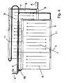
- Fig. 2 is a first embodiment of an inventive device for air conditioning shown schematically. This embodiment differs from the prior art in particular in that the ejector 4 is arranged adjacent to the first evaporator 5.
- any arrangement of the ejector is conceivable, wherein the ejector in Fig. 2 is shown only schematically and may have any configuration according to the prior art.
- the ejector may be arranged above or below the first or second evaporator.
- the first and second evaporator and the ejector form a structural unit.
- the first and second evaporators each have an upper and lower collecting duct 14 and partitions 11, so that the two evaporators are flowed through in several flutes with refrigerant (indicated by arrows K).
- the two evaporators are flown with air to be cooled (indicated by arrow L), wherein the second evaporator 8 is arranged in the air flow direction in front of the first evaporator 5.
- the device has a separating element 7 which separates the refrigerant flow into a first partial stream flowing to the first evaporator 5 and a second partial stream flowing to the second evaporator 8.
- the separation of the two streams to the two evaporators can be such that no significant differences in the liquid content arise or that the liquid content of the first partial stream is greater than the liquid content of the second partial stream.
- the separation is carried out in the simplest case by a branch pipe or, for example, by a vertical baffle, as long as the refrigerant flow still flows along the main axis of the ejector.
- phase-separating elements such as baffles, nonwovens, mesh or other packings may be arranged.
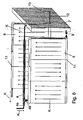
- Fig. 3 and Fig. 4 show two further embodiments of a device according to the invention for air conditioning.
- the two evaporators are flowed through in three floods.
- a flow through the evaporator in four, five, six or any other number of floods possible, the two evaporators may each have an equal or different number of floods.
- Flows of the first and second evaporators, which are arranged one behind the other in the direction of air flow, are flowed through in opposite directions. additionally the refrigerant outlets are arranged on different sides.
- Such an arrangement has the advantage that thus overheating zones which form in the region of the refrigerant outlets of the evaporator, occur on different sides of the evaporator, so that their influence on the temperature profile of the air to be cooled is not increased, but partially or completely canceled ,
- Fig. 5 shows in particular a further embodiment of a separating element 7.
- the separated liquid collects in the lower region of the separating element and is supplied from there via the expansion element 9 to the first evaporator 5.
- the end of the suction duct 13 may be mounted geodetically lower, so that in the event that more liquid is deposited than flows through the expansion device 9, the remaining part of the liquid can flow into the second evaporator 8, before the large volume of the separating element is filled.
- Fig. 6 shows in particular a further embodiment of a separating element 7.
- the refrigerant intake of the second evaporator 8 is in this case geodetically higher than that of the first evaporator 5, so that in the first evaporator always preferred liquid refrigerant flows.
- the end of the suction line 13 may be designed such that liquid is not suddenly sucked into the second evaporator 8.
- the end of the suction line may be slotted or have a plurality of inlet bores.
- a plurality of suction lines 12 at different Be provided points of the separating element 7.
- Several intake pipes can also be used in the embodiments according to FIG Fig. 5 .
- Fig. 10 and Fig. 11 be attached to different locations of the separating element 7.
- the separating element 7 internals, such as sheets, which prevent sloshing of the liquid.
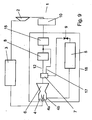
- Fig. 7 shows a further embodiment of a device according to the invention.
- This device has a second separating element 19, in particular a phase-separating separating element.
- the first separating element 7 may be formed as a pipe branch, so that the first and second partial stream downstream of the first separating element 7 may essentially have an equal liquid content.
- the second separating element 19 is communicatively connected to a line which communicates the second evaporator 8 downstream with the low-pressure accumulator 10, so that the vapor deposited in the second separating element 19 is fed downstream of the second evaporator 8.
- Such an arrangement has the advantage that the second separating element 19 can be operated with a pressure drop in the same size as in the second evaporator 8.
- a third evaporator 15 is arranged downstream of the second evaporator 8.
- the second phase-separating separator 19 is communicatively connected to a line communicatively connecting the second and third evaporators.
- the phase-separating separator 19 can thus with a Pressure drop according to the second evaporator 8 are operated.
- the first phase-separating separator 7 is communicatively connected by a conduit 17 to a conduit communicatively connecting the second and third evaporators. In this case, it is possible to dispense with the second separating element 19.
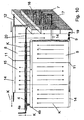
- Fig. 10 shows a further embodiment, or a concretization of the embodiment according to Fig. 9 , in which the second 8 and third 15 evaporator form a structural unit, so that a compact and space-saving design is possible.
- the phase-separating first separating element 7 in this case has a dense packing made of fleece or other phase-separating packs 16.
- the line 17 opens into the lower collecting channel 14 of the second evaporator eighth
- the second evaporator 8 can also be designed as a pipeline to the third evaporator 15.
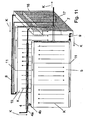
- Such an embodiment, which in Fig. 11 is shown is particularly advantageous if constructive conditions already result in a significant pressure drop of such a line between the separator 7 and the third evaporator 15.
- Fig. 12 shows a detailed view of a first separation element 7 according to the invention with the corresponding supply lines and leads, which in Fig. 10 are shown. It will be readily apparent to those skilled in the art that primarily liquid will be drawn through the conduit 19 into the first evaporator 5 because the end of the conduit 17 is above the liquid level 21.
- both the ejector and the first, second and third evaporator, the expansion element 9 and the first and / or second separating element may be formed into a structural unit 18.
- the device according to the invention is not limited to a specific refrigerant.
- the device in addition to the refrigerant R134a, the device is also suitable for the refrigerant R744.
- the device comprises an internal heat exchanger, which further improves the efficiency.
Description
Die Erfindung betrifft eine Vorrichtung zur Luftkonditionierung für ein Kraftfahrzeug nach dem Oberbegriff des Anspruchs 1.The invention relates to a device for air conditioning for a motor vehicle according to the preamble of
Die
Die
Es ist Aufgabe der Erfindung, eine Vorrichtung zur Luftkonditionierung für ein Kraftfahrzeug zu schaffen, bei der die
Diese Aufgabe wird für eine eingangs genannte Vorrichtung mit den kennzeichnenden Merkmalen des Anspruchs 1 gelöst. Vorteilhafte Ausgestaltungen sind Gegenstand der Unteransprüche.This object is achieved for an aforementioned device with the characterizing features of
Durch die benachbarte Anordnung des Ejektors zum ersten und/oder zweiten Verdampfer sind eine Verkürzung der zu- und abführenden Kältemittelleitungen und eine Minimierung von Umlenkungen möglich. Damit können neben einer Kostenersparnis und einer erheblichen Verringerung des Montageaufwandes große Druckabfälle und Entmischungseffekte des Kältemittels vermieden werden. Zusätzlich wird mit der erfindungsgemäßen Anordnung Bauraum eingespart.Due to the adjacent arrangement of the ejector to the first and / or second evaporator, a shortening of the incoming and outgoing refrigerant lines and a minimization of deflections are possible. Thus, in addition to cost savings and a significant reduction in assembly costs, large pressure drops and segregation effects of the refrigerant can be avoided. In addition, space is saved with the arrangement according to the invention.
Der Begriff "benachbart" ist erfindungsgemäß breit auszulegen. Erfindungsgemäß kann der Ejektor mit dem ersten und/oder zweiten Verdampfer eine Baueinheit bilden oder in unmittelbarer Nähe des ersten und/oder zweiten Verdampfers angeordnet sein.The term "adjacent" is to be interpreted broadly according to the invention. According to the invention, the ejector with the first and / or second evaporator a Form assembly form or be arranged in the immediate vicinity of the first and / or second evaporator.
Der Ejektor kann sich je nach bauraumbedingten Anforderungen oberhalb oder unterhalb des ersten und/oder zweiten Verdampfers befinden. In alternativer Ausführung kann der Ejektor in Einbaulage vor oder hinter dem ersten und/oder zweiten Verdampfer angeordnet sein. Hierbei ist eine Anordnung vorstellbar, bei der der Ejektor waagrecht, senkrecht oder diagonal verläuft.The ejector may be located above or below the first and / or second evaporator depending on space requirements. In an alternative embodiment, the ejector can be arranged in the installed position in front of or behind the first and / or second evaporator. Here, an arrangement is conceivable in which the ejector is horizontal, vertical or diagonal.
In einer besonders bevorzugten Ausführungsform sind der erste und zweite Verdampfer als eine Baueinheit ausgebildet und insbesondere verlötet oder verschweißt oder durch ein anderes stoffschlüssiges Verfahren zusammengefügt.In a particularly preferred embodiment, the first and second evaporator are formed as a structural unit and in particular soldered or welded or joined together by another cohesive method.
Bevorzugt ist der zweite Verdampfer in Luftströmungsrichtung vor dem ersten Verdampfer angeordnet.Preferably, the second evaporator is arranged in the air flow direction in front of the first evaporator.
Erfindungsgemäß werden der erste und zweite Verdampfer mehrflutig durchströmt. Mehrflutig im Sinne der Erfindung bedeutet, dass ein Verdampfer mindestens zwei Rohrgruppen oder Fluten aufweist, die von einem Kältemittel durchströmbar sind. Bevorzugt werden hierbei benachbarte Fluten entgegengesetzt durchströmt. Die einzelnen Fluten bestehen aus mehreren Rohren, insbesondere Flachrohren. Bevorzugt sind zwischen den Rohren, Rippen, insbesondere Wellrippen angeordnet, um den Wärmeübergang zwischen dem zu kühlenden Fluid, insbesondere Luft, und dem Kältemittel zu verbessern.According to the invention, the first and second evaporators are flowed through in multiple floods. Multi-flush in the sense of the invention means that an evaporator has at least two pipe groups or floods, which can be traversed by a refrigerant. In this case, adjacent flows are preferably flowed through in opposite directions. The individual floods consist of several tubes, in particular flat tubes. Preferably, between the tubes, ribs, in particular corrugated fins are arranged to improve the heat transfer between the fluid to be cooled, in particular air, and the refrigerant.
Erfindungsgemäß werden die beiden Verdampfer in Richtung senkrecht zu den Fluten entgegengesetzt durchströmt. Mit anderen Worten: Die jeweiligen Ausgänge der beiden Verdampfer befinden sich auf unterschiedlichen Seiten. Durch eine derartige erfindungsgemäße Durchströmung der beiden Verdampfer können Überhitzungszonen, die sich bei bestimmten Betriebszuständen im Verdampfer ausbilden teilweise oder gänzlich aufgehoben werden. Somit wird ein homogenes Temperaturprofil des zu kühlenden Fluides erreicht.According to the invention, the two evaporators are flowed through in the opposite direction in the direction perpendicular to the floods. In other words: The respective outputs of the two evaporators are located on different sides. By such a flow according to the invention of the two evaporators overheating zones that form in certain operating conditions in the evaporator can be partially or completely canceled. Thus, a homogeneous temperature profile of the fluid to be cooled is achieved.
In einer alternativen Ausführungsform der Erfindung ist abströmseitig des Ejektors ein Trennelement angeordnet. Das Trennelement kann beispielsweise als Rohrverzweigung, Umlenkblech, Vlies oder Gitter ausgebildet sein. Selbstverständlich ist auch ein beliebig anderes Element vorstellbar, das den Kältemittelstrom in einen ersten zum ersten Verdampfer strömenden Teilstrom und in einen zweiten zum zweiten Verdampfer strömenden Teilstrom aufteilt. Die Auftrennung der beiden Teilströme kann derart erfolgen, dass der erste Teilstrom einen im Wesentlichen gleichen oder einen größeren Flüssigkeitsanteil besitzt als der zweite Teilstrom.In an alternative embodiment of the invention, a separating element is arranged downstream of the ejector. The separating element may be formed, for example, as a pipe branching, deflecting plate, fleece or grid. Of course, any other element is conceivable that divides the refrigerant flow into a first partial flow flowing to the first evaporator and into a second partial flow flowing to the second evaporator. The separation of the two partial flows can be carried out such that the first partial flow has a substantially equal or greater liquid content than the second partial flow.
In einer weiteren Ausführungsform ist abströmseitig des zweiten Verdampfers ein dritter Verdampfer angeordnet. Bevorzugt bildet der zweite Verdampfer mit dem dritten Verdampfer eine Baueinheit.In a further embodiment, a third evaporator is arranged downstream of the second evaporator. Preferably, the second evaporator with the third evaporator forms a structural unit.
In einer weiteren Ausführungsform ist abströmseitig des ersten Trennelementes und zuströmseitig des ersten Verdampfers ein zweites Trennelement, insbesondere ein phasenseparierendes Trennelement, angeordnet. Besonders bevorzugt ist das zweite Trennelement kommunizierend mit einer Leitung verbunden, die den zweiten und dritten Verdampfer kommunizierend miteinander verbindet. Durch diese Anordnung können Flüssigkeitsanteile des ersten Teilstromes, die nicht im ersten Verdampfer abgeschieden werden, im dritten Verdampfer verdampfen und somit zur Optimierung des Gesamtsystems beitragen.In a further embodiment, a second separating element, in particular a phase-separating separating element, is arranged downstream of the first separating element and upstream of the first evaporator. Particularly preferably, the second separating element is communicatively connected to a line which connects the second and third evaporators communicating with each other. By virtue of this arrangement, liquid fractions of the first substream which are not deposited in the first evaporator can evaporate in the third evaporator and thus contribute to the optimization of the overall system.
In einer weiteren Ausführungsform ist abströmseitig des zweiten oder des dritten Verdampfers und zuströmseitig des Verdichters ein Sammler und/oder ein innerer Wärmeübertrager angeordnet.In a further embodiment, a collector and / or an internal heat exchanger is arranged downstream of the second or the third evaporator and upstream of the compressor.
In vielen Versuchen hat sich herausgestellt, dass eine etwaige Überhitzungszone am luftaustriftsseitigen Verdampfer (erster Verdampfer) sich negativ auf einen Leistungsgewinn des Ejektors auswirkt.In many experiments, it has been found that any overheating zone on the air outlet-side evaporator (first evaporator) has a negative effect on a performance gain of the ejector.
Es wird daher ein Verfahren vorgeschlagen, bei dem ein Durchflusswert eines Drosselelementes zuströmseitig des ersten Verdampfers derart eingestellt wird, dass am ersten Verdampfer in allen Betriebspunkten keine Überhitzungszone auftritt. Der Durchflusswert ist hierbei abhängig vom verwendeten Kältemittel und ob zuströmseitig des Drosselementes eine Phasentrennung vorgesehen ist oder nicht.Therefore, a method is proposed in which a flow value of a throttle element is adjusted on the inflow side of the first evaporator in such a way that no overheating zone occurs at the first evaporator in all operating points. The flow rate here depends on the refrigerant used and whether upstream of the throttle element, a phase separation is provided or not.
Für verschiedene Kältemittel ergeben sich folgende Durchflusswerte für das Drosselelement, wobei der Durchflusswert durch eine Kennzahl A ![]()
- m: Massenstrom
- d: Dichte des Kältemittels
- p: Druckabfall über das Drosselelement
- m: mass flow
- d: density of the refrigerant
- p: Pressure drop across the throttle element
Derartige Durchflusskennzahlen beziehen sich auf eine Vorrichtung zur Luftkonditionierung mittlerer Leistungsklasse. Typische Werte der Durchflusskennzahl A für kleinere und größere Leistungsklasse bewegen sich in einem Bereich von 0,1*A bis 10*A, bevorzugt in einem Bereich 0,5*A bis 2*A.Such flowcharacteristics relate to a device for air conditioning of medium power class. Typical values of the flow index A for smaller and larger performance classes are in the range from 0.1 * A to 10 * A, preferably in a range from 0.5 * A to 2 * A.
Die Durchflusskennzahl A des Drosselelementes wird bevorzugt im Betrieb nicht verändert und bezieht sich beispielsweise auf ein Ventil mit Blende.The flow index A of the throttle element is preferably not changed during operation and refers for example to a valve with orifice.
Alternativ kann jedoch auch ein Drosselelement mit im Betrieb verstellbarer Durchflusskennzahl eingesetzt werden.Alternatively, however, it is also possible to use a throttle element with a flow rate variable during operation.
Es versteht sich, dass die vorstehend genannten und die nachstehend noch zu erläuternden Merkmale nicht nur in der jeweils angegebenen Kombination, sondern auch in anderen Kombinationen oder in Alleinstellung verwendbar sind, ohne den Rahmen der vorliegenden Erfindung zu verlassen.It is understood that the features mentioned above and those yet to be explained not only in the combination specified in each case, but also in other combinations or alone, without departing from the scope of the present invention.
Weitere wichtige Merkmale der vorliegenden Erfindung ergeben sich aus der nachfolgenden detaillierten Beschreibung in Verbindung mit den Ansprüchen und den Zeichnungen.Further important features of the present invention will become apparent from the following detailed description taken in conjunction with the claims and the drawings.
Nachfolgend werden bevorzugte Ausführungsbeispiele einer erfindungsgemäßen Vorrichtung zur Luftkonditionierung beschrieben und anhand der anliegenden Zeichnungen näher erläutert.Hereinafter, preferred embodiments of a device according to the invention for air conditioning will be described and explained in more detail with reference to the accompanying drawings.
Es zeigen:
-
Fig. 1 eine schematische Darstellung einer Vorrichtung zur Luftkonditionierung nach dem Stand der Technik; -
Fig. 2 einen schematischen Ausschnitt eines erstes Ausführungsbeispiel einer erfindungsgemäßen Vorrichtung zur Luftkonditionierung; -
Fig. 3 einen schematischen Ausschnitt eines zweites Ausführungsbeispiel einer erfindungsgemäßen Vorrichtung; -
Fig. 4 einen schematischen Ausschnitt eines dritten Ausführungsbeispiels einer erfindungsgemäßen Vorrichtung; -
Fig. 5 einen schematischen Ausschnitt eines vierten Ausführungsbeispiels einer erfindungsgemäßen Vorrichtung; -
Fig. 6 einen schematischen Ausschnitt eines fünften Ausführungsbeispiels einer erfindungsgemäßen Vorrichtung; -
Fig. 7 eine schematische Darstellung eines sechsten Ausführungsbeispiels einer erfindungsgemäßen Vorrichtung; -
Fig. 8 eine schematische Darstellung eines siebenten Ausführungsbeispiels einer erfindungsgemäßen Vorrichtung; -
Fig. 9 eine schematische Darstellung eines achten Ausführungsbeispiels einer erfindungsgemäßen Vorrichtung; -
Fig. 10 einen schematischen Ausschnitt eines neunten Ausführungsbeispiels einer erfindungsgemäßen Vorrichtung; -
Fig. 11 einen schematischen Ausschnitt eines zehnten Ausführungsbeispiels einer erfindungsgemäßen Vorrichtung; -
Fig. 12 eine Detailansicht eines erfindungsgemäßen Trennelementes;
-
Fig. 1 a schematic representation of a device for air conditioning according to the prior art; -
Fig. 2 a schematic section of a first embodiment of an apparatus according to the invention for air conditioning; -
Fig. 3 a schematic section of a second embodiment of a device according to the invention; -
Fig. 4 a schematic section of a third embodiment of a device according to the invention; -
Fig. 5 a schematic section of a fourth embodiment of a device according to the invention; -
Fig. 6 a schematic section of a fifth embodiment of a device according to the invention; -
Fig. 7 a schematic representation of a sixth embodiment of a device according to the invention; -
Fig. 8 a schematic representation of a seventh embodiment of a device according to the invention; -
Fig. 9 a schematic representation of an eighth embodiment of a device according to the invention; -
Fig. 10 a schematic section of a ninth embodiment of a device according to the invention; -
Fig. 11 a schematic section of a tenth embodiment of a device according to the invention; -
Fig. 12 a detailed view of a separating element according to the invention;
In
Der erste und zweite Verdampfer weisen jeweils einen oberen und unteren Sammelkanal 14 und Trennwände 11 auf, so dass die beiden Verdampfer mehrflutig mit Kältemittel (durch Pfeile K angedeutet) durchströmt werden. Die beiden Verdampfer werden mit zu kühlender Luft (durch Pfeil L angedeutet) beströmt, wobei der zweite Verdampfer 8 in Luftströmungsrichtung vor dem ersten Verdampfer 5 angeordnet ist.The first and second evaporators each have an upper and lower collecting
Ferner weist die Vorrichtung ein Trennelement 7 auf, das den Kältemittelstrom in einen ersten zum ersten Verdampfer 5 strömenden Teilstrom und einen zweiten zum zweiten Verdampfer 8 strömenden Teilstrom trennt. Die Auftrennung der beiden Ströme zu den beiden Verdampfern kann derart erfolgen, dass keine wesentlichen Unterschiede im Flüssigkeitsgehalt entstehen oder dass der Flüssigkeitsgehalt des ersten Teilstromes größer ist als der Flüssigkeitsgehalt des zweiten Teilstromes. Die Auftrennung erfolgt im einfachsten Fall durch eine Rohrverzweigung oder beispielsweise durch ein vertikales Leitblech, solange der Kältemittelstrom noch entlang der Hauptachse des Ejektors strömt. Für den Fall dass der erste Teilstrom einen höheren Flüssigkeitsgehalt aufweisen soll als der zweite Teilstrom, können phasentrennende Elemente wie Umlenkbleche, Vliese, Gitter oder sonstige Packungen angeordnet sein.Furthermore, the device has a separating
Die
In einem weiteren nicht gezeigten Ausführungsbeispiel weist das Trennelement 7 Einbauten, beispielsweise Bleche, auf, die ein Schwappen der Flüssigkeit verhindern.In a further embodiment, not shown, the separating
Die
In einer Weiterführung der Ausführungsform gemäß
In einer besonders bevorzugten Ausführungsform können sowohl der Ejektor als auch der erste, zweite und dritte Verdampfer, das Expansionsorgan 9 und das erste und/oder zweite Trennelement zu einer Baueinheit 18 ausgebildet sein.In a particularly preferred embodiment, both the ejector and the first, second and third evaporator, the
Die erfindungsgemäße Vorrichtung ist nicht auf ein bestimmtes Kältemittel beschränkt. Beispielsweise eignet sich die Vorrichtung neben dem Kältemittel R134a auch für das Kältemittel R744. In erstem und insbesondere in zweitem Falle umfasst die Vorrichtung einen inneren Wärmeübertrager, der den Wirkungsgrad weiter verbessert.The device according to the invention is not limited to a specific refrigerant. For example, in addition to the refrigerant R134a, the device is also suitable for the refrigerant R744. In the first and especially in the second case, the device comprises an internal heat exchanger, which further improves the efficiency.
Anstatt des Niederdrucksammlers 10 wäre auch eine Ausführungsform mit einem Hochdrucksammler und einer Überhitzungsregelung denkbar.Instead of the low-
Claims (13)
- An air conditioning device for a motor vehicle (1), comprising a compressor (2) for compressing a refrigerant which is supplied on the suction side, a heat exchanger (3), in particular a condenser, disposed downstream of the compressor in the flow direction of the refrigerant, an ejector (4) disposed downstream of the radiator, wherein the ejector comprises a first inlet (4a) for the inflow of refrigerant from the heat exchanger (3) and at least one second inlet (4b) for the inflow of refrigerant in a state that differs from the first inlet and differs in terms of pressure in particular, and wherein the ejector (4) comprises an outlet for the emission of a mixture of the two inlets, and comprising a first evaporator (5), wherein at least a portion of the refrigerant emitted from the outlet can be supplied to the first evaporator (5), and wherein the refrigerant leaving the first evaporator can be supplied, at least partially, to the second inlet (4b) of the ejector (4), and comprising a second evaporator (8), wherein a portion of the refrigerant emitted from the outlet of the ejector (4) can be supplied to the second evaporator (8), and the refrigerant leaving the second evaporator can be supplied to the suction side of the compressor, wherein the first and the second evaporator are passed through by a fluid to be cooled, air in particular, wherein the ejector is disposed adjacently to the first and/or the second evaporator, characterized in that
partitions (11) are disposed in the first and the second evaporator such that refrigerant flows through the evaporator in a plurality of flutes, and flow travels in opposite directions through the first and the second evaporator in a direction perpendicular to the flutes. - The device according to claim 1, characterized in that the first (5) and the second (8) evaporator form one assembly.
- The device according to claim 1, characterized in that flow occurs in opposite directions in adjacent flutes of an evaporator.
- The device according to one of the preceding claims, characterized in that a third evaporator (15) is disposed on the outflow side of the second evaporator (8).
- The device according to claim 4, characterized in that the second and the third evaporator are designed as one assembly.
- The device according to one of the preceding claims, characterized in that a first separating element (7) is disposed on the outflow side of the ejector (4) which divides the refrigerant flow into a first partial stream and a second partial stream.
- The device according to claim 6, characterized in that the fluid content of the first partial stream is greater than or substantially equal to the fluid content of the second partial stream.
- The device as recited in one of the claims 6 or 7, characterized in that the first separating element forms an assembly with the ejector (4).
- The device according to one of the claims 6 to 8, characterized in that the separating element is connected in a communicating manner to a line that connects the second and the third evaporator in a communicating manner.
- The device according to one of the preceding claims, characterized in that a second separating element (19) is disposed on the outflow side of the first separating element and on the inflow side of the first evaporator.
- The device according to claim 10, characterized in that the second separating element is connected in a communicating manner to a line that connects the second and the third evaporator in a communicating manner.
- The device according to claim 10, characterized in that the second separating element is connected to a line that connects the second evaporator to the compressor in a communicating manner.
- A method for operating a device according to one of the preceding claims, characterized in that a throttle element (9) is disposed on the inflow side of the first evaporator (5), and a flow factor A of the throttle element is set such that an overheating zone does not occur at the first evaporator (5) at any operating point of the device.
Priority Applications (2)
| Application Number | Priority Date | Filing Date | Title |
|---|---|---|---|
| EP10166322A EP2230113B1 (en) | 2007-10-16 | 2008-10-16 | Air conditioning device for a motor vehicle |
| EP10166312A EP2223815B1 (en) | 2007-10-16 | 2008-10-16 | Air conditioning device for a motor vehicle |
Applications Claiming Priority (1)
| Application Number | Priority Date | Filing Date | Title |
|---|---|---|---|
| DE102007049823 | 2007-10-16 |
Related Child Applications (2)
| Application Number | Title | Priority Date | Filing Date |
|---|---|---|---|
| EP10166312.8 Division-Into | 2010-06-17 | ||
| EP10166322.7 Division-Into | 2010-06-17 |
Publications (3)
| Publication Number | Publication Date |
|---|---|
| EP2050601A2 EP2050601A2 (en) | 2009-04-22 |
| EP2050601A3 EP2050601A3 (en) | 2009-05-06 |
| EP2050601B1 true EP2050601B1 (en) | 2011-01-19 |
Family
ID=40244691
Family Applications (3)
| Application Number | Title | Priority Date | Filing Date |
|---|---|---|---|
| EP10166322A Expired - Fee Related EP2230113B1 (en) | 2007-10-16 | 2008-10-16 | Air conditioning device for a motor vehicle |
| EP10166312A Expired - Fee Related EP2223815B1 (en) | 2007-10-16 | 2008-10-16 | Air conditioning device for a motor vehicle |
| EP08018143A Expired - Fee Related EP2050601B1 (en) | 2007-10-16 | 2008-10-16 | Air conditioning device for a motor vehicle |
Family Applications Before (2)
| Application Number | Title | Priority Date | Filing Date |
|---|---|---|---|
| EP10166322A Expired - Fee Related EP2230113B1 (en) | 2007-10-16 | 2008-10-16 | Air conditioning device for a motor vehicle |
| EP10166312A Expired - Fee Related EP2223815B1 (en) | 2007-10-16 | 2008-10-16 | Air conditioning device for a motor vehicle |
Country Status (2)
| Country | Link |
|---|---|
| EP (3) | EP2230113B1 (en) |
| DE (2) | DE502008002371D1 (en) |
Families Citing this family (6)
| Publication number | Priority date | Publication date | Assignee | Title |
|---|---|---|---|---|
| DE102009050886A1 (en) | 2009-10-27 | 2011-04-28 | Behr Gmbh & Co. Kg | evaporator module |
| DE102010031388A1 (en) | 2010-07-15 | 2012-01-19 | Behr Gmbh & Co. Kg | Expansion element, useful for a system for air conditioning for motor vehicle, comprises inlet portion with two inputs to supply refrigerant in two states, outlet portion with two outputs to discharge refrigerant, and elongated mixing tube |
| DE102010031391A1 (en) | 2010-07-15 | 2012-01-19 | Behr Gmbh & Co. Kg | Evaporator module for refrigerant circuit of air conditioner in car, has ejector including two inputs, cladding link, and common output, where refrigerant supply is integrated in cladding link of ejector |
| JP5699263B2 (en) * | 2010-11-16 | 2015-04-08 | 株式会社テージーケー | Control valve used in vehicle air conditioner |
| DE102013100457A1 (en) * | 2013-01-17 | 2014-07-17 | Dr. Ing. H.C. F. Porsche Aktiengesellschaft | System for carrying refrigerant of air conditioning apparatus, has casing which is provided with inner and outer media guides which are separated by preset space in which nitrogen and carbon dioxide are arranged |
| CN107074072B (en) * | 2015-06-30 | 2019-06-25 | 翰昂汽车零部件有限公司 | Outdoor heat exchanger |
Family Cites Families (7)
| Publication number | Priority date | Publication date | Assignee | Title |
|---|---|---|---|---|
| DE4036854C1 (en) * | 1990-11-19 | 1992-05-21 | Thermal-Werke, Waerme-, Kaelte-, Klimatechnik Gmbh, 6832 Hockenheim, De | |
| JP4016659B2 (en) * | 2002-01-15 | 2007-12-05 | 株式会社デンソー | Air conditioner |
| JP4595607B2 (en) * | 2005-03-18 | 2010-12-08 | 株式会社デンソー | Refrigeration cycle using ejector |
| JP4626531B2 (en) * | 2005-04-01 | 2011-02-09 | 株式会社デンソー | Ejector refrigeration cycle |
| DE102005021396A1 (en) | 2005-05-04 | 2006-11-09 | Behr Gmbh & Co. Kg | Device for air conditioning for a motor vehicle |
| DE102006022557A1 (en) * | 2005-05-16 | 2006-11-23 | Denso Corp., Kariya | Ejektorpumpenkreisvorrichtung |
| DE102006011327A1 (en) * | 2006-03-09 | 2007-09-13 | Behr Gmbh & Co. Kg | Heat exchanger with cold storage |
-
2008
- 2008-10-16 EP EP10166322A patent/EP2230113B1/en not_active Expired - Fee Related
- 2008-10-16 DE DE502008002371T patent/DE502008002371D1/en active Active
- 2008-10-16 EP EP10166312A patent/EP2223815B1/en not_active Expired - Fee Related
- 2008-10-16 DE DE102008051892A patent/DE102008051892A1/en not_active Withdrawn
- 2008-10-16 EP EP08018143A patent/EP2050601B1/en not_active Expired - Fee Related
Also Published As
| Publication number | Publication date |
|---|---|
| EP2223815B1 (en) | 2011-10-12 |
| DE102008051892A1 (en) | 2009-05-20 |
| EP2230113B1 (en) | 2011-10-12 |
| EP2050601A2 (en) | 2009-04-22 |
| DE502008002371D1 (en) | 2011-03-03 |
| EP2050601A3 (en) | 2009-05-06 |
| EP2223815A1 (en) | 2010-09-01 |
| EP2230113A1 (en) | 2010-09-22 |
Similar Documents
| Publication | Publication Date | Title |
|---|---|---|
| EP2050601B1 (en) | Air conditioning device for a motor vehicle | |
| EP1719650B1 (en) | Air conditioning unit for a vehicle | |
| DE102011015838B4 (en) | evaporator unit | |
| EP2815186B1 (en) | Device for cooling and/or heat recovery | |
| DE102008005077B4 (en) | Plate evaporator, especially for a refrigerant circuit | |
| DE3028304A1 (en) | HEAT EXCHANGER | |
| DE112016003070T5 (en) | Cooling system and cooling system in the vehicle | |
| DE10123347B4 (en) | Heat exchanger with phase change of refrigerant | |
| EP2135025B1 (en) | Heat exchanger for evaporating a liquid portion of a medium having a bypass for an evaporated portion of the medium | |
| DE102017211256A1 (en) | Refrigeration system for a vehicle with a heat exchanger having a refrigerant circuit and heat exchanger for such a refrigeration system | |
| DE102017211736A1 (en) | capacitor | |
| EP3313678B1 (en) | Evaporator unit for a rooftop air-conditioning system of a road-going vehicle | |
| DE112015003615T5 (en) | Evaporator | |
| DE102005059917A1 (en) | Evaporator | |
| DE10322165B4 (en) | Refrigerant-cooling heat exchanger | |
| EP2165867A1 (en) | Evaporator with condensed water overflow protection | |
| DE112006003241T5 (en) | heat exchangers | |
| EP2316674B1 (en) | Evaporator module | |
| EP2757340B1 (en) | Cooler | |
| DE10352337A1 (en) | Heat exchanger for use in motor vehicle, especially in air-conditioning system, has fluid supply line and fluid outlet line, two heat exchanger units, and flow-connecting device | |
| DE102013100884A1 (en) | Internal heat exchanger with desiccant | |
| DE102021213376A1 (en) | Heat exchanger and refrigerant circuit with a heat exchanger | |
| DE102016219205A1 (en) | Multi-pass air / refrigerant heat exchanger, air conditioning device for a motor vehicle and motor vehicle | |
| EP1293736A1 (en) | Coolant system for a vehicle air conditioner and cooling device for the coolant system | |
| DE102022201204A1 (en) | heat exchanger module |
Legal Events
| Date | Code | Title | Description |
|---|---|---|---|
| PUAI | Public reference made under article 153(3) epc to a published international application that has entered the european phase |
Free format text: ORIGINAL CODE: 0009012 |
|
| PUAL | Search report despatched |
Free format text: ORIGINAL CODE: 0009013 |
|
| AK | Designated contracting states |
Kind code of ref document: A2 Designated state(s): AT BE BG CH CY CZ DE DK EE ES FI FR GB GR HR HU IE IS IT LI LT LU LV MC MT NL NO PL PT RO SE SI SK TR |
|
| AX | Request for extension of the european patent |
Extension state: AL BA MK RS |
|
| AK | Designated contracting states |
Kind code of ref document: A3 Designated state(s): AT BE BG CH CY CZ DE DK EE ES FI FR GB GR HR HU IE IS IT LI LT LU LV MC MT NL NO PL PT RO SE SI SK TR |
|
| AX | Request for extension of the european patent |
Extension state: AL BA MK RS |
|
| 17P | Request for examination filed |
Effective date: 20091106 |
|
| 17Q | First examination report despatched |
Effective date: 20091130 |
|
| AKX | Designation fees paid |
Designated state(s): DE FR GB |
|
| GRAP | Despatch of communication of intention to grant a patent |
Free format text: ORIGINAL CODE: EPIDOSNIGR1 |
|
| GRAS | Grant fee paid |
Free format text: ORIGINAL CODE: EPIDOSNIGR3 |
|
| GRAA | (expected) grant |
Free format text: ORIGINAL CODE: 0009210 |
|
| AK | Designated contracting states |
Kind code of ref document: B1 Designated state(s): DE FR GB |
|
| REG | Reference to a national code |
Ref country code: GB Ref legal event code: FG4D Free format text: NOT ENGLISH |
|
| REF | Corresponds to: |
Ref document number: 502008002371 Country of ref document: DE Date of ref document: 20110303 Kind code of ref document: P |
|
| REG | Reference to a national code |
Ref country code: DE Ref legal event code: R096 Ref document number: 502008002371 Country of ref document: DE Effective date: 20110303 |
|
| PLBE | No opposition filed within time limit |
Free format text: ORIGINAL CODE: 0009261 |
|
| STAA | Information on the status of an ep patent application or granted ep patent |
Free format text: STATUS: NO OPPOSITION FILED WITHIN TIME LIMIT |
|
| 26N | No opposition filed |
Effective date: 20111020 |
|
| REG | Reference to a national code |
Ref country code: DE Ref legal event code: R097 Ref document number: 502008002371 Country of ref document: DE Effective date: 20111020 |
|
| GBPC | Gb: european patent ceased through non-payment of renewal fee |
Effective date: 20121016 |
|
| PG25 | Lapsed in a contracting state [announced via postgrant information from national office to epo] |
Ref country code: GB Free format text: LAPSE BECAUSE OF NON-PAYMENT OF DUE FEES Effective date: 20121016 |
|
| REG | Reference to a national code |
Ref country code: DE Ref legal event code: R082 Ref document number: 502008002371 Country of ref document: DE Representative=s name: GRAUEL, ANDREAS, DIPL.-PHYS. DR. RER. NAT., DE |
|
| REG | Reference to a national code |
Ref country code: DE Ref legal event code: R082 Ref document number: 502008002371 Country of ref document: DE Representative=s name: GRAUEL, ANDREAS, DIPL.-PHYS. DR. RER. NAT., DE Effective date: 20150303 Ref country code: DE Ref legal event code: R081 Ref document number: 502008002371 Country of ref document: DE Owner name: MAHLE INTERNATIONAL GMBH, DE Free format text: FORMER OWNER: BEHR GMBH & CO. KG, 70469 STUTTGART, DE Effective date: 20150303 |
|
| REG | Reference to a national code |
Ref country code: FR Ref legal event code: PLFP Year of fee payment: 8 |
|
| REG | Reference to a national code |
Ref country code: FR Ref legal event code: PLFP Year of fee payment: 9 |
|
| REG | Reference to a national code |
Ref country code: FR Ref legal event code: PLFP Year of fee payment: 10 |
|
| REG | Reference to a national code |
Ref country code: FR Ref legal event code: PLFP Year of fee payment: 11 |
|
| PGFP | Annual fee paid to national office [announced via postgrant information from national office to epo] |
Ref country code: DE Payment date: 20181030 Year of fee payment: 11 |
|
| PGFP | Annual fee paid to national office [announced via postgrant information from national office to epo] |
Ref country code: FR Payment date: 20181026 Year of fee payment: 11 |
|
| REG | Reference to a national code |
Ref country code: DE Ref legal event code: R119 Ref document number: 502008002371 Country of ref document: DE |
|
| PG25 | Lapsed in a contracting state [announced via postgrant information from national office to epo] |
Ref country code: DE Free format text: LAPSE BECAUSE OF NON-PAYMENT OF DUE FEES Effective date: 20200501 |
|
| PG25 | Lapsed in a contracting state [announced via postgrant information from national office to epo] |
Ref country code: FR Free format text: LAPSE BECAUSE OF NON-PAYMENT OF DUE FEES Effective date: 20191031 |