EP2629014A2 - Brennermantel-Führungsanschlag und Verfahren zur Montage eines Brenners - Google Patents
Brennermantel-Führungsanschlag und Verfahren zur Montage eines Brenners Download PDFInfo
- Publication number
- EP2629014A2 EP2629014A2 EP13155371.1A EP13155371A EP2629014A2 EP 2629014 A2 EP2629014 A2 EP 2629014A2 EP 13155371 A EP13155371 A EP 13155371A EP 2629014 A2 EP2629014 A2 EP 2629014A2
- Authority
- EP
- European Patent Office
- Prior art keywords
- liner
- combustor
- stop
- casing
- guide stop
- Prior art date
- Legal status (The legal status is an assumption and is not a legal conclusion. Google has not performed a legal analysis and makes no representation as to the accuracy of the status listed.)
- Withdrawn
Links
- 238000002485 combustion reaction Methods 0.000 title claims abstract description 64
- 238000000034 method Methods 0.000 title claims description 23
- 230000008878 coupling Effects 0.000 claims description 4
- 238000010168 coupling process Methods 0.000 claims description 4
- 238000005859 coupling reaction Methods 0.000 claims description 4
- 238000003466 welding Methods 0.000 claims description 3
- 239000012530 fluid Substances 0.000 claims description 2
- 239000007789 gas Substances 0.000 description 16
- 230000013011 mating Effects 0.000 description 12
- 230000000295 complement effect Effects 0.000 description 7
- 238000001816 cooling Methods 0.000 description 3
- 239000000446 fuel Substances 0.000 description 3
- 238000009434 installation Methods 0.000 description 3
- 230000008439 repair process Effects 0.000 description 3
- 230000004048 modification Effects 0.000 description 2
- 238000012986 modification Methods 0.000 description 2
- 230000035882 stress Effects 0.000 description 2
- 230000008646 thermal stress Effects 0.000 description 2
- 230000007704 transition Effects 0.000 description 2
- 239000000567 combustion gas Substances 0.000 description 1
- 230000003247 decreasing effect Effects 0.000 description 1
- 238000005516 engineering process Methods 0.000 description 1
- 239000000463 material Substances 0.000 description 1
- 238000011144 upstream manufacturing Methods 0.000 description 1
Images


Classifications
-
- F—MECHANICAL ENGINEERING; LIGHTING; HEATING; WEAPONS; BLASTING
- F23—COMBUSTION APPARATUS; COMBUSTION PROCESSES
- F23R—GENERATING COMBUSTION PRODUCTS OF HIGH PRESSURE OR HIGH VELOCITY, e.g. GAS-TURBINE COMBUSTION CHAMBERS
- F23R3/00—Continuous combustion chambers using liquid or gaseous fuel
- F23R3/002—Wall structures
-
- F—MECHANICAL ENGINEERING; LIGHTING; HEATING; WEAPONS; BLASTING
- F23—COMBUSTION APPARATUS; COMBUSTION PROCESSES
- F23R—GENERATING COMBUSTION PRODUCTS OF HIGH PRESSURE OR HIGH VELOCITY, e.g. GAS-TURBINE COMBUSTION CHAMBERS
- F23R3/00—Continuous combustion chambers using liquid or gaseous fuel
- F23R3/42—Continuous combustion chambers using liquid or gaseous fuel characterised by the arrangement or form of the flame tubes or combustion chambers
- F23R3/60—Support structures; Attaching or mounting means
-
- F—MECHANICAL ENGINEERING; LIGHTING; HEATING; WEAPONS; BLASTING
- F23—COMBUSTION APPARATUS; COMBUSTION PROCESSES
- F23R—GENERATING COMBUSTION PRODUCTS OF HIGH PRESSURE OR HIGH VELOCITY, e.g. GAS-TURBINE COMBUSTION CHAMBERS
- F23R2900/00—Special features of, or arrangements for continuous combustion chambers; Combustion processes therefor
- F23R2900/00017—Assembling combustion chamber liners or subparts
-
- Y—GENERAL TAGGING OF NEW TECHNOLOGICAL DEVELOPMENTS; GENERAL TAGGING OF CROSS-SECTIONAL TECHNOLOGIES SPANNING OVER SEVERAL SECTIONS OF THE IPC; TECHNICAL SUBJECTS COVERED BY FORMER USPC CROSS-REFERENCE ART COLLECTIONS [XRACs] AND DIGESTS
- Y10—TECHNICAL SUBJECTS COVERED BY FORMER USPC
- Y10T—TECHNICAL SUBJECTS COVERED BY FORMER US CLASSIFICATION
- Y10T29/00—Metal working
- Y10T29/49—Method of mechanical manufacture
- Y10T29/49229—Prime mover or fluid pump making
- Y10T29/49231—I.C. [internal combustion] engine making
Definitions
- the present subject matter relates generally to a combustion liner guide stop of gas turbine combustor, and particularly to combustion liner guide stop inserted through a combustor casing and a method for assembling the combustor.
- Gas turbines typically include a compressor section, a combustion section, and a turbine section.
- the compressor section pressurizes air flowing into the turbine.
- the pressurized air discharged from the compressor section flows into the combustion section, which is generally characterized by a plurality of combustors disposed around an annular array about the axis of the gas turbine.
- Each of the plurality of combustors includes a combustion liner, which defines the combustion chamber of the combustor.
- air entering each combustor is mixed with fuel and combusted within the combustion liner. Hot combustion gases flow from the combustion liner through a transition piece to the turbine section of the gas turbine to drive the turbine and generate power.
- the combustion liner is typically concentrically located within a flow sleeve of the combustor and radially inwardly spaced therefrom.
- the forward end of the combustion liner is generally provided with a plurality of circumferentially spaced liner stop features (i.e., male or female liner stops) which engage and/or mate with a corresponding number of liner guide stops typically secured to the flow sleeve.
- liner stop features i.e., male or female liner stops
- the liner stops ensure proper radial and axial location of the combustion liner within the flow sleeve and also prevent the combustion liner from moving in an axially downstream direction (i.e., towards the transition piece).
- combustor dynamics and thermal stresses may cause the combustion liner, the flow sleeve and other components of the combustor to vibrate and otherwise move with respect to one another. This can lead to failure of the liner stop features and/or the liner guide stops, thereby resulting in misalignment of the combustion liner within the flow sleeve and/or damage to the combustion liner or flow sleeve.
- the combustor In order to repair the damaged liner guide stops, the combustor must be taken offline and at least partially disassembled. The combustion liner and/or the flow sleeve have to be removed and a worker must machine the damaged component on site, or send the parts off-site for repair resulting in costly repairs and extended outage periods. Accordingly, an improved combustor liner guide stop for a gas turbine combustor and a method for installing the liner guide stop would be welcomed in the technology.
- the present invention resides in a combustor for a gas turbine.
- the combustor includes a casing, a flow sleeve at least partially disposed within the casing, a combustion liner at least partially disposed within the flow sleeve, a liner stop feature extending from the combustion liner, and a liner guide stop.
- the liner guide stop includes a first end separated from a second end. The second end may be configured to at least partially engage the liner stop feature, and the liner guide stop extends through the casing and the flow sleeve.
- the present invention resides in a method for assembling a combustor of a gas turbine, the combustor including a casing, a flow sleeve and a combustion liner.
- the method generally includes inserting the combustion liner into the combustor casing, wherein the combustion liner includes at least one liner stop feature extending from the combustion liner.
- the method may also include inserting a liner guide stop through the casing and the flow sleeve, wherein the liner guide stop extends between a first end and a second end, and engaging the second end of the liner guide stop with the liner stop feature.
- the present subject matter is generally directed to a gas turbine combustor including a casing, a flow sleeve, a combustion liner and a liner guide stop.
- the present subject matter is also directed to a method for assembling the combustor.
- the liner guide stop passes through the casing and the flow sleeve and engages with a liner stop feature extending generally radially from the combustion liner.
- the combustion liner may be properly aligned and supported within the combustor during assembly and operation of the combustor.
- the liner guide stop may be coupled to an outer surface of the casing.
- the liner guide stop may be removed and/or replaced through the casing without requiring disassembly of the combustor, thereby saving operators considerable expenses, such as labor and material and lost revenue costs generally associated with extended outages.
- the liner guide stop may be passed through the casing and the flow sleeve rather than mechanically coupling it directly to the flow sleeve, mechanical and thermal stresses may be significantly reduced on the flow sleeve. As a result, the period between outages may be extended, thus further reducing operating expenses incurred by operators.
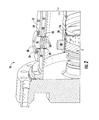
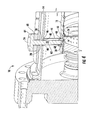
- Figs. 1-4 illustrate cross-sectional side views of a portion of a gas turbine combustor 10 according to various embodiments of the present invention.
- the combustor 10 may include a generally annular casing 12.
- the casing 12 may be secured to a portion of a gas turbine casing (not shown), such as a compressor discharge casing or a combustion wrapper casing.
- the combustor 10 may also include a flow sleeve 14 and a combustion liner 16 substantially concentrically arranged within the flow sleeve 14.
- the combustor 10 may further include an end cover 18 disposed at one end of the casing 12 and may also include a fuel nozzle cap assembly 20 disposed generally within the combustion liner 16.
- the combustor 10 may also include at least one liner guide stop 22 including a first end 24 and a second end 26.
- the combustion liner 16 may generally define a substantially cylindrical combustion chamber, wherein fuel and air are injected and combusted to produce hot gases of combustion.
- the casing 12 may define at least one first passage 28 extending generally radially through the casing 12.
- the casing 12 may also define a first mating surface 30 disposed on an outer surface 32 of the casing 12.
- the first mating surface 30 may at least partially surround the first passage 28.
- the first mating surface 30 and/or the casing 12 may be configured to receive a complementary threaded fastener, such as a bolt (not shown).
- the first mating surface 30 may include at least one recess 34 extending generally radially inward from the first mating surface 30.
- the recess 34 may be tapped and/or may be configured to receive a threaded insert.
- the first passage 28 may be configured to allow the liner guide stop 22 to be coupled directly to the casing 12.
- the first passage 28 may be tapped and/or configured to receive a threaded insert.
- a first collar 36 may be disposed substantially concentrically within the first passage 28.
- the first collar 36 may extend generally radially inward and through the casing 12.
- the first collar 36 may at least partially surround the liner guide stop 22 shown in Figs. 1 , 3 and 4 .
- the first collar 36 may extend through the casing 12 and the flow sleeve 14.
- the first collar 36 may be generally arcuate, rectangular, triangular and/or any shape complementary to the first passage 24.
- the first collar 36 may prevent the liner guide stop 22 from damaging the first passage 28 and/or the flow sleeve 14 during assembly and operation of the combustor 10 by providing a boundary surface between the liner guide stop 22 and the casing 12 and/or the flow sleeve 14.
- the first collar 36 may help to guide the liner guide stop 22 through the casing 12 and/or the flow sleeve 14 during assembly of the combustor 10.
- the first collar 36 may at least partially define a plurality of cooling passages 38 extending therethrough. In this manner, a working fluid, such as compressor discharge air, may flow through the plurality of cooling passages 38 and provide convective cooling of the liner guide stop 22 shown in Figs. 1 , 3 and 4 , during operation of the combustor, thereby decreasing thermal and mechanical stresses on the liner guide stop 22.
- the flow sleeve 14 may define at least one second passage 40 extending generally radially through the flow sleeve 14.
- the second passage 40 may be aligned substantially concentrically with the first passage 28.
- the second passage 40 may be generally arcuate, rectangular, triangular or any shape complementary to the liner guide stop 22 and/or the first collar 36 as shown in Fig. 2 . In this manner, the liner guide stop 22 and/or the first collar 36 may extend through the flow sleeve 14.
- the second passage 40 may be sized to allow for thermal growth of the liner guide stop during operation of the combustor 10 and/or to allow for the removal/replacement of the liner guide stop during combustor 10 outages.
- a second collar 42 may be disposed generally concentrically within the second passage 40.
- the second collar 42 may extend generally radially through the flow sleeve 14 and may be mechanically coupled to the flow sleeve 14.
- the second collar 42 may be welded or brazed to the flow sleeve 14.
- the second collar 42 may be inserted into the second passage 40 and allowed to float within the second passage 40.
- the second collar 42 may move within the second passage 40 to allow for misalignment of the flow sleeve 14, misalignment of the liner guide stop 22, to account for variations in assembly tolerances, to allow for movement of the flow sleeve 14 and/or the liner guide stop 22 during operation of the combustor 10 and/or to reduce the mechanical stresses between the flow sleeve 14 and the liner guide stop 22.
- an alignment sleeve 44 may extend generally radially inward from an inner surface 46 of the flow sleeve 14 towards the combustion liner 16. It should be appreciated that the alignment sleeve 44 may be coupled to the flow sleeve 14 using any suitable means known in the art. For example, the alignment sleeve 44 may be welded, bolted, pinned, and/or cast as an integral part of the flow sleeve 14. The alignment sleeve 44 may at least partially surround the second passage 40 and/or the first collar 36 or the second collar 42, as shown in Figs. 2 and 1 respectfully. The alignment sleeve 44 may be partially arcuate, triangular, or rectangular or any combination thereof suitable to at least partially engage and/or align the flow sleeve 14 with the combustion liner 16 during assembly and/or operation of the combustor 10.
- the combustion liner 16 may include at least one liner stop feature 48.
- the liner stop feature 48 may be coupled to the combustion liner 16 and may extend generally radially outward from a cool side surface 50 of the combustion liner 16. It should be appreciated by one skilled in the art that the liner stop feature 48 may be coupled to the combustion liner 16 using any suitable means known in the art. For example, the liner stop feature 48 may be welded, pined and/or cast as an integral part of the combustion liner 16. As shown in Figs.
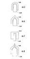
- the liner stop feature 48 may be designed to have any suitable shape and/or configuration that may enable the liner stop feature 48 to mate and/or engage with the liner guide stop 22 second end 26 and/or the alignment sleeve 44 as shown in Fig. 3 , so as to facilitate installation of the combustion liner 16 and/or to properly align the combustion liner 16 within the flow sleeve 14 (or combustion casing 12) and/or to prevent rotation and/or axial movement of the combustion liner 16 during operation of the combustor 10.
- second end as used herein is defined as a portion of the liner guide stop 22 that at least partially engages with the liner stop feature 48. For example, as shown in Figs.
- the liner stop feature 48 may be generally arcuate, triangular, rectangular or any combination thereof suitable for engaging and/or mating with the liner guide stop 22 second end 26 as shown in Figs. 1 , 3 and 4 and/or for engaging with the alignment sleeve 44 as shown in Fig. 3 .
- the liner stop feature 48 may be configured as male or female liner stop features 48 so as to complement the liner guide stop 22 second end 26.
- the liner stop feature 48 may define a first elongated slot 52 configured to receive the liner guide stop 22 second end 26 as the combustion liner 16 is inserted into the combustor 10.
- the first elongated slot 52 may be generally defined from a downstream end 54 of the liner stop feature 48 and may extend towards an upstream end 56 of the liner stop feature 48.
- the liner stop feature 48 may at least partially define a hole 58 extending generally radially inward from a top surface 60 of the liner stop feature 48.
- the hole 58 may be tapped and/or may include a threaded insert configured to engage with the liner guide stop 22 second end 26.
- the liner guide stop includes a support body 62 generally extending between the first end 24 and the second end 26.
- the support body 62 may generally extend through the casing 12 first passage 28 and the flow sleeve 14 second passage 40 so that the second end 26 at least partially engages with the liner stop feature 48 of the combustion liner 16.
- the support body 62 may be generally arcuate, rectangular, angled or any shape or combination of shapes suitable for supporting the combustion liner 16 during operation of the combustor 10.
- the first end 24 of the liner guide stop 22 may include a flange 64 extending at least partially circumferentially around the first end 24.
- the flange 64 may define at least one fastener passage 66 extending generally radially through the flange 64.
- the fastener passage 66 may be positioned so as to be aligned with the casing 12 recess 34 when the liner guide stop 22 is inserted into the combustor 10. In this manner, a fastener, such as a bolt, may pass through the flange 64 and into the casing 12 recess 34 in order to couple the liner guide stop 22 to the casing 12.
- the support body 62 and/or the first end 24 may be threaded.
- the liner guide stop 22 may be secured directly to the casing 12 by screwing the liner guide stop 22 into the first passage 28, wherein the first passage 28 is threaded and/or includes threaded inserts disposed within the first passage 28 as previously disclosed.
- the flange 64 may also define a second mating surface 68.
- the second mating surface 68 may be complementary to the first mating surface 30 of the casing 12 shown in Fig. 2 , and may form a seal between the liner guide stop 22 and the casing 12 as shown in Figs.
- the liner guide stop 22 may be coupled to the casing 12 and/or the first mating surface 30 by welding the liner guide stop 22 to the outer surface 32 of the casing 12 and/or to the first mating surface 30.
- the liner guide stop 22 may be coupled to an outer surface of the flow sleeve 14. In this manner, the support body 62 may extend through the flow sleeve 14 so that the second end 26 at least partially engages with the liner stop feature 48 of the combustion liner 16.
- the second end 26 of the liner guide stop 22 may be any suitable shape and/or configuration that enables the liner guide stop 22 to mate and/or engage with the liner stop feature 48 so as to facilitate installation of the combustion liner 16 and/or to properly align the combustion liner 16 within the flow sleeve 14 and/or the combustor casing 12. In this manner, the liner guide stop 22 may also prevent rotation and/or axial movement of the combustion liner 16 during operation of the combustor 10.
- the liner guide stop 22 may be generally arcuate, triangular, rectangular or any combination thereof suitable for engaging and/or mating with the liner stop feature 48. As shown in Figs.
- the liner guide stop 22 second end 26 may be configured to complement the male or female liner stop feature 48.
- the second end 26 of the liner guide stop 22 may include a second elongated slot 70 such that the liner stop feature 48 may slide into and at least partially engage the liner guide stop 22 second end 26 as the combustion liner 16 is installed within the combustor 10.
- the second end may be generally circular and may include threads extending at least partially circumferentially around the second end 26. The threads on the second end 26 may be complementary to the threads disposed within the hole 58 of the liner stop feature 48.
- liner guide stop 22 may be screwed into the liner stop feature 48 to provide support and/or to maintain proper alignment of the combustion liner 16 during assembly and operation of the combustor 10. It should be appreciated by one skilled in the art that liner guide stop 22 may be utilized to indicate the proper installation depth of the combustion liner 16 as well as prevent rotation and/or axial movement of the combustion liner 16 during operation of the combustor 10.
- the various embodiments described and illustrated with respect to Figs. 1-8 may also provide a method for assembling the combustor 10 for a gas turbine.
- the method may generally include inserting the combustion liner 16, comprising at least one of the liner stop features 48, into the combustor casing 12.
- the method further includes inserting the liner guide stop 22 through the casing 12 and the flow sleeve 14, and engaging the second end 26 of the liner guide stop 22 with the liner stop feature 48.
- the method may further include coupling the first end 24 of the liner guide stop 22 to the casing 12.
- the method may also include coupling the liner guide stop 22 to the casing 12 by bolting or welding the liner guide stop 22 to an outer surface 32 of the casing 12.
- the method may further include inserting a collar (36 or 42) through at least one of the casing 12 or the flow sleeve 14 so that the collar at least partially surrounds the liner guide stop 22.
- the method may also include screwing the liner guide stop 22 into the liner stop feature 48.
- the method may further include inserting the liner stop feature 48 into the second elongated slot 70 disposed at the second end 26 of the liner guide stop 22.
- the method may include inserting the liner guide stop 22 into the first elongated slot 52 disposed within the liner stop feature 48.
- the method may also include aligning the liner stop feature 48 with the alignment sleeve 44 as the combustion liner 16 is inserted into the flow sleeve 14.
Landscapes
- Engineering & Computer Science (AREA)
- Chemical & Material Sciences (AREA)
- Combustion & Propulsion (AREA)
- Mechanical Engineering (AREA)
- General Engineering & Computer Science (AREA)
- Turbine Rotor Nozzle Sealing (AREA)
- Gas Burners (AREA)
Applications Claiming Priority (1)
| Application Number | Priority Date | Filing Date | Title |
|---|---|---|---|
| US13/400,264 US9435535B2 (en) | 2012-02-20 | 2012-02-20 | Combustion liner guide stop and method for assembling a combustor |
Publications (2)
| Publication Number | Publication Date |
|---|---|
| EP2629014A2 true EP2629014A2 (de) | 2013-08-21 |
| EP2629014A3 EP2629014A3 (de) | 2015-10-21 |
Family
ID=47710032
Family Applications (1)
| Application Number | Title | Priority Date | Filing Date |
|---|---|---|---|
| EP13155371.1A Withdrawn EP2629014A3 (de) | 2012-02-20 | 2013-02-15 | Brennermantel-Führungsanschlag und Verfahren zur Montage eines Brenners |
Country Status (5)
| Country | Link |
|---|---|
| US (1) | US9435535B2 (de) |
| EP (1) | EP2629014A3 (de) |
| JP (1) | JP2013170814A (de) |
| CN (1) | CN103256628B (de) |
| RU (1) | RU2013107152A (de) |
Cited By (1)
| Publication number | Priority date | Publication date | Assignee | Title |
|---|---|---|---|---|
| WO2016156285A1 (en) * | 2015-03-30 | 2016-10-06 | Nuovo Pignone Tecnologie Srl | Interchangeable liner support for gas turbine combustors |
Families Citing this family (7)
| Publication number | Priority date | Publication date | Assignee | Title |
|---|---|---|---|---|
| EP2735796B1 (de) * | 2012-11-23 | 2020-01-01 | Ansaldo Energia IP UK Limited | WAND EINER HEIßGASDURCHGANGSKOMPONENTE EINER GASTURBINE UND VERFAHREN ZUM VERSTÄRKEN DES BETRIEBSVERHALTENS EINER GASTURBINE |
| WO2014179328A1 (en) * | 2013-04-29 | 2014-11-06 | United Technologies Corporation | Joint for sealing a gap between casing segments of an industrial gas turbine engine combustor |
| US9696037B2 (en) * | 2014-10-16 | 2017-07-04 | General Electric Company | Liner retaining feature for a combustor |
| US10634349B2 (en) * | 2015-08-24 | 2020-04-28 | General Electric Company | Wear pad system for turbine combustion systems and method for coupling wear pad into turbine combustion system |
| US11092083B2 (en) * | 2017-02-10 | 2021-08-17 | General Electric Company | Pressure sensor assembly for a turbine engine |
| US11248797B2 (en) * | 2018-11-02 | 2022-02-15 | Chromalloy Gas Turbine Llc | Axial stop configuration for a combustion liner |
| US11377970B2 (en) | 2018-11-02 | 2022-07-05 | Chromalloy Gas Turbine Llc | System and method for providing compressed air to a gas turbine combustor |
Family Cites Families (39)
| Publication number | Priority date | Publication date | Assignee | Title |
|---|---|---|---|---|
| US3116606A (en) | 1958-07-21 | 1964-01-07 | Gen Motors Corp | Combustion can support |
| US3372542A (en) | 1966-11-25 | 1968-03-12 | United Aircraft Corp | Annular burner for a gas turbine |
| US3481316A (en) | 1967-12-01 | 1969-12-02 | Caterpillar Tractor Co | Cylinder liner support with improved cooling |
| US3911672A (en) * | 1974-04-05 | 1975-10-14 | Gen Motors Corp | Combustor with ceramic liner |
| US4195476A (en) * | 1978-04-27 | 1980-04-01 | General Motors Corporation | Combustor construction |
| JPS59113663U (ja) * | 1983-01-19 | 1984-08-01 | 株式会社日立製作所 | 燃焼器の支持構造 |
| JPS6329118A (ja) * | 1986-07-23 | 1988-02-06 | Hitachi Ltd | ガスタ−ビン燃焼器 |
| US4903476A (en) * | 1988-12-27 | 1990-02-27 | General Electric Company | Gas turbine igniter with ball-joint support |
| JPH0589849U (ja) * | 1991-03-29 | 1993-12-07 | 本田技研工業株式会社 | ガスタービンエンジン |
| FR2686683B1 (fr) * | 1992-01-28 | 1994-04-01 | Snecma | Turbomachine a chambre de combustion demontable. |
| US5323600A (en) | 1993-08-03 | 1994-06-28 | General Electric Company | Liner stop assembly for a combustor |
| DE19751299C2 (de) * | 1997-11-19 | 1999-09-09 | Siemens Ag | Brennkammer sowie Verfahren zur Dampfkühlung einer Brennkammer |
| US6216442B1 (en) | 1999-10-05 | 2001-04-17 | General Electric Co. | Supports for connecting a flow sleeve and a liner in a gas turbine combustor |
| GB2355302B (en) * | 1999-10-13 | 2003-12-31 | Rolls Royce Plc | Gas turbine engines |
| US6279313B1 (en) | 1999-12-14 | 2001-08-28 | General Electric Company | Combustion liner for gas turbine having liner stops |
| US6499993B2 (en) * | 2000-05-25 | 2002-12-31 | General Electric Company | External dilution air tuning for dry low NOX combustors and methods therefor |
| US6331110B1 (en) * | 2000-05-25 | 2001-12-18 | General Electric Company | External dilution air tuning for dry low NOx combustors and methods therefor |
| US6415610B1 (en) * | 2000-08-18 | 2002-07-09 | Siemens Westinghouse Power Corporation | Apparatus and method for replacement of combustor basket swirlers |
| FR2826102B1 (fr) * | 2001-06-19 | 2004-01-02 | Snecma Moteurs | Perfectionnements apportes aux chambres de combustion de turbine a gaz |
| US6843061B2 (en) * | 2002-02-15 | 2005-01-18 | Siemens Westinghouse Power Corporation | Gas turbine with flexible combustion sensor connection |
| US6895761B2 (en) | 2002-12-20 | 2005-05-24 | General Electric Company | Mounting assembly for the aft end of a ceramic matrix composite liner in a gas turbine engine combustor |
| ITMI20031673A1 (it) | 2003-08-28 | 2005-02-28 | Nuovo Pignone Spa | Sistema di fissaggio di un tubo di fiamma o "liner". |
| US7338244B2 (en) * | 2004-01-13 | 2008-03-04 | Siemens Power Generation, Inc. | Attachment device for turbine combustor liner |
| US7389643B2 (en) * | 2005-01-31 | 2008-06-24 | General Electric Company | Inboard radial dump venturi for combustion chamber of a gas turbine |
| US7581402B2 (en) * | 2005-02-08 | 2009-09-01 | Siemens Energy, Inc. | Turbine engine combustor with bolted swirlers |
| US7082766B1 (en) | 2005-03-02 | 2006-08-01 | General Electric Company | One-piece can combustor |
| US7647779B2 (en) | 2005-04-27 | 2010-01-19 | United Technologies Corporation | Compliant metal support for ceramic combustor liner in a gas turbine engine |
| US7523616B2 (en) | 2005-11-30 | 2009-04-28 | General Electric Company | Methods and apparatuses for assembling a gas turbine engine |
| US7493771B2 (en) * | 2005-11-30 | 2009-02-24 | General Electric Company | Methods and apparatuses for assembling a gas turbine engine |
| US7637110B2 (en) * | 2005-11-30 | 2009-12-29 | General Electric Company | Methods and apparatuses for assembling a gas turbine engine |
| US7571611B2 (en) | 2006-04-24 | 2009-08-11 | General Electric Company | Methods and system for reducing pressure losses in gas turbine engines |
| US7762075B2 (en) | 2007-08-14 | 2010-07-27 | General Electric Company | Combustion liner stop in a gas turbine |
| US20090255268A1 (en) * | 2008-04-11 | 2009-10-15 | General Electric Company | Divergent cooling thimbles for combustor liners and related method |
| US8303243B2 (en) * | 2009-01-15 | 2012-11-06 | Pratt & Whitney Canada Corp. | Turbine wash port for a gas turbine engine |
| US8171737B2 (en) | 2009-01-16 | 2012-05-08 | General Electric Company | Combustor assembly and cap for a turbine engine |
| US20120036857A1 (en) * | 2010-08-10 | 2012-02-16 | General Electric Company | Combustion liner stop blocks having insertable wear features and related methods |
| CN202101276U (zh) | 2011-05-18 | 2012-01-04 | 中国科学院工程热物理研究所 | 燃气轮机柔和燃烧室 |
| US9249732B2 (en) * | 2012-09-28 | 2016-02-02 | United Technologies Corporation | Panel support hanger for a turbine engine |
| CA2900654C (en) * | 2013-03-07 | 2020-03-31 | Rolls-Royce Corporation | Flexible bellows igniter seal for a gas turbine with a ceramic combustion liner |
-
2012
- 2012-02-20 US US13/400,264 patent/US9435535B2/en not_active Expired - Fee Related
-
2013
- 2013-02-15 EP EP13155371.1A patent/EP2629014A3/de not_active Withdrawn
- 2013-02-18 JP JP2013028503A patent/JP2013170814A/ja not_active Ceased
- 2013-02-20 RU RU2013107152/06A patent/RU2013107152A/ru unknown
- 2013-02-20 CN CN201310054795.XA patent/CN103256628B/zh not_active Expired - Fee Related
Non-Patent Citations (1)
| Title |
|---|
| None |
Cited By (4)
| Publication number | Priority date | Publication date | Assignee | Title |
|---|---|---|---|---|
| WO2016156285A1 (en) * | 2015-03-30 | 2016-10-06 | Nuovo Pignone Tecnologie Srl | Interchangeable liner support for gas turbine combustors |
| CN107850304A (zh) * | 2015-03-30 | 2018-03-27 | 诺沃皮尼奥内技术股份有限公司 | 用于燃气涡轮燃烧室的可互换内衬支撑件 |
| US10753610B2 (en) | 2015-03-30 | 2020-08-25 | Nuovo Pignone Srl | Interchangeable liner support for gas turbine combusters |
| CN107850304B (zh) * | 2015-03-30 | 2022-06-24 | 诺沃皮尼奥内技术股份有限公司 | 用于燃气涡轮燃烧室的可互换内衬支撑件 |
Also Published As
| Publication number | Publication date |
|---|---|
| CN103256628A (zh) | 2013-08-21 |
| US9435535B2 (en) | 2016-09-06 |
| JP2013170814A (ja) | 2013-09-02 |
| EP2629014A3 (de) | 2015-10-21 |
| US20130213047A1 (en) | 2013-08-22 |
| RU2013107152A (ru) | 2014-08-27 |
| CN103256628B (zh) | 2016-09-14 |
Similar Documents
| Publication | Publication Date | Title |
|---|---|---|
| US9435535B2 (en) | Combustion liner guide stop and method for assembling a combustor | |
| US9400114B2 (en) | Combustor support assembly for mounting a combustion module of a gas turbine | |
| US9316155B2 (en) | System for providing fuel to a combustor | |
| US9631812B2 (en) | Support frame and method for assembly of a combustion module of a gas turbine | |
| US20140260318A1 (en) | Side seal slot for a combustion liner | |
| US7805946B2 (en) | Combustor flow sleeve attachment system | |
| US20120036857A1 (en) | Combustion liner stop blocks having insertable wear features and related methods | |
| EP2636952A2 (de) | Kraftstoffdüse und Brennkammer für eine Gasturbine | |
| US9416969B2 (en) | Gas turbine transition inlet ring adapter | |
| US20150027126A1 (en) | System for providing fuel to a combustor | |
| US9273868B2 (en) | System for supporting bundled tube segments within a combustor | |
| EP2530381A2 (de) | Stützelement für einen Überleitkanal in einem Turbinensystem | |
| US9423136B2 (en) | Bundled tube fuel injector aft plate retention | |
| US20150308349A1 (en) | Fuel delivery system | |
| CN106089439B (zh) | 燃气涡轮拆卸方法 | |
| US20180073738A1 (en) | Annular combustor for a gas turbine engine | |
| EP2543850A1 (de) | Anordnung zur Halterung einer Turbinenbaugruppe und zugehörige Turbinenbaugruppe | |
| US10697634B2 (en) | Inner cooling shroud for transition zone of annular combustor liner | |
| US20140334925A1 (en) | System for supporting a turbine nozzle | |
| JP7571117B2 (ja) | ガスタービンエンジンの燃焼器構成要素のための軸方向保持アセンブリ | |
| EP2543824A1 (de) | Anordnung zur Halterung einer Turbinenbaugruppe und zugehörige Turbinenbaugruppe | |
| EP3221642B1 (de) | Lanzeninjektor zur einspritzung von kraftstoff in eine brennkammer einer gasturbine | |
| US20150059177A1 (en) | Method for removing an end cap of a combustor cap assembly | |
| CN114096784A (zh) | 用于燃气涡轮发动机的燃烧器部件的轴向保持组件 |
Legal Events
| Date | Code | Title | Description |
|---|---|---|---|
| PUAI | Public reference made under article 153(3) epc to a published international application that has entered the european phase |
Free format text: ORIGINAL CODE: 0009012 |
|
| AK | Designated contracting states |
Kind code of ref document: A2 Designated state(s): AL AT BE BG CH CY CZ DE DK EE ES FI FR GB GR HR HU IE IS IT LI LT LU LV MC MK MT NL NO PL PT RO RS SE SI SK SM TR |
|
| AX | Request for extension of the european patent |
Extension state: BA ME |
|
| PUAL | Search report despatched |
Free format text: ORIGINAL CODE: 0009013 |
|
| AK | Designated contracting states |
Kind code of ref document: A3 Designated state(s): AL AT BE BG CH CY CZ DE DK EE ES FI FR GB GR HR HU IE IS IT LI LT LU LV MC MK MT NL NO PL PT RO RS SE SI SK SM TR |
|
| AX | Request for extension of the european patent |
Extension state: BA ME |
|
| RIC1 | Information provided on ipc code assigned before grant |
Ipc: F23R 3/00 20060101AFI20150914BHEP Ipc: F23R 3/60 20060101ALI20150914BHEP |
|
| 17P | Request for examination filed |
Effective date: 20160421 |
|
| RBV | Designated contracting states (corrected) |
Designated state(s): AL AT BE BG CH CY CZ DE DK EE ES FI FR GB GR HR HU IE IS IT LI LT LU LV MC MK MT NL NO PL PT RO RS SE SI SK SM TR |
|
| 17Q | First examination report despatched |
Effective date: 20171010 |
|
| STAA | Information on the status of an ep patent application or granted ep patent |
Free format text: STATUS: THE APPLICATION IS DEEMED TO BE WITHDRAWN |
|
| 18D | Application deemed to be withdrawn |
Effective date: 20180221 |