EP2628672B1 - Tilt control for tilting vehicles - Google Patents
Tilt control for tilting vehicles Download PDFInfo
- Publication number
- EP2628672B1 EP2628672B1 EP13168191.8A EP13168191A EP2628672B1 EP 2628672 B1 EP2628672 B1 EP 2628672B1 EP 13168191 A EP13168191 A EP 13168191A EP 2628672 B1 EP2628672 B1 EP 2628672B1
- Authority
- EP
- European Patent Office
- Prior art keywords
- damper
- vehicle
- steering
- sensor
- rheologic
- Prior art date
- Legal status (The legal status is an assumption and is not a legal conclusion. Google has not performed a legal analysis and makes no representation as to the accuracy of the status listed.)
- Active
Links
- 239000000725 suspension Substances 0.000 claims description 38
- 239000012530 fluid Substances 0.000 claims description 30
- 238000013016 damping Methods 0.000 claims description 23
- 230000001133 acceleration Effects 0.000 claims description 8
- 230000035939 shock Effects 0.000 claims description 5
- 239000006096 absorbing agent Substances 0.000 claims description 4
- 238000010586 diagram Methods 0.000 description 4
- 230000000694 effects Effects 0.000 description 4
- 241001465754 Metazoa Species 0.000 description 1
- 239000000654 additive Substances 0.000 description 1
- 230000000996 additive effect Effects 0.000 description 1
- 230000007423 decrease Effects 0.000 description 1
- 230000002708 enhancing effect Effects 0.000 description 1
- 230000002349 favourable effect Effects 0.000 description 1
- 239000000446 fuel Substances 0.000 description 1
- 238000009499 grossing Methods 0.000 description 1
- 238000012986 modification Methods 0.000 description 1
- 230000004048 modification Effects 0.000 description 1
- 238000003825 pressing Methods 0.000 description 1
- 238000004804 winding Methods 0.000 description 1
Images


Classifications
-
- B—PERFORMING OPERATIONS; TRANSPORTING
- B62—LAND VEHICLES FOR TRAVELLING OTHERWISE THAN ON RAILS
- B62K—CYCLES; CYCLE FRAMES; CYCLE STEERING DEVICES; RIDER-OPERATED TERMINAL CONTROLS SPECIALLY ADAPTED FOR CYCLES; CYCLE AXLE SUSPENSIONS; CYCLE SIDE-CARS, FORECARS, OR THE LIKE
- B62K5/00—Cycles with handlebars, equipped with three or more main road wheels
- B62K5/10—Cycles with handlebars, equipped with three or more main road wheels with means for inwardly inclining the vehicle body on bends
-
- B—PERFORMING OPERATIONS; TRANSPORTING
- B62—LAND VEHICLES FOR TRAVELLING OTHERWISE THAN ON RAILS
- B62J—CYCLE SADDLES OR SEATS; AUXILIARY DEVICES OR ACCESSORIES SPECIALLY ADAPTED TO CYCLES AND NOT OTHERWISE PROVIDED FOR, e.g. ARTICLE CARRIERS OR CYCLE PROTECTORS
- B62J45/00—Electrical equipment arrangements specially adapted for use as accessories on cycles, not otherwise provided for
- B62J45/40—Sensor arrangements; Mounting thereof
- B62J45/41—Sensor arrangements; Mounting thereof characterised by the type of sensor
- B62J45/415—Inclination sensors
- B62J45/4151—Inclination sensors for sensing lateral inclination of the cycle
-
- B—PERFORMING OPERATIONS; TRANSPORTING
- B62—LAND VEHICLES FOR TRAVELLING OTHERWISE THAN ON RAILS
- B62K—CYCLES; CYCLE FRAMES; CYCLE STEERING DEVICES; RIDER-OPERATED TERMINAL CONTROLS SPECIALLY ADAPTED FOR CYCLES; CYCLE AXLE SUSPENSIONS; CYCLE SIDE-CARS, FORECARS, OR THE LIKE
- B62K5/00—Cycles with handlebars, equipped with three or more main road wheels
- B62K5/02—Tricycles
- B62K5/027—Motorcycles with three wheels
-
- B—PERFORMING OPERATIONS; TRANSPORTING
- B62—LAND VEHICLES FOR TRAVELLING OTHERWISE THAN ON RAILS
- B62K—CYCLES; CYCLE FRAMES; CYCLE STEERING DEVICES; RIDER-OPERATED TERMINAL CONTROLS SPECIALLY ADAPTED FOR CYCLES; CYCLE AXLE SUSPENSIONS; CYCLE SIDE-CARS, FORECARS, OR THE LIKE
- B62K5/00—Cycles with handlebars, equipped with three or more main road wheels
- B62K5/02—Tricycles
- B62K5/05—Tricycles characterised by a single rear wheel
-
- B—PERFORMING OPERATIONS; TRANSPORTING
- B62—LAND VEHICLES FOR TRAVELLING OTHERWISE THAN ON RAILS
- B62K—CYCLES; CYCLE FRAMES; CYCLE STEERING DEVICES; RIDER-OPERATED TERMINAL CONTROLS SPECIALLY ADAPTED FOR CYCLES; CYCLE AXLE SUSPENSIONS; CYCLE SIDE-CARS, FORECARS, OR THE LIKE
- B62K5/00—Cycles with handlebars, equipped with three or more main road wheels
- B62K5/08—Cycles with handlebars, equipped with three or more main road wheels with steering devices acting on two or more wheels
Definitions
- the present invention relates to tilt control for tilting vehicles.
- Tilting vehicles are subject to overturning transversely due to transverse forces such as side wind forces, transverse gravitational force components, and centrifugal forces.
- Active tilt control systems have been proposed to prevent transverse overturning. Such systems generally include transverse actuators to force the vehicle to tilt transversely to counteract transverse forces on the vehicle.
- Some existing solutions comprise a mechanical brake being in a brake state or open state, a manually operated tilt control.
- the solution usually is just a plausibility check that doesn't comprise any sensors to measure tilt angle or tilt rate and it can be activated either manually or by using a plausibility check, for example in case of an acceleration of the vehicle.
- Active tilt control systems are complicated and expensive.
- WO 02/068228 A1 reveals a tilting vehicle according to the preamble of claim 1, including a frame freely titable transversely between at least two spaced wheels, at least one variable damper with adjustable damping force operatively connected between the frame and the two wheels and at least one sensor being an acceleration sensor, a braking-circuit pressure sensor, an inclination sensor, a steering sensor or a fuel flow rate sensor to generate signals indicative of transverse tilting of the frame relative to a central vertical plane of the vehicle.
- a separate controller is in communication with said damper for varying damping characteristics in accordance with the signals generated by the at least one sensor to provide transverse tilt stability to the frame through the force generated in the damper in the opposite direction of the damper movement.
- WO 2006/130007 A2 a similar tilting vehicle is described wherein a side wind sensor applied for correcting a control or applying pressure to tilting elements for reaming a vehicle in an upright position.
- a tilting vehicle including a frame freely tiltable transversely between at least two spaced wheels, at least one variable damper with adjustable damping force operatively connected between the frame and the two wheels, at least one sensor to generate signals indicative of transverse tilting of the frame relative to a central vertical plane of the vehicle, and a controller in communication with the at least one variable damper and the at least one sensor, wherein the controller is configured to vary transverse damping by the at least one variable damper in accordance with the signals generated by the at least one sensor to passively provide transverse tilt stability to the frame through the force generated in the damper in the opposite direction of the damper movement.
- the invention suggests to transversely damp a freely tiltable frame in accordance to a damping state for enhancing driving security and comfort of the vehicle.
- the anti-tilting apparatus solely comprises at least one damper, at least one sensor and a controller for controlling the damper in accordance to the sensed tilting state of the vehicle.
- the anti-tilting apparatus is cheap, easy to use and can be refitted to existing vehicles. In contrast to known solutions the anti-tilting apparatus does not rely on a mechanical brake or an actively operated hydraulic system using actuators such as an electro motor, oil pump, hydraulic pressure reservoir or similar.
- the system is automatically controlled by a controller on response of a tilting state sensed by a tilting sensor, which can be a tilt-angle sensor, a tilt-velocity or a tilt-acceleration sensor.
- a tilting sensor which can be a tilt-angle sensor, a tilt-velocity or a tilt-acceleration sensor.
- the system is energy efficient, operates in a semi-passive mode without additional power demand for driving actuators, whereby an active change of the tilting state can be powered by the operating weight of the vehicle and the driver. Only a slight operating electric power is needed for operating the controller and some switching elements such as hydraulic or pneumatic valves.
- the operating power can be provided by a small battery or accumulator, thus the system can be applied to a motorized as well as a non-motorized vehicle such as a bicycle or similar.
- the at least one sensor comprises at least a side wind sensor for detecting a side wind which forces a lateral inclination of the vehicle.
- the controller is connected to a brake system of the vehicle to vary brake pressure by opening a by-pass valve in the brake system or by increasing the brake pressure with an active pump.
- the controller can control tilting as well as breaking for increasing driving safety of the vehicle, for example in case one or more wheels wheel start losing traction.
- the controller is connected to a powertrain control system of the vehicle to vary power and torque output from the power train to the wheels of the vehicle.
- the vehicle can have at least two different powertrains connected to at least two different wheels and that the torque of each of these powertrains can be controlled independently from each other. In this way the controller can control tilting as well as wheel torque for increasing driving safety of the vehicle.
- the one sensor can further comprise one of a tilt sensor, a tilt speed sensor, a vehicle speed sensor, a steering angle sensor, a steering angle velocity sensor, a steering angle acceleration sensor, or combinations thereof.
- the controller can give higher priority to the signal from the steering angle velocity sensor or the steering angle acceleration sensor than any other sensor. In this way the controller can consider signals of various sensors hierarchically, whereby signals of the steering angle velocity sensor as being crucial for driving safety have the highest priority.
- the two wheels can be transversely or longitudinally spaced from each other.
- the damper can ensure transverse stability against tilting while driving the vehicle or in a parking state.
- the two transversely spaced wheels define a horizontal axis being parallel to a road and define a reference axis for measuring of and counteracting against a tilting movement.
- the damper can counteract against longitudinal tilting as well as transversal tilting preferably in a steering state, for instance while driving a curve.
- the vehicle can have at least three wheels, wherein the two wheels can be two front wheels longitudinally spaced from at least one rear wheel.
- the vehicle can be a Trike or a Three-wheeler, favourably a kind of three-wheeled motorcycle, electrobicycle, man-powered bicycle or similar vehicle.
- the vehicle can further include a steering assembly disposed between the frame and the two front wheels.
- the vehicle can further include a suspension assembly disposed between the steering assembly and the two front wheels.
- the vehicle can further include a transverse tilt linkage disposed between the steering assembly and the suspension assembly or between the suspension assembly and the two front wheels.
- the two front wheels can change their longitudinal alignment with respect to the vehicle's longitudinal axis for controlling the direction of movement.
- a suspension assembly can increase comfort and can reduce mechanical shocks to the vehicle's frame.
- a transverse tilt linkage can increase stability and rating of the vehicle's frame.
- the steering assembly can be tiltably mounted relative to the at least one transverse beam to enable tilting of the vehicle.
- the at least one transverse beam can be operatively connected between the two front wheels and the steering assembly. Such a connection increases connection reliability between steering assembly and front wheels especially in rough driving conditions.
- the suspension assembly can be disposed between the frame and the steering assembly.
- a transverse tilt linkage can be disposed between the frame and the suspension assembly or between the steering assembly and the suspension assembly. In this way the suspension assembly is in series connection with the transverse tilt linkage and can act additive to the function of the transverse tilt linkage.
- the at least one variable damper can be transversely disposed between one end of the at least one transverse beam and any one of the frame, the suspension assembly and the steering assembly. In this way a relative movement of frame and transverse beam is defined through the damper movement and a mechanical variable linkage between frame and transverse beam is installed.
- the at least one variable damper can comprise two transversely disposed variable subdampers in a push-pull relationship.
- the two variable subdampers can have adjacent facing ends articulated to one end of the transverse beam and opposite ends articulated to opposite ends of any one of the frame, the suspension assembly or the steering assembly.
- a damper relies on two counteracting subdampers which provides redundancy and enhances damping effects and operating range the damper.
- the transverse tilt linkage can include upper and lower transverse beams articulated together by a central link, which decreases stiffness of the linkage.
- the central link can form part of the frame or part of the steering assembly and the link can be connected to a generally central portion of each transverse beam.
- the suspension assembly can include two transversely spaced suspension struts disposed between the upper and lower transverse beam and the two front wheels, which can reduce damping forces of each suspension strut.
- the at least one variable damper can be transversely disposed between one end of at least one transverse beam and the central link.
- the at least one damper can comprise two transversely disposed variable subdampers in a push-pull relationship.
- the two variable dampers can have adjacent facing ends articulated to the central link and opposite ends articulated to opposite ends of the transverse beam, thus increasing damping effects and reliability of the suspension assembly.
- At least one of the two variable dampers can be hydraulically or electrically operated, thus being controllable by a hydraulic or electric controlling system.
- At least one of the two variable dampers can be a double-acting hydraulic damper fluidly interconnected between both sides of the damper by a closed loop hydraulic circuit,
- a closed loop hydraulic circuit whereby a double-acting damper is passively driven by hydraulic fluid pressurized in a corresponding chamber of the same damper or another damper features a passive tilting system without actively operated devices as an oil pump thus reducing costs and complex actively operated actuators.
- the closed loop hydraulic circuit can include two two-way solenoid valves fluidly connected between the at least one double-acting hydraulic damper, and a reservoir fluidly connected between the two two-way solenoid valves. The two valves can easily be controlled, whereby in a failsafe-position the valves can stay open.
- the controller can be configured to control bi-directional fluid flow through the hydraulic circuit such that the passive damping forces of the damper is actively controllable by
- the closed loop hydraulic circuit can include an electro-rheologic fluid or a magneto-rheologic fluid and at least one electro rheologic valve or at least one magneto rheologic valve hydraulically connected between both sides of the at least one damper.
- an electro-rheologic fluid or a magneto-rheologic fluid and at least one electro rheologic valve or at least one magneto rheologic valve hydraulically connected between both sides of the at least one damper.
- the suspension assembly can comprise at least one shock absorber having a closed loop hydraulic circuit which includes a electro-rheologic fluid or a magneto-rheologic fluid and at least one electro rheologic valve or one magneto rheologic valve hydraulically connected between both sides of a piston of the at least one damper or a mechanical lock out device.
- a shock absorber having a closed loop hydraulic circuit which includes a electro-rheologic fluid or a magneto-rheologic fluid and at least one electro rheologic valve or one magneto rheologic valve hydraulically connected between both sides of a piston of the at least one damper or a mechanical lock out device.
- the vehicle can include at least one steering damper.
- the steering damper can be mounted within the steering assembly.
- the steering damper can reduce effects of sudden steering movements of the driver thus smoothing driving behaviour and increases driving safety.
- the vehicle preferably a vehicle with only two wheels can have at least one steering damper mounted between the steering wheel or handlebar and the frame, wherein the steering damper has a closed loop hydraulic circuit which includes a electro-rheologic fluid or a magneto-rheologic fluid and at least one electro rheologic valve or one magneto rheologic valve hydraulically connected between both sides of the at least one damper.
- the controller can be configured to control bi-directional fluid flow through the at least one steering damper by controlling the position of the electro-rheologic valve or one magneto-rheologic valve to thereby vary steering damping.
- an extension and retraction of a damper can be controlled actively by an electric or magnetic field which can be powered by the vehicle's board electric system.
- the rear wheel can be driven by a motor.
- the rear wheel can be steered.
- Driving a rear wheel can improve traction and driving dynamic of the vehicle.
- a steerable rear wheel can improve steering capability of the vehicle.
- Driving one rear wheel is cheaper and less complex than driving two front wheels, whereby a vehicle having two transversely spaced front wheels and at least one rear wheel is an advantageous embodiment of the invention.
- the steering assembly can include a steering stem which is backwardly inclined so that an upper end of the steering stem is disposed towards the front of the vehicle. During a tilt operation an inclined steering stem reduces tilt of the steering assembly such that tilt effects are reduced.
- a solenoid activated mechanical tilting lockout can be provided to prevent tilting of the frame during parking.
- a fixation of the tiltable frame during parking can increase anti-theft security and can prevent damage of the vehicle.
- a mechanical lockout provides further redundancy in case the hydraulic system would leak after a long period without use, for example through biting attacks from animals.
- the controller can be a fuzzy controller that executes a fuzzy logic algorithm.
- the controller can use look-up tables to control the position of the or each damper.
- fuzzy logic and/or look up tables the controller can control the tilting state of the vehicle in an intelligent way and can optimize tilting behaviour in different driving situations, for instance when driving with low or high velocity, driving upward or downward.
- the controller can consider weather and road conditions like wet streets, winding roads or similar and can control more intelligent.
- the at least one variable damper can provide a continuously variable damping force in both directions of movement at zero velocity of the damper with a spread of at least 10 in a range between a maximum force of 1000N and a minimum force of 100N, or in case of a rotational damper a maximum torque of at least 70Nm and a minimum torque of 7Nm.
- a variable damping force can adapt reaction of the damping system to certain parameters as tilting angle and driving condition, whereby a force being optimal to a distinct driving state can be chosen.
- FIG 1 illustrates a tilting vehicle 10 of one embodiment of the invention.
- the vehicle 10 has a frame 12 manually or freely tiltable transversely between two transversely spaced front wheels 14.
- the vehicle 10 also has a motor-driven rear wheel not visible in Figure 1 .
- the two front wheels 14 are steerable by a handlebar 16 connected to a steering assembly (not visible in Figure 1 ) disposed between the frame 12 and the two front wheels 14.
- the vehicle 10 also has a suspension assembly including two transversely spaced suspension struts 18 (one of which is visible in Figure 1 ) disposed between the steering assembly and the two front wheels 14.
- a transverse tilt linkage 20 is disposed between the steering assembly and the suspension assembly.
- the transverse tilt linkage 20 includes upper and lower transverse beams 22, 24 articulated together by a central link 26.
- Two double-acting hydraulic dampers 28, 30 are transversely disposed in a push-pull relationship between the upper and lower transverse beams 22, 24.
- the two dampers 28, 30 have adjacent facing piston ends articulated to the central link 26 and opposite cap ends articulated to opposite ends of the upper transverse beam 22.
- the suspension struts 18 are vertically disposed between the lower transverse beam 24 and the two front wheels 14.
- the two double-acting hydraulic dampers 28, 30 are fluidly interconnected by a closed loop hydraulic circuit 32 illustrated in Figure 3 .
- the closed loop hydraulic circuit 32 includes two two-way solenoid valves 34, 36 fluidly connected between the two double-acting hydraulic dampers 28, 30, and a reservoir 38 fluidly connected between the two two-way solenoid valves 34, 36.
- a controller (not shown) is provided in communication with the two two-way solenoid valves 34, 36 and sensors (not shown) for generating signals indicative of transverse tilting of the frame 12.
- the sensors include, for example, a tilt sensor, a vehicle speed sensor, and a steering angle sensor.
- the controller is configured to control bi-directional fluid flow through the two two-way solenoid valves 34, 36 to vary transverse damping by the two double-acting hydraulic dampers 28, 30 in accordance with signals generated by the sensors to passively provide transverse tilt stability to the frame 12.
- the controller is, for example, a fuzzy controller that executes a fuzzy logic algorithm.
- the fuzzy logic algorithm is, for example, based on calculated and/or measured dynamic transverse tilting characteristics of the vehicle 10.
- the suspension assembly is disposed between the frame and the steering assembly.
- a transverse tilt linkage is disposed between the frame and the suspension assembly or between the steering assembly and the suspension assembly for example.
- other embodiments of the vehicle include a tilt linkage 144 disposed between the front wheels and the steering assembly.
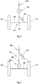
- At least one transverse beam 146 may be operatively connected between the two front wheels 114 and the steering assembly 142 as can be seen in Figure 4 , or alternatively it can be connected otherwise as can be seen in Figure 5 .
- the steering assembly 142 is tiltably connected relative to the transverse beam 146 with a bearing 150 to enable tilting of the vehicle.
- At least one variable damper 148 can be transversely disposed between one end of the at least one transverse beam 146 and any one of the tilting frame (not shown), the suspension assembly 140 and the steering assembly 142, for example.
- Two transversely disposed variable subdampers may for example be provided in a push-pull relationship and have adjacent facing ends articulated to one end of the transverse beam 146 and opposite ends articulated to opposite ends of any one of the tilting frame (not shown), the suspension assembly 140 or the steering assembly 142. The two subdampers act as one damper.
- At least one of the variable dampers may, for example, be a double-acting hydraulic damper fluidly interconnected between both sides of the piston by a closed loop hydraulic circuit.
- the closed loop hydraulic circuit includes, for example, two two-way solenoid valves fluidly connected between the two double-acting hydraulic dampers, and a reservoir fluidly connected between the two two-way solenoid valves.
- the closed loop hydraulic circuit includes, for example, an electro-rheologic fluid or a magneto-rheologic fluid and at least one electro rheologic valve or one magneto rheologic valve hydraulically connected between both sides of at least one damper piston.
- the controller (not shown) is configured to control bi-directional fluid flow through the two two-way solenoid valves or the electro rheologic valve or one magneto rheologic valve to thereby vary transverse damping by at least one double-acting hydraulic damper.
- the at least one sensor is selected from, for example, a tilt sensor, a tilt speed sensor, a vehicle speed sensor, a steering angle sensor, a steering angle velocity sensor, a steering angle acceleration sensor, a side wind sensor and combinations thereof.
- the controller gives higher priority to the signal from the steering angle velocity sensor or the steering angle acceleration sensor than any other sensor.
- the suspension assembly 140 may, for example, comprise at least one shock absorber (not shown) having a closed loop hydraulic circuit which includes, for example, a electro-rheologic fluid or a magneto-rheologic fluid and at least one electro rheologic valve or one magneto rheologic valve hydraulically connected between both sides of a piston of the at least one damper or a mechanical lock out device (not shown).
- the vehicle includes at least one steering damper.
- the steering damper may be mounted within the steering assembly, for example.
- the steering damper of the vehicle, or a vehicle with only two wheels with at least one steering damper mounted between the steering wheel or handlebar and the frame has a closed loop hydraulic circuit which includes a electro-rheologic fluid or a magneto-rheologic fluid and at least one electro rheologic valve or one magneto rheologic valve hydraulically connected between both sides of the at least one damper.
- the controller (not shown) may be configured to control bi-directional fluid flow through the steering damper by controlling the position of the electro-rheologic valve or one magneto-rheologic valve to thereby vary steering damping by at least one double-acting hydraulic damper.
- the rear wheel is driven by a motor. In other embodiments, the rear wheel can be steered to simplify the tilting mechanism of the vehicle.
- the steering assembly includes a steering stem which is backwardly inclined so that an upper end of the steering stem is disposed towards the front of the vehicle.
- a mechanical tilting lockout (not shown) may be provided to prevent tilting of the frame during parking.
- the mechanical tilting lockout may, for example, by activated by a solenoid.
- the controller is connected to the brake system (not shown) of the vehicle and to vary brake pressure by opening a by-pass valve in the brake system or by increasing the brake pressure with an active pump.
- the controller (not shown) is connected to a powertrain control system of the vehicle to vary power and torque output from the power train to the wheels of the vehicle.
- the vehicle can have at least two different powertrains connected to at least two different wheels and that the torque of each of these powertrains can be controlled independently from each other.
- the controller (not shown) is a fuzzy controller that executes a fuzzy logic algorithm. In some embodiments the controller uses look-up tables to control the position of the or each damper.
- variable damper provides, for example, a continuously variable damping force in both directions of movement at zero velocity of the damper with a spread of at least 10 in a range between a maximum force of 1000N or higher and a minimum force of 100N or lower, or in case of a rotational damper a maximum torque of at least 70Nm or more and a minimum torque of 7Nm or less.
- the tilting vehicle includes a frame freely tiltable transversely between at least two longitudinally spaced wheels.
- the vehicle includes at least one variable damper with adjustable damping force operatively connected between the frame and the at least two wheels, at least one sensor to generate signals indicative of transverse tilting of the frame relative to a central vertical plane of the vehicle, and a controller in communication with the at least one variable damper and the at least one sensor.
- the controller is configured to vary transverse damping by the at least one variable damper in accordance with the signals generated by the at least one sensor to passively provide transverse tilt stability to the frame through the force generated in the damper in the opposite direction of the damper movement.
- the vehicle can further include at least one steering damper, the steering damper having a closed loop hydraulic circuit which includes a electro-rheologic fluid or a magneto-rheologic fluid and at least one electro rheologic valve or one magneto rheologic valve hydraulically connected between both sides of the at least one damper.
- the steering damper having a closed loop hydraulic circuit which includes a electro-rheologic fluid or a magneto-rheologic fluid and at least one electro rheologic valve or one magneto rheologic valve hydraulically connected between both sides of the at least one damper.
- Embodiments of the invention passively provide tilting vehicles with transverse tilt stability, and thereby obviate the necessity of complicated and expensive active tilt control systems.
- the at least one damper may be electrical or pneumatic.
- the at least one damper may also be rotational.
Landscapes
- Engineering & Computer Science (AREA)
- Mechanical Engineering (AREA)
- Vehicle Body Suspensions (AREA)
- Automatic Cycles, And Cycles In General (AREA)
Description
- The present invention relates to tilt control for tilting vehicles.
- Tilting vehicles are subject to overturning transversely due to transverse forces such as side wind forces, transverse gravitational force components, and centrifugal forces. Active tilt control systems have been proposed to prevent transverse overturning. Such systems generally include transverse actuators to force the vehicle to tilt transversely to counteract transverse forces on the vehicle. Some existing solutions comprise a mechanical brake being in a brake state or open state, a manually operated tilt control. The solution usually is just a plausibility check that doesn't comprise any sensors to measure tilt angle or tilt rate and it can be activated either manually or by using a plausibility check, for example in case of an acceleration of the vehicle. Active tilt control systems are complicated and expensive.
-
WO 02/068228 A1 - In
WO 2006/130007 A2 a similar tilting vehicle is described wherein a side wind sensor applied for correcting a control or applying pressure to tilting elements for reaming a vehicle in an upright position. - What is needed is a solution which addresses the above difficulties.
- According to a first aspect of the present invention, there is provided a tilting vehicle including a frame freely tiltable transversely between at least two spaced wheels, at least one variable damper with adjustable damping force operatively connected between the frame and the two wheels, at least one sensor to generate signals indicative of transverse tilting of the frame relative to a central vertical plane of the vehicle, and a controller in communication with the at least one variable damper and the at least one sensor, wherein the controller is configured to vary transverse damping by the at least one variable damper in accordance with the signals generated by the at least one sensor to passively provide transverse tilt stability to the frame through the force generated in the damper in the opposite direction of the damper movement. The invention suggests to transversely damp a freely tiltable frame in accordance to a damping state for enhancing driving security and comfort of the vehicle. The anti-tilting apparatus solely comprises at least one damper, at least one sensor and a controller for controlling the damper in accordance to the sensed tilting state of the vehicle. The anti-tilting apparatus is cheap, easy to use and can be refitted to existing vehicles. In contrast to known solutions the anti-tilting apparatus does not rely on a mechanical brake or an actively operated hydraulic system using actuators such as an electro motor, oil pump, hydraulic pressure reservoir or similar. The system is automatically controlled by a controller on response of a tilting state sensed by a tilting sensor, which can be a tilt-angle sensor, a tilt-velocity or a tilt-acceleration sensor. The system is energy efficient, operates in a semi-passive mode without additional power demand for driving actuators, whereby an active change of the tilting state can be powered by the operating weight of the vehicle and the driver. Only a slight operating electric power is needed for operating the controller and some switching elements such as hydraulic or pneumatic valves. The operating power can be provided by a small battery or accumulator, thus the system can be applied to a motorized as well as a non-motorized vehicle such as a bicycle or similar.
- The at least one sensor comprises at least a side wind sensor for detecting a side wind which forces a lateral inclination of the vehicle.
- According to the invention the controller is connected to a brake system of the vehicle to vary brake pressure by opening a by-pass valve in the brake system or by increasing the brake pressure with an active pump. In this way the controller can control tilting as well as breaking for increasing driving safety of the vehicle, for example in case one or more wheels wheel start losing traction.
- Alternatively to a brake system connection or additionally thereto and also according to the invention the controller is connected to a powertrain control system of the vehicle to vary power and torque output from the power train to the wheels of the vehicle. The vehicle can have at least two different powertrains connected to at least two different wheels and that the torque of each of these powertrains can be controlled independently from each other. In this way the controller can control tilting as well as wheel torque for increasing driving safety of the vehicle.
- In an advantageous embodiment the one sensor can further comprise one of a tilt sensor, a tilt speed sensor, a vehicle speed sensor, a steering angle sensor, a steering angle velocity sensor, a steering angle acceleration sensor, or combinations thereof. The controller can give higher priority to the signal from the steering angle velocity sensor or the steering angle acceleration sensor than any other sensor. In this way the controller can consider signals of various sensors hierarchically, whereby signals of the steering angle velocity sensor as being crucial for driving safety have the highest priority.
- According to a favourable embodiment the two wheels can be transversely or longitudinally spaced from each other. In case of transversely spaced wheels the damper can ensure transverse stability against tilting while driving the vehicle or in a parking state. The two transversely spaced wheels define a horizontal axis being parallel to a road and define a reference axis for measuring of and counteracting against a tilting movement. In case of longitudinally spaced wheels the damper can counteract against longitudinal tilting as well as transversal tilting preferably in a steering state, for instance while driving a curve.
- The vehicle can have at least three wheels, wherein the two wheels can be two front wheels longitudinally spaced from at least one rear wheel. The vehicle can be a Trike or a Three-wheeler, favourably a kind of three-wheeled motorcycle, electrobicycle, man-powered bicycle or similar vehicle.
- The vehicle can further include a steering assembly disposed between the frame and the two front wheels. The vehicle can further include a suspension assembly disposed between the steering assembly and the two front wheels. The vehicle can further include a transverse tilt linkage disposed between the steering assembly and the suspension assembly or between the suspension assembly and the two front wheels. The two front wheels can change their longitudinal alignment with respect to the vehicle's longitudinal axis for controlling the direction of movement. A suspension assembly can increase comfort and can reduce mechanical shocks to the vehicle's frame. A transverse tilt linkage can increase stability and rating of the vehicle's frame.
- The steering assembly can be tiltably mounted relative to the at least one transverse beam to enable tilting of the vehicle. Thus the vehicle remains comfortably steerable in a tilted position. The at least one transverse beam can be operatively connected between the two front wheels and the steering assembly. Such a connection increases connection reliability between steering assembly and front wheels especially in rough driving conditions.
- Alternatively, the suspension assembly can be disposed between the frame and the steering assembly. A transverse tilt linkage can be disposed between the frame and the suspension assembly or between the steering assembly and the suspension assembly. In this way the suspension assembly is in series connection with the transverse tilt linkage and can act additive to the function of the transverse tilt linkage.
- The at least one variable damper can be transversely disposed between one end of the at least one transverse beam and any one of the frame, the suspension assembly and the steering assembly. In this way a relative movement of frame and transverse beam is defined through the damper movement and a mechanical variable linkage between frame and transverse beam is installed. The at least one variable damper can comprise two transversely disposed variable subdampers in a push-pull relationship. The two variable subdampers can have adjacent facing ends articulated to one end of the transverse beam and opposite ends articulated to opposite ends of any one of the frame, the suspension assembly or the steering assembly. Thus a damper relies on two counteracting subdampers which provides redundancy and enhances damping effects and operating range the damper.
- Alternatively, the transverse tilt linkage can include upper and lower transverse beams articulated together by a central link, which decreases stiffness of the linkage. The central link can form part of the frame or part of the steering assembly and the link can be connected to a generally central portion of each transverse beam. The suspension assembly can include two transversely spaced suspension struts disposed between the upper and lower transverse beam and the two front wheels, which can reduce damping forces of each suspension strut. The at least one variable damper can be transversely disposed between one end of at least one transverse beam and the central link. The at least one damper can comprise two transversely disposed variable subdampers in a push-pull relationship. The two variable dampers can have adjacent facing ends articulated to the central link and opposite ends articulated to opposite ends of the transverse beam, thus increasing damping effects and reliability of the suspension assembly.
- At least one of the two variable dampers can be hydraulically or electrically operated, thus being controllable by a hydraulic or electric controlling system. At least one of the two variable dampers can be a double-acting hydraulic damper fluidly interconnected between both sides of the damper by a closed loop hydraulic circuit, A closed loop hydraulic circuit whereby a double-acting damper is passively driven by hydraulic fluid pressurized in a corresponding chamber of the same damper or another damper features a passive tilting system without actively operated devices as an oil pump thus reducing costs and complex actively operated actuators. The closed loop hydraulic circuit can include two two-way solenoid valves fluidly connected between the at least one double-acting hydraulic damper, and a reservoir fluidly connected between the two two-way solenoid valves. The two valves can easily be controlled, whereby in a failsafe-position the valves can stay open. The controller can be configured to control bi-directional fluid flow through the hydraulic circuit such that the passive damping forces of the damper is actively controllable by the controller
- The closed loop hydraulic circuit can include an electro-rheologic fluid or a magneto-rheologic fluid and at least one electro rheologic valve or at least one magneto rheologic valve hydraulically connected between both sides of the at least one damper. By controlling the rheologic characteristics of the fluid, like the viscosity, the damping characteristics can be controlled or adjusted by an electric or magnetic field thus reducing mechanical parts and increasing reliability and response time of the suspension assembly.
- The suspension assembly can comprise at least one shock absorber having a closed loop hydraulic circuit which includes a electro-rheologic fluid or a magneto-rheologic fluid and at least one electro rheologic valve or one magneto rheologic valve hydraulically connected between both sides of a piston of the at least one damper or a mechanical lock out device. By controlling the rheologic characteristics of the fluid, like the viscosity, the shock absorber characteristics can be controlled or adjusted by an electric or magnetic field thus reducing mechanical parts and increasing reliability and response time of the suspension assembly.
- The vehicle can include at least one steering damper. The steering damper can be mounted within the steering assembly. The steering damper can reduce effects of sudden steering movements of the driver thus smoothing driving behaviour and increases driving safety.
- The vehicle, preferably a vehicle with only two wheels can have at least one steering damper mounted between the steering wheel or handlebar and the frame, wherein the steering damper has a closed loop hydraulic circuit which includes a electro-rheologic fluid or a magneto-rheologic fluid and at least one electro rheologic valve or one magneto rheologic valve hydraulically connected between both sides of the at least one damper.
- The controller can be configured to control bi-directional fluid flow through the at least one steering damper by controlling the position of the electro-rheologic valve or one magneto-rheologic valve to thereby vary steering damping. Thus an extension and retraction of a damper can be controlled actively by an electric or magnetic field which can be powered by the vehicle's board electric system.
- The rear wheel can be driven by a motor. The rear wheel can be steered. Driving a rear wheel can improve traction and driving dynamic of the vehicle. A steerable rear wheel can improve steering capability of the vehicle. Driving one rear wheel is cheaper and less complex than driving two front wheels, whereby a vehicle having two transversely spaced front wheels and at least one rear wheel is an advantageous embodiment of the invention.
- The steering assembly can include a steering stem which is backwardly inclined so that an upper end of the steering stem is disposed towards the front of the vehicle. During a tilt operation an inclined steering stem reduces tilt of the steering assembly such that tilt effects are reduced.
- A solenoid activated mechanical tilting lockout can be provided to prevent tilting of the frame during parking. A fixation of the tiltable frame during parking can increase anti-theft security and can prevent damage of the vehicle. A mechanical lockout provides further redundancy in case the hydraulic system would leak after a long period without use, for example through biting attacks from animals.
- The controller can be a fuzzy controller that executes a fuzzy logic algorithm. The controller can use look-up tables to control the position of the or each damper. By using fuzzy logic and/or look up tables the controller can control the tilting state of the vehicle in an intelligent way and can optimize tilting behaviour in different driving situations, for instance when driving with low or high velocity, driving upward or downward. The controller can consider weather and road conditions like wet streets, winding roads or similar and can control more intelligent.
- The at least one variable damper can provide a continuously variable damping force in both directions of movement at zero velocity of the damper with a spread of at least 10 in a range between a maximum force of 1000N and a minimum force of 100N, or in case of a rotational damper a maximum torque of at least 70Nm and a minimum torque of 7Nm. Such a variable damping force can adapt reaction of the damping system to certain parameters as tilting angle and driving condition, whereby a force being optimal to a distinct driving state can be chosen.
- The invention will be further described by way of example only with reference to the accompanying drawings, in which:
- Figure 1
- is a schematic of a tilting vehicle of an embodiment of the invention;
- Figure 2
- is a schematic diagram of a tilt linkage of the vehicle;
- Figure 3
- is a hydraulic circuit diagram of a passive tilt control system of the vehicle;
- Figure 4
- is a schematic diagram of an alternative tilt linkage; and
- Figure 5
- is a schematic diagram of another alternative tilt linkage.
-
Figure 1 illustrates a tiltingvehicle 10 of one embodiment of the invention. Thevehicle 10 has aframe 12 manually or freely tiltable transversely between two transversely spacedfront wheels 14. Thevehicle 10 also has a motor-driven rear wheel not visible inFigure 1 . The twofront wheels 14 are steerable by ahandlebar 16 connected to a steering assembly (not visible inFigure 1 ) disposed between theframe 12 and the twofront wheels 14. Thevehicle 10 also has a suspension assembly including two transversely spaced suspension struts 18 (one of which is visible inFigure 1 ) disposed between the steering assembly and the twofront wheels 14. - A
transverse tilt linkage 20 is disposed between the steering assembly and the suspension assembly. Referring toFigure 2 , thetransverse tilt linkage 20 includes upper and lowertransverse beams central link 26. Two double-actinghydraulic dampers transverse beams dampers central link 26 and opposite cap ends articulated to opposite ends of the uppertransverse beam 22. Referring again toFigure 1 , the suspension struts 18 are vertically disposed between the lowertransverse beam 24 and the twofront wheels 14. - The two double-acting
hydraulic dampers hydraulic circuit 32 illustrated inFigure 3 . The closed loophydraulic circuit 32 includes two two-way solenoid valves hydraulic dampers reservoir 38 fluidly connected between the two two-way solenoid valves - A controller (not shown) is provided in communication with the two two-
way solenoid valves frame 12. The sensors include, for example, a tilt sensor, a vehicle speed sensor, and a steering angle sensor. The controller is configured to control bi-directional fluid flow through the two two-way solenoid valves hydraulic dampers frame 12. The controller is, for example, a fuzzy controller that executes a fuzzy logic algorithm. The fuzzy logic algorithm is, for example, based on calculated and/or measured dynamic transverse tilting characteristics of thevehicle 10. - In other embodiments (not shown), the suspension assembly is disposed between the frame and the steering assembly. According to these embodiments, a transverse tilt linkage is disposed between the frame and the suspension assembly or between the steering assembly and the suspension assembly for example.
- With reference to
Figures 4 and 5 , other embodiments of the vehicle include atilt linkage 144 disposed between the front wheels and the steering assembly. At least onetransverse beam 146 may be operatively connected between the twofront wheels 114 and thesteering assembly 142 as can be seen inFigure 4 , or alternatively it can be connected otherwise as can be seen inFigure 5 . Thesteering assembly 142 is tiltably connected relative to thetransverse beam 146 with abearing 150 to enable tilting of the vehicle. - At least one
variable damper 148 can be transversely disposed between one end of the at least onetransverse beam 146 and any one of the tilting frame (not shown), thesuspension assembly 140 and thesteering assembly 142, for example. Two transversely disposed variable subdampers (not shown), may for example be provided in a push-pull relationship and have adjacent facing ends articulated to one end of thetransverse beam 146 and opposite ends articulated to opposite ends of any one of the tilting frame (not shown), thesuspension assembly 140 or thesteering assembly 142. The two subdampers act as one damper. - At least one of the variable dampers may, for example, be a double-acting hydraulic damper fluidly interconnected between both sides of the piston by a closed loop hydraulic circuit. The closed loop hydraulic circuit includes, for example, two two-way solenoid valves fluidly connected between the two double-acting hydraulic dampers, and a reservoir fluidly connected between the two two-way solenoid valves. The closed loop hydraulic circuit includes, for example, an electro-rheologic fluid or a magneto-rheologic fluid and at least one electro rheologic valve or one magneto rheologic valve hydraulically connected between both sides of at least one damper piston.
- The controller (not shown) is configured to control bi-directional fluid flow through the two two-way solenoid valves or the electro rheologic valve or one magneto rheologic valve to thereby vary transverse damping by at least one double-acting hydraulic damper.
- The at least one sensor (not shown) is selected from, for example, a tilt sensor, a tilt speed sensor, a vehicle speed sensor, a steering angle sensor, a steering angle velocity sensor, a steering angle acceleration sensor, a side wind sensor and combinations thereof.
- In some embodiments, the controller gives higher priority to the signal from the steering angle velocity sensor or the steering angle acceleration sensor than any other sensor.
- The
suspension assembly 140 may, for example, comprise at least one shock absorber (not shown) having a closed loop hydraulic circuit which includes, for example, a electro-rheologic fluid or a magneto-rheologic fluid and at least one electro rheologic valve or one magneto rheologic valve hydraulically connected between both sides of a piston of the at least one damper or a mechanical lock out device (not shown). - In some embodiments, the vehicle includes at least one steering damper. The steering damper may be mounted within the steering assembly, for example. In some embodiments, the steering damper of the vehicle, or a vehicle with only two wheels with at least one steering damper mounted between the steering wheel or handlebar and the frame, has a closed loop hydraulic circuit which includes a electro-rheologic fluid or a magneto-rheologic fluid and at least one electro rheologic valve or one magneto rheologic valve hydraulically connected between both sides of the at least one damper.
- In some embodiments, the controller (not shown) may be configured to control bi-directional fluid flow through the steering damper by controlling the position of the electro-rheologic valve or one magneto-rheologic valve to thereby vary steering damping by at least one double-acting hydraulic damper.
- In some embodiments, the rear wheel is driven by a motor. In other embodiments, the rear wheel can be steered to simplify the tilting mechanism of the vehicle.
- In some embodiments, the steering assembly includes a steering stem which is backwardly inclined so that an upper end of the steering stem is disposed towards the front of the vehicle.
- In some embodiments, a mechanical tilting lockout (not shown) may be provided to prevent tilting of the frame during parking. The mechanical tilting lockout may, for example, by activated by a solenoid.
- In some embodiments, the controller is connected to the brake system (not shown) of the vehicle and to vary brake pressure by opening a by-pass valve in the brake system or by increasing the brake pressure with an active pump.
- In some embodiments, the controller (not shown) is connected to a powertrain control system of the vehicle to vary power and torque output from the power train to the wheels of the vehicle. The vehicle can have at least two different powertrains connected to at least two different wheels and that the torque of each of these powertrains can be controlled independently from each other.
- In some embodiments, the controller (not shown) is a fuzzy controller that executes a fuzzy logic algorithm. In some embodiments the controller uses look-up tables to control the position of the or each damper.
- In other embodiments, the variable damper provides, for example, a continuously variable damping force in both directions of movement at zero velocity of the damper with a spread of at least 10 in a range between a maximum force of 1000N or higher and a minimum force of 100N or lower, or in case of a rotational damper a maximum torque of at least 70Nm or more and a minimum torque of 7Nm or less.
- In other embodiments, the tilting vehicle includes a frame freely tiltable transversely between at least two longitudinally spaced wheels. The vehicle includes at least one variable damper with adjustable damping force operatively connected between the frame and the at least two wheels, at least one sensor to generate signals indicative of transverse tilting of the frame relative to a central vertical plane of the vehicle, and a controller in communication with the at least one variable damper and the at least one sensor. The controller is configured to vary transverse damping by the at least one variable damper in accordance with the signals generated by the at least one sensor to passively provide transverse tilt stability to the frame through the force generated in the damper in the opposite direction of the damper movement.
- In this embodiment, the vehicle can further include at least one steering damper, the steering damper having a closed loop hydraulic circuit which includes a electro-rheologic fluid or a magneto-rheologic fluid and at least one electro rheologic valve or one magneto rheologic valve hydraulically connected between both sides of the at least one damper.
- Embodiments of the invention passively provide tilting vehicles with transverse tilt stability, and thereby obviate the necessity of complicated and expensive active tilt control systems.
- The embodiments have been described by way of example only and modifications are possible within the scope of the claims which follow. For example, the at least one damper may be electrical or pneumatic. The at least one damper may also be rotational.
Claims (15)
- A tilting vehicle (10) including a frame (12) freely tiltable transversely between at least two spaced wheels (14, 114), at least one variable damper (28, 30, 148) with adjustable damping force operatively connected between the frame (12) and the two wheels (14, 114), at least one sensor to generate signals indicative of transverse tilting of the frame (12) relative to a central vertical plane of the vehicle, and a controller in communication with the at least one variable damper (28, 30, 148) and the at least one sensor, wherein the controller is configured to vary transverse damping by the at least one variable damper (28, 30, 148) in accordance with the signals generated by the at least one sensor to passively provide transverse tilt stability to the frame (12) through the force generated in the damper in the opposite direction of the damper movement, characterized by the at least one sensor is a side wind sensor for generating signals indicative of transverse tilting of the frame and the controller is connected to a brake system of the vehicle to vary brake pressure by opening a by-pass valve in the brake system or by increasing the brake pressure with an active pump and/or the controller is connected to a powertrain control system of the vehicle to vary power and torque output from the power train to the wheels of the vehicle (10).
- A tilting vehicle (10) according to claim 1 characterized by said sensor comprises furthermore a steering angle velocity sensor and/or a steering angle acceleration sensor
- A tilting vehicle (10) according to claim 1 or claim 2 characterized by said sensor comprises furthermore a tilt sensor, a tilt speed sensor, a vehicle speed sensor, a steering angle sensor or a combination thereof.
- A vehicle according to one of the foregoing claims, characterized by the two wheels (14, 114) being transversely or longitudinally spaced from each other.
- A vehicle according to any one of claims 1 to 3, characterized by the vehicle (10) has at least three wheels in form of a trike/three-wheeler, or the two transversely spaced wheels are two front wheels (14, 114) longitudinally spaced from at least one rear wheel, and whereby preferably a steering assembly (142) is disposed between the frame (12) and the two front wheels (14, 114), and whereby preferably a suspension assembly (140) is disposed between the steering assembly (142) and the two front wheels (14, 114), whereby preferably a transverse tilt linkage (20) is disposed between the steering assembly (142) and the suspension assembly (140) or between the suspension assembly (140) and the two front wheels (14, 114), and whereby preferably the steering assembly (142) is tiltably mounted relative to at least one transverse beam (22, 24, 146) to enable tilting of the vehicle (10) and whereby preferably the at least one transverse beam (22, 24, 146) is operatively connected between the two front wheels (14, 114) and the steering assembly (142).
- A vehicle according to claim 5, characterized by further including a suspension assembly (140) disposed between the frame (12) and the steering assembly (142).
- A vehicle according to claim 6, characterized by further including a transverse tilt linkage (20) disposed between the frame (12) and the suspension assembly (140) or between the steering assembly (142) and the suspension assembly (140).
- A vehicle according to claim 5 or claim 7, characterized by the at least one variable damper (28, 30, 148) is transversely disposed between one end of the at least one transverse beam (22, 24, 146) and any one of the frame (12), the suspension assembly (140) and the steering assembly (142), whereby preferably the at least one variable damper (28, 30, 148) comprises two transversely disposed variable subdampers in a push-pull relationship, whereby preferably the two variable subdampers have adjacent facing ends articulated to one end of the transverse beam (22, 24, 146) and opposite ends articulated to opposite ends of any one of the frame (12), the suspension assembly (140) or the steering assembly (142).
- A vehicle according to claim 5 or claim 6, characterized by the transverse tilt linkage (20) includes upper and lower transverse beams (22, 24) articulated together by a central link (26), whereby preferably the central link (26) forms part of the frame (12) or part of the steering assembly (142) and the link is connected to a generally central portion of each transverse beam (22, 24), and whereby preferably the suspension assembly (140) includes two transversely spaced suspension struts (18) disposed between the upper and lower transverse beam (22, 24) and the two front wheels (14, 114).
- A vehicle according to claim 9, characterized by the at least one variable damper (28, 30, 148) is transversely disposed between one end of at least one transverse beam (22, 24) and the central link (26), and whereby the at least one variable damper (28, 30, 148) comprises two transversely disposed variable subdampers in a push-pull relationship, and whereby the two variable subdampers have adjacent facing ends articulated to the central link (26) and opposite ends articulated to opposite ends of the transverse beam (22, 24).
- A vehicle according to claim 8 or 10, characterized by at least one of the two variable subdampers is hydraulically or electrically operated, and whereby preferably at least one of the two variable subdampers is a double-acting hydraulic damper fluidly interconnected between both sides of the damper by a closed loop hydraulic circuit.
- A vehicle according to claim 11, characterized by a closed loop hydraulic circuit (32) includes two two-way solenoid valves (34, 36) fluidly connected between the at least one double-acting hydraulic damper (28, 30, 148), and a reservoir fluidly connected between the two two-way solenoid valves (34, 36)., whereby preferably the controller is configured to control bi-directional fluid flow through the hydraulic circuit (32), and whereby preferably the closed loop hydraulic (32) circuit includes an electro-rheologic fluid or a magneto-rheologic fluid and at least one electro rheologic valve or at least one magneto rheologic valve hydraulically connected between both sides of the at least one damper (28, 30, 148).
- A vehicle according to claim 2 and claim 3, characterized by the controller gives higher priority to the signal from the steering angle velocity sensor or the steering angle acceleration sensor than any other sensor.
- A vehicle according to any one of claims 6 to 13, characterized by the suspension assembly (140) comprises at least one shock absorber having a closed loop hydraulic circuit (32) which includes an electro-rheologic fluid or a magneto-rheologic fluid and at least one electro rheologic valve or one magneto rheologic valve hydraulically connected between both sides of a piston of the at least one damper (28, 30, 148) or a mechanical lock out device.
- A vehicle according to any of the preceding claims, characterized by further including at least one steering damper, whereby in a vehicle with only two wheels preferably at least one steering damper is mounted between the steering wheel (14, 114) or handlebar (16) and the frame (12), and the steering damper has preferably a closed loop hydraulic circuit (32) which includes a electro-rheologic fluid or a magneto-rheologic fluid and at least one electro rheologic valve or one magneto rheologic valve hydraulically connected between both sides of the at least one steering damper, whereby preferably the controller is configured to control bi-directional fluid flow through the at least one steering damper by controlling the position of the electro-rheologic valve or one magneto-rheologic valve to thereby vary steering damping.
Priority Applications (1)
| Application Number | Priority Date | Filing Date | Title |
|---|---|---|---|
| EP16203311.2A EP3192730B1 (en) | 2009-09-08 | 2010-09-06 | Tilt control for tilting vehicles |
Applications Claiming Priority (2)
| Application Number | Priority Date | Filing Date | Title |
|---|---|---|---|
| AU2009904277A AU2009904277A0 (en) | 2009-09-08 | Tilt control for tilting vehicles | |
| EP10754711.9A EP2475570B1 (en) | 2009-09-08 | 2010-09-06 | Tilt control for tilting vehicles |
Related Parent Applications (2)
| Application Number | Title | Priority Date | Filing Date |
|---|---|---|---|
| EP10754711.9A Division EP2475570B1 (en) | 2009-09-08 | 2010-09-06 | Tilt control for tilting vehicles |
| EP10754711.9 Division | 2010-09-06 |
Related Child Applications (2)
| Application Number | Title | Priority Date | Filing Date |
|---|---|---|---|
| EP16203311.2A Division-Into EP3192730B1 (en) | 2009-09-08 | 2010-09-06 | Tilt control for tilting vehicles |
| EP16203311.2A Division EP3192730B1 (en) | 2009-09-08 | 2010-09-06 | Tilt control for tilting vehicles |
Publications (3)
| Publication Number | Publication Date |
|---|---|
| EP2628672A2 EP2628672A2 (en) | 2013-08-21 |
| EP2628672A3 EP2628672A3 (en) | 2015-11-11 |
| EP2628672B1 true EP2628672B1 (en) | 2017-04-19 |
Family
ID=43244858
Family Applications (3)
| Application Number | Title | Priority Date | Filing Date |
|---|---|---|---|
| EP10754711.9A Active EP2475570B1 (en) | 2009-09-08 | 2010-09-06 | Tilt control for tilting vehicles |
| EP16203311.2A Active EP3192730B1 (en) | 2009-09-08 | 2010-09-06 | Tilt control for tilting vehicles |
| EP13168191.8A Active EP2628672B1 (en) | 2009-09-08 | 2010-09-06 | Tilt control for tilting vehicles |
Family Applications Before (2)
| Application Number | Title | Priority Date | Filing Date |
|---|---|---|---|
| EP10754711.9A Active EP2475570B1 (en) | 2009-09-08 | 2010-09-06 | Tilt control for tilting vehicles |
| EP16203311.2A Active EP3192730B1 (en) | 2009-09-08 | 2010-09-06 | Tilt control for tilting vehicles |
Country Status (3)
| Country | Link |
|---|---|
| EP (3) | EP2475570B1 (en) |
| CN (1) | CN102596697B (en) |
| WO (1) | WO2011029795A1 (en) |
Families Citing this family (37)
| Publication number | Priority date | Publication date | Assignee | Title |
|---|---|---|---|---|
| KR101365709B1 (en) * | 2013-08-29 | 2014-02-20 | 김성진 | Apparatus and method for controlling rolling of vehicles |
| KR101470221B1 (en) * | 2013-10-17 | 2014-12-05 | 현대자동차주식회사 | Apparatus for controlling suspension and method thereof |
| US9428236B2 (en) * | 2013-11-06 | 2016-08-30 | Bryan Goss | Lean-compensating motorcycle with channel wheels |
| JP6063861B2 (en) * | 2013-12-27 | 2017-01-18 | 本田技研工業株式会社 | Swing control system for swinging vehicle |
| JP6006714B2 (en) * | 2013-12-27 | 2016-10-12 | 本田技研工業株式会社 | Swing control system for swinging vehicle |
| DE102014209328A1 (en) | 2014-05-16 | 2015-11-19 | Ford Global Technologies, Llc | Wheel suspension for a tilting suspension and taillight, as well as procedures for its operation and suitably equipped vehicle |
| DE202014102328U1 (en) | 2014-05-16 | 2014-06-10 | Ford Global Technologies, Llc | Suspension for a tilting suspension and tilting suspension |
| DE102014209329A1 (en) | 2014-05-16 | 2015-11-19 | Ford Global Technologies, Llc | Wheel suspension for a tilting suspension and taillight, as well as procedures for its operation and suitably equipped vehicle |
| CA2952358A1 (en) * | 2014-06-20 | 2015-12-23 | Quadro Vehicles Sa | Improved control system of the trim of vehicles with more than two wheels |
| DE102014217246B3 (en) * | 2014-08-29 | 2015-12-24 | Ford Global Technologies, Llc | Stabilization arrangement for a tilting chassis of a vehicle |
| DE202014104070U1 (en) | 2014-08-29 | 2014-09-09 | Ford Global Technologies, Llc | Stabilization arrangement for a tilting chassis of a vehicle and tilting chassis |
| DE102014217247A1 (en) | 2014-08-29 | 2016-03-03 | Ford Global Technologies, Llc | Stabilization arrangement for a tilting chassis of a vehicle and tilting chassis |
| DE102014217386A1 (en) | 2014-09-01 | 2016-03-03 | Ford Global Technologies, Llc | Method for operating a tilting chassis and active tilting suspension for a rail-bound vehicle |
| US10076939B2 (en) | 2014-11-26 | 2018-09-18 | Ford Global Technologies, Llc | Suspension systems for laterally tiltable multitrack vehicles |
| US9925843B2 (en) | 2015-02-24 | 2018-03-27 | Ford Global Technologies, Llc | Rear suspension systems for laterally tiltable multitrack vehicles |
| US10023019B2 (en) | 2015-02-24 | 2018-07-17 | Ford Global Technologies, Llc | Rear suspension systems with rotary devices for laterally tiltable multitrack vehicles |
| EP3378748B1 (en) | 2015-11-20 | 2023-08-09 | Yamaha Hatsudoki Kabushiki Kaisha | Leaning vehicle |
| EP3378749B1 (en) | 2015-11-20 | 2020-04-01 | Yamaha Hatsudoki Kabushiki Kaisha | Leaning vehicle |
| WO2017086403A1 (en) | 2015-11-20 | 2017-05-26 | ヤマハ発動機株式会社 | Vehicle |
| WO2017086350A1 (en) | 2015-11-20 | 2017-05-26 | ヤマハ発動機株式会社 | Leaning vehicle |
| EP3412530A4 (en) * | 2016-02-04 | 2019-02-13 | Yamaha Hatsudoki Kabushiki Kaisha | Leaning vehicle |
| JP6684898B2 (en) * | 2016-04-18 | 2020-04-22 | ヤマハ発動機株式会社 | Lean vehicle with lean attitude control actuator and left and right inclined wheels |
| CN109562808B (en) * | 2016-08-21 | 2021-07-02 | D.S.瑞德有限公司 | Vehicle with front and/or rear steering mechanism based on lateral horizontal force exerted on the chassis of the vehicle |
| DE102016221838A1 (en) | 2016-11-08 | 2018-05-09 | Schaeffler Technologies AG & Co. KG | Tilting suspension for a motor vehicle |
| IT201600129510A1 (en) | 2016-12-21 | 2018-06-21 | Piaggio & C Spa | ADVANCE OF ROLLANTE MOTORCYCLE WITH ROLLIO CONTROL |
| IT201600129491A1 (en) | 2016-12-21 | 2018-06-21 | Piaggio & C Spa | ADVANCE OF ROLLANTE MOTORCYCLE WITH ROLLO BLOCK |
| IT201600129502A1 (en) | 2016-12-21 | 2018-06-21 | Piaggio & C Spa | ADVANCED ROLLER MOTORCYCLE WITH ROLLI CONTROL |
| CN107487402B (en) * | 2017-07-20 | 2023-04-25 | 庶邦科技(上海)有限公司 | Damping mechanism and mounting structure thereof |
| TWI615311B (en) * | 2017-07-27 | 2018-02-21 | 光陽工業股份有限公司 | Vehicle with anti-tilt locking |
| CN109367668A (en) * | 2017-08-03 | 2019-02-22 | 光阳工业股份有限公司 | Vehicle with Anti-inclining lock function |
| CN109955973B (en) * | 2017-12-26 | 2021-06-11 | 亚帝发工业股份有限公司 | Concrete structure for stabilizing and inclining vertical lathe |
| TWI809203B (en) * | 2018-09-28 | 2023-07-21 | 義大利商比雅久&C公司 | Forecarriage for motor vehicles with two front steered wheels, with a central shock absorber assembly, and motor vehicle comprising said forecarriage |
| US11072389B2 (en) | 2019-02-22 | 2021-07-27 | Sway Motorsports Llc | Three-wheeled tilting vehicle |
| WO2020172685A1 (en) | 2019-02-22 | 2020-08-27 | Sway Motorsports Llc | Three-wheeled tilting vehicle |
| CN111150273B (en) * | 2020-01-08 | 2021-07-30 | 南京溧水高新产业股权投资有限公司 | Anti-collision toppling artwork display stand |
| CN111409749B (en) * | 2020-03-23 | 2021-09-10 | 苏州盱酋汽车科技有限公司 | Tricycle capable of automatically inclining when turning |
| TW202248076A (en) * | 2021-06-10 | 2022-12-16 | 優何 克里博 | Apparatus for providing a restoring moment for a two-wheeled vehicle steering mechanism |
Family Cites Families (11)
| Publication number | Priority date | Publication date | Assignee | Title |
|---|---|---|---|---|
| US4351410A (en) * | 1980-07-17 | 1982-09-28 | Townsend Engineering Company | Self-balancing wheeled vehicle |
| NL1007045C2 (en) * | 1997-09-16 | 1999-03-25 | Brinks Westmaas Bv | Tilting vehicle. |
| GB0029136D0 (en) * | 2000-11-29 | 2001-01-10 | Shotter Nicholas R | Motorcycle-type vehicle |
| ES2266170T3 (en) * | 2001-02-27 | 2007-03-01 | PIAGGIO & C. S.P.A. | THREE-WHEEL VEHICLE WITH TILT SUSPENSION SYSTEM. |
| EP1362779B1 (en) * | 2002-05-17 | 2011-04-20 | The Four Wheeled Motorcycle Company Limited | Motorcycle-type vehicles |
| DE102004054188A1 (en) * | 2004-11-10 | 2006-05-11 | Bayerische Motoren Werke Ag | Motorcycle with steering damper |
| EP1885593B1 (en) * | 2005-05-31 | 2011-07-20 | Brinks Westmaas B.V. | Self-balancing vehicle |
| JP2006341690A (en) * | 2005-06-08 | 2006-12-21 | Rikogaku Shinkokai | Three-wheeled moving vehicle |
| US7460936B2 (en) * | 2006-05-12 | 2008-12-02 | Delphi Technologies, Inc. | System and method for controlling vehicle hydraulic system |
| DE102007020580A1 (en) * | 2007-05-02 | 2008-11-06 | Ktm Sportmotorcycle Ag | control device |
| WO2009059099A2 (en) * | 2007-10-31 | 2009-05-07 | Vectrix Corporation | Lockable tilt system for a three-wheeled vehicle |
-
2010
- 2010-09-06 EP EP10754711.9A patent/EP2475570B1/en active Active
- 2010-09-06 EP EP16203311.2A patent/EP3192730B1/en active Active
- 2010-09-06 EP EP13168191.8A patent/EP2628672B1/en active Active
- 2010-09-06 CN CN201080040011.2A patent/CN102596697B/en not_active Expired - Fee Related
- 2010-09-06 WO PCT/EP2010/063040 patent/WO2011029795A1/en active Application Filing
Non-Patent Citations (1)
| Title |
|---|
| None * |
Also Published As
| Publication number | Publication date |
|---|---|
| CN102596697A (en) | 2012-07-18 |
| EP2628672A3 (en) | 2015-11-11 |
| WO2011029795A1 (en) | 2011-03-17 |
| EP2475570B1 (en) | 2013-07-03 |
| CN102596697B (en) | 2014-12-10 |
| EP2475570A1 (en) | 2012-07-18 |
| EP3192730A1 (en) | 2017-07-19 |
| EP2628672A2 (en) | 2013-08-21 |
| EP3192730B1 (en) | 2020-03-25 |
Similar Documents
| Publication | Publication Date | Title |
|---|---|---|
| EP2628672B1 (en) | Tilt control for tilting vehicles | |
| JP6920371B2 (en) | vehicle | |
| US11161565B2 (en) | Bicycle control device and bicycle electric assist unit including bicycle control device | |
| EP2729351B1 (en) | A vehicle | |
| EP2058155B1 (en) | Suspension device and method during spring action and/or damping action for a vehicle | |
| US8899600B2 (en) | Device for controlling the angle of tilt of a frame mounted on a tiltable wheel set | |
| US9045015B2 (en) | Laterally tiltable, multitrack vehicle | |
| CN101511617B (en) | Stability control system for tree-wheel or four-wheel motorcycle | |
| CN105082921B (en) | The vehicle for the wheel suspension and tilt chassis of tilt chassis and their operating method and being accordingly equipped with | |
| EP0020835A1 (en) | Ultra narrow enclosed motor vehicles | |
| CN106573517B (en) | Motor vehicle | |
| CN108137118B (en) | Vehicle suspension device | |
| CN102490566B (en) | Initiative side-tipping resisting stabilizer bar | |
| EP0788443B1 (en) | Anti-roll-over system for three or four-wheeled motor vehicle and motor vehicle comprising said anti-roll system | |
| JPS6226109A (en) | Suspension system for car | |
| US20120310478A1 (en) | Tilting vehicle and control system thereof | |
| JP2011126405A (en) | Semiactive suspension | |
| ES2829634T3 (en) | Suspension lockout arrangement with front sag reduction for motor vehicles | |
| EP2650193B1 (en) | Rear-suspension system for three-wheeled vehicles | |
| CN109986922A (en) | Roll control method, vehicle and the lateral stability rod driving device of vehicle | |
| CN211995943U (en) | Vehicle fulcrum system and vehicle comprising same | |
| GB2433236A (en) | Motorcycle with a wheelbase variation mechanism | |
| CN207942900U (en) | Vehicle and lateral stability rod driving device | |
| KR101448796B1 (en) | Suspension system for vehicles | |
| KR200161831Y1 (en) | Position control device of vehicle |
Legal Events
| Date | Code | Title | Description |
|---|---|---|---|
| PUAI | Public reference made under article 153(3) epc to a published international application that has entered the european phase |
Free format text: ORIGINAL CODE: 0009012 |
|
| AC | Divisional application: reference to earlier application |
Ref document number: 2475570 Country of ref document: EP Kind code of ref document: P |
|
| AK | Designated contracting states |
Kind code of ref document: A2 Designated state(s): AL AT BE BG CH CY CZ DE DK EE ES FI FR GB GR HR HU IE IS IT LI LT LU LV MC MK MT NL NO PL PT RO SE SI SK SM TR |
|
| PUAL | Search report despatched |
Free format text: ORIGINAL CODE: 0009013 |
|
| AK | Designated contracting states |
Kind code of ref document: A3 Designated state(s): AL AT BE BG CH CY CZ DE DK EE ES FI FR GB GR HR HU IE IS IT LI LT LU LV MC MK MT NL NO PL PT RO SE SI SK SM TR |
|
| RIC1 | Information provided on ipc code assigned before grant |
Ipc: B62K 5/10 20130101AFI20151007BHEP Ipc: B62K 5/05 20130101ALI20151007BHEP Ipc: B62K 5/027 20130101ALI20151007BHEP Ipc: B62K 5/08 20060101ALI20151007BHEP |
|
| 17P | Request for examination filed |
Effective date: 20160511 |
|
| RBV | Designated contracting states (corrected) |
Designated state(s): AL AT BE BG CH CY CZ DE DK EE ES FI FR GB GR HR HU IE IS IT LI LT LU LV MC MK MT NL NO PL PT RO SE SI SK SM TR |
|
| GRAP | Despatch of communication of intention to grant a patent |
Free format text: ORIGINAL CODE: EPIDOSNIGR1 |
|
| INTG | Intention to grant announced |
Effective date: 20160803 |
|
| GRAJ | Information related to disapproval of communication of intention to grant by the applicant or resumption of examination proceedings by the epo deleted |
Free format text: ORIGINAL CODE: EPIDOSDIGR1 |
|
| INTC | Intention to grant announced (deleted) | ||
| GRAP | Despatch of communication of intention to grant a patent |
Free format text: ORIGINAL CODE: EPIDOSNIGR1 |
|
| INTG | Intention to grant announced |
Effective date: 20170209 |
|
| GRAS | Grant fee paid |
Free format text: ORIGINAL CODE: EPIDOSNIGR3 |
|
| GRAA | (expected) grant |
Free format text: ORIGINAL CODE: 0009210 |
|
| AC | Divisional application: reference to earlier application |
Ref document number: 2475570 Country of ref document: EP Kind code of ref document: P |
|
| AK | Designated contracting states |
Kind code of ref document: B1 Designated state(s): AL AT BE BG CH CY CZ DE DK EE ES FI FR GB GR HR HU IE IS IT LI LT LU LV MC MK MT NL NO PL PT RO SE SI SK SM TR |
|
| REG | Reference to a national code |
Ref country code: GB Ref legal event code: FG4D |
|
| REG | Reference to a national code |
Ref country code: CH Ref legal event code: EP |
|
| REG | Reference to a national code |
Ref country code: AT Ref legal event code: REF Ref document number: 885655 Country of ref document: AT Kind code of ref document: T Effective date: 20170515 |
|
| REG | Reference to a national code |
Ref country code: IE Ref legal event code: FG4D |
|
| REG | Reference to a national code |
Ref country code: DE Ref legal event code: R096 Ref document number: 602010041771 Country of ref document: DE |
|
| REG | Reference to a national code |
Ref country code: NL Ref legal event code: MP Effective date: 20170419 |
|
| REG | Reference to a national code |
Ref country code: LT Ref legal event code: MG4D |
|
| REG | Reference to a national code |
Ref country code: AT Ref legal event code: MK05 Ref document number: 885655 Country of ref document: AT Kind code of ref document: T Effective date: 20170419 |
|
| REG | Reference to a national code |
Ref country code: FR Ref legal event code: PLFP Year of fee payment: 8 |
|
| PG25 | Lapsed in a contracting state [announced via postgrant information from national office to epo] |
Ref country code: NL Free format text: LAPSE BECAUSE OF FAILURE TO SUBMIT A TRANSLATION OF THE DESCRIPTION OR TO PAY THE FEE WITHIN THE PRESCRIBED TIME-LIMIT Effective date: 20170419 |
|
| PG25 | Lapsed in a contracting state [announced via postgrant information from national office to epo] |
Ref country code: GR Free format text: LAPSE BECAUSE OF FAILURE TO SUBMIT A TRANSLATION OF THE DESCRIPTION OR TO PAY THE FEE WITHIN THE PRESCRIBED TIME-LIMIT Effective date: 20170720 Ref country code: LT Free format text: LAPSE BECAUSE OF FAILURE TO SUBMIT A TRANSLATION OF THE DESCRIPTION OR TO PAY THE FEE WITHIN THE PRESCRIBED TIME-LIMIT Effective date: 20170419 Ref country code: AT Free format text: LAPSE BECAUSE OF FAILURE TO SUBMIT A TRANSLATION OF THE DESCRIPTION OR TO PAY THE FEE WITHIN THE PRESCRIBED TIME-LIMIT Effective date: 20170419 Ref country code: HR Free format text: LAPSE BECAUSE OF FAILURE TO SUBMIT A TRANSLATION OF THE DESCRIPTION OR TO PAY THE FEE WITHIN THE PRESCRIBED TIME-LIMIT Effective date: 20170419 Ref country code: ES Free format text: LAPSE BECAUSE OF FAILURE TO SUBMIT A TRANSLATION OF THE DESCRIPTION OR TO PAY THE FEE WITHIN THE PRESCRIBED TIME-LIMIT Effective date: 20170419 Ref country code: FI Free format text: LAPSE BECAUSE OF FAILURE TO SUBMIT A TRANSLATION OF THE DESCRIPTION OR TO PAY THE FEE WITHIN THE PRESCRIBED TIME-LIMIT Effective date: 20170419 Ref country code: NO Free format text: LAPSE BECAUSE OF FAILURE TO SUBMIT A TRANSLATION OF THE DESCRIPTION OR TO PAY THE FEE WITHIN THE PRESCRIBED TIME-LIMIT Effective date: 20170719 |
|
| PG25 | Lapsed in a contracting state [announced via postgrant information from national office to epo] |
Ref country code: BG Free format text: LAPSE BECAUSE OF FAILURE TO SUBMIT A TRANSLATION OF THE DESCRIPTION OR TO PAY THE FEE WITHIN THE PRESCRIBED TIME-LIMIT Effective date: 20170719 Ref country code: IS Free format text: LAPSE BECAUSE OF FAILURE TO SUBMIT A TRANSLATION OF THE DESCRIPTION OR TO PAY THE FEE WITHIN THE PRESCRIBED TIME-LIMIT Effective date: 20170819 Ref country code: SE Free format text: LAPSE BECAUSE OF FAILURE TO SUBMIT A TRANSLATION OF THE DESCRIPTION OR TO PAY THE FEE WITHIN THE PRESCRIBED TIME-LIMIT Effective date: 20170419 Ref country code: PL Free format text: LAPSE BECAUSE OF FAILURE TO SUBMIT A TRANSLATION OF THE DESCRIPTION OR TO PAY THE FEE WITHIN THE PRESCRIBED TIME-LIMIT Effective date: 20170419 Ref country code: LV Free format text: LAPSE BECAUSE OF FAILURE TO SUBMIT A TRANSLATION OF THE DESCRIPTION OR TO PAY THE FEE WITHIN THE PRESCRIBED TIME-LIMIT Effective date: 20170419 |
|
| REG | Reference to a national code |
Ref country code: DE Ref legal event code: R097 Ref document number: 602010041771 Country of ref document: DE |
|
| PG25 | Lapsed in a contracting state [announced via postgrant information from national office to epo] |
Ref country code: CZ Free format text: LAPSE BECAUSE OF FAILURE TO SUBMIT A TRANSLATION OF THE DESCRIPTION OR TO PAY THE FEE WITHIN THE PRESCRIBED TIME-LIMIT Effective date: 20170419 Ref country code: SK Free format text: LAPSE BECAUSE OF FAILURE TO SUBMIT A TRANSLATION OF THE DESCRIPTION OR TO PAY THE FEE WITHIN THE PRESCRIBED TIME-LIMIT Effective date: 20170419 Ref country code: DK Free format text: LAPSE BECAUSE OF FAILURE TO SUBMIT A TRANSLATION OF THE DESCRIPTION OR TO PAY THE FEE WITHIN THE PRESCRIBED TIME-LIMIT Effective date: 20170419 Ref country code: EE Free format text: LAPSE BECAUSE OF FAILURE TO SUBMIT A TRANSLATION OF THE DESCRIPTION OR TO PAY THE FEE WITHIN THE PRESCRIBED TIME-LIMIT Effective date: 20170419 Ref country code: RO Free format text: LAPSE BECAUSE OF FAILURE TO SUBMIT A TRANSLATION OF THE DESCRIPTION OR TO PAY THE FEE WITHIN THE PRESCRIBED TIME-LIMIT Effective date: 20170419 |
|
| PLBE | No opposition filed within time limit |
Free format text: ORIGINAL CODE: 0009261 |
|
| STAA | Information on the status of an ep patent application or granted ep patent |
Free format text: STATUS: NO OPPOSITION FILED WITHIN TIME LIMIT |
|
| PG25 | Lapsed in a contracting state [announced via postgrant information from national office to epo] |
Ref country code: SM Free format text: LAPSE BECAUSE OF FAILURE TO SUBMIT A TRANSLATION OF THE DESCRIPTION OR TO PAY THE FEE WITHIN THE PRESCRIBED TIME-LIMIT Effective date: 20170419 Ref country code: IT Free format text: LAPSE BECAUSE OF FAILURE TO SUBMIT A TRANSLATION OF THE DESCRIPTION OR TO PAY THE FEE WITHIN THE PRESCRIBED TIME-LIMIT Effective date: 20170419 |
|
| 26N | No opposition filed |
Effective date: 20180122 |
|
| REG | Reference to a national code |
Ref country code: CH Ref legal event code: PL |
|
| GBPC | Gb: european patent ceased through non-payment of renewal fee |
Effective date: 20170906 |
|
| PG25 | Lapsed in a contracting state [announced via postgrant information from national office to epo] |
Ref country code: MC Free format text: LAPSE BECAUSE OF FAILURE TO SUBMIT A TRANSLATION OF THE DESCRIPTION OR TO PAY THE FEE WITHIN THE PRESCRIBED TIME-LIMIT Effective date: 20170419 Ref country code: SI Free format text: LAPSE BECAUSE OF FAILURE TO SUBMIT A TRANSLATION OF THE DESCRIPTION OR TO PAY THE FEE WITHIN THE PRESCRIBED TIME-LIMIT Effective date: 20170419 |
|
| REG | Reference to a national code |
Ref country code: IE Ref legal event code: MM4A |
|
| REG | Reference to a national code |
Ref country code: BE Ref legal event code: MM Effective date: 20170930 |
|
| PG25 | Lapsed in a contracting state [announced via postgrant information from national office to epo] |
Ref country code: LU Free format text: LAPSE BECAUSE OF NON-PAYMENT OF DUE FEES Effective date: 20170906 |
|
| PG25 | Lapsed in a contracting state [announced via postgrant information from national office to epo] |
Ref country code: CH Free format text: LAPSE BECAUSE OF NON-PAYMENT OF DUE FEES Effective date: 20170930 Ref country code: IE Free format text: LAPSE BECAUSE OF NON-PAYMENT OF DUE FEES Effective date: 20170906 Ref country code: GB Free format text: LAPSE BECAUSE OF NON-PAYMENT OF DUE FEES Effective date: 20170906 Ref country code: LI Free format text: LAPSE BECAUSE OF NON-PAYMENT OF DUE FEES Effective date: 20170930 |
|
| PG25 | Lapsed in a contracting state [announced via postgrant information from national office to epo] |
Ref country code: BE Free format text: LAPSE BECAUSE OF NON-PAYMENT OF DUE FEES Effective date: 20170930 |
|
| REG | Reference to a national code |
Ref country code: FR Ref legal event code: PLFP Year of fee payment: 9 |
|
| PG25 | Lapsed in a contracting state [announced via postgrant information from national office to epo] |
Ref country code: MT Free format text: LAPSE BECAUSE OF NON-PAYMENT OF DUE FEES Effective date: 20170906 |
|
| PGFP | Annual fee paid to national office [announced via postgrant information from national office to epo] |
Ref country code: FR Payment date: 20180921 Year of fee payment: 9 |
|
| PG25 | Lapsed in a contracting state [announced via postgrant information from national office to epo] |
Ref country code: HU Free format text: LAPSE BECAUSE OF FAILURE TO SUBMIT A TRANSLATION OF THE DESCRIPTION OR TO PAY THE FEE WITHIN THE PRESCRIBED TIME-LIMIT; INVALID AB INITIO Effective date: 20100906 |
|
| PG25 | Lapsed in a contracting state [announced via postgrant information from national office to epo] |
Ref country code: CY Free format text: LAPSE BECAUSE OF NON-PAYMENT OF DUE FEES Effective date: 20170419 |
|
| PG25 | Lapsed in a contracting state [announced via postgrant information from national office to epo] |
Ref country code: MK Free format text: LAPSE BECAUSE OF FAILURE TO SUBMIT A TRANSLATION OF THE DESCRIPTION OR TO PAY THE FEE WITHIN THE PRESCRIBED TIME-LIMIT Effective date: 20170419 |
|
| PG25 | Lapsed in a contracting state [announced via postgrant information from national office to epo] |
Ref country code: TR Free format text: LAPSE BECAUSE OF FAILURE TO SUBMIT A TRANSLATION OF THE DESCRIPTION OR TO PAY THE FEE WITHIN THE PRESCRIBED TIME-LIMIT Effective date: 20170419 |
|
| PG25 | Lapsed in a contracting state [announced via postgrant information from national office to epo] |
Ref country code: PT Free format text: LAPSE BECAUSE OF FAILURE TO SUBMIT A TRANSLATION OF THE DESCRIPTION OR TO PAY THE FEE WITHIN THE PRESCRIBED TIME-LIMIT Effective date: 20170419 |
|
| PG25 | Lapsed in a contracting state [announced via postgrant information from national office to epo] |
Ref country code: AL Free format text: LAPSE BECAUSE OF FAILURE TO SUBMIT A TRANSLATION OF THE DESCRIPTION OR TO PAY THE FEE WITHIN THE PRESCRIBED TIME-LIMIT Effective date: 20170419 |
|
| PG25 | Lapsed in a contracting state [announced via postgrant information from national office to epo] |
Ref country code: FR Free format text: LAPSE BECAUSE OF NON-PAYMENT OF DUE FEES Effective date: 20190930 |
|
| PGFP | Annual fee paid to national office [announced via postgrant information from national office to epo] |
Ref country code: DE Payment date: 20230919 Year of fee payment: 14 |