EP2627143B1 - Basisstation, verfahren für drahtlose kommunikation, programm, drahtloses kommunikationssystem und drahtloses endgerät - Google Patents
Basisstation, verfahren für drahtlose kommunikation, programm, drahtloses kommunikationssystem und drahtloses endgerät Download PDFInfo
- Publication number
- EP2627143B1 EP2627143B1 EP11830439.3A EP11830439A EP2627143B1 EP 2627143 B1 EP2627143 B1 EP 2627143B1 EP 11830439 A EP11830439 A EP 11830439A EP 2627143 B1 EP2627143 B1 EP 2627143B1
- Authority
- EP
- European Patent Office
- Prior art keywords
- control signal
- mtc
- resource information
- identified
- group identifier
- Prior art date
- Legal status (The legal status is an assumption and is not a legal conclusion. Google has not performed a legal analysis and makes no representation as to the accuracy of the status listed.)
- Not-in-force
Links
Images


Classifications
-
- H—ELECTRICITY
- H04—ELECTRIC COMMUNICATION TECHNIQUE
- H04W—WIRELESS COMMUNICATION NETWORKS
- H04W72/00—Local resource management
- H04W72/20—Control channels or signalling for resource management
-
- H—ELECTRICITY
- H04—ELECTRIC COMMUNICATION TECHNIQUE
- H04L—TRANSMISSION OF DIGITAL INFORMATION, e.g. TELEGRAPHIC COMMUNICATION
- H04L5/00—Arrangements affording multiple use of the transmission path
- H04L5/0001—Arrangements for dividing the transmission path
- H04L5/0003—Two-dimensional division
- H04L5/0005—Time-frequency
- H04L5/0007—Time-frequency the frequencies being orthogonal, e.g. OFDM(A), DMT
- H04L5/001—Time-frequency the frequencies being orthogonal, e.g. OFDM(A), DMT the frequencies being arranged in component carriers
-
- H—ELECTRICITY
- H04—ELECTRIC COMMUNICATION TECHNIQUE
- H04L—TRANSMISSION OF DIGITAL INFORMATION, e.g. TELEGRAPHIC COMMUNICATION
- H04L5/00—Arrangements affording multiple use of the transmission path
- H04L5/003—Arrangements for allocating sub-channels of the transmission path
- H04L5/0037—Inter-user or inter-terminal allocation
-
- H—ELECTRICITY
- H04—ELECTRIC COMMUNICATION TECHNIQUE
- H04L—TRANSMISSION OF DIGITAL INFORMATION, e.g. TELEGRAPHIC COMMUNICATION
- H04L5/00—Arrangements affording multiple use of the transmission path
- H04L5/0091—Signaling for the administration of the divided path
- H04L5/0094—Indication of how sub-channels of the path are allocated
-
- H—ELECTRICITY
- H04—ELECTRIC COMMUNICATION TECHNIQUE
- H04W—WIRELESS COMMUNICATION NETWORKS
- H04W4/00—Services specially adapted for wireless communication networks; Facilities therefor
- H04W4/70—Services for machine-to-machine communication [M2M] or machine type communication [MTC]
-
- H—ELECTRICITY
- H04—ELECTRIC COMMUNICATION TECHNIQUE
- H04W—WIRELESS COMMUNICATION NETWORKS
- H04W72/00—Local resource management
- H04W72/12—Wireless traffic scheduling
- H04W72/121—Wireless traffic scheduling for groups of terminals or users
-
- H—ELECTRICITY
- H04—ELECTRIC COMMUNICATION TECHNIQUE
- H04L—TRANSMISSION OF DIGITAL INFORMATION, e.g. TELEGRAPHIC COMMUNICATION
- H04L5/00—Arrangements affording multiple use of the transmission path
- H04L5/0001—Arrangements for dividing the transmission path
- H04L5/0014—Three-dimensional division
- H04L5/0023—Time-frequency-space
-
- H—ELECTRICITY
- H04—ELECTRIC COMMUNICATION TECHNIQUE
- H04L—TRANSMISSION OF DIGITAL INFORMATION, e.g. TELEGRAPHIC COMMUNICATION
- H04L5/00—Arrangements affording multiple use of the transmission path
- H04L5/003—Arrangements for allocating sub-channels of the transmission path
- H04L5/0053—Allocation of signaling, i.e. of overhead other than pilot signals
- H04L5/0055—Physical resource allocation for ACK/NACK
-
- H—ELECTRICITY
- H04—ELECTRIC COMMUNICATION TECHNIQUE
- H04W—WIRELESS COMMUNICATION NETWORKS
- H04W72/00—Local resource management
- H04W72/12—Wireless traffic scheduling
- H04W72/1221—Wireless traffic scheduling based on age of data to be sent
-
- H—ELECTRICITY
- H04—ELECTRIC COMMUNICATION TECHNIQUE
- H04W—WIRELESS COMMUNICATION NETWORKS
- H04W92/00—Interfaces specially adapted for wireless communication networks
- H04W92/04—Interfaces between hierarchically different network devices
- H04W92/10—Interfaces between hierarchically different network devices between terminal device and access point, i.e. wireless air interface
Definitions
- the invention relates to a base station, a method for radio communication, a program, a radio communication system, and a radio terminal.
- eNodeB Micro-cell base station
- HeNodeB Home eNodeB, femtocell base station, compact base station for cell phones
- RHH Remote Radio Head
- the base station notifies an assignment of a receiver resource to a UE (Downlink Assign), a grant of a transmitter resource (Uplink Grant) and the like by a control signal called PDCCH (Phy Downlink Control Channel).
- resource information such as the Downlink Assign and the Uplink Grant are information for each UE (User Equipment). Due to this, the base station transmits the control signal so that each UE can extract the resource information addressed to itself, and each UE extracts the resource information addressed to itself from the PDCCH by a process called blind decoding.
- the base station describes resource information addressed to each UE in smallest units of the control signal called CCE (Control Channel Element). Further, the base station adds, to the CCE, check bits that are obtained by CRC (Cyclic Redundancy Check) by masking the resource information with C-RNTI (Cell Radio Network Temporary Identify) that is an identifier unique to each UE.
- CRC Cyclic Redundancy Check
- C-RNTI Cell Radio Network Temporary Identify
- the UE When the PDCCH including a plurality of the aforementioned CCEs is received, the UE performs the CRC check by demasking each CCE by the UE's own C-RNTI. That is, the UE performs the CRC check of each CCE on an assumption that each CCE is addressed to itself, and determines the CCE with a normal result as the CCE addressed to itself.
- the above process by the UE is called the blind decoding, and such a blind decoding is described for example in Patent Literature 1.
- MTC Machine Type Communications
- a case may be assumed in which an MTC terminal collects electrocardiogram information of a human, and transmits the electrocardiogram information to a server by using uplink when a certain trigger condition is met.
- a case may be assumed in which a vending machine is caused to function as an MTC terminal, and a server causes the vending machine under management to report sales once every certain cycle (for example, every 30 days).
- Such an MTC terminal by way of example has the following features in general, however, not every MTC terminal needs to have all of the following features, and which of the features is to be endowed depends on applications.
- Patent Literature 1 JP 2009-296589A
- NTT DOCOMO ET AL "Signalling optimized DL scheduling for LTE",3GPP DRAFT; R2-070272 and WO2007/044173 A2 .
- load of the blind decoding in the UE increases due to a range requiring the blind decoding by the UE (including the MTC terminal) being broader.
- the extra-low power consumption is required in the MTC terminal, so the increase in the load of the blind decoding is problematic.
- the invention has been created in view of the above problem, and an aim of the invention is to provide a novel and improved base station, method for radio communication, program, radio communication system, and radio terminal capable of suppressing the load of the blind decoding in the radio terminal.
- a base station including a control signal generating section that generates a control signal which includes resource information identified by a group identifier assigned to a plurality of radio terminals, and a transmitter section that transmits the control signal generated by the control signal generating section.
- An uplink group identifier and a downlink group identifier may be assigned to the plurality of radio terminals, and the control signal generating section may generate the control signal in a manner that uplink resource information is identified by the uplink group identifier and downlink resource information is identified by the downlink group identifier.
- the downlink resource information may be information indicating a resource for the plurality of radio terminals to perform simultaneous reception.
- the uplink resource information may be information indicating a resource that is to be a reference for each of the plurality of radio terminals to decide a relative position of a transmitter resource.
- the control signal generating section may dispose the resource information identified by a same group identifier in a predetermined frequency region in a control region for transmitting the control signal.
- the control signal generating section may add a check bit obtained by masking the resource information with the group identifier to the resource information.
- a method for radio communication including the steps of generating a control signal including resource information identified by a group identifier assigned to a plurality of radio terminals, and transmitting the control signal.
- a program for causing a computer to function as a control signal generating section that generates a control signal including resource information identified by a group identifier assigned to a plurality of radio terminals, and a transmitter section that transmits the control signal generated by the control signal generating section.
- a radio communication system including a plurality of radio terminals, and a base station that includes a control signal generating section that generates a control signal including resource information identified by a group identifier assigned to the plurality of radio terminals, and a transmitter section that transmits the control signal generated by the control signal generating section.
- a radio terminal including a receiver section that receives a control signal from a base station, and an acquiring section that acquires resource information identified by a group identifier assigned to a plurality of radio terminals including the radio terminal from the control signal received by the receiver section.
- the acquiring section may acquire information identified by a terminal identifier assigned to the radio terminal from the control signal in a case of determining that the group identifier is not used by the base station.
- a method for radio communication performed by a radio terminal, the method including the steps of receiving a control signal from a base station, and acquiring resource information identified by a group identifier assigned to a plurality of radio terminals including the radio terminal from the control signal.
- a program for causing a computer to function as a radio terminal that includes a receiver section that receives a control signal from a base station, and an acquiring section that acquires resource information identified by a group identifier assigned to a plurality of radio terminals including the radio terminal from the control signal received by the receiver section.
- the load of the blind decoding in the radio terminal can be suppressed.
- the plurality of constituent features having substantially the same functional configuration may be distinguished as MTC terminals 20A, 20B, and 20C.
- the respective one of the plurality of constituent features having substantially the same functional configuration does not need to be particularly distinguished, only the same reference sign will be given.
- the MTC terminals 20A, 20B, and 20C do not particularly need to be distinguished, each will simply be termed a MTC terminal 20.
- Embodiments of the invention can be adapted to the 4G radio communication system by way of examples, so an overview of the 4G radio communication system will be described.
- FIG. 1 is an explanatory diagram showing an example of a configuration of a radio communication system 1.
- the radio communication system 1 includes a base station 10, a core network including an MME (Mobility Management Entity) 12, an S-GW (Serving Gateway) 14, and a PDN (Packet Data Network)-GW 16, MTC terminals 20, and an MTC server 30.
- MME Mobility Management Entity
- S-GW Serving Gateway
- PDN Packet Data Network
- Embodiments of the invention can be adapted to radio communication devices such as the base station 10 and the MTC terminals 20 shown in FIG. 1 .
- the base station 10 may for example be an eNodeB, a relay node, or a Home eNodeB that is a compact base station for home use.
- the MTC terminals 20 are examples of user equipment (UE), and adaptations to non-MTC terminals such as a cell phone, PC (Personal Computer), and the like is also possible as embodiments of the invention.
- UE user equipment
- the base station 10 is a radio base station that communicates with the MTC terminals 20. Although only one base station 10 is shown in FIG. 1 , a large number of base stations 10 are connected to the core network in reality. Further, although depiction in FIG. 1 is omitted, the base station 10 communicates also with other user equipments such as a non-MTC terminal.
- the MME 12 is a device that performs controls of settings, opening, and hand-over of a data communication session.
- the MME 12 is connected to the base station 10 via an interface called X2.
- the S-GW 14 is a device that performs routing and transfer of user data.
- the PDN-GW 16 functions as a connecting node with an IP service network, and transfers the user data to and from the IP service network.
- the MTC terminals 20 are radio terminals specialized for MTC, which is a communication between machines and is not used directly by a human, which is under discussion in the 3GPP.
- the MTC terminals 20 perform radio communication in accordance with an application with the base station 10. Further, the MTC terminals 20 perform bidirectional communication with the MTC server 30 via the core network.
- a case may be assumed in which an MTC terminal 20 collects electrocardiogram information of a human, and transmits the electrocardiogram information to the server by using uplink when a certain trigger condition is met.
- a case may be assumed in which a vending machine is caused to function as the MTC terminal 20, and the MTC server 30 causes the vending machine under management to report sales once every certain cycle (for example, every 30 days).
- Such an MTC terminal 20 by way of example has the following features in general, however, not every MTC terminal 20 needs to have all of the following features, and which of the features is to be assigned depends on applications.
- FIG. 2 is an explanatory diagram showing a 4G frame format.
- a 10ms radio frame is configured of ten 1ms sub frames #0 to #9. Further, each 1ms sub frame is configured of two 0.5 ms slots. Further, each 0.5 ms slot is configured of seven Ofdm symbols.
- the Ofdm symbol is a unit used in a communication scheme of an OFDM (Orthogonal Frequency Division Multiplexing) modulation system, and is a unit by which data processed in one FFT (Fast Fourier Transform) is outputted.
- OFDM Orthogonal Frequency Division Multiplexing
- FFT Fast Fourier Transform
- a control signal called a PDCCH Physical Downlink Control Channel
- PDCCH Physical Downlink Control Channel
- FIG. 3A to FIG. 3C one Ofdm symbol to three Ofdm symbols at the head of the sub frame are used for a transmission of the PDCCH. That is, there are cases in which one Ofdm symbol is used for the PDCCH transmission, and there also are cases in which three Ofdm symbols are used for the PDCCH transmission.
- a region in the radio frame used for the PDCCH transmission is called a control region, and a region in the radio frame used for transmissions of a PDSCH (Phy Downlink Shared Channel) or a PUSCH (Phy Uplink Shared Channel) is called a data region.
- a PDSCH Physical Downlink Shared Channel
- a PUSCH Physical Uplink Shared Channel
- control information included in the PDCCH will be described. Although various types of control information are included in the PDCCH, the following two pieces of control information are primarily included.
- a minimum unit of the resource block is twelve subcarriers ⁇ seven Ofdm symbols.
- the PDCCH further includes power control information, paging indexes, system information and the like.
- the resource information such as assign and grant as above are information for each UE. Due to this, the eNodeB transmits the PDCCH so that each UE can extract the resource information addressed to itself, and each UE extracts the resource information addressed to itself from the PDCCH by a process called blind decoding. Hereinbelow, this feature will be described in detail.
- the eNodeB includes the resource information for each UE, and generates CCEs identified by a C-RNTI (Cell Radio Network Temporary Identify) that is an identifier of each UE.
- C-RNTI Cell Radio Network Temporary Identify
- FIG. 5 is an explanatory diagram showing a specific example of the CCE.
- the CCE includes target information such as the resource information, as well as a check bit that is obtained by a CRC (Cyclic Redundancy Check) by masking the resource information with the C-RNTI (Cell Radio Network Temporary Identify).
- the masking may be an exclusive disjunction calculation (XOR) of the resource information and the C-RNTI, or may be a serial coupling of the resource information and the C-RNTI.
- the UE When the PDCCH including the aforementioned plurality of CCEs is received, the UE extracts the CCE identified by its own C-RNTI by the blind decoding.
- the CCE identified by its own C-RNTI By the blind decoding.
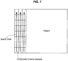
- FIG. 6 and FIG. 7 are explanatory diagrams showing the blind decoding.
- the UE performs CRC check by demasking each CCE with its own C-RNTI. Further, the UE performs the blind decoding on each CCE in an order shown in FIG. 7 . That is, the UE performs the CRC check of each CCE on an assumption that each CCE is addressed to itself, and determines the CCE with a normal result as the CCE addressed to itself.
- the CCE aggregation is a mode in which CCEs are transmitted at an amount that is one, two, four, or eight times the typical unit of the CCE.
- the CCEs are transmitted by being repeated eight times.
- the check bit by the CRC is added to the result of the eight times of repetition. Accordingly, the UE performs the blind decoding by taking into account a possibility that the CCE aggregation has been performed.
- RNTIs such as a P-RNTI for acquiring information for paging and an SI-RNTI for acquiring system information exist. Accordingly, the UE performs the blind decoding by assuming by which of the RNTIs each of the CCEs is to be identified.
- the base station due to the introduction of the aforementioned MTC terminals, increases are expected in a number of terminals existing within each cell, a number of terminals the base station is to contain in an Active mode, and a number of terminals for the base station 10 to simultaneously control in the PDCCH. Further, the CCE included in the PDCCH also increases accompanying the increase in the number of terminals simultaneously controlled in the PDCCH.
- load of the blind decoding in the UE increases due to a range requiring the blind decoding by the UE (including the MTC terminal) being broader.
- the extra-low power consumption is required in the MTC terminal, so the increase in the load of the blind decoding is problematic.
- each embodiment is implemented by using an MTC-GP_RNTI which is an identifier of an MTC group assigned to the MTC terminal 20.
- MTC-GP_RNTI is an identifier of an MTC group assigned to the MTC terminal 20.
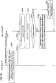
- FIG. 8 is a sequence diagram showing an example of a method of assigning C-RNTI and MTC-GP_RNTI. As shown in FIG. 8 , firstly, in a random access procedure formed of Step 1 to Step 4, the C-RNTIs are assigned to each MTC terminal 20.
- the MTC terminal 20 transmits a preamble to a random access window in a radio frame (Step 1).
- the base station 10 transmits a random access response to the MTC terminal 20 (Step 2).
- the base station 10 assigns a Temporary C-RNTI to the MTC terminal 20 in this random access response.
- the MTC terminal 20 transmits an L2/L3 message to the base station 10 (Step 3).
- the MTC terminal 20 determines that a random access had been successful by receiving a contention resolution message transmitted from the base station 10 (Step 4), and begins using the Temporary C-RNTI assigned in Step 2 as the C-RNTI.
- an MTC category setting procedure formed of Step 5 and Step 6 is performed. More specifically described, since the MTC terminal 20 is set with information of an MTC category indicating whether the MTC terminal 20 itself is an MTC terminal or not, the MTC terminal 20 is aware that itself is an MTC terminal. Due to this, the MTC terminal 20 notifies the base station 10 of the MTC category (Step 5), and receives a notification confirming signal from the base station 10 (Step 6). Notably, the MTC category may include information indicating a capacity of the MTC terminal 20, such as whether the MTC terminal 20 is compliant with a long sleep mode for over one month or not.
- the MTC-GP_RNTI is assigned to the MTC terminal 20. More specifically described, the MTC terminal 20 performs an MTC group setting request to the base station 10 (Step 7). The base station 10 transfers the aforementioned setting request to the MME 12 together with a terminal ID of the MTC terminal 20 (a unique number described in an SIM, and is different from the RNTI).
- the MME 12 is a device that handles the unique information of the terminals, receives correspondence information of an MTC group and the terminal IDs of the terminals that are granted to enter the MTC group from the MTC server 30, and retains the correspondence information.
- the MME 12 determines whether an MTC terminal 20 having the terminal ID transferred from the base station 10 is allowed to enter the MTC group or not based on the correspondence information, and if the MTC terminal 20 is allowed to enter, the MME 12 transmits an MTC group setting confirming signal to the base station 10.
- the base station 10 transmits the MTC-GP_RNTI to the MTC terminal 20 together with the MTC group setting confirming signal (Step 8). Then, the MTC terminal 20 becomes capable of using the MTC-GP_RNTI by receiving the MTC group setting confirming signal and the MTC-GP_RNTI from the base station 10.
- the method of assigning the MTC-GP_RNTI is described above, however, the method of assigning the MTC-GP_RNTI is not limited to the above example.
- information such as an AC (Access Class) that is predeterminedly set in the MTC terminal 20 may be used as the MTC-GP_RNTI, and the MTC-GP_RNTI may be assigned to the MTC terminal 20 by a human operation.
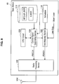
- FIG. 9 is an explanatory diagram showing a configuration of a base station 10 of the first embodiment of the invention.
- the base station 10 of the first embodiment includes an antenna 104, a radio processing section 108, a storage section 112, a scheduler 116, a control signal generating section 120, a CRC circuit 124, and a data mapping section 128.
- the antenna 104 functions as a transmitter section that transmits a transmitter signal such as a PDCCH (control signal) and a PDSCH (data signal) supplied from the radio processing section 108 as a radio signal, and as a receiver section that converts the radio signal transmitted from a radio communication device such as an MTC terminal 20 into an electric receiver signal, and supplies the receiver signal to the radio processing section 108.
- a transmitter signal such as a PDCCH (control signal) and a PDSCH (data signal) supplied from the radio processing section 108 as a radio signal
- a receiver section that converts the radio signal transmitted from a radio communication device such as an MTC terminal 20 into an electric receiver signal, and supplies the receiver signal to the radio processing section 108.
- the base station 10 may include a plurality of antennas.
- the base station 10 is capable of realizing an MIMO (Multiple Input, Multiple Output) communication, a diversity communication and the like.
- MIMO Multiple Input, Multiple Output
- the radio processing section 108 performs radio processes for transmission such as modulation, DA conversion, filtering, amplification, and up-conversion of the transmitter signal such as the PDCCH supplied from the control signal generating section 120, the PDSCH supplied from the data mapping section, and the like. Further, the radio processing section 108 performs radio processes for reception such as down-conversion, filtering, DA conversion, and demodulation of the receiver signal supplied from the antenna 104.
- the storage section 112 stores the MTC-GP_RNTIs, the C-RNTIs and the like that are assigned to the respective MTC terminals 20. Further, although depiction is omitted in FIG. 9 , the storage section 112 also stores other RNTIs such as SI-RNTIs, P-RNTIs, and RA-RNTIs.
- the scheduler 116 allots a resource to each MTC terminal 20 for data communication. That is, the scheduler 116 allots resource blocks among the PDSCH that the respective MTC terminals 20 are to receive, and resource blocks among the PUSCH that the respective MTC terminals 20 are to transmit.
- the control signal generating section 120 generates a PDCCH formed of a plurality of CCEs.
- the control signal generating section 120 generates a CCE including information indicating a second search space arranged within data region (reference information) and a check bit obtained by the CRC circuit 124 by masking the aforesaid information by the MTC-GP_RNTI.
- the masking may be an exclusive disjunction calculation (XOR) of the information indicating the second search space and the MTC-GP_RNTI, or may be a serial coupling of the information indicating the second search space and the C-RNTI.
- XOR exclusive disjunction calculation
- an MTC terminal 20 within an MTC group to which the MTC-GP_RNTI is assigned can be designated as a destination of the information indicating the second search space.
- control signal generating section 120 may designate the designation of the CCE simply by attaching the MTC-GP_RNTI to the information indicating the second search space.
- control signal generating section 120 generates information for mapping in the second search space, and supplies the same to the data mapping section 128 together with information indicating a position of the second search space.
- the information for mapping in the second search space is the resource information for the respective MTC terminals 20 within the MTC group to which the MTC-GP_RNTI is assigned.
- a check bit obtained by the CRC circuit 124 by masking the aforesaid information with the C-RNTIs of the respective MTC terminals 20 is added to the resource information for the respective MTC terminals 20.
- the data mapping section 128 maps user data for each MTC terminal 20 supplied from an upper layer in the resource block allotted by the scheduler 116 among the PDSCH that the respective MTC terminals 20 are to receive. Further, the data mapping section 128 maps the resource information of the respective MTC terminals 20 supplied from the control signal generating section 120 in the second search space.
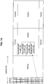
- a disposition relationship of the CCE, the second search space, the allotted resource and the like will be described more specifically with reference to FIG. 10 .
- FIG. 10 is an explanatory diagram showing the disposition relationship of the CCE, the second search space, and the allotted resource.
- a CCE #1 describes information indicating a position of a second search space #1 for an MTC group having an MTC-GP_RNTI corresponding to a check bit added to the CCE #1.
- resource information #1 indicates a resource block #1 for the MTC terminal 20 having a C-RNTI corresponding to a check bit added to the resource information #1.
- resource information #2 indicates a resource block #2 for the MTC terminal 20 having a C-RNTI corresponding to a check bit added to the resource information #2.
- a CCE #2 shown in FIG. 10 describes information indicating a position of a second search space #2 for an MTC group having an MTC-GP_RNTI corresponding to a check bit added to the CCE #2. Further, of a plurality of resource information included in the second search space #2, for example, resource information #3 indicates a resource block #3 for the MTC terminal 20 having a C-RNTI corresponding to a check bit added to the resource information #3.
- the CCE and the second search space may be disposed in the same sub frame as with the CCE #1 and the second search space #1, or may be disposed in different sub frames as with the CCE #2 and the second search space #2.
- Such a relationship of the CCE and the second search space may fixedly be set by signaling in advance, or may be designated by the CCE.
- the resource blocks are disposed in a sub frame that is after the sub frame of the second search space, such as with the resource block #1 and the resource block #2.
- Such a relationship of the second search space and the allotted resource blocks of the respective MTC terminals 20 may fixedly be set by signaling in advance, or may be designated by the second search space.
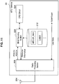
- FIG. 11 is an explanatory diagram showing the configuration of the MTC terminal 20 of the first embodiment.
- the MTC terminal 20 of the first embodiment includes an antenna 204, a radio processing section 208, a storage section 212, a blind decoding section 220, and a CRC circuit 224.
- the antenna 204 functions as a transmitter section that transmits a transmitter signal such as a PUSCH(data signal) supplied from the radio processing section 208 as a radio signal, and as a receiver section that converts the radio signal such as the PDCCH and the PDSCH transmitted from a base station 10 into an electric receiver signal, and supplies the receiver signal to the radio processing section 208.
- a transmitter signal such as a PUSCH(data signal) supplied from the radio processing section 208 as a radio signal
- a receiver section that converts the radio signal such as the PDCCH and the PDSCH transmitted from a base station 10 into an electric receiver signal, and supplies the receiver signal to the radio processing section 208.
- the MTC terminal 20 may include a plurality of antennas.
- the MTC terminal 20 is capable of realizing an MIMO (Multiple Input, Multiple Output) communication, a diversity communication and the like.
- MIMO Multiple Input, Multiple Output
- the radio processing section 208 performs radio processes for transmission such as modulation, DA conversion, filtering, amplification, and up-conversion of user data supplied from an upper layer. Further, the radio processing section 208 performs radio processes for reception such as down-conversion, filtering, DA conversion, and demodulation of the receiver signal supplied from the antenna 104.
- the storage section 212 stores for example the MTC-GP_RNTIs, the C-RNTIs and the like that are assigned from the base station 10. Further, although depiction is omitted in FIG. 11 , the storage section 212 also stores other RNTIs such as SI-RNTI, P-RNTI, and RA-RNTI.
- the blind decoding section 220 extracts the CCE identified by the MTC-GP_RNTI assigned to the MTC terminal 20 by the blind decoding. More specifically described, the blind decoding section 220 operates in cooperation with the CRC circuit 224 to perform CRC check by demasking each CCE by the MTC-GP_RNTI assigned to the MTC terminal 20. Then, the blind decoding section 220 extracts the CCE with a normal result, and specifies the second search space based on the information described in the CCE. For example, the blind decoding section 220 extracts the CCE #1 shown in FIG. 10 from the PDCCH, and specifies the second search space #1 based on the information described in the CCE #1.
- the blind decoding section 220 acquires the resource information addressed to itself by performing the blind decoding using the C-RNTI on the second search space specified from the CCE. More specifically, the blind decoding section 220 operates in cooperation with the CRC circuit 224 to perform CRC check by demasking each resource information in the second search space using the C-RNTI. Then, the blind decoding section 220 acquires the resource information with a normal result as the resource information addressed to itself. Thereafter, the radio processing section 208 performs the transmission process or the reception process in the resource block indicated by the resource information. For example, the blind decoding section 220 acquires the resource information #1 in the second search space #1 shown in FIG. 10 as the resource information addressed to itself. Thereafter, the radio processing section 208 performs the reception process in the resource block #1 indicated by the resource information #1.
- the resource information for a large number of MTC terminals 20 can be contained. Further, since a number of the CCEs in the PDCCH can be suppressed, the search space in which the MTC terminal 20 performs the blind decoding can be reduced. As a result, load related to the blind decoding in the MTC terminal 20 can be reduced.
- the resource information for the respective MTC terminals 20 are mapped in the second search space was described above, the first embodiment is not limited to this example. For example, communication controlling information for each MTC terminal 20 such as transmission power and transmission rate, and other various types of information for each MTC terminal 20 may be mapped in the second search space.
- FIG. 12 is a sequence diagram showing the operation of the radio communication system 1 of the first embodiment of the invention.
- the base station 10 firstly decides a second search space for one MTC group (S310). Then, the control signal generating section 120 of the base station 10 describes information indicating the decided second search space in the CCE in the PDCCH in a state capable of being identified by MTC-GP_RNTI assigned to the MTC group (S320). More specifically, the control signal generating section 120 adds a check bit obtained by the CRC circuit 124 by masking the information indicating the second search space with the MTC-GP_RNTI to the CCEs.
- the data mapping section 128 of the base station 10 maps the resource information for each MTC terminal 20 belonging to the MTC group in the second search space of the PDSCH in a state capable of being identified by C-RNTI assigned to each MTC terminal 20 (S330). Thereafter, the base station 10 transmits the PDCCH and the PDSCH (S340).
- the blind decoding section 220 of the MTC terminal 20 performs the blind decoding on the respective CCEs in the PDCCH using the MTC-GP_RNTI assigned to itself (S350), and specifies the second search space for the MTC group including the terminal itself (S360).
- the blind decoding section 220 of the MTC terminal 20 performs the blind decoding on the second search space in the PDSCH using the C-RNTI (S370), and acquires the resource information for the terminal itself (S380). Thereafter, the MTC terminal 20 performs the reception process or the transmission process in the resource block indicated by the acquired resource information.
- the base station 10 of the first embodiment of the invention transmits the PDCCH by describing the information indicating the second search space in the CCEs in the state capable of being identified by the MTC-GP_RNTI.
- the base station 10 transmits the PDCCH by describing the resource information for the MTC terminal 20 in the CCEs in a state capable of being identified by the C-RNTI of the MTC terminal 20 may also be possible.
- the MTC terminal 20 may perform the blind decoding of the PDCCH by using both the MTC-GP_RNTI and the C-RNTI. Even in the case of performing the blind decoding of the PDCCH by using both the MTC-GP_RNTI and the C-RNTI, since the search space is made small according to the first embodiment of the invention, load on the MTC terminal 20 can be suppressed sufficiently.
- the MTC terminal 20 may perform the blind decoding by using only the C-RNTI.
- the base station 10 cannot handle the MTC-GP_RNTI
- a case in which the MTC terminal 20 is connected to a new base station 10 by a hand-over, or a case in which the base station 10 does not have a capability to handle the MTC-GP_RNTI is expected.
- the MTC terminal 20 may change the RNTI to be used in the blind decoding by requesting a setting change to the base station 10.
- FIG. 13 is a sequence diagram showing an example of a method of changing the RNTI used for the blind decoding.
- the MTC terminal 20 performs the blind decoding of the PDCCH by using both the MTC-GP_RNTI and the C-RNTI
- a setting request of MTC-GP_Only_Mod can be transmitted to the base station 10 (S410).
- the base station 10 sets the MTC-GP_Only_Mod that describes the information indicating at least the second search space for the MTC group to which the MTC terminal 20 belongs in the CCE in a state capable of being identified by the MTC-GP_RNTI. Then, the base station 10 transmits a setting confirming signal of the MTC-GP_Only_Mod to the MTC terminal 20 (S420). Notably, the base station 10 may transmit the setting confirming signal of the MTC-GP_Only_Mod to all of the MTC terminals belonging to the MTC group.
- the MTC terminal 20 After receiving the setting confirming signal of the MTC-GP_Only_Mod, the MTC terminal 20 performs the blind decoding by using only the MTC-GP_RNTI.
- the base station 10 releases the setting of the MTC-GP_Only_Mod, and transmits a release confirming signal of the MTC-GP_Only_Mod to the MTC terminal 20 (S440).
- the MTC terminal 20 After having received the release confirming signal of the MTC-GP_Only_Mod, the MTC terminal 20 again performs the blind decoding of the PDCCH using both the MTC-GP_RNTI and the C-RNTI.
- the first embodiment of the invention was described. Now, a second embodiment of the invention will be described. Notably, since the second embodiment to the seventh embodiment described below have a large number of portions in common with the first embodiment, detailed descriptions for the portions in common with the first embodiment will be omitted. Further, the second embodiment to the seventh embodiment will be described by reusing the configurational diagram of the base station 10 shown in FIG. 9 and the configurational diagram of the MTC terminal 20 shown in FIG. 11 .
- FIG. 14 is an explanatory diagram showing an example of disposition of the second search space for a certain MTC group.
- a base station 10 may dispose second search spaces #1 to #3 at a same position that one CCE #1 indicates over a plurality of sub frames.
- an MTC terminal 20 needs to know over how many sub frames the second search spaces are to be disposed at the same position. Due to this, the base station 10 may notify a number of the sub frames in CCE, or may notify the number of the sub frames to the MTC terminal 20 in advance.
- an MTC terminal 20 searches the following Ofdm symbol again in the frequency direction. Due to this, in an LTE, a search in the frequency direction with a minimum width of 5 MHz and a maximum width of 20 MHz is required.
- the MTC terminal 20 in some cases is required to have an extra low power consumption, and of an operation efficiency of a digital circuit, it is effective to make the search width in the frequency direction be 5 MHz or less, for example, 1 MHz or less.
- the base station 10 of the third embodiment disposes the CCEs for the same MTC group in a predetermined sub carrier.
- specific descriptions will be given with reference to FIG. 15 .
- FIG. 15 is an explanatory diagram showing an example of disposition of the CCEs for each MTC group.
- the base station 10 of the third embodiment for example disposes CCE for an MTC terminal 20 belonging to an MTC group 1 in a sub carrier x, and disposes CCE for an MTC terminal 20 belonging to an MTC group 2 in a sub carrier y.
- the base station 10 may notify the MTC terminals 20 in advance of information indicating which sub carrier the CCE for each MTC group is going to be disposed in.
- the MTC terminal 20 belonging to the MTC group 1 can simply perform the blind decoding only on the sub carrier x in a time direction, and the MTC terminal 20 belonging to the MTC group 2 can simply perform the blind decoding only on the sub carrier y in the time direction.
- load related to the blind decoding in the MTC terminal 20 can significantly be reduced.
- MTC terminals 20 belong to one MTC group and one MTC-GP_RNTI is assigned was described.
- MTC terminals 20 are grouped separately for uplink and downlink is also expected.
- the fourth embodiment focuses on this feature, and MTC terminals 20 of the fourth embodiment belong to a plurality of MTC groups, and a plurality of MTC-GP_RNTIs are assigned.
- a specific example will be described with reference to FIG. 16 .
- FIG. 16 is an explanatory diagram showing a specific example of an MTC group to which MTC terminals 20 belong.
- the MTC terminals 20 of the fourth embodiment belong to an uplink MTC group and a downlink MTC group.
- an MTC terminal 20A belongs to a downlink MTC group 1 and an uplink MTC group 1
- an MTC terminal 20B belongs to the downlink MTC group 1 and an uplink MTC group 3.
- MTC-DownLink_RNTI that is a downlink group identifier and MTC-UpLink_RNTI that is an uplink group identifier are assigned to each MTC terminal 20.
- a base station 10 generates the CCE including information indicating a second search space for the uplink by using the MTC-UpLink_RNTI, and generates the CCE including information indicating a second search space for the downlink by using the MTC-DownLink_RNTI.
- the base station 10 in a case of describing the information indicating the second search space for the uplink MTC group 1 in the CCE #4 shown in FIG. 17 , the base station 10 generates the CCE #4 by using the MTC-UpLink_RNTI assigned to the uplink MTC group 1. Similarly, in a case of describing the information indicating the second search space for the downlink MTC group 2 in the CCE #5 shown in FIG. 17 , the base station 10 generates the CCE #5 by using the MTC-DownLink_RNTI assigned to the downlink MTC group 2.
- the MTC terminal 20 can extract the CCE for the MTC group to which the MTC terminal 20 belongs by performing blind decoding on each CCE in the PDCCH by using the MTC-DownLink_RNTI and the MTC-UpLink_RNTI.
- the first embodiment to the fourth embodiment make the search space in the PDCCH small by using the second search space.
- the fifth embodiment to the seventh embodiment described below make the search space in the PDCCH small by describing the resource information shared by a plurality of MTC terminals 20 configuring an MTC group in the CCE.
- the fifth embodiment to the seventh embodiment will orderly be described.
- a base station 10 can use a common command for instructing a plurality of MTC terminals 20 to report the accumulated information.
- the base station 10 describes resource information indicating a resource block to which the plurality of MTC terminals 20 in an MTC group is to perform a reception process in the CCE. Further, the base station 10 transmits the CCE in a state capable of being identified by MTC-GP_RNTI by adding a check bit based on the MTC-GP_RNTI assigned to the MTC group to the CCEs.
- the plurality of MTC terminals 20 in the MTC group performs blind decoding using the MTC-GP_RNTI, and extracts the CCE identified by the MTC-GP_RNTI. Further, the plurality of MTC terminals 20 in the MTC group simultaneously performs the reception process in the resource block indicated by the resource information described in the extracted CCE.
- the search space in the PDCCH can further be made smaller.
- the base station 10 In an uplink, if the plurality of MTC terminals 20 performs a transmission process in the same resource block, uplink data collapses at the base station 10. Thus, the base station 10 describes resource information indicating a reference resource block for the uplink of the MTC group in the CCE. Further, the base station 10 transmits the CCE in a state capable of being identified by MTC-GP_RNTI by adding a check bit based on the MTC-GP_RNTI assigned to the MTC group to the CCEs.
- the plurality of MTC terminals 20 in the MTC group performs blind decoding using the MTC-GP_RNTI, and extracts the CCE identified by the MTC-GP_RNTI. Further, the plurality of MTC terminals 20 in the MTC group specifies the reference resource block indicated by the resource information described in the extracted CCE, and performs the transmission process in the resource block that is in a positional relationship with the reference resource block as set in advance.
- this feature will be described more specifically with reference to FIG. 18 .
- FIG. 18 is an explanatory diagram showing a relationship of a reference resource block and an uplink resource block of each MTC terminal 20. As shown in FIG. 18 , for example, resource information indicating a resource block #1 as the reference resource block of the uplink of a MTC group 1 is described in CCE #6.
- the MTC group 1 is configured of MTC terminals 20A to 20D, and a relative position of a resource block to be used for the uplink by each MTC terminal 20 from the reference resource block is set.
- the MTC terminals 20A to 20D specify the resource block #1 that is the reference resource block, and perform the transmission process by using the resource block that is at the set relative position from the reference resource block.
- the MTC terminal 20A uses the resource block #1 that is the reference resource block
- the MTC terminal 20B uses a resource block #2 that is adjacent with the resource block #1 in the time direction
- the MTC terminal 20C uses a resource block #3 that is adjacent with the resource block #2 in the time direction
- the MTC terminal 20D uses a resource block #4 that is adjacent with the resource block #3 in the time direction.
- settings may be made with a reference resource block as an origin to use resource blocks that are adjacent in a frequency direction in an order of MTC terminals 20A, 20B, 20C, and 20D.
- the MTC terminal 20A uses a resource block #1 that is the reference resource block
- the MTC terminal 20B uses the resource block #5 that is adjacent to the resource block #1 in the frequency direction.
- the MTC terminal 20C uses the resource block #6 that is adjacent to the resource block #5 in the frequency direction
- the MTC terminal 20D uses the resource block #7 that is adjacent to the resource block #6 in the frequency direction.
- the base station 10 may signal the positional relationship of the resource block to which each MTC terminal 20 is to perform the transmission process and the reference resource block in advance to each MTC terminal 20.
- the fifth embodiment may be implemented by replacing the MTC-GP_RNTI with the C-RNTI.
- the base station 10 can allot the same C-RNTI to a plurality of MTC terminals 20, and the C-RNTI may be used in a similar way as with the above MTC-GP_RNTI.
- FIG. 20 is an explanatory diagram showing the operation of the radio communication system 1 of the fifth embodiment.
- the base station 10 transmits relative position information indicating the positional relationship of the resource blocks to which the MTC terminals 20 are to perform the transmission to the MTC terminals 20 in advance (S510).
- the control signal generating section 120 of the base station 10 describes the resource information for each MTC terminal 20 belonging to the MTC group in a state capable of being identified by the MTC-GP_RNTI assigned to the MTC group to the CCEs in the PDCCH (S520). Specifically, the control signal generating section 120 adds the check bit obtained by the CRC circuit 124 by masking the resource information for each MTC terminal 20 with the MTC-GP_RNTI to the CCEs. Then, the base station 10 transmits the PDCCH including the CCE in which the resource information for each MTC terminal 20 is described (S530).
- the blind decoding section 220 of the MTC terminal 20 performs blind decoding on each CCE in the PDCCH by using the MTC-GP_RNTI assigned to itself (S540), and obtains the resource information for the MTC group including itself (S550).
- the MTC terminal 20 performs the reception process in the resource block indicated by the resource information (S 570).
- the MTC terminal 20 performs the transmission process in the resource block that is in the positional relationship as indicated by the relative position information with the reference resource block indicated by the resource information (S 580).
- the search space in the PDCCH can be made small. As a result, load related to the blind decoding in the MTC terminals 20 can be reduced.
- the sixth embodiment is implemented by adapting the third embodiment described with reference to FIG. 15 to the fifth embodiment. Specifically, a base station 10 according to the sixth embodiment disposes a CCE including resource information for one MTC group in a predetermined sub carrier. According to the configuration, since an MTC terminal 20 simply needs to perform blind decoding on only the predetermined sub carrier in a time direction, load related to the blind decoding in the MTC terminal 20 can be reduced significantly.
- the seventh embodiment is implemented by adapting the fourth embodiment described with reference to FIG. 16 to the fifth embodiment.
- an MTC terminal 20 of the seventh embodiment belongs to an uplink MTC group and a downlink MTC group. Due to this, the MTC terminal 20 is assigned with MTC-DownLink_RNTI that is a group identifier for downlink, and MTC-UpLink_RNTI that is a group identifier for uplink.
- the base station 10 generates the CCE including the uplink resource information of the MTC group by using the MTC-UpLink_RNTI, and generates the CCE including the downlink resource information by using the MTC-DownLink_RNTI.
- the MTC terminal 20 can extract the CCE for the MTC group to which the MTC terminal 20 belongs by performing blind decoding on each CCE in the PDCCH by using the MTC-DownLink_RNTI and the MTC-UpLink_RNTI.
- the resource information for a large number of MTC terminals 20 can be stored by mapping the resource information (assign, grant) for each MTC terminal 20 in the second search space in the PDSCH. Further, since a number of the CCEs in the PDCCH can be suppressed, the search space in which the MTC terminal 20 performs the blind decoding can be reduced. As a result, load related to the blind decoding in the MTC terminal 20 can be reduced.
- the resource information described in the CCE in the PDCCH can be shared by the plurality of MTC terminals 20 in the MTC group. Due to this, the resource information for each MTC terminal 20 no longer needs to be described in separate CCEs, so the search space in the PDCCH can be made small. As a result, load related to the blind decoding in the MTC terminals 20 can be reduced.
- respective steps in the processes by the base station 10 and the MTC terminal 20 in the description do not necessarily be performed in chronological orders as described in sequence diagrams.
- the respective steps in the processes by the base station 10 and the MTC terminal 20 may be performed in orders different from the orders described the in sequence diagrams, or may be performed in parallel.
- computer programs for causing hardware such as CPUs, ROMs, and RAMs installed in the base station 10 and the MTC terminal 20 to exhibit similar functions as the respective configurations of the base station 10 and the MTC terminal 20 may be produced. Further, storage media storing such computer programs may also be provided.
Claims (12)
- Funkendgerät (20), das Folgendes umfasst:einen Empfängerabschnitt (204), der konfiguriert ist, ein Steuersignal von einer Basisstation (10) zu empfangen; undeinen Blinddecodierungsabschnitt (220), der konfiguriert ist, Betriebsmittelinformationen, die durch Gruppenkennungen, die mehreren Funkendgeräten, die das Funkendgerät enthalten, zugewiesen sind, identifiziert werden, aus dem Steuersignal, das durch den Empfängerabschnitt empfangen wurde, zu erfassen; dadurch gekennzeichnet, dassder Empfängerabschnitt ferner konfiguriert ist, das Steuersignal in der Weise zu empfangen, dass Aufwärtsstreckenbetriebsmittelinformationen durch eine Aufwärtsstreckengruppenkennung, die den mehreren Funkendgeräten zugewiesen ist, identifiziert werden und Abwärtsstreckenbetriebsmittelinformationen durch eine Abwärtsstreckengruppenkennung, die den mehreren Funkendgeräten zugewiesen ist, identifiziert werden.
- Funkendgerät nach Anspruch 1, wobei die Abwärtsstreckenbetriebsmittelinformationen Informationen sind, die ein Betriebsmittel angeben, damit die mehreren Funkendgeräte einen gleichzeitigen Empfang durchführen können.
- Funkendgerät nach Anspruch 2, wobei die Aufwärtsstreckenbetriebsmittelinformationen Informationen sind, die ein Betriebsmittel angeben, das eine Referenz sein soll, damit jedes der mehreren Funkendgeräte eine Relativposition eines Sendebetriebsmittels festsetzen kann.
- Funkendgerät nach Anspruch 1, wobei der Erfassungsabschnitt konfiguriert ist, Informationen, die durch eine Endgerätekennung, die dem Funkendgerät zugewiesen ist, identifiziert werden, aus dem Steuersignal zu erfassen, wenn bestimmt wird, dass durch die Basisstation keine Gruppenkennung verwendet wird.
- Verfahren zur Funkkommunikation, das durch ein Funkendgerät (20) durchgeführt wird, wobei das Verfahren die folgenden Schritte umfasst:Empfangen eines Steuersignals von einer Basisstation (10); undErfassen durch blindes Decodieren von Betriebsmittelinformationen, die durch Gruppenkennungen, die mehreren Funkendgeräten, die das Funkendgerät enthalten, zugewiesen sind, identifiziert werden, aus dem Steuersignal;gekennzeichnet durchEmpfangen des Steuersignals in der Weise, dass Aufwärtsstreckenbetriebsmittelinformationen durch eine Aufwärtsstreckengruppenkennung, die den mehreren Funkendgeräten zugewiesen ist, identifiziert werden und Abwärtsstreckenbetriebsmittelinformationen durch eine Abwärtsstreckengruppenkennung, die den mehreren Funkendgeräten zugewiesen ist, identifiziert werden.
- Programm, um zu bewirken, dass ein Computer als ein Funkendgerät (20) arbeitet, das Folgendes enthält:einen Empfängerabschnitt (204), der ein Steuersignal von einer Basisstation (10) empfängt; undeinen Blinddecodierungsabschnitt (220), der Betriebsmittelinformationen, die durch Gruppenkennungen, die mehreren Funkendgeräten, die das Funkendgerät enthalten, zugewiesen sind, aus dem Steuersignal, das durch den Empfängerabschnitt empfangen wurde, erfasst; dadurch gekennzeichnet, dass der Empfängerabschnitt das Steuersignal in der Weise empfängt, dass Aufwärtsstreckenbetriebsmittelinformationen durch eine Aufwärtsstreckengruppenkennung, die den mehreren Funkendgeräten zugewiesen ist, identifiziert werden und Abwärtsstreckenbetriebsmittelinformationen durch eine Abwärtsstreckengruppenkennung, die den mehreren Funkendgeräten zugewiesen ist, identifiziert werden.
- Basisstation (10), die Folgendes umfasst:einen Steuersignalerzeugungsabschnitt (120), der konfiguriert ist, ein Steuersignal zu erzeugen, das Betriebsmittelinformationen enthält, die durch Gruppenkennungen, die mehreren Funkendgeräten (20) zugewiesen sind, identifiziert werden; undeinen Senderabschnitt (104), der konfiguriert ist, das Steuersignal, das durch den Steuersignalerzeugungsabschnitt erzeugt wurde, zu senden; dadurch gekennzeichnet, dassden mehreren Funkendgeräten eine Aufwärtsstreckengruppenkennung und eine Abwärtsstreckengruppenkennung zugewiesen sind, undder Steuersignalerzeugungsabschnitt ferner konfiguriert ist, das Steuersignal in der Weise zu erzeugen, dass Aufwärtsstreckenbetriebsmittelinformationen durch die Aufwärtsstreckengruppenkennung identifiziert werden und Abwärtsstreckenbetriebsmittelinformationen durch die Abwärtsstreckengruppenkennung identifiziert werden.
- Basisstation nach Anspruch 7, wobei der Steuersignalerzeugungsabschnitt ferner konfiguriert ist, die Betriebsmittelinformationen, die durch dieselbe Gruppenkennung identifiziert werden, in einem vorgegebenen Frequenzbereich in einem Steuerbereich zum Senden des Steuersignals anzuordnen.
- Basisstation nach Anspruch 8, wobei der Steuersignalerzeugungsabschnitt ferner konfiguriert ist, ein Prüfbit, das durch Maskieren der Betriebsmittelinformationen mit der Gruppenkennung erhalten wird, zu den Betriebsmittelinformationen zu addieren.
- Verfahren zur Funkkommunikation, wobei das Verfahren die folgenden Schritte umfasst:Erzeugen eines Steuersignals, das Betriebsmittelinformationen enthält, die durch Gruppenkennungen, die mehreren Funkendgeräten (20) zugewiesen sind, identifiziert werden; undSenden des Steuersignals;gekennzeichnet durchZuweisen einer Aufwärtsstreckengruppenkennung und einer Abwärtsstreckengruppenkennung zu den mehreren Funkendgeräten und Erzeugen des Steuersignals in der Weise, dass Aufwärtsstreckenbetriebsmittelinformationen durch die Aufwärtsstreckengruppenkennung identifiziert werden und Abwärtsstreckenbetriebsmittelinformationen durch die Abwärtsstreckengruppenkennung identifiziert werden.
- Programm, um zu bewirken, dass ein Computer als Folgendes arbeitet:ein Steuersignalerzeugungsabschnitt (120), der ein Steuersignal erzeugt, das Betriebsmittelinformationen enthält, die durch Gruppenkennungen, die mehreren Funkendgeräten (20) zugewiesen sind, identifiziert werden; undein Senderabschnitt (104), der das Steuersignal, das durch den Steuersignalerzeugungsabschnitt erzeugt wurde, sendet; dadurch gekennzeichnet, dass den mehreren Funkendgeräten eine Aufwärtsstreckengruppenkennung und eine Abwärtsstreckengruppenkennung zugewiesen sind, undder Steuersignalerzeugungsabschnitt das Steuersignal in der Weise erzeugt, dass Aufwärtsstreckenbetriebsmittelinformationen durch die Aufwärtsstreckengruppenkennung identifiziert werden und Abwärtsstreckenbetriebsmittelinformationen durch die Abwärtsstreckengruppenkennung identifiziert werden.
- Funkkommunikationssystem, das Folgendes umfasst:mehrere Funkendgeräte (20); undeine Basisstation (10), die einen Steuersignalerzeugungsabschnitt (120) enthält, der konfiguriert ist, ein Steuersignal zu erzeugen, das Betriebsmittelinformationen enthält, die durch Gruppenkennungen, die den mehreren Funkendgeräten zugewiesen sind, identifiziert werden, und einen Senderabschnitt (104), der konfiguriert ist, das Steuersignal, das durch den Steuersignalerzeugungsabschnitt erzeugt wurde, zu senden; dadurch gekennzeichnet, dassden mehreren Funkendgeräten eine Aufwärtsstreckengruppenkennung und eine Abwärtsstreckengruppenkennung zugewiesen sind, undder Steuersignalerzeugungsabschnitt ferner konfiguriert ist, das Steuersignal in der Weise zu erzeugen, dass Aufwärtsstreckenbetriebsmittelinformationen durch die Aufwärtsstreckengruppenkennung identifiziert werden und Abwärtsstreckenbetriebsmittelinformationen durch die Abwärtsstreckengruppenkennung identifiziert werden.
Applications Claiming Priority (2)
| Application Number | Priority Date | Filing Date | Title |
|---|---|---|---|
| JP2010225081A JP2012080416A (ja) | 2010-10-04 | 2010-10-04 | 基地局、無線通信方法、プログラム、無線通信システム、および無線端末 |
| PCT/JP2011/068370 WO2012046506A1 (ja) | 2010-10-04 | 2011-08-11 | 基地局、無線通信方法、プログラム、無線通信システム、および無線端末 |
Publications (3)
| Publication Number | Publication Date |
|---|---|
| EP2627143A1 EP2627143A1 (de) | 2013-08-14 |
| EP2627143A4 EP2627143A4 (de) | 2017-01-18 |
| EP2627143B1 true EP2627143B1 (de) | 2019-07-03 |
Family
ID=45927505
Family Applications (1)
| Application Number | Title | Priority Date | Filing Date |
|---|---|---|---|
| EP11830439.3A Not-in-force EP2627143B1 (de) | 2010-10-04 | 2011-08-11 | Basisstation, verfahren für drahtlose kommunikation, programm, drahtloses kommunikationssystem und drahtloses endgerät |
Country Status (7)
| Country | Link |
|---|---|
| US (2) | US9271273B2 (de) |
| EP (1) | EP2627143B1 (de) |
| JP (1) | JP2012080416A (de) |
| CN (1) | CN103141144B (de) |
| BR (1) | BR112013007733A2 (de) |
| TR (1) | TR201911204T4 (de) |
| WO (1) | WO2012046506A1 (de) |
Families Citing this family (29)
| Publication number | Priority date | Publication date | Assignee | Title |
|---|---|---|---|---|
| GB2487782B (en) * | 2011-02-04 | 2015-05-20 | Sca Ipla Holdings Inc | Telecommunications method and system |
| US8848638B2 (en) * | 2011-06-27 | 2014-09-30 | Telefonaktiebolaget L M Ericsson (Publ) | Cellular communication system support for limited bandwidth communication devices |
| JP5826937B2 (ja) * | 2012-07-27 | 2015-12-02 | 京セラ株式会社 | 移動通信システム、基地局、ユーザ端末、及びプロセッサ |
| JP6152253B2 (ja) * | 2012-08-29 | 2017-06-21 | 株式会社Nttドコモ | 無線基地局 |
| JP6082288B2 (ja) * | 2012-10-16 | 2017-02-15 | シャープ株式会社 | 無線通信システム |
| CN103841603B (zh) * | 2012-11-20 | 2019-05-31 | 北京三星通信技术研究有限公司 | 上行分组调度的方法及设备 |
| CN104756433B (zh) | 2012-12-03 | 2017-10-31 | 索尼公司 | 用于lte的基于组的pdcch能力 |
| GB2508595B (en) * | 2012-12-03 | 2020-08-26 | Sony Corp | Telecommunications apparatus and methods |
| US10477557B2 (en) * | 2012-12-03 | 2019-11-12 | Sony Corporation | Transmission of control information to reduced bandwidth terminals |
| GB2508593B (en) * | 2012-12-03 | 2020-08-26 | Sony Corp | Telecommunications apparatus and methods |
| US9036580B2 (en) | 2013-01-17 | 2015-05-19 | Sharp Laboratories Of America, Inc. | Systems and methods for dynamically configuring a flexible subframe |
| JP6200157B2 (ja) * | 2013-01-18 | 2017-09-20 | 株式会社Nttドコモ | 無線基地局及び移動局 |
| GB2510140A (en) | 2013-01-24 | 2014-07-30 | Sony Corp | Virtual carrier for reduced capability wireless devices |
| GB2510137A (en) * | 2013-01-24 | 2014-07-30 | Sony Corp | Mobile communications network including reduced capability devices |
| GB2510138A (en) * | 2013-01-24 | 2014-07-30 | Sony Corp | Allocating communications resources within different frequency ranges according to the relative capability of a communications device |
| GB2510141A (en) * | 2013-01-24 | 2014-07-30 | Sony Corp | Mobile communications network including reduced capability devices |
| JP6040037B2 (ja) * | 2013-01-30 | 2016-12-07 | シャープ株式会社 | 無線通信システム |
| CN104113925B (zh) * | 2013-04-18 | 2019-06-11 | 中兴通讯股份有限公司 | 授权信令发送、获取方法及装置 |
| CN104521286B (zh) * | 2013-08-07 | 2020-08-14 | 华为技术有限公司 | 一种数据传输的方法、装置和系统 |
| WO2015019454A1 (ja) * | 2013-08-07 | 2015-02-12 | 富士通株式会社 | 無線通信システム、基地局、通信端末及び無線通信方法 |
| JP6292530B2 (ja) * | 2013-08-07 | 2018-03-14 | サン パテント トラスト | 通信装置、通信方法及び集積回路 |
| WO2015112071A2 (en) * | 2014-01-22 | 2015-07-30 | Telefonaktiebolaget L M Ericsson (Publ) | Handling of different control channel configurations for one or more wireless devices in a radio network |
| EP3998819B1 (de) * | 2014-06-24 | 2024-04-24 | Sun Patent Trust | Endgerät, basisstation, sendeverfahren und empfangsverfahren |
| CN107211418B (zh) * | 2015-01-29 | 2021-06-01 | 株式会社Ntt都科摩 | 用户终端、无线基站及无线通信方法 |
| KR102335645B1 (ko) * | 2015-02-05 | 2021-12-06 | 한국전자통신연구원 | 디바이스 특성에 따른 통신 방법 및 이를 이용한 자원 할당 장치 |
| US10498487B2 (en) | 2015-07-10 | 2019-12-03 | Lg Electronics Inc. | Method and device for transmitting control information in wireless communication system |
| US11140634B2 (en) * | 2017-03-23 | 2021-10-05 | Apple Inc. | Narrowband internet-of-things (NB-IOT) enhancements |
| EP3725124A1 (de) | 2017-12-14 | 2020-10-21 | Telefonaktiebolaget LM Ericsson (publ) | Planung einer datenübertragung |
| WO2020172762A1 (en) * | 2019-02-25 | 2020-09-03 | Huawei Technologies Co., Ltd. | Pscell activation with early data-forwarding for dual connectivity based handover |
Family Cites Families (27)
| Publication number | Priority date | Publication date | Assignee | Title |
|---|---|---|---|---|
| US7616610B2 (en) * | 2005-10-04 | 2009-11-10 | Motorola, Inc. | Scheduling in wireless communication systems |
| JP2009088577A (ja) * | 2006-01-10 | 2009-04-23 | Mitsubishi Electric Corp | スケジューリング方法および基地局装置 |
| GB0600870D0 (en) * | 2006-01-17 | 2006-02-22 | Siemens Ag | A Method Of Scheduling Groups Of Mobile Users |
| US20100054188A1 (en) * | 2007-03-19 | 2010-03-04 | Atsushi Matsumoto | Wireless Communication Base Station Apparatus and Wireless Communication Method |
| JP2008244559A (ja) * | 2007-03-26 | 2008-10-09 | Sharp Corp | 移動局装置、基地局装置、無線通信システム、制御情報受信方法、制御情報送信方法およびプログラム |
| IL183904A (en) * | 2007-06-13 | 2014-06-30 | Vladimir Yanover | A method and device for allocating film width in a wireless communication system |
| US9344259B2 (en) * | 2007-06-20 | 2016-05-17 | Google Technology Holdings LLC | Control channel provisioning and signaling |
| US8600413B2 (en) | 2007-10-30 | 2013-12-03 | Qualcomm Incorporated | Control arrangement and method for communicating paging messages in a wireless communication system |
| WO2009087742A1 (ja) * | 2008-01-04 | 2009-07-16 | Panasonic Corporation | 無線通信基地局装置、無線通信移動局装置および制御チャネル割当方法 |
| JP5178908B2 (ja) * | 2008-03-26 | 2013-04-10 | コーニンクレッカ フィリップス エレクトロニクス エヌ ヴィ | モバイルシステムにおいて通信するための方法 |
| US8374109B2 (en) * | 2008-03-27 | 2013-02-12 | Qualcomm Incorporated | Methods of sending control information for users sharing the same resource |
| US8326292B2 (en) | 2008-06-03 | 2012-12-04 | Innovative Sonic Limited | Method and apparatus for determining dedicate searching space in physical downlink control channel |
| KR101104963B1 (ko) * | 2008-12-19 | 2012-01-12 | 한국전자통신연구원 | 기지국의 제어채널 관리장치와, 사용자 단말의 제어채널 검색장치 및 이동통신 시스템의 제어채널 할당방법 |
| CN103702365B (zh) * | 2009-03-12 | 2017-06-30 | 太阳专利信托公司 | 终端及控制信道接收方法 |
| US8441996B2 (en) * | 2009-04-02 | 2013-05-14 | Lg Electronics Inc. | Method and apparatus for monitoring control channel in multiple carrier system |
| WO2010118383A1 (en) * | 2009-04-10 | 2010-10-14 | Marvell World Trade Ltd. | Signaling for multi-dimension wireless resource allocation |
| US20110080878A1 (en) * | 2009-07-03 | 2011-04-07 | Robert Novak | Method for control signaling for group of users using ms assignment index |
| KR20110038994A (ko) * | 2009-10-09 | 2011-04-15 | 삼성전자주식회사 | 다중 안테나를 이용하는 무선 통신 시스템에서 다중 사용자 제어 채널 송수신 방법 및 장치 |
| US9019922B2 (en) * | 2010-07-21 | 2015-04-28 | Panasonic Intellectual Property Corporation Of America | Base station, terminal, transmission method and reception method |
| EP2437422A1 (de) * | 2010-10-01 | 2012-04-04 | Panasonic Corporation | Suchräume für Aufwärts- und Abwärtsstrecken-Zuweisung in einem OFDM-basierten mobilen Kommunikationssystem |
| US10638464B2 (en) * | 2011-04-01 | 2020-04-28 | Futurewei Technologies, Inc. | System and method for transmission and reception of control channels in a communications system |
| KR101810121B1 (ko) * | 2011-05-27 | 2017-12-18 | 애플 인크. | 무선 통신 시스템에서 랜덤 액세스의 수행장치 및 방법 |
| KR101943821B1 (ko) * | 2011-06-21 | 2019-01-31 | 한국전자통신연구원 | 무선 통신 시스템에서 제어채널 송수신 방법 |
| US9264208B2 (en) * | 2011-07-12 | 2016-02-16 | Qualcomm Incorporated | Downlink control with control-less subframes |
| US8937916B2 (en) * | 2011-09-26 | 2015-01-20 | Electronics And Telecommunications Research Institute | Resource allocating apparatus and method for machine type communication |
| EP4246848A3 (de) * | 2011-09-30 | 2023-12-20 | InterDigital Patent Holdings, Inc. | Vorrichtungskommunikation mit reduzierter kanalbandbreite |
| US9538502B2 (en) * | 2012-05-01 | 2017-01-03 | Qualcomm Incorporated | Methods and apparatus for managing control and data transmissions for low cost user equipments |
-
2010
- 2010-10-04 JP JP2010225081A patent/JP2012080416A/ja active Pending
-
2011
- 2011-08-11 EP EP11830439.3A patent/EP2627143B1/de not_active Not-in-force
- 2011-08-11 BR BR112013007733A patent/BR112013007733A2/pt not_active Application Discontinuation
- 2011-08-11 WO PCT/JP2011/068370 patent/WO2012046506A1/ja active Application Filing
- 2011-08-11 CN CN201180046988.XA patent/CN103141144B/zh not_active Expired - Fee Related
- 2011-08-11 TR TR2019/11204T patent/TR201911204T4/tr unknown
- 2011-08-11 US US13/818,697 patent/US9271273B2/en not_active Expired - Fee Related
-
2016
- 2016-01-20 US US15/002,271 patent/US10271312B2/en active Active
Non-Patent Citations (1)
| Title |
|---|
| None * |
Also Published As
| Publication number | Publication date |
|---|---|
| EP2627143A1 (de) | 2013-08-14 |
| CN103141144A (zh) | 2013-06-05 |
| US20160135165A1 (en) | 2016-05-12 |
| CN103141144B (zh) | 2018-04-27 |
| US9271273B2 (en) | 2016-02-23 |
| TR201911204T4 (tr) | 2019-08-21 |
| BR112013007733A2 (pt) | 2017-09-26 |
| WO2012046506A1 (ja) | 2012-04-12 |
| EP2627143A4 (de) | 2017-01-18 |
| US10271312B2 (en) | 2019-04-23 |
| US20130150109A1 (en) | 2013-06-13 |
| JP2012080416A (ja) | 2012-04-19 |
Similar Documents
| Publication | Publication Date | Title |
|---|---|---|
| EP2627143B1 (de) | Basisstation, verfahren für drahtlose kommunikation, programm, drahtloses kommunikationssystem und drahtloses endgerät | |
| US10917885B2 (en) | Base station, method, computer readable medium, and system for radio communication for suppressing load of blind decoding using a control signal | |
| US11070951B2 (en) | Systems and methods for multicast resource allocation | |
| AU2021215138B2 (en) | Method for configuring transmission direction of time-frequency resource, and apparatus | |
| CN102083229B (zh) | 非竞争随机接入的调度及前导码发送方法、系统和设备 | |
| CN108141383B (zh) | 配置修改的空口的系统和方法 | |
| CN117651335A (zh) | 信息传输方法和装置 | |
| KR20200024950A (ko) | 머신 타입 통신을 위한 통신 시스템 및 방법 | |
| CN103929779A (zh) | 控制信息的发送、控制信息的接收方法和装置 | |
| KR101706958B1 (ko) | 무선 통신 시스템에서 그룹 통신을 위한 제어 정보 송수신 방법 | |
| EP2820908B1 (de) | Zugangsantwortsignalisierung in einem zellularen kommunikationssystem | |
| CN111865479A (zh) | 一种通信方法及装置 | |
| EP2903384B1 (de) | Verfahren zur übertragung einer erweiterten direktzugriffskanalsequenz und maschinenkommunikationsendgerät | |
| US20180034605A1 (en) | Method and device for transmitting data | |
| CN112703791B (zh) | 一种通信方法及装置 | |
| CN112470507B (zh) | 一种信道检测方法及相关设备 |
Legal Events
| Date | Code | Title | Description |
|---|---|---|---|
| PUAI | Public reference made under article 153(3) epc to a published international application that has entered the european phase |
Free format text: ORIGINAL CODE: 0009012 |
|
| 17P | Request for examination filed |
Effective date: 20130408 |
|
| AK | Designated contracting states |
Kind code of ref document: A1 Designated state(s): AL AT BE BG CH CY CZ DE DK EE ES FI FR GB GR HR HU IE IS IT LI LT LU LV MC MK MT NL NO PL PT RO RS SE SI SK SM TR |
|
| DAX | Request for extension of the european patent (deleted) | ||
| REG | Reference to a national code |
Ref country code: DE Ref legal event code: R079 Ref document number: 602011060255 Country of ref document: DE Free format text: PREVIOUS MAIN CLASS: H04W0072100000 Ipc: H04W0072120000 |
|
| RA4 | Supplementary search report drawn up and despatched (corrected) |
Effective date: 20161221 |
|
| RIC1 | Information provided on ipc code assigned before grant |
Ipc: H04W 72/12 20090101AFI20161215BHEP |
|
| STAA | Information on the status of an ep patent application or granted ep patent |
Free format text: STATUS: EXAMINATION IS IN PROGRESS |
|
| 17Q | First examination report despatched |
Effective date: 20171017 |
|
| GRAP | Despatch of communication of intention to grant a patent |
Free format text: ORIGINAL CODE: EPIDOSNIGR1 |
|
| STAA | Information on the status of an ep patent application or granted ep patent |
Free format text: STATUS: GRANT OF PATENT IS INTENDED |
|
| INTG | Intention to grant announced |
Effective date: 20190123 |
|
| GRAS | Grant fee paid |
Free format text: ORIGINAL CODE: EPIDOSNIGR3 |
|
| GRAA | (expected) grant |
Free format text: ORIGINAL CODE: 0009210 |
|
| STAA | Information on the status of an ep patent application or granted ep patent |
Free format text: STATUS: THE PATENT HAS BEEN GRANTED |
|
| AK | Designated contracting states |
Kind code of ref document: B1 Designated state(s): AL AT BE BG CH CY CZ DE DK EE ES FI FR GB GR HR HU IE IS IT LI LT LU LV MC MK MT NL NO PL PT RO RS SE SI SK SM TR |
|
| REG | Reference to a national code |
Ref country code: GB Ref legal event code: FG4D |
|
| REG | Reference to a national code |
Ref country code: CH Ref legal event code: EP Ref country code: AT Ref legal event code: REF Ref document number: 1152523 Country of ref document: AT Kind code of ref document: T Effective date: 20190715 |
|
| REG | Reference to a national code |
Ref country code: DE Ref legal event code: R096 Ref document number: 602011060255 Country of ref document: DE |
|
| REG | Reference to a national code |
Ref country code: IE Ref legal event code: FG4D |
|
| PGFP | Annual fee paid to national office [announced via postgrant information from national office to epo] |
Ref country code: TR Payment date: 20190919 Year of fee payment: 9 |
|
| REG | Reference to a national code |
Ref country code: NL Ref legal event code: MP Effective date: 20190703 |
|
| REG | Reference to a national code |
Ref country code: LT Ref legal event code: MG4D |
|
| PGFP | Annual fee paid to national office [announced via postgrant information from national office to epo] |
Ref country code: GB Payment date: 20190821 Year of fee payment: 9 |
|
| REG | Reference to a national code |
Ref country code: AT Ref legal event code: MK05 Ref document number: 1152523 Country of ref document: AT Kind code of ref document: T Effective date: 20190703 |
|
| PG25 | Lapsed in a contracting state [announced via postgrant information from national office to epo] |
Ref country code: BG Free format text: LAPSE BECAUSE OF FAILURE TO SUBMIT A TRANSLATION OF THE DESCRIPTION OR TO PAY THE FEE WITHIN THE PRESCRIBED TIME-LIMIT Effective date: 20191003 Ref country code: SE Free format text: LAPSE BECAUSE OF FAILURE TO SUBMIT A TRANSLATION OF THE DESCRIPTION OR TO PAY THE FEE WITHIN THE PRESCRIBED TIME-LIMIT Effective date: 20190703 Ref country code: NL Free format text: LAPSE BECAUSE OF FAILURE TO SUBMIT A TRANSLATION OF THE DESCRIPTION OR TO PAY THE FEE WITHIN THE PRESCRIBED TIME-LIMIT Effective date: 20190703 Ref country code: NO Free format text: LAPSE BECAUSE OF FAILURE TO SUBMIT A TRANSLATION OF THE DESCRIPTION OR TO PAY THE FEE WITHIN THE PRESCRIBED TIME-LIMIT Effective date: 20191003 Ref country code: AT Free format text: LAPSE BECAUSE OF FAILURE TO SUBMIT A TRANSLATION OF THE DESCRIPTION OR TO PAY THE FEE WITHIN THE PRESCRIBED TIME-LIMIT Effective date: 20190703 Ref country code: FI Free format text: LAPSE BECAUSE OF FAILURE TO SUBMIT A TRANSLATION OF THE DESCRIPTION OR TO PAY THE FEE WITHIN THE PRESCRIBED TIME-LIMIT Effective date: 20190703 Ref country code: CZ Free format text: LAPSE BECAUSE OF FAILURE TO SUBMIT A TRANSLATION OF THE DESCRIPTION OR TO PAY THE FEE WITHIN THE PRESCRIBED TIME-LIMIT Effective date: 20190703 Ref country code: PT Free format text: LAPSE BECAUSE OF FAILURE TO SUBMIT A TRANSLATION OF THE DESCRIPTION OR TO PAY THE FEE WITHIN THE PRESCRIBED TIME-LIMIT Effective date: 20191104 Ref country code: LT Free format text: LAPSE BECAUSE OF FAILURE TO SUBMIT A TRANSLATION OF THE DESCRIPTION OR TO PAY THE FEE WITHIN THE PRESCRIBED TIME-LIMIT Effective date: 20190703 Ref country code: HR Free format text: LAPSE BECAUSE OF FAILURE TO SUBMIT A TRANSLATION OF THE DESCRIPTION OR TO PAY THE FEE WITHIN THE PRESCRIBED TIME-LIMIT Effective date: 20190703 |
|
| PG25 | Lapsed in a contracting state [announced via postgrant information from national office to epo] |
Ref country code: AL Free format text: LAPSE BECAUSE OF FAILURE TO SUBMIT A TRANSLATION OF THE DESCRIPTION OR TO PAY THE FEE WITHIN THE PRESCRIBED TIME-LIMIT Effective date: 20190703 Ref country code: IS Free format text: LAPSE BECAUSE OF FAILURE TO SUBMIT A TRANSLATION OF THE DESCRIPTION OR TO PAY THE FEE WITHIN THE PRESCRIBED TIME-LIMIT Effective date: 20191103 Ref country code: LV Free format text: LAPSE BECAUSE OF FAILURE TO SUBMIT A TRANSLATION OF THE DESCRIPTION OR TO PAY THE FEE WITHIN THE PRESCRIBED TIME-LIMIT Effective date: 20190703 Ref country code: GR Free format text: LAPSE BECAUSE OF FAILURE TO SUBMIT A TRANSLATION OF THE DESCRIPTION OR TO PAY THE FEE WITHIN THE PRESCRIBED TIME-LIMIT Effective date: 20191004 Ref country code: RS Free format text: LAPSE BECAUSE OF FAILURE TO SUBMIT A TRANSLATION OF THE DESCRIPTION OR TO PAY THE FEE WITHIN THE PRESCRIBED TIME-LIMIT Effective date: 20190703 Ref country code: ES Free format text: LAPSE BECAUSE OF FAILURE TO SUBMIT A TRANSLATION OF THE DESCRIPTION OR TO PAY THE FEE WITHIN THE PRESCRIBED TIME-LIMIT Effective date: 20190703 |
|
| PG25 | Lapsed in a contracting state [announced via postgrant information from national office to epo] |
Ref country code: IT Free format text: LAPSE BECAUSE OF FAILURE TO SUBMIT A TRANSLATION OF THE DESCRIPTION OR TO PAY THE FEE WITHIN THE PRESCRIBED TIME-LIMIT Effective date: 20190703 Ref country code: EE Free format text: LAPSE BECAUSE OF FAILURE TO SUBMIT A TRANSLATION OF THE DESCRIPTION OR TO PAY THE FEE WITHIN THE PRESCRIBED TIME-LIMIT Effective date: 20190703 Ref country code: PL Free format text: LAPSE BECAUSE OF FAILURE TO SUBMIT A TRANSLATION OF THE DESCRIPTION OR TO PAY THE FEE WITHIN THE PRESCRIBED TIME-LIMIT Effective date: 20190703 Ref country code: DK Free format text: LAPSE BECAUSE OF FAILURE TO SUBMIT A TRANSLATION OF THE DESCRIPTION OR TO PAY THE FEE WITHIN THE PRESCRIBED TIME-LIMIT Effective date: 20190703 Ref country code: RO Free format text: LAPSE BECAUSE OF FAILURE TO SUBMIT A TRANSLATION OF THE DESCRIPTION OR TO PAY THE FEE WITHIN THE PRESCRIBED TIME-LIMIT Effective date: 20190703 |
|
| PG25 | Lapsed in a contracting state [announced via postgrant information from national office to epo] |
Ref country code: MC Free format text: LAPSE BECAUSE OF FAILURE TO SUBMIT A TRANSLATION OF THE DESCRIPTION OR TO PAY THE FEE WITHIN THE PRESCRIBED TIME-LIMIT Effective date: 20190703 Ref country code: CH Free format text: LAPSE BECAUSE OF NON-PAYMENT OF DUE FEES Effective date: 20190831 Ref country code: IS Free format text: LAPSE BECAUSE OF FAILURE TO SUBMIT A TRANSLATION OF THE DESCRIPTION OR TO PAY THE FEE WITHIN THE PRESCRIBED TIME-LIMIT Effective date: 20200224 Ref country code: SK Free format text: LAPSE BECAUSE OF FAILURE TO SUBMIT A TRANSLATION OF THE DESCRIPTION OR TO PAY THE FEE WITHIN THE PRESCRIBED TIME-LIMIT Effective date: 20190703 Ref country code: SM Free format text: LAPSE BECAUSE OF FAILURE TO SUBMIT A TRANSLATION OF THE DESCRIPTION OR TO PAY THE FEE WITHIN THE PRESCRIBED TIME-LIMIT Effective date: 20190703 Ref country code: LI Free format text: LAPSE BECAUSE OF NON-PAYMENT OF DUE FEES Effective date: 20190831 Ref country code: LU Free format text: LAPSE BECAUSE OF NON-PAYMENT OF DUE FEES Effective date: 20190811 |
|
| REG | Reference to a national code |
Ref country code: BE Ref legal event code: MM Effective date: 20190831 |
|
| REG | Reference to a national code |
Ref country code: DE Ref legal event code: R097 Ref document number: 602011060255 Country of ref document: DE |
|
| PLBE | No opposition filed within time limit |
Free format text: ORIGINAL CODE: 0009261 |
|
| STAA | Information on the status of an ep patent application or granted ep patent |
Free format text: STATUS: NO OPPOSITION FILED WITHIN TIME LIMIT |
|
| PG2D | Information on lapse in contracting state deleted |
Ref country code: IS |
|
| PG25 | Lapsed in a contracting state [announced via postgrant information from national office to epo] |
Ref country code: FR Free format text: LAPSE BECAUSE OF NON-PAYMENT OF DUE FEES Effective date: 20190903 Ref country code: IE Free format text: LAPSE BECAUSE OF NON-PAYMENT OF DUE FEES Effective date: 20190811 |
|
| 26N | No opposition filed |
Effective date: 20200603 |
|
| PG25 | Lapsed in a contracting state [announced via postgrant information from national office to epo] |
Ref country code: BE Free format text: LAPSE BECAUSE OF NON-PAYMENT OF DUE FEES Effective date: 20190831 Ref country code: SI Free format text: LAPSE BECAUSE OF FAILURE TO SUBMIT A TRANSLATION OF THE DESCRIPTION OR TO PAY THE FEE WITHIN THE PRESCRIBED TIME-LIMIT Effective date: 20190703 |
|
| PGFP | Annual fee paid to national office [announced via postgrant information from national office to epo] |
Ref country code: DE Payment date: 20200819 Year of fee payment: 10 |
|
| GBPC | Gb: european patent ceased through non-payment of renewal fee |
Effective date: 20200811 |
|
| PG25 | Lapsed in a contracting state [announced via postgrant information from national office to epo] |
Ref country code: CY Free format text: LAPSE BECAUSE OF FAILURE TO SUBMIT A TRANSLATION OF THE DESCRIPTION OR TO PAY THE FEE WITHIN THE PRESCRIBED TIME-LIMIT Effective date: 20190703 |
|
| PG25 | Lapsed in a contracting state [announced via postgrant information from national office to epo] |
Ref country code: MT Free format text: LAPSE BECAUSE OF FAILURE TO SUBMIT A TRANSLATION OF THE DESCRIPTION OR TO PAY THE FEE WITHIN THE PRESCRIBED TIME-LIMIT Effective date: 20190703 Ref country code: HU Free format text: LAPSE BECAUSE OF FAILURE TO SUBMIT A TRANSLATION OF THE DESCRIPTION OR TO PAY THE FEE WITHIN THE PRESCRIBED TIME-LIMIT; INVALID AB INITIO Effective date: 20110811 |
|
| PG25 | Lapsed in a contracting state [announced via postgrant information from national office to epo] |
Ref country code: GB Free format text: LAPSE BECAUSE OF NON-PAYMENT OF DUE FEES Effective date: 20200811 |
|
| REG | Reference to a national code |
Ref country code: DE Ref legal event code: R119 Ref document number: 602011060255 Country of ref document: DE |
|
| PG25 | Lapsed in a contracting state [announced via postgrant information from national office to epo] |
Ref country code: TR Free format text: LAPSE BECAUSE OF NON-PAYMENT OF DUE FEES Effective date: 20200811 Ref country code: MK Free format text: LAPSE BECAUSE OF FAILURE TO SUBMIT A TRANSLATION OF THE DESCRIPTION OR TO PAY THE FEE WITHIN THE PRESCRIBED TIME-LIMIT Effective date: 20190703 |
|
| PG25 | Lapsed in a contracting state [announced via postgrant information from national office to epo] |
Ref country code: DE Free format text: LAPSE BECAUSE OF NON-PAYMENT OF DUE FEES Effective date: 20220301 |