EP2626699A2 - Vorrichtung zur in situ Charakterisierung der Qualitätsparameter und/oder der Eigenschaften von anorganischen Bindemittelsystemen - Google Patents
Vorrichtung zur in situ Charakterisierung der Qualitätsparameter und/oder der Eigenschaften von anorganischen Bindemittelsystemen Download PDFInfo
- Publication number
- EP2626699A2 EP2626699A2 EP13153612.0A EP13153612A EP2626699A2 EP 2626699 A2 EP2626699 A2 EP 2626699A2 EP 13153612 A EP13153612 A EP 13153612A EP 2626699 A2 EP2626699 A2 EP 2626699A2
- Authority
- EP
- European Patent Office
- Prior art keywords
- binder system
- membrane
- probe
- contact material
- binder
- Prior art date
- Legal status (The legal status is an assumption and is not a legal conclusion. Google has not performed a legal analysis and makes no representation as to the accuracy of the status listed.)
- Granted
Links
Images
Classifications
-
- G—PHYSICS
- G01—MEASURING; TESTING
- G01N—INVESTIGATING OR ANALYSING MATERIALS BY DETERMINING THEIR CHEMICAL OR PHYSICAL PROPERTIES
- G01N33/00—Investigating or analysing materials by specific methods not covered by groups G01N1/00 - G01N31/00
- G01N33/38—Concrete; Lime; Mortar; Gypsum; Bricks; Ceramics; Glass
- G01N33/383—Concrete or cement
-
- G—PHYSICS
- G01—MEASURING; TESTING
- G01N—INVESTIGATING OR ANALYSING MATERIALS BY DETERMINING THEIR CHEMICAL OR PHYSICAL PROPERTIES
- G01N29/00—Investigating or analysing materials by the use of ultrasonic, sonic or infrasonic waves; Visualisation of the interior of objects by transmitting ultrasonic or sonic waves through the object
- G01N29/02—Analysing fluids
- G01N29/024—Analysing fluids by measuring propagation velocity or propagation time of acoustic waves
-
- G—PHYSICS
- G01—MEASURING; TESTING
- G01N—INVESTIGATING OR ANALYSING MATERIALS BY DETERMINING THEIR CHEMICAL OR PHYSICAL PROPERTIES
- G01N29/00—Investigating or analysing materials by the use of ultrasonic, sonic or infrasonic waves; Visualisation of the interior of objects by transmitting ultrasonic or sonic waves through the object
- G01N29/02—Analysing fluids
- G01N29/032—Analysing fluids by measuring attenuation of acoustic waves
-
- G—PHYSICS
- G01—MEASURING; TESTING
- G01N—INVESTIGATING OR ANALYSING MATERIALS BY DETERMINING THEIR CHEMICAL OR PHYSICAL PROPERTIES
- G01N29/00—Investigating or analysing materials by the use of ultrasonic, sonic or infrasonic waves; Visualisation of the interior of objects by transmitting ultrasonic or sonic waves through the object
- G01N29/22—Details, e.g. general constructional or apparatus details
- G01N29/222—Constructional or flow details for analysing fluids
-
- G—PHYSICS
- G01—MEASURING; TESTING
- G01N—INVESTIGATING OR ANALYSING MATERIALS BY DETERMINING THEIR CHEMICAL OR PHYSICAL PROPERTIES
- G01N2291/00—Indexing codes associated with group G01N29/00
- G01N2291/02—Indexing codes associated with the analysed material
- G01N2291/025—Change of phase or condition
- G01N2291/0251—Solidification, icing, curing composites, polymerisation
Definitions
- the invention relates to a device for in situ characterization of the quality parameters and / or the properties of inorganic binder systems, in particular curable mixtures, wherein the binder system is located in a receiving element, the at least one wall is associated with a probe, wherein between the binder system and the Probe a chamber for a contact material is provided and a membrane separates the binder system from the contact material.
- test methods For the examination of quality parameters and / or properties of organic binder systems, various test methods are known from the prior art. Here are in particular non-destructive and destructive testing methods.
- a nondestructive testing method For concrete, for example, a nondestructive testing method is known in which ultrasound is passed through the concrete to determine the strength of the concrete. This method makes use of the fact that a running time of the sound in concrete varies according to the hardness of the concrete.
- a device of the type mentioned above is from DE 10 2010 060 068.7 known.
- the object of the invention is to provide a device of the o. G. To create a kind of non-destructive in situ characterization of inorganic binder systems that more reliably determine quality parameters and properties.
- a probe is mainly a sound probe and here an ultrasonic probe into consideration, whereby not only sound transit time changes can be detected, but also changes in the sound energy and sound attenuation or in the frequency spectrum.
- the invention should not be limited to sonic probes, it should be included all probes that send a measuring agent through a binder system.
- this may include one be an electrical signal whose frequency spectrum varies depending on the density of the binder system.
- the invention should not be limited.
- One of the most suitable contact materials is one which can be adapted to a shrinkage, shrinkage or expansion of the binder system over a relatively long period of time.
- offers a gel offers a gel. The only important thing is that this gel compensates for possible air gaps between the binder system and the probe. This means that gel must flow when the binder fades, and gel must be displaced when the binder is stretched.
- the membrane is bonded directly to the binder system. This can be done, for example, by the membrane itself having an adhesion layer which ensures that the membrane adheres to the binder system, even if it fades. However, it is also possible to apply to the membrane itself e.g. to apply an adhesive film, in particular a double-sided adhesive film, which adheres to and follows the binder system.
- the membrane may consist of a very narrow mesh. This net follows the shrinkage of the binder system until the lattices have expanded so far that the gel can flow through. If then the grid as a membrane can no longer follow the dwindling binder system, the gel follows through the extended grid openings.
- membrane / grid can be arranged in a frame which can be inserted between the space for the binder system and the space for the gel.
- the frame is, for example, pushed through the device continuously, so that a second frame pushes the already used frame out of the device.
- the binder system and possibly also the gel should be subjected to a temperature control. Changing temperatures cause the values to drift. However, to ensure accurate measurement, calibration curves should be considered for different temperatures.
- Another aspect of the present invention relates to a system simplification by a pulse card.
- a pulse card For example, if ultrasound is used to measure the binder system, it may be advisable to use pulses with different pulse widths and pulse heights for a particular binder system or for a different purpose.
- a pulse card has been developed, which prescribes this variation in a software program.
- This card can be used in common computers (industrial computers) but also in portable PCs with Mil specification.
- the entire system is both laboratory and construction site suitable, because it only two components of hardware are needed, on the one hand, the measuring cell and the other the computer.
- a device P according to the invention for in situ characterization of the quality parameters and the properties of inorganic binder systems has, according to FIG. 1 two walls 1 and 2, which are arranged at a distance a from each other. This distance a is determined by spacers 3, which are each pushed a bolt 4. Four such bolts 4 pass through each of the walls 1 and 2, wherein on the walls 1 and 2 (not shown) outstanding ends of the bolt 4 knurled nuts 5.1 and 5.2 are screwed.
- Each wall 1 or 2 has an in FIG. 2 Dashed or recognizable step recess 6.
- a first part of the stepped recess 6 seen from above is designed as a flat guide 7.1 or 7.2 for a slide 8.1 or 8.2. With this slide 8.1 and 8.2, the step recess 6 can be closed as a whole.
- To the flat guide 7.1 or 7.2 includes a funnel shaft 9.1 or 9.2, which merges into an oval chamber 10.1 and 10.2.
- This oval chamber 10.1 and 10.2 breaks through in this oval shape and the wall 1 and 2 outwards and even a plate 11.1 and 11.2, which is embedded in the wall 1 and 2 respectively.
- the chamber 10.1 or 10.2 is covered by a membrane 12, which is clamped between the plate 11.1 or 11.2 and the wall 1 and 2 respectively. If necessary, this membrane 12 can also be exchanged, for which purpose four knurled nuts 13.1 - 13.4 are released which rest on bolts 14, which in turn are passed through the wall 1 and 2, respectively.
- a U-shaped receiving element 18 is used, which preferably consists of a foam.
- This receiving element 18 serves to receive a binder system to be examined, which is why it must be suitable from the strength ago to receive and hold this binder system.
- it must be elastic enough so that it can be clamped between the two walls 1 and 2.
- a width of the receiving element 18 must be matched with a length of the spacer sleeve 3, so that there is a suitable clamping of the receiving element 18 between the two walls 1 and 2.
- the two walls 1 and 2 are connected by the corresponding bolts 4 and the distance a generated by the spacers 3.
- the receiving element 18 is already inserted or clamped between the two walls 1 and 2.
- a binder system to be examined can be filled into the receiving element 18.
- This binder system hardens, wherein measurements are carried out by means of the sound probes 15.1 and 15.2 after predetermined periods of time to check, for example, an achieved compressive strength of the binder system in the receiving element 18.
- it is essential that a shrinkage of the binder system is compensated in the receiving element 18 by flowing gel, which presses the membrane 12.1 or 12.2 against the dwindling binder system.
- the funnel shaft 9.1 or 9.2 serves as a storage space for the subsequent flowing gel.
- the membranes 12.1 and 12.2 are preferably made of a plastic and have a thickness of less than 2 mm, preferably less than 1 mm. As the binder system fades, the membranes follow the pressure of the gel so that they remain in permanent contact with the binder system. As a result, a transmission of the sound probes 15.1 or 15.2 is not interrupted, that is, there is neither air between the membrane and the binder system to be examined nor between the membrane and the gel.
- the inventive method can, for. Ex. Be used in the investigation of the compressive strength of concrete.
- concrete is filled into the receiving element 18. This is followed by a wait of 28 days in order to determine the 28-day compressive strength of the concrete by transit time measurement of sound and by evaluation of this transit time measurement in the evaluation unit 17. After a predetermined period of time, For example, one year, another measurement can be performed to determine a further compressive strength.
- the shrinkage of the concrete is compensated by the subsequent flow of gel and the pressing of the membrane 12. 1 or 12.2 in the shrinkage of the concrete.
Landscapes
- Physics & Mathematics (AREA)
- Chemical & Material Sciences (AREA)
- Health & Medical Sciences (AREA)
- Life Sciences & Earth Sciences (AREA)
- Analytical Chemistry (AREA)
- General Health & Medical Sciences (AREA)
- Pathology (AREA)
- Immunology (AREA)
- General Physics & Mathematics (AREA)
- Biochemistry (AREA)
- Acoustics & Sound (AREA)
- Engineering & Computer Science (AREA)
- Ceramic Engineering (AREA)
- Medicinal Chemistry (AREA)
- Food Science & Technology (AREA)
- Investigating Or Analyzing Materials By The Use Of Ultrasonic Waves (AREA)
- Physical Or Chemical Processes And Apparatus (AREA)
- Application Of Or Painting With Fluid Materials (AREA)
- Coating Apparatus (AREA)
Abstract
Description
- Die Erfindung betrifft eine Vorrichtung zur in situ Charakterisierung der Qualitätsparameter und/oder der Eigenschaften von anorganischen Bindemittelsystemen, insbesondere von aushärtbaren Gemischen, wobei sich das Bindemittelsystem in einem Aufnahmeelement befindet, dem zumindest eine Wand mit einer Sonde zugeordnet ist, wobei zwischen dem Bindemittelsystem und der Sonde eine Kammer für ein Kontaktmaterial vorgesehen ist und eine Membran das Bindemittelsystem von dem Kontaktmaterial trennt.
- Für die Prüfung von Qualitätsparametern und/oder von Eigenschaften von organischen Bindemittelsystemen sind aus dem Stand der Technik verschiedene Prüfverfahren bekannt. Hierbei werden insbesondere zerstörungsfreie und zerstörende Prüfverfahren unterschieden. Für Beton ist beispielsweise ein zerstörungsfreies Prüfverfahren bekannt, bei welchem Ultraschall durch den Beton geschickt wird, um die Festigkeit des Betons zu ermitteln. Dieses Verfahren macht sich zu Nutze, dass eine Laufzeit des Schalls in Beton je nach Härte des Betons variiert.
- Schwierigkeiten bei dieser Messung ergeben sich aber vor allem daraus, dass der Beton beim Aushärten schrumpft bzw. schwindet. Das bedeutet, dass hierdurch zwischen der Schall-Sonde und dem Beton eine Luftstrecke erzeugt und beim Schwinden auch vergrössert wird, wodurch diese Verfahren sehr fehlerhaft sind.
- Eine Vorrichtung der o.g. Art ist aus der
DE 10 2010 060 068.7 bekannt. - Aufgabe der Erfindung ist es, eine Vorrichtung der o. g. Art zu schaffen, mit der zerstörungsfrei in situ Charakterisierungen von anorganischen Bindemittelsystemen erfolgen können, welche noch zuverlässiger die Qualitätsparameter und die Eigenschaften ermitteln.
- Zur Lösung der Aufgabe führt zum einen, dass die Membran bei einem Schwinden des Bindemittelsystems diesem folgt.
- Als Sonde kommt vor allem eine Schall-Sonde und hier eine Ultraschall-Sonde in Betracht, wobei nicht nur Schall-Laufzeitänderungen erfasst werden können, sondern auch Änderungen in der Schall-Energie und der Schall-Abschwächung oder im Frequenzspektrum. Die Erfindung soll aber nicht auf Schall-Sonden beschränkt sein, es sollen alle Sonden umfasst sein, welche ein Messmittel durch ein Bindemittelsystem schicken. Beispielsweise kann dies auch ein elektrisches Signal sein, dessen Frequenzspektrum sich je nach Dichte des Bindemittelsystems ändert. Hier soll der Erfindung keine Grenze gesetzt sein. Als Kontaktmaterial kommt vor allem ein solches in betracht, welches sich über ein längeren Zeitraum hinweg an ein Schrumpfen, Schwinden oder Ausdehnung des Bindemittelsystems anpassen kann. Hier bietet sich beispielsweise ein Gel an. Wichtig ist allein, dass dieses Gel mögliche Luftstrecken zwischen dem Bindemittelsystem und der Sonde ausgleicht. Das heisst, beim Schwinden des Bindemittels muss Gel nachfliessen, beim Ausdehnen des Bindemittels muss Gel verdrängt werden können.
- In der Praxis hat sich herausgestellt, dass ein Schwinden des Bindemittelsystems sogar dazu führen kann, dass eine Membran trotz dem Druck des Gels dem Bindemittelsystem nicht mehr folgen kann. Durch die vorliegende Erfindung wird jedoch vorgeschrieben, dass dieses Folgen unbedingt sein muss. Nur hierdurch wird ein Kontaktabbruch für beispielsweise Ultraschall, der von der Sonde ausgesendet wird, vermieden.
- In einem bevorzugten Ausführungsbeispiel wird die Membran direkt mit dem Bindemittelsystem verbunden. Dies kann beispielsweise dadurch geschehen, dass die Membran selbst eine Adhäsionsschicht aufweist, die dafür sorgt, dass die Membran an dem Bindemittelsystem anhaftet, auch wenn dieses schwindet. Es ist aber auch möglich, auf die Membran selbst z.B. eine Klebefolie, insbesondere eine doppelseitige Klebefolie, aufzubringen, die dem Bindemittelsystem anhaftet und folgt.
- In einem anderen Beispiel kann die Membran aus einem sehr engen Netz bestehen. Dieses Netz folgt dem Schwinden des Bindemittelsystems so lange, bis sich die Gitter so weit erweitert haben, dass das Gel hindurch fliessen kann. Wenn dann das Gitter als Membran dem schwindenden Bindemittelsystem nicht mehr folgen kann, folgt das Gel durch die erweiterten Gitteröffnungen.
- Ein weiterer Gedanke der vorliegenden Erfindung bezieht sich darauf, dass die Membran bzw. das Gitter leicht austauschbar sein sollen. Hierzu können Membran/Gitter in einem Rahmen angeordnet sein, welcher zwischen den Raum für das Bindemittelsystem und den Raum für das Gel eingeschoben werden kann. Um bei einem Wechsel der Membran ein Auslaufen des Gels zu verhindern, wird der Rahmen beispielsweise durchgängig durch die Vorrichtung hindurch geschoben, so dass ein zweiter Rahmen den bereits benutzten Rahmen aus der Vorrichtung ausschiebt.
- Im übrigen soll das Bindemittelsystem und ggf. auch das Gel einer Temperaturkontrolle unterworfen werden. Wechselnde Temperaturen führen zu einem Driften der Werte. Um jedoch eine genaue Messung zu gewährleisten, sollten Kalibierkurven für unterschiedliche Temperaturen berücksichtigt werden.
- Entsprechend ist auch daran gedacht, die Messzellen selbst zu kalibrieren, damit genaue Messungen beibehalten werden. Um z.B. eine Temperaturdrift der Schallgeber bzw. Schallaufnehmer zu vermeiden, ist daran gedacht, dass Schallgeber und Schallaufnehmer abwechselnd in ihrer Funktion getauscht werden. D.h., das Bindemittelsystem wird einmal von der einen Seite her und dann von der anderen Seite her mit z.B. Ultraschall beaufschlagt.
- Ein weiterer Gedanke der vorliegenden Erfindung bezieht sich auf eine Systemvereinfachung durch eine Pulserkarte. Wird z.B. Ultraschall für die Messung des Bindemittelsystems verwendet, so kann es sich als ratsam erweisen, für ein bestimmtes Bindemittelsystem oder zu einem anderen Zweck Pulse mit unterschiedlichen Pulsbreiten und Pulshöhen zu verwenden. Hierzu ist eine Pulserkarte entwickelt worden, welche diese Variation in einem Softwareprogramm vorschreibt. Diese Karte kann in übliche Rechner (Industrierechner) aber auch in tragbare PCs mit Mil-Spezifikation eingesetzt werden. Damit ist das gesamte System sowohl labor- als auch baustellentauglich, denn es werden nur zwei Komponenten an Hardware benötigt, zum einen die Messzelle und zum anderen der Rechner.
- Nachfolgend wird die Erfindung anhand der beiliegenden Figuren kurz beschrieben, wobei die Figuren zeigen:
-
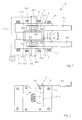
Figur 1 eine Draufsicht auf eine erfindungsgemässe Vorrichtung zur in situ Charakterisierung der Qualitätsparameter und der Eigenschaften von anorganischen Bindemittelsystemen; -
Figur 2 eine Seitenansicht auf eine Wand der Vorrichtung gemässFigur 1 . - Eine erfindungsgemässe Vorrichtung P zur in situ Charakterisierung der Qualitätsparameter und der Eigenschaften von anorganischen Bindemittelsystemen weist gemäss
Figur 1 zwei Wände 1 und 2 auf, die in einem Abstand a voneinander angeordnet sind. Dieser Abstand a wird von Distanzhülsen 3 bestimmt, die jeweils einem Schraubenbolzen 4 aufgeschoben sind. Vier derartige Schraubenbolzen 4 durchsetzen jeweils die Wände 1 und 2, wobei auf aus den Wänden 1 und 2 (nicht mehr dargestellte) herausragende Enden des Schraubenbolzens 4 Rändelmuttern 5.1 bzw. 5.2 aufgeschraubt sind. - Jede Wand 1 bzw. 2 besitzt eine in
Figur 2 gestrichelt bzw. erkennbare Stufenausnehmung 6. Ein von oben gesehen erster Teil der Stufenausnehmung 6 ist als eine flache Führung 7.1 bzw. 7.2 für einen Schieber 8.1 bzw. 8.2 ausgebildet. Mit diesem Schieber 8.1 bzw. 8.2 kann die Stufenausnehmung 6 insgesamt verschlossen werden. - An die flache Führung 7.1 bzw. 7.2 schliesst ein Trichterschacht 9.1 bzw. 9.2 an, der in eine ovale Kammer 10.1 bzw. 10.2 übergeht. Dies ovale Kammer 10.1 bzw. 10.2 durchbricht in dieser ovalen Form auch die Wand 1 bzw. 2 nach aussen hin und sogar eine Platte 11.1 bzw. 11.2, welche in die Wand 1 bzw. 2 eingelassen ist. Allerdings wird die Kammer 10.1 bzw. 10.2 von einer Membran 12 überdeckt, welche zwischen der Platte 11.1 bzw. 11.2 und der Wand 1 bzw. 2 eingespannt ist. Diese Membran 12 kann bei Bedarf auch ausgetauscht werden, wozu vier Rändelmuttern 13.1 - 13.4 gelöst werden, welche auf Schraubenbolzen 14 aufsitzen, die wiederum durch die Wand 1 bzw. 2 hindurchgeführt sind.
- An die Kammer 10.1 bzw. 10.2 schliesst eine Schall-Sonde 15.1 bzw.15.2 an, die über eine entsprechende Verbindung 16.1 bzw. 16.2 mit einer Auswerteeinheit 17 in Verbindung steht.
- Zwischen den beiden Wänden 1 und 2 ist ein U-förmiges Aufnahmeelement 18 eingesetzt, welches bevorzugt aus einem Schaumstoff besteht. Dieses Aufnahmeelement 18 dient der Aufnahme eines zu untersuchenden Bindemittelsystems, weshalb es von der Festigkeit her geeignet sein muss, dieses Bindemittelsystem aufzunehmen und zu halten. Andererseits muss es elastisch genug sein, damit es abdichtend zwischen den beiden Wänden 1 und 2 eingespannt werden kann. Aus diesem Grunde muss auch eine Breite des Aufnahmeelementes 18 mit einer Länge der Distanzhülse 3 abgestimmt werden, sodass es zu einem geeigneten Einspannen des Aufnahmeelementes 18 zwischen den beiden Wänden 1 und 2 kommt.
- Die Funktionsweise der vorliegenden Erfindung ist folgende:
- Zunächst werden die beiden Wände 1 und 2 aufeinander festgelegt, um die Schall-Sonden 15.1 und 15.2 zu kalibrieren und die Auswerteeinheit 17 mit den entsprechenden Signalen zu füttern. Die beiden Kammern 10.1 und 10.2 sind mit Gel gefüllt und die entsprechenden Stufenausnehmungen 6.1 bzw. 6.2 durch die Schieber 8.1 bzw. 8.2 verschlossen.
- Nach dieser Kalibrierung werden die beiden Wände 1 und 2 durch die entsprechenden Schraubenbolzen 4 verbunden und der Abstand a durch die Distanzhülsen 3 erzeugt. Dabei wird bereits das Aufnahmeelement 18 zwischen die beiden Wände 1 und 2 eingesetzt bzw. eingespannt.
- Nunmehr kann ein zu untersuchendes Bindemittelsystem in das Aufnahmeelement 18 eingefüllt werden. Dieses Bindemittelsystem härtet aus, wobei nach vorgegebenen Zeitspannen Messungen mittels der Schall-Sonden 15.1 und 15.2 durchgeführt werden, um beispielsweise eine erreichte Druckfestigkeit des Bindemittelsystems in dem Aufnahmeelement 18 zu überprüfen. Im Rahmen der Erfindung ist es dabei wesentlich, dass ein Schwinden des Bindemittelsystems in dem Aufnahmeelement 18 durch Nachfliessen von Gel ausgeglichen wird, welches die Membran 12.1 bzw. 12.2 gegen das schwindende Bindemittelsystem drückt. Der Trichterschacht 9.1 bzw. 9.2 dient dabei als Vorratsraum für das nachfliessende Gel.
- Die Membranen 12.1 bzw. 12.2 bestehen bevorzugt aus einem Kunststoff und besitzen eine Dicke von weniger als 2 mm, bevorzugt von weniger als 1 mm. Beim Schwinden des Bindemittelsystems folgen die Membranen unter dem Druck des Gels, sodass sie permanent in Kontakt mit dem Bindemittelsystem bleiben. Hierdurch wird eine Übertragung der Schall-Sonden 15.1 bzw. 15.2 nicht unterbrochen, das heisst, es befindet sich weder Luft zwischen der Membran und dem zu untersuchenden Bindemittelsystems noch zwischen der Membran und dem Gel.
- Das erfindungsgemässe Verfahren kann z. Bsp. bei der Untersuchung der Druckfestigkeit von Beton angewendet werden. Nach der oben beschriebenen Kalibrierung der Schall-Sonden 15.1 und 15.2 und dem Abgleich durch die Auswerteeinheit 17, wird Beton in das Aufnahmeelement 18 gefüllt. Danach wird 28 Tage abgewartet, um die 28-Tage-Druckfestigkeit des Betons durch Laufzeitmessung von Schall und durch Auswertung dieser Laufzeitmessung in der Auswerteeinheit 17 zu ermitteln. Nach einer vorgegebenen Zeitspanne, beispielsweise einem Jahr, kann nochmals eine Messung durchgeführt werden, um eine weitere Druckfestigkeit zu ermitteln. Das Schwinden des Betons wird durch Nachfliessen von Gel und dem Nachdrücken der Membran 12. 1 bzw. 12.2 beim Schwinden des Betons ausgeglichen.
Bezugszeichenliste 1 Wand 34 67 2 Wand 35 68 3 Distanzhülse 36 69 4 Schraubenbolzen 37 70 5 Rändelmutter 38 71 6 Stufenausnehmung 39 72 7 Führung 40 73 8 Schieber 41 74 9 Trichterschacht 42 75 10 Kammer 43 76 11 Platte 44 77 12 Membran 45 78 13 Rändelmutter 46 79 14 Schraubenbolzen 47 15 Schall-Sonde 48 16 Verbindung 49 17 Auswerteeinheit 50 a Abstand 18 Aufnahmeelement 51 P Vorrichtung 19 52 20 53 21 54 22 55 23 56 24 57 25 58 26 59 27 60 28 61 29 62 30 63 31 64 32 65 33 66
Claims (12)
- Vorrichtung zur in situ Charakterisierung der Qualitätsparameter und/oder der Eigenschaften von anorganischen Bindemittelsystemen, insbesondere von aushärtbaren Gemischen, wobei sich das Bindemittelsystem in einem Aufnahmeelement (18) befindet, dem zumindest eine Wand (1, 2) mit einer Sonde (15.1, 15.2) zugeordnet ist, wobei zwischen dem Bindemittelsystem und der Sonde (15.1, 15.2) eine Kammer (10.1, 10.2) für ein Kontaktmaterial vorgesehen ist und eine Membran (12.1, 12.2) das Bindemittelsystem von dem Kontaktmaterial trennt,
dadurch gekennzeichnet,
dass die Membran bei einem Schwinden des Bindemittelsystems diesem folgt. - Vorrichtung zur in situ Charakterisierung der Qualitätsparameter und/oder der Eigenschaften von anorganischen Bindemittelsystemen, insbesondere von aushärtbaren Gemischen, wobei sich das Bindemittelsystem in einem Aufnahmeelement (18) befindet, dem zumindest eine Wand (1, 2) mit einer Sonde (15.1, 15.2) zugeordnet ist, wobei zwischen dem Bindemittelsystem und der Sonde (15.1, 15.2) eine Kammer (10.1, 10.2) für ein Kontaktmaterial vorgesehen ist und eine Membran (12.1, 12.2) das Bindemittelsystem von dem Kontaktmaterial trennt, dadurch gekennzeichnet, dass die Membran aus einem feinen Netz besteht.
- Vorrichtung zur in situ Charakterisierung der Qualitätsparameter und/oder der Eigenschaften von anorganischen Bindemittelsystemen, insbesondere von aushärtbaren Gemischen, wobei sich das Bindemittelsystem in einem Aufnahmeelement (18) befindet, dem zumindest eine Wand (1, 2) mit einer Sonde (15.1, 15.2) zugeordnet ist, wobei zwischen dem Bindemittelsystem und der Schall-Sonde (15.1, 15.2) eine Kammer (10.1, 10.2) für ein Kontaktmaterial vorgesehen ist und eine Membran (12.1, 12.2) das Bindemittelsystem von dem Kontaktmaterial trennt, dadurch gekennzeichnet, dass der Schall-Sonde (15.1, 15.2) eine Pulserkarte für den Einsatz eines Pulsgebers für die Sonde zugeordnet ist.
- Vorrichtung zur in situ Charakterisierung der Qualitätsparameter und/oder der Eigenschaften von anorganischen Bindemittelsystemen, insbesondere von aushärtbaren Gemischen, wobei sich das Bindemittelsystem in einem Aufnahmeelement (18) befindet, dem zumindest eine Wand (1, 2) mit einer Sonde (15.1, 15.2) zugeordnet ist, wobei zwischen dem Bindemittelsystem und der Sonde (15.1, 15.2) eine Kammer (10.1, 10.2) für ein Kontaktmaterial vorgesehen ist und eine Membran (12.1, 12.2) das Bindemittelsystem von dem Kontaktmaterial trennt, dadurch gekennzeichnet, dass Bindemittelsystem von beiden Seiten her mit Ultraschall beaufschlagbar ist.
- Vorrichtung nach Anspruch 4, dadurch gekennzeichnet, dass die Sonden (15.1, 15.2) abwechselnd in ihrer Funktion als Schallgeber bzw. Schallaufnehmer austauschbar sind.
- Vorrichtung nach wenigstens einem der Ansprüche 1 bis 5, dadurch gekennzeichnet, dass die Membran mit dem Bindemittelsystem verbunden ist.
- Vorrichtung nach Anspruch 6, dadurch gekennzeichnet, dass die Membran mit dem Bindemittelsystem durch Kleben verbunden ist.
- Vorrichtung nach Anspruch 7, dadurch gekennzeichnet, dass die Membran zum Bindemittelsystem hin mit einem doppelseitigen Klebeband belegt ist.
- Vorrichtung nach wenigstens einem der Ansprüche 2 bis 8, dadurch gekennzeichnet, dass das Netz in einen Rahmen eingespannt ist.
- Vorrichtung nach wenigstens einem der Ansprüche 1 bis 9, dadurch gekennzeichnet, dass die Membran (12.1, 12.2) in einem Rahmen eingespannt ist.
- Vorrichtung nach wenigstens einem der Ansprüche 1 bis 10, dadurch gekennzeichnet, dass dem Bindemittelsystem und/oder dem Gel ein Temperaturfühler zugeordnet ist.
- Vorrichtung nach Anspruch 11, dadurch gekennzeichnet, dass Kalibrierkurven für unterschiedliche Temperaturen vorgesehen sind.
Applications Claiming Priority (2)
| Application Number | Priority Date | Filing Date | Title |
|---|---|---|---|
| DE102012101108 | 2012-02-10 | ||
| DE102012101944A DE102012101944A1 (de) | 2012-02-10 | 2012-03-08 | Vorrichtung zur in situ Charakterisierung der Qualitätsparameter und/oder der Eigenschaften von anorganischen Bindemittelsystemen |
Publications (3)
| Publication Number | Publication Date |
|---|---|
| EP2626699A2 true EP2626699A2 (de) | 2013-08-14 |
| EP2626699A3 EP2626699A3 (de) | 2013-09-04 |
| EP2626699B1 EP2626699B1 (de) | 2020-09-30 |
Family
ID=47664178
Family Applications (1)
| Application Number | Title | Priority Date | Filing Date |
|---|---|---|---|
| EP13153612.0A Not-in-force EP2626699B1 (de) | 2012-02-10 | 2013-02-01 | Vorrichtung zur in situ Charakterisierung der Qualitätsparameter und/oder der Eigenschaften von anorganischen Bindemittelsystemen |
Country Status (3)
| Country | Link |
|---|---|
| EP (1) | EP2626699B1 (de) |
| CN (1) | CN103245725B (de) |
| DE (1) | DE102012101944A1 (de) |
Citations (1)
| Publication number | Priority date | Publication date | Assignee | Title |
|---|---|---|---|---|
| DE102010060068A1 (de) | 2010-10-20 | 2012-04-26 | Mf Instruments Gmbh | Vorrichtung und Verfahren zu in situ Charakterisierung der Qualitätsparameter und/oder der Eigenschaften von anorganischen Bindemittelsystemen |
Family Cites Families (4)
| Publication number | Priority date | Publication date | Assignee | Title |
|---|---|---|---|---|
| NL63421C (de) * | 1942-09-30 | |||
| CO4810262A1 (es) * | 1998-09-11 | 1999-06-30 | Pato Marcos Ruben Bollati | Metodo para cuantificacion energetica de materiales compues- tos. . . . |
| US8197031B2 (en) * | 2009-05-22 | 2012-06-12 | Xerox Corporation | Fluid dispensing subassembly with polymer layer |
| EP2591353B1 (de) * | 2010-07-08 | 2014-09-10 | MF Instruments GmbH | Vorrichtung und verfahren zur in situ charakterisierung der qualitätsparameter und/oder der eigenschaften von anorganischen bindemittelsystemen |
-
2012
- 2012-03-08 DE DE102012101944A patent/DE102012101944A1/de not_active Withdrawn
-
2013
- 2013-02-01 EP EP13153612.0A patent/EP2626699B1/de not_active Not-in-force
- 2013-02-16 CN CN201310051389.8A patent/CN103245725B/zh not_active Expired - Fee Related
Patent Citations (1)
| Publication number | Priority date | Publication date | Assignee | Title |
|---|---|---|---|---|
| DE102010060068A1 (de) | 2010-10-20 | 2012-04-26 | Mf Instruments Gmbh | Vorrichtung und Verfahren zu in situ Charakterisierung der Qualitätsparameter und/oder der Eigenschaften von anorganischen Bindemittelsystemen |
Also Published As
| Publication number | Publication date |
|---|---|
| EP2626699A3 (de) | 2013-09-04 |
| EP2626699B1 (de) | 2020-09-30 |
| DE102012101944A1 (de) | 2013-08-14 |
| CN103245725A (zh) | 2013-08-14 |
| CN103245725B (zh) | 2019-02-05 |
Similar Documents
| Publication | Publication Date | Title |
|---|---|---|
| EP3298360B1 (de) | Verfahren, computerprogrammprodukt und vorrichtung zur ermittlung einer charakteristischen grösse zur bewertung einer messanordnung umfassend ein clamp-on-ultraschall-durchflussmessgerät und ein messrohr | |
| EP3534145B1 (de) | Fugenversuchsstand | |
| EP3004827A1 (de) | Messeinrichtung und verfahren zur ermittlung einer druckkarte | |
| WO2010026253A1 (de) | Impulsechoverfahren mittels gruppenstrahler und temperaturkompensation | |
| EP3266597B1 (de) | Verfahren zur herstellung eines faserverbundbauteils | |
| EP2490856A1 (de) | Prozessüberwachung zum hochgeschwindigkeitsfügen | |
| DE60129966T2 (de) | Kollisionsprüfungsvorrichtung | |
| DE102013203238A1 (de) | Prüfvorrichtung und Verfahren zur Durchführung eines Drucktests | |
| DE102012101944A1 (de) | Vorrichtung zur in situ Charakterisierung der Qualitätsparameter und/oder der Eigenschaften von anorganischen Bindemittelsystemen | |
| EP2591353B1 (de) | Vorrichtung und verfahren zur in situ charakterisierung der qualitätsparameter und/oder der eigenschaften von anorganischen bindemittelsystemen | |
| DE10019497C2 (de) | Verfahren und Vorrichtung zur Messung der Wickelhärte einer Papierrolle | |
| AT520557A4 (de) | Verfahren zur Ermittlung eines korrigierten Werts für die viskositätsabhängige Schallgeschwindigkeit in einem zu untersuchenden Fluid | |
| DE2642650A1 (de) | Verfahren und vorrichtung zur oberflaechenpruefung mit ultraschall | |
| DE102024121270A1 (de) | System und Verfahren zur Ermittlung einer Verdichtung | |
| DE102014104914A1 (de) | Vorrichtung und Verfahren zur zerstörungsfreien Prüfung eines Prüflings mittels Ultraschall nach der Vergleichskörpermethode | |
| DE102010060068A1 (de) | Vorrichtung und Verfahren zu in situ Charakterisierung der Qualitätsparameter und/oder der Eigenschaften von anorganischen Bindemittelsystemen | |
| DE102015206225B4 (de) | Vorrichtung, verfahren und system zum prüfen eines schallwandlers | |
| DE60218001T2 (de) | Verfahren und Vorrichtung zur Messung einer Materialeigenschaft | |
| EP2238443B1 (de) | Vorrichtung und Verfahren zur zerstörungsfreien Prüfung eines Prüflings mittels Ultraschall-TOFD-Technik | |
| DE1573558C3 (de) | Verfahren zur zerstörungsfreien Prüfung von Blechen und Bändern mit Ultraschall | |
| DE102013108568A1 (de) | Verfahren und Vorrichtung zur Ermittlung der Bauteildicke eines Faserverbundbauteils | |
| DE102012002359A1 (de) | Verfahren und Vorrichtung zur Überprüfung der Funktion einer Messkette aus optischen Dehnungssensoren | |
| DE102014108639A1 (de) | Verformungsanalyse | |
| DE102014101227A1 (de) | Vorrichtung und Verfahren zur zerstörungsfreien Prüfung eines Prüflings mittels Ultraschall nach der AVG-Methode | |
| EP2720021A2 (de) | Kraftmesseinrichtung |
Legal Events
| Date | Code | Title | Description |
|---|---|---|---|
| PUAL | Search report despatched |
Free format text: ORIGINAL CODE: 0009013 |
|
| PUAI | Public reference made under article 153(3) epc to a published international application that has entered the european phase |
Free format text: ORIGINAL CODE: 0009012 |
|
| AK | Designated contracting states |
Kind code of ref document: A2 Designated state(s): AL AT BE BG CH CY CZ DE DK EE ES FI FR GB GR HR HU IE IS IT LI LT LU LV MC MK MT NL NO PL PT RO RS SE SI SK SM TR |
|
| AX | Request for extension of the european patent |
Extension state: BA ME |
|
| AK | Designated contracting states |
Kind code of ref document: A3 Designated state(s): AL AT BE BG CH CY CZ DE DK EE ES FI FR GB GR HR HU IE IS IT LI LT LU LV MC MK MT NL NO PL PT RO RS SE SI SK SM TR |
|
| AX | Request for extension of the european patent |
Extension state: BA ME |
|
| RIC1 | Information provided on ipc code assigned before grant |
Ipc: G01N 33/38 20060101AFI20130731BHEP Ipc: G01N 29/00 20060101ALI20130731BHEP |
|
| 17P | Request for examination filed |
Effective date: 20140303 |
|
| RBV | Designated contracting states (corrected) |
Designated state(s): AL AT BE BG CH CY CZ DE DK EE ES FI FR GB GR HR HU IE IS IT LI LT LU LV MC MK MT NL NO PL PT RO RS SE SI SK SM TR |
|
| STAA | Information on the status of an ep patent application or granted ep patent |
Free format text: STATUS: EXAMINATION IS IN PROGRESS |
|
| 17Q | First examination report despatched |
Effective date: 20181205 |
|
| REG | Reference to a national code |
Ref country code: DE Ref legal event code: R079 Ref document number: 502013015163 Country of ref document: DE Free format text: PREVIOUS MAIN CLASS: G01N0033380000 Ipc: G01N0029024000 |
|
| RIC1 | Information provided on ipc code assigned before grant |
Ipc: G01N 33/38 20060101ALI20190909BHEP Ipc: G01N 29/024 20060101AFI20190909BHEP Ipc: G01N 29/032 20060101ALI20190909BHEP Ipc: G01N 29/22 20060101ALI20190909BHEP |
|
| GRAP | Despatch of communication of intention to grant a patent |
Free format text: ORIGINAL CODE: EPIDOSNIGR1 |
|
| STAA | Information on the status of an ep patent application or granted ep patent |
Free format text: STATUS: GRANT OF PATENT IS INTENDED |
|
| INTG | Intention to grant announced |
Effective date: 20191025 |
|
| GRAS | Grant fee paid |
Free format text: ORIGINAL CODE: EPIDOSNIGR3 |
|
| GRAA | (expected) grant |
Free format text: ORIGINAL CODE: 0009210 |
|
| STAA | Information on the status of an ep patent application or granted ep patent |
Free format text: STATUS: THE PATENT HAS BEEN GRANTED |
|
| AK | Designated contracting states |
Kind code of ref document: B1 Designated state(s): AL AT BE BG CH CY CZ DE DK EE ES FI FR GB GR HR HU IE IS IT LI LT LU LV MC MK MT NL NO PL PT RO RS SE SI SK SM TR |
|
| REG | Reference to a national code |
Ref country code: GB Ref legal event code: FG4D Free format text: NOT ENGLISH Ref country code: CH Ref legal event code: EP |
|
| REG | Reference to a national code |
Ref country code: AT Ref legal event code: REF Ref document number: 1319317 Country of ref document: AT Kind code of ref document: T Effective date: 20201015 |
|
| REG | Reference to a national code |
Ref country code: DE Ref legal event code: R096 Ref document number: 502013015163 Country of ref document: DE |
|
| REG | Reference to a national code |
Ref country code: IE Ref legal event code: FG4D Free format text: LANGUAGE OF EP DOCUMENT: GERMAN |
|
| PG25 | Lapsed in a contracting state [announced via postgrant information from national office to epo] |
Ref country code: FI Free format text: LAPSE BECAUSE OF FAILURE TO SUBMIT A TRANSLATION OF THE DESCRIPTION OR TO PAY THE FEE WITHIN THE PRESCRIBED TIME-LIMIT Effective date: 20200930 Ref country code: GR Free format text: LAPSE BECAUSE OF FAILURE TO SUBMIT A TRANSLATION OF THE DESCRIPTION OR TO PAY THE FEE WITHIN THE PRESCRIBED TIME-LIMIT Effective date: 20201231 Ref country code: SE Free format text: LAPSE BECAUSE OF FAILURE TO SUBMIT A TRANSLATION OF THE DESCRIPTION OR TO PAY THE FEE WITHIN THE PRESCRIBED TIME-LIMIT Effective date: 20200930 Ref country code: HR Free format text: LAPSE BECAUSE OF FAILURE TO SUBMIT A TRANSLATION OF THE DESCRIPTION OR TO PAY THE FEE WITHIN THE PRESCRIBED TIME-LIMIT Effective date: 20200930 Ref country code: BG Free format text: LAPSE BECAUSE OF FAILURE TO SUBMIT A TRANSLATION OF THE DESCRIPTION OR TO PAY THE FEE WITHIN THE PRESCRIBED TIME-LIMIT Effective date: 20201230 Ref country code: NO Free format text: LAPSE BECAUSE OF FAILURE TO SUBMIT A TRANSLATION OF THE DESCRIPTION OR TO PAY THE FEE WITHIN THE PRESCRIBED TIME-LIMIT Effective date: 20201230 |
|
| PG25 | Lapsed in a contracting state [announced via postgrant information from national office to epo] |
Ref country code: LV Free format text: LAPSE BECAUSE OF FAILURE TO SUBMIT A TRANSLATION OF THE DESCRIPTION OR TO PAY THE FEE WITHIN THE PRESCRIBED TIME-LIMIT Effective date: 20200930 Ref country code: RS Free format text: LAPSE BECAUSE OF FAILURE TO SUBMIT A TRANSLATION OF THE DESCRIPTION OR TO PAY THE FEE WITHIN THE PRESCRIBED TIME-LIMIT Effective date: 20200930 |
|
| REG | Reference to a national code |
Ref country code: NL Ref legal event code: MP Effective date: 20200930 |
|
| REG | Reference to a national code |
Ref country code: LT Ref legal event code: MG4D |
|
| PG25 | Lapsed in a contracting state [announced via postgrant information from national office to epo] |
Ref country code: LT Free format text: LAPSE BECAUSE OF FAILURE TO SUBMIT A TRANSLATION OF THE DESCRIPTION OR TO PAY THE FEE WITHIN THE PRESCRIBED TIME-LIMIT Effective date: 20200930 Ref country code: NL Free format text: LAPSE BECAUSE OF FAILURE TO SUBMIT A TRANSLATION OF THE DESCRIPTION OR TO PAY THE FEE WITHIN THE PRESCRIBED TIME-LIMIT Effective date: 20200930 Ref country code: PT Free format text: LAPSE BECAUSE OF FAILURE TO SUBMIT A TRANSLATION OF THE DESCRIPTION OR TO PAY THE FEE WITHIN THE PRESCRIBED TIME-LIMIT Effective date: 20210201 Ref country code: SM Free format text: LAPSE BECAUSE OF FAILURE TO SUBMIT A TRANSLATION OF THE DESCRIPTION OR TO PAY THE FEE WITHIN THE PRESCRIBED TIME-LIMIT Effective date: 20200930 Ref country code: RO Free format text: LAPSE BECAUSE OF FAILURE TO SUBMIT A TRANSLATION OF THE DESCRIPTION OR TO PAY THE FEE WITHIN THE PRESCRIBED TIME-LIMIT Effective date: 20200930 Ref country code: EE Free format text: LAPSE BECAUSE OF FAILURE TO SUBMIT A TRANSLATION OF THE DESCRIPTION OR TO PAY THE FEE WITHIN THE PRESCRIBED TIME-LIMIT Effective date: 20200930 Ref country code: CZ Free format text: LAPSE BECAUSE OF FAILURE TO SUBMIT A TRANSLATION OF THE DESCRIPTION OR TO PAY THE FEE WITHIN THE PRESCRIBED TIME-LIMIT Effective date: 20200930 |
|
| PG25 | Lapsed in a contracting state [announced via postgrant information from national office to epo] |
Ref country code: PL Free format text: LAPSE BECAUSE OF FAILURE TO SUBMIT A TRANSLATION OF THE DESCRIPTION OR TO PAY THE FEE WITHIN THE PRESCRIBED TIME-LIMIT Effective date: 20200930 Ref country code: IS Free format text: LAPSE BECAUSE OF FAILURE TO SUBMIT A TRANSLATION OF THE DESCRIPTION OR TO PAY THE FEE WITHIN THE PRESCRIBED TIME-LIMIT Effective date: 20210130 Ref country code: ES Free format text: LAPSE BECAUSE OF FAILURE TO SUBMIT A TRANSLATION OF THE DESCRIPTION OR TO PAY THE FEE WITHIN THE PRESCRIBED TIME-LIMIT Effective date: 20200930 Ref country code: AL Free format text: LAPSE BECAUSE OF FAILURE TO SUBMIT A TRANSLATION OF THE DESCRIPTION OR TO PAY THE FEE WITHIN THE PRESCRIBED TIME-LIMIT Effective date: 20200930 |
|
| PG25 | Lapsed in a contracting state [announced via postgrant information from national office to epo] |
Ref country code: SK Free format text: LAPSE BECAUSE OF FAILURE TO SUBMIT A TRANSLATION OF THE DESCRIPTION OR TO PAY THE FEE WITHIN THE PRESCRIBED TIME-LIMIT Effective date: 20200930 |
|
| REG | Reference to a national code |
Ref country code: DE Ref legal event code: R097 Ref document number: 502013015163 Country of ref document: DE |
|
| PLBE | No opposition filed within time limit |
Free format text: ORIGINAL CODE: 0009261 |
|
| STAA | Information on the status of an ep patent application or granted ep patent |
Free format text: STATUS: NO OPPOSITION FILED WITHIN TIME LIMIT |
|
| PG25 | Lapsed in a contracting state [announced via postgrant information from national office to epo] |
Ref country code: DK Free format text: LAPSE BECAUSE OF FAILURE TO SUBMIT A TRANSLATION OF THE DESCRIPTION OR TO PAY THE FEE WITHIN THE PRESCRIBED TIME-LIMIT Effective date: 20200930 |
|
| 26N | No opposition filed |
Effective date: 20210701 |
|
| PG25 | Lapsed in a contracting state [announced via postgrant information from national office to epo] |
Ref country code: MC Free format text: LAPSE BECAUSE OF FAILURE TO SUBMIT A TRANSLATION OF THE DESCRIPTION OR TO PAY THE FEE WITHIN THE PRESCRIBED TIME-LIMIT Effective date: 20200930 |
|
| REG | Reference to a national code |
Ref country code: BE Ref legal event code: MM Effective date: 20210228 |
|
| PG25 | Lapsed in a contracting state [announced via postgrant information from national office to epo] |
Ref country code: LU Free format text: LAPSE BECAUSE OF NON-PAYMENT OF DUE FEES Effective date: 20210201 Ref country code: IT Free format text: LAPSE BECAUSE OF FAILURE TO SUBMIT A TRANSLATION OF THE DESCRIPTION OR TO PAY THE FEE WITHIN THE PRESCRIBED TIME-LIMIT Effective date: 20200930 |
|
| PG25 | Lapsed in a contracting state [announced via postgrant information from national office to epo] |
Ref country code: SI Free format text: LAPSE BECAUSE OF FAILURE TO SUBMIT A TRANSLATION OF THE DESCRIPTION OR TO PAY THE FEE WITHIN THE PRESCRIBED TIME-LIMIT Effective date: 20200930 |
|
| PG25 | Lapsed in a contracting state [announced via postgrant information from national office to epo] |
Ref country code: IE Free format text: LAPSE BECAUSE OF NON-PAYMENT OF DUE FEES Effective date: 20210201 |
|
| PGFP | Annual fee paid to national office [announced via postgrant information from national office to epo] |
Ref country code: GB Payment date: 20220221 Year of fee payment: 10 Ref country code: CH Payment date: 20220221 Year of fee payment: 10 Ref country code: AT Payment date: 20220215 Year of fee payment: 10 |
|
| PG25 | Lapsed in a contracting state [announced via postgrant information from national office to epo] |
Ref country code: IS Free format text: LAPSE BECAUSE OF FAILURE TO SUBMIT A TRANSLATION OF THE DESCRIPTION OR TO PAY THE FEE WITHIN THE PRESCRIBED TIME-LIMIT Effective date: 20210130 |
|
| PGFP | Annual fee paid to national office [announced via postgrant information from national office to epo] |
Ref country code: FR Payment date: 20220221 Year of fee payment: 10 |
|
| PG25 | Lapsed in a contracting state [announced via postgrant information from national office to epo] |
Ref country code: BE Free format text: LAPSE BECAUSE OF NON-PAYMENT OF DUE FEES Effective date: 20210228 |
|
| PGFP | Annual fee paid to national office [announced via postgrant information from national office to epo] |
Ref country code: DE Payment date: 20220427 Year of fee payment: 10 |
|
| PG25 | Lapsed in a contracting state [announced via postgrant information from national office to epo] |
Ref country code: HU Free format text: LAPSE BECAUSE OF FAILURE TO SUBMIT A TRANSLATION OF THE DESCRIPTION OR TO PAY THE FEE WITHIN THE PRESCRIBED TIME-LIMIT; INVALID AB INITIO Effective date: 20130201 |
|
| PG25 | Lapsed in a contracting state [announced via postgrant information from national office to epo] |
Ref country code: CY Free format text: LAPSE BECAUSE OF FAILURE TO SUBMIT A TRANSLATION OF THE DESCRIPTION OR TO PAY THE FEE WITHIN THE PRESCRIBED TIME-LIMIT Effective date: 20200930 |
|
| REG | Reference to a national code |
Ref country code: DE Ref legal event code: R119 Ref document number: 502013015163 Country of ref document: DE |
|
| REG | Reference to a national code |
Ref country code: CH Ref legal event code: PL |
|
| REG | Reference to a national code |
Ref country code: AT Ref legal event code: MM01 Ref document number: 1319317 Country of ref document: AT Kind code of ref document: T Effective date: 20230201 |
|
| GBPC | Gb: european patent ceased through non-payment of renewal fee |
Effective date: 20230201 |
|
| PG25 | Lapsed in a contracting state [announced via postgrant information from national office to epo] |
Ref country code: LI Free format text: LAPSE BECAUSE OF NON-PAYMENT OF DUE FEES Effective date: 20230228 Ref country code: CH Free format text: LAPSE BECAUSE OF NON-PAYMENT OF DUE FEES Effective date: 20230228 Ref country code: AT Free format text: LAPSE BECAUSE OF NON-PAYMENT OF DUE FEES Effective date: 20230201 |
|
| PG25 | Lapsed in a contracting state [announced via postgrant information from national office to epo] |
Ref country code: GB Free format text: LAPSE BECAUSE OF NON-PAYMENT OF DUE FEES Effective date: 20230201 |
|
| PG25 | Lapsed in a contracting state [announced via postgrant information from national office to epo] |
Ref country code: GB Free format text: LAPSE BECAUSE OF NON-PAYMENT OF DUE FEES Effective date: 20230201 Ref country code: FR Free format text: LAPSE BECAUSE OF NON-PAYMENT OF DUE FEES Effective date: 20230228 Ref country code: DE Free format text: LAPSE BECAUSE OF NON-PAYMENT OF DUE FEES Effective date: 20230901 |
|
| PG25 | Lapsed in a contracting state [announced via postgrant information from national office to epo] |
Ref country code: MK Free format text: LAPSE BECAUSE OF FAILURE TO SUBMIT A TRANSLATION OF THE DESCRIPTION OR TO PAY THE FEE WITHIN THE PRESCRIBED TIME-LIMIT Effective date: 20200930 |
|
| PG25 | Lapsed in a contracting state [announced via postgrant information from national office to epo] |
Ref country code: MT Free format text: LAPSE BECAUSE OF FAILURE TO SUBMIT A TRANSLATION OF THE DESCRIPTION OR TO PAY THE FEE WITHIN THE PRESCRIBED TIME-LIMIT Effective date: 20200930 |
|
| PG25 | Lapsed in a contracting state [announced via postgrant information from national office to epo] |
Ref country code: TR Free format text: LAPSE BECAUSE OF FAILURE TO SUBMIT A TRANSLATION OF THE DESCRIPTION OR TO PAY THE FEE WITHIN THE PRESCRIBED TIME-LIMIT Effective date: 20200930 |