EP2626332A1 - Aeration of sludge with nozzles having specific diameter - Google Patents
Aeration of sludge with nozzles having specific diameter Download PDFInfo
- Publication number
- EP2626332A1 EP2626332A1 EP20120000900 EP12000900A EP2626332A1 EP 2626332 A1 EP2626332 A1 EP 2626332A1 EP 20120000900 EP20120000900 EP 20120000900 EP 12000900 A EP12000900 A EP 12000900A EP 2626332 A1 EP2626332 A1 EP 2626332A1
- Authority
- EP
- European Patent Office
- Prior art keywords
- gas
- fluid
- nozzle
- systems
- nozzle element
- Prior art date
- Legal status (The legal status is an assumption and is not a legal conclusion. Google has not performed a legal analysis and makes no representation as to the accuracy of the status listed.)
- Withdrawn
Links
Images


Classifications
-
- C—CHEMISTRY; METALLURGY
- C02—TREATMENT OF WATER, WASTE WATER, SEWAGE, OR SLUDGE
- C02F—TREATMENT OF WATER, WASTE WATER, SEWAGE, OR SLUDGE
- C02F3/00—Biological treatment of water, waste water, or sewage
- C02F3/02—Aerobic processes
- C02F3/12—Activated sludge processes
- C02F3/20—Activated sludge processes using diffusers
- C02F3/201—Perforated, resilient plastic diffusers, e.g. membranes, sheets, foils, tubes, hoses
-
- Y—GENERAL TAGGING OF NEW TECHNOLOGICAL DEVELOPMENTS; GENERAL TAGGING OF CROSS-SECTIONAL TECHNOLOGIES SPANNING OVER SEVERAL SECTIONS OF THE IPC; TECHNICAL SUBJECTS COVERED BY FORMER USPC CROSS-REFERENCE ART COLLECTIONS [XRACs] AND DIGESTS
- Y02—TECHNOLOGIES OR APPLICATIONS FOR MITIGATION OR ADAPTATION AGAINST CLIMATE CHANGE
- Y02W—CLIMATE CHANGE MITIGATION TECHNOLOGIES RELATED TO WASTEWATER TREATMENT OR WASTE MANAGEMENT
- Y02W10/00—Technologies for wastewater treatment
- Y02W10/10—Biological treatment of water, waste water, or sewage
Definitions
- the invention includes a method for the controlled charging of nozzle carrier FLUID elements or nozzle carrier GAS elements, in which a plurality of Utilizzed nozzle elements FLUID or nozzle elements GAS are used airtight on top, depending on the process step liquid or gaseous media Activation and operational optimization of sewage treatment and purification processes of municipal and industrial wastewater and sewage from sewage sludge and residue treatment, as well as from landfills in mechanical-biological or "batch" operated activated sludge plants, as well as to improve the water quality in flowing and standing natural and artificial waters , As well as a method for manufacturing a nozzle carrier FLUID element or nozzle carrier gas element to implement.
- An essential step in the biological degradation of wastewater constituents in sewage treatment plants is achieved in that in the activation process an oxygen enrichment by various methods such. coarse or fine bubble compressed air ventilation, as well as membrane and Keramikbelrangeer etc. is implemented.
- suitable microorganisms such as bacteria, threadlike algae, etc., as well as the Ummélzreae in sewage treatment plants, is currently permanently a very high energy consumption for the provision of electricity for operation of ventilation systems necessary.
- the object of the present invention is the overall technical costs for the construction, operation, maintenance and total energy consumption of activated sludge plants significantly reduce that can be reacted in the core idea according to the invention by a novel method with the features of claim 1 for feeding nozzle support systems for FLUID and GAS media in the activation systems and their technical implementation.
- DT-FLUID can by mixing a corresponding biodegradable reagent in the FLUID, as often used in sewage treatment plants acetic acid, via the coupling of a "flying" flushing hose on the feed system Perform minimal maintenance in the respective DT system.
- Another alternative to circulation and optimum mixing of the volume in the aeration tank is the ability to charge the DT-FLUID with a gas medium under higher pressure during the timed denitrification process, the DT-FLUID, via a spool-controlled short-circuit line between the MA-GAS and MA-FLUID. With this option, the forcibly resulting, much larger mushroom-like bubbles cause a vertical, grid-like mixing with less energy than is possible with the currently used circulating pumps.
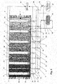
- Fig.1 a procedural plan of an aeration tank [3] on the pelvic floor [2] exemplified differently illustrated DT systems [14] namely DT-FLUID [8] and DT-GAS [9] are laid, which are necessary for procedural differentiated tasks in the activation process.
- the supply of the necessary gas media for feeding the DT-GAS [16] takes place in the GM converter [27], in the process due to a concentration of the air medium, for example, by pure oxygen or for the elimination of trace substances such. B. by ozone, can take place.
- the circulating pump [43] installed in the aeration tank [43] briefly conveys waste water from the activated sludge tank [3] via the recirculation line [42] to the FM converter [25], in which possibly an admixture of acetic acid to reduce fat in each DT -System [14] is added.
- the curved purge hose [40] to the FM converter [25] in Fig. 1 is connected here by way of example to a separate MA-FLUID [28] via a flushing hose coupling [41] so that a single DT-GAS [16] can be backwashed.
- Another alternative, not shown separately here, could also be done by coupling the flushing hose [40] directly to the FM converter [25].
Abstract
Description
Die Erfindung beinhaltet ein Verfahren zur gesteuerten Beschickung von Düsenträger-FLUID-Elementen bzw. Düsenträger-GAS-Elementen, in die oberseitig eine Vielzahl von verfahrensbdingten Düsenelementen-FLUID bzw. Düsenelementen-GAS luftdicht eingesetzt werden, um je nach Verfahrensschritt flüssige oder gasförmige Medien zur Aktivierung und Betriebsoptimierung von Klär- und Reinigungsprozessen von kommunalen und gewerblichindustriellen Abwässern und Abwässern aus der Klärschlamm- und Rückstandsbehandlung, sowie aus Deponien in mechanisch-biologischen bzw. "batch" betriebenen Belebungsanlagen, sowie zur Verbesserung der Gewässergüte in fließenden und stehenden natürlichen und künstlichen Gewässern, sowie ein Verfahren zur Fertigung eines Düsenträger-FLUID-Elementes bzw. Düsenträger-GAS-Elementes, umzusetzen. Ein wesentlicher Schritt beim biologischen Abbau von Abwasserinhaltsstoffen in den Kläranlagen wird dadurch erreicht, dass im Belebungsverfahren eine Sauerstoffanreicherung mittels unterschiedlichster Methoden wie z.B. grob- oder feinblasige Druckluftbelüftung, sowie Membran- und Keramikbelüfter usw. umgesetzt wird. Um den Eintrag von Sauerstoff zum aeroben Abbau mittels geeigneter Mikroorganismen, wie Bakterien, fadenartige Algen usw., sowie der Umwälzprozesse in den Kläranlagen zu ermöglichen, ist derzeit dauerhaft ein sehr hoher Energieaufwand für die Bereitstellung von elektrischem Strom zum Betrieb von Belüftungsanlagen notwendig. Wegen der steigenden Energiekosten und der politischen Vorgaben zur Reduktion des Ausstoßes klimaschädlicher Gase ist es nunmehr sinnvoll, Verfahren zu entwickeln, die es ermöglichen den Energieverbrauch von Kläranlagen und hierbei insbesondere von Belebungsanlagen dauerhaft zu minimieren und weiterhin auch alle notwendigen Schritte zu verfolgen die Bau-, Wartungs- und Betriebskosten der Gesamtanlagen zu reduzieren.The invention includes a method for the controlled charging of nozzle carrier FLUID elements or nozzle carrier GAS elements, in which a plurality of procedurized nozzle elements FLUID or nozzle elements GAS are used airtight on top, depending on the process step liquid or gaseous media Activation and operational optimization of sewage treatment and purification processes of municipal and industrial wastewater and sewage from sewage sludge and residue treatment, as well as from landfills in mechanical-biological or "batch" operated activated sludge plants, as well as to improve the water quality in flowing and standing natural and artificial waters , As well as a method for manufacturing a nozzle carrier FLUID element or nozzle carrier gas element to implement. An essential step in the biological degradation of wastewater constituents in sewage treatment plants is achieved in that in the activation process an oxygen enrichment by various methods such. coarse or fine bubble compressed air ventilation, as well as membrane and Keramikbelüfter etc. is implemented. In order to allow the entry of oxygen for aerobic degradation by means of suitable microorganisms, such as bacteria, threadlike algae, etc., as well as the Umwälzprozesse in sewage treatment plants, is currently permanently a very high energy consumption for the provision of electricity for operation of ventilation systems necessary. Due to the rising energy costs and the political requirements for reducing the emission of climate-damaging gases, it now makes sense to develop methods that allow the energy consumption of wastewater treatment plants and this particular of activation systems to permanently minimize and continue to follow all the necessary steps the construction, Reduce maintenance and operating costs of the entire system.
Aufgabe der vorliegenden Erfindung ist es, die technisch bedingten Gesamtkosten für den Bau, den Betrieb, die Wartung und den Gesamtenergieverbrauch von Belebungsanlagen wesentlich zu reduzieren, dass in der Kernidee erfindungsgemäß durch ein neuartiges Verfahren mit den Merkmalen des Anspruchs 1 zur Beschickung von Düsenträger-Systeme für FLUID und GAS- Medien in den Belebungsanlagen und deren technische Umsetzung rückschlüssig umgesetzt werden kann. The object of the present invention is the overall technical costs for the construction, operation, maintenance and total energy consumption of activated sludge plants significantly reduce that can be reacted in the core idea according to the invention by a novel method with the features of
Die Reduzierung des Energieverbrauches wird bei dem DT-GAS (DüsenTräger-GAS) im Wesentlichen dadurch erreicht, dass im Gegensatz zu den derzeit üblichen Membranbelüftern die systembedingten Druckverluste beim Gasdurchtritt aus den Membranschlitzen dauerhaft entfällt, weil das DE-GAS (DüsenElement-GAS) keinerlei Verschlussfunktion besitzt. Dieser Effekt ist auch beim DE-FLUID (DüsenElement-FLUID) nachvollziehbar. Die Größenordnung der austretenden Gasblasen aus dem DE-GAS ist insbesondere bei dem biologischen Abbauprozess der Schmutzstoffe für den Energieverbrauch von ausschlaggebender Bedeutung. Da größere Blasen mit einer entsprechend höheren Aufstiegsgeschwindigkeit aufsteigen, wird durch eine verkürzte Kontaktzeit der Gasblase eine verminderte Sauerstoffübertragung im Belebungsbecken erreicht, die noch dadurch verstärkt werden kann, wenn eine mögliche Koalierung einzelner aufsteigender Gasblasen zu stetig größeren Gasblasen entlang der Auftriebsstrecke stattfindet. Dieser Nachteil wird insbesondere bei dem DE-GAS unterbunden, weil im Regelfall der DE-Innendurchmesser ≤ 0,4 mm beträgt und durch den erfindungsgemäßen DE-Spitzenwinkel α ≥ 0 bzw. optimal 60° zur Horizontalen auf Grund eigener Versuche eine seitliche Verschiebung der austretenden Blase auftritt, die ein weitere Koalierung verhindert. Ein wesentlicher Nachteil der derzeitig verwendeten Belüfter ist darin zu sehen, dass verflüssigter Schlamm- sowie Fett oder auch Kalkanteile usw. aus dem Belebtschlamm in die Membranbelüfter bzw. Rohrbelüfter eindringen und Schlitze in den Membranen oder auch die gesamte Oberfläche zusetzen können. Die eingetragene Luft führt zur Verdunstung des eingetretenen Abwassers, hier durch werden jedoch die Festanteile aus dem Innenraum der rohr- oder tellerförmigen Belüfterträger nicht entfernt. Diese Problematik kann bei einer Versetzung der DE-Systeme, wenn sie mit ihrem DE-Sockel auf dem DT-U-Wannenboden aufsitzen nicht eintreten, da hierdurch eine Zwangsentleerung des Innenraumes im DT-Systeme nicht nur über die DE-Systeme sondern zusätzlich auch über die Anordnung eines auslaufseitigen DT-Überdruckventils umgesetzt wird, da die Einströmung von Gas oder Fluid hierbei immer hochverwirbelt über den DE-Einlauf in die DE-Systeme geleitet wird. Sollten Verkrustungen aus Belebtschlamm oder Fetten usw. z.B. in einem DT-FLUID auftreten, so kann ein solches DT-System durch Einmischung einer entsprechenden biologisch abbaubaren Reagenz im FLUID, wie vielfach auf Kläranlagen verwendete Essigsäure, über die Ankoppelung eines "fliegenden" Spülschlauchs am Zulaufsystem eine wartungsminimale Reinigung im jeweiligen DT-System bewirken. Eine weitere Alternative zur Umwälzung und optimalen Aufmischung des Volumens im Belebungsbecken ist die Möglichkeit, beim zeitgetaktete Denitrifikationsprozess, dem DT-FLUID über eine schiebergesteuerte Kurzschlussleitung zwischen dem MA-GAS und MA-FLUID den DT-FLUID unter höherem Druck mit einem Gasmedium zu beschicken. Bei dieser Option bewirken die zwangsweise entstehenden, wesentlich größeren pilzkopfartigen Blasen, eine vertikale, rasterflächig geartete Durchmischung mit weniger Energieaufwand, als dies mit den derzeit genutzten Umwälzpumpen ermöglicht wird..The reduction in energy consumption is achieved in the DT-GAS (nozzle carrier GAS) essentially by the fact that in contrast to the currently common Membranbelüftern the system-related pressure losses during gas passage from the membrane slots permanently omitted because the DE-GAS (nozzle element GAS) no Has lock function. This effect can also be traced with the DE-FLUID (nozzle element FLUID). The order of magnitude of the escaping gas bubbles from DE-GAS is of decisive importance, in particular in the biodegradation process of the contaminants for the energy consumption. As larger bubbles rise at a correspondingly higher rate of ascent, shortened contact time of the gas bubble results in decreased oxygen transfer in the aeration tank, which can be exacerbated by possible coalescing of individual rising gas bubbles into progressively larger gas bubbles along the buoyancy path. This disadvantage is in particular prevented in DE-GAS because, as a rule, the DE inner diameter is ≦ 0.4 mm and due to the inventive DE tip angle α ≥ 0 or optimally 60 ° to the horizontal on the basis of own experiments a lateral displacement of the exiting Bubble occurs, which prevents further Koalierung. A major disadvantage of the presently used aerators is the fact that liquefied sludge and fat or lime etc. penetrate from the activated sludge in the Membranbelüfter or Rohrbelüfter and can enforce slots in the membranes or the entire surface. The registered air leads to the evaporation of the waste water, here, however, the solid components from the interior of the tubular or plate-shaped fan carrier are not removed. This problem can not occur at a displacement of the DE systems when they sit with their DE-socket on the DT-U-bottom of the tank, as a result Forced emptying of the interior in the DT systems is implemented not only via the DE systems but also via the arrangement of an outlet side DT pressure relief valve, since the inflow of gas or fluid is always swirled over the DE inlet into the DE systems , If incrustations of activated sludge or fats, etc. occur eg in a DT-FLUID, such DT system can by mixing a corresponding biodegradable reagent in the FLUID, as often used in sewage treatment plants acetic acid, via the coupling of a "flying" flushing hose on the feed system Perform minimal maintenance in the respective DT system. Another alternative to circulation and optimum mixing of the volume in the aeration tank is the ability to charge the DT-FLUID with a gas medium under higher pressure during the timed denitrification process, the DT-FLUID, via a spool-controlled short-circuit line between the MA-GAS and MA-FLUID. With this option, the forcibly resulting, much larger mushroom-like bubbles cause a vertical, grid-like mixing with less energy than is possible with the currently used circulating pumps.
Es zeigt in
Aus dem Lageplan wird weiterhin ersichtlich, dass die Beschickung der einzelnen DT-FLUID [15] ausgehend vom Fluid-Medien Konverter [25] der Reihe nach über folgende Systemteile: Medien-Beckenverteiler-Fluid [33], handbetätigter Medienabzweig-Schieber [31], gesteuerter Medienabzweig-Schieber [30], Medien-Beckenverteiler-Fluid [33], handbetätigter Medienabzweig-Schieber [31], gesteuerter Medienabzweig-Schieber [30], Medienabzweig-Schlauch [32], Medienabzweiger-Fluid [28] zum DT-FLUID [15] erfolgt. Weiterhin ist zu erkennen, dass die in den jeweiligen Medienabzweiger-GAS [29] bzw. Medienabzweiger-FLUID [28] installierten gesteuerten Medienabzweigschieber [30] mittels eines Bus-Systems [4] mit einem SPS-System [39] verbunden sind und die vorgelagerten, handbetätigten Medienabzweigschieber [31] zur besseren Wartung genutzt werden. Da nicht auszuschließen ist, dass sich beim Betrieb der DT-Systeme [14] Belebtschlammflocken, Fette usw. in den DT-GAS [16] bzw. DT-FLUID [15] ablagern können, ist verfahrensgemäß eine Rückspülung der DT-Systeme [14] mit dem Abwasser des Belebungsbeckens [3] vorgesehen. Im Einzelnen kann die Umsetzung wie folgt erfolgen:It can also be seen from the site plan that the feed of the individual DT-FLUID [15] starting from the fluid-to-media converter [25] follows in sequence over the following system parts: Media basin distribution fluid [33], manually operated media branch gate valve [31] , controlled media branch slide [30], media basin distributor fluid [33], manually operated media branch slide [31], controlled media branch slide [30], media branch hose [32], media branch fluid [28] to the DT FLUID [15]. Furthermore, it can be seen that the controlled Medienabzweigschieber installed in the respective Medienabzweiger-GAS [29] and Medienabzweiger FLUID [28] [30] by means of a bus system [4] with a PLC system [39] and the upstream, hand-operated media slide valves [31] are used for better maintenance. Since it can not be ruled out that activated sludge flakes, fats, etc. can be deposited in the DT-GAS [16] or DT-FLUID [15] during operation of the DT systems [14], a backwashing of the DT systems [14 ] with the wastewater of the aeration tank provided. In detail, the implementation can be carried out as follows:
Die im Belebungsbecken [3] installierte Umwälzpumpe [43] fördert kurzzeitig mit erhöhtem Druck Abwasser aus dem Belebungsbecken [3] über die Umwälzleitung [42] zum FM-Konverter [25], in dem gegebenenfalls eine Zumischung von Essigsäure zum Fettabbau in de jeweiligen DT-System [14] beigemischt wird. Der gebogene Spülschlauch [40] zum FM-Konverter [25] in
Die Beschickung des Belebungsbeckens [3] mit Gasmedien zum biologischen Abbau von Abwasserinhaltsstoffen bzw. von Fluidmedien zur Volumenumwälzung des Belebungsbeckens [3] wird in
-
Fig. 1.1 zeigt einen funktionalen Längsschnitt durch ein Belebungsbecken [3], aus dem ersichtlich wird, wie die jeweilige Beschickungsanordnung der DT-GAS [16] bzw. den DT-FLUID [15], die auf dem Beckenboden [2] mit einem DT-Verbundabstand [23] angeordnet sind, nicht nur einzeln, sondern auch hier verdeutlicht im dreier Verbund vom Zulauf [44] in Fließrichtung [24] zum Ablauf [1] beschickt werden können, damit gegebenenfalls die Anzahl benötigter MA-Schieber [30,31] aus Kostengründen reduzierbar sind. -
Fig. 1 .2 veranschaulicht in einer unmaßstäblichen Querschnittskizze die verfahrensgemäße Vorgehensweise für eine gegebenenfalls notwendige Rückspülung eines DT-GAS [16] mit einem Fluid, dass beispielhaft aus dem Medien-Beckenverteiler-FLUID [33] über hintereinander angeordnete diverse Anlagensysteme wie folgt:- MA-FLUID [28] handbetätigter MA-Schieber [31], MA-FLUID [28], Spülschlauchkupplung [41], und "fliegenden" Spülschlauch [40], der am MA-FLUID [28] mittels Spülschlauchkupplung [41] an den MA-GAS [29] gekoppelt ist und damit die Rückspülung des DT-GAS [16] kurzzeitig unter erhöhter, gesteuerter Druckbeaufschlagung des Fluidmediums erfolgt. Ersichtlich und nachvollziehbar ist auch, dass durch die Vielzahl der DE-GAS [9] innerhalb des DT-GAS [16] eine große Verwirbelung des Fluidmediums eintritt, und damit eine zusätzliche großvolumige, schmutzfrachtbehaftete Entleerung über das DT-Überdruckventil [20] in Fließrichtung [24], erfolgen kann.
-
Fig. 2 veranschaulicht mittels einer 3D Zeichnung den Anschlussbereich des MA-GAS [29] an ein DT-GAS [16] mit seinem auf der DT-Wanne [21] verlegten, in diesem Falle seitlich verschweißten DT-Lochblech [17], in dem aus Gründen der vereinfachten Darstellung nur eine beispielhafte Anzahl von DE-GAS [9] dargestellt werden, die luftdicht in das hexagonale DT-Lochraster [18] im DT-Lochblech [17] versetzt sind. -
Fig. 2 .1 zeigt einen Schnitt durch das DT-GAS [16] gemäßFig. 2 , wobei ersichtlich wird, dass die DE-GAS [9] auf dem DT-U-Wannnenboden [22] mit dem DE-Sockel [11] aufsetzen, damit das zur Beschickung anstehende Gasmedium bzw. zu Spülzwecken benötigte Fluidmedium zwangsweise verwirbelt in den DE-Einlauf [7] eintritt und an der DE-Spitze [12], die mit einem DE-Spitzenwinkel α [13] ≥ 0 bzw. optimal 60° zur Horizontalen versehen ist, austritt. -
Fig. 2.2 zeigt eine Ansicht des erfindungsgemäßen DT-Systems [14] als DT-GAS [16], dass hier mit einigen DE-GAS [9] gemäß DT-Lochraster [18] bestückt ist, wobei das DT-Lochblech [17] und die DT-U-Wanne [21] seitlich mittels Verschraubungen [44] untereinander luftdicht verschraubt sind. -
Fig. 2 .3 zeigt einen Schnitt durch das DT-GAS [16] gemäßFig. 2.2 , wobei ersichtlich wird, dass die DE-GAS [9] auf dem DT-U-Wannnenboden [22] mit dem DE-Sockel [11] aufsetzen. Weiterhin erkennt man den MA-GAS [29] der luftdicht mit dem DT-Lochblech [17] verschweißt ist und die zugehörigen Verschraubungen [44] zwischen dem DT-Lochblech [17] und der DT-U-Wanne [21]. -
Fig. 2.4 zeigt eine Ansicht des erfindungsgemäßen DT-Systems [14] als DT-FLUID [15], dass hier mit einigen DE-FLUID [8] gemäß DT-Lochraster [18] bestückt ist, wobei das DT-Lochblech [17] und die DT-U-Wanne [21] seitlich verschweißt sind. -
Fig. 2.5 zeigt einen Schnitt durch das DT-FLUID [15] gemäßFig. 2.4 , wobei ersichtlich wird, dass die DE-FLUID [8] auf dem DT-U-Wannnenboden [22] mit dem DE-Sockel [11] aufsetzen. -
Fig. 3.1 zeigt eine Ansicht mit gestrichelten Schnittlinien des erfindungsgemäßen DE-Systems [5] als Spritzgussteil, wobei die DE-Spitze [12] mit seinem DE-Spitzenwinkel α [13] von ≥ 0 bzw. optimal 60° zur Horizontalen und dem mittig angeordneten DE-Innendurchmesser [10] erkennbar ist. Weiterhin wird ersichtlich, dass das DE-GAS [16] mit seinem DE-Sockel [11] auf dem DT-U-Wannnenboden [22] aufsitzt und der DE-Einlauf [7] verbindungstechnisch bis zur DE-Spitze [12] in Fließrichtung [24] über den DE-Innendurchmesser [10] der beschickbaren unterschiedlichen Medien GAS bzw. FLIUD gestrichelt verbunden ist. Das eingezeichnete DT-Lochblech [17] und der DT-U-Wannenboden [22] verdeutlichen, dass die notwendige luftdichte Verbindung im DT-Lochraster [18] mit dem jeweiligen DE-System [5] gewährleistet sein muss. -
Fig. 3.2 zeigt eine Ansicht des erfindungsgemäßen DE-Systems [5] hier DE-GAS [9] in kompletter Edelstahlausführung mit den ähnlichen Merkmalen wieFig. 3.1 . -
Fig. 3.3 zeigt eine Ansicht des erfindungsgemäßen DE-Systems [5] hier DE-GAS [9] in einer kombinierten Edelstahlausführung der DE-Spitze [12] unter einem DE-Spitzenwinkel α [13] von ≥ 0 bzw. optimal 60° zur Horizontalen und einem Spritzgussteil im Bereich zwischen DT-Lochblech [17] und der DT-U-Wannenboden [22], ansonsten mit den ähnlichen Merkmalen wieFig. 3.1 . -
Fig. 3.4 zeigt eine Ansicht des DE-Systems [5] hier DE-FLUID [8] in einer kompletten Edelstahlausführung mit einem erfindungsgemäß größeren DE-Innendurchmesser [10] bei dem die DE-Spitze [12] unter einem DE-Spitzenwinkel α [13] = 0° zur Horizontalen ausgebildet ist. Ansonsten gelten auch hier die ähnlichen Merkmale wie inFig. 3.1 .
-
Fig. 1.1 shows a functional longitudinal section through an aeration tank [3], which shows how the respective feed arrangement of the DT-GAS [16] or the DT-FLUID [15], which on the pelvic floor [2] with a DT composite distance [ 23] are arranged, not only individually, but also illustrated here in the three composite of the inlet [44] in the flow direction [24] can be fed to the outlet [1], so possibly the number of required MA slide [30,31] for cost reasons are reducible. -
Fig. 1 ,2 illustrates in a non-scale cross-sectional sketch of the procedure for an optionally necessary backwashing a DT-GAS [16] with a fluid, for example from the media basin distributor FLUID [33] on successively arranged various systems as follows:- MA-FLUID [28] Manually operated MA slide valve [31], MA-FLUID [28], flushing hose coupling [41], and "flying" flushing hose [40], which are connected to the MA-FLUID [28] by means of a flushing hose coupling [41] MA-GAS [29] is coupled and thus the backwashing of the DT-GAS [16] takes place briefly under increased, controlled pressurization of the fluid medium. It is also clear and comprehensible that due to the large number of DE-GAS [9] within the DT-GAS [16] a large fluidization of the fluid medium occurs, and thus an additional large-volume, dirt-laden emptying via the DT pressure relief valve [20] in the flow direction [24], can take place.
-
Fig. 2 illustrates by means of a 3D drawing the connection area of the MA-gas [29] to a DT-GAS [16] with his on the DT-well [21] laid, in this case laterally welded DT-perforated plate [17], in the reason of the simplified representation, only an exemplary number of DE-GAS [9] are shown, which are airtight offset in the hexagonal DT hole pattern [18] in the DT perforated plate [17]. -
Fig. 2 ,1 shows a section through the DT-GAS [16] according toFig. 2 , it can be seen that the DE-GAS [9] put on the DT-U-Wannnenboden [22] with the DE-socket [11], so that the pending for charging gas medium or required for flushing fluid medium forcibly swirled in the DE Inlet [7] and exits at the DE tip [12], which is provided with a DE tip angle α [13] ≥ 0 or optimally 60 ° to the horizontal. -
Fig. 2.2 shows a view of DT system according to the invention [14] as DT-GAS [16] that here with some DE-GAS [9] according to DT-hole pattern [18] is equipped, the DT-perforated plate [17] and the DT -U-tub [21] are bolted to each other airtight by means of fittings [44]. -
Fig. 2 ,3 shows a section through the DT-GAS [16] according toFig. 2.2 , it can be seen that the DE-GAS [9] put on the DT-U-Wannnenboden [22] with the DE-socket [11]. Furthermore, one recognizes the MA-GAS [29] which is airtight welded to the DT perforated plate [17] and the associated screw connections [44] between the DT perforated plate [17] and the DT-U pan [21]. -
Fig. 2.4 shows a view of the DT system according to the invention [14] as DT-FLUID [15], that here with some DE-FLUID [8] according to DT-hole pattern [18] is equipped, the DT-perforated plate [17] and the DT -U-tub [21] are welded laterally. -
Fig. 2.5 shows a section through the DT-FLUID [15] according toFig. 2.4 , it can be seen that the DE-FLUID [8] sit on the DT-U-Wannnenboden [22] with the DE-socket [11]. -
Fig. 3.1 shows a view with dashed lines of the DE system according to the invention [5] as an injection molded part, wherein the DE tip [12] with its DE tip angle α [13] of ≥ 0 or optimally 60 ° to the horizontal and the centrally arranged DE Inner diameter [10] is recognizable. Furthermore, it can be seen that the DE-GAS [16] with its DE socket [11] rests on the DT-U-Wannnenboden [22] and the DE inlet [7] connection technology to the DE-tip [12] in the flow direction [24] is connected in dashed lines via the DE inner diameter [10] of the chargeable different media GAS or FLIUD. The drawn DT perforated plate [17] and the DT-U bottom [22] illustrate that the necessary airtight connection in the DT perforated grid [18] must be ensured with the respective DE system [5]. -
Fig. 3.2 shows a view of the DE system according to the invention [5] here DE-GAS [9] in complete stainless steel design with the similar features asFig. 3.1 , -
Fig. 3.3 shows a view of the DE system according to the invention [5] here DE-GAS [9] in a combined stainless steel version of DE tip [12] at a DE tip angle α [13] of ≥ 0 or optimally 60 ° to the horizontal and a Injection molded part in the area between the DT perforated plate [17] and the DT-U bottom [22], otherwise with the similar features asFig. 3.1 , -
Fig. 3.4 shows a view of the DE system [5] here DE-FLUID [8] in a complete stainless steel design with an inventively larger DE inner diameter [10] in which the DE tip [12] at a DE tip angle α [13] = 0 ° to the horizontal is formed. Otherwise, the similar features apply here as inFig. 3.1 ,
Claims (5)
dass die DE-Innendurchmesser [10] ≤ 0,4 mm bei den DE-Gas [9] betragen, um möglichst schon bei geringsten Gasdrücken minimalvolumige Gasblasen zu erzeugen und weiterhin die DE-Innendurchmesser [10] im Regelfall zwischen ≥ 1,00 und 4,00 mm bei den DE-Fluid [8] zur besseren Aufmischung und Volumenumwälzung der Belebungsbecken [3] ausgebildet werden, wobei die DE-Spitze [12] der DE-GAS [9] zur feineren Gasblasenbildung einen DE-Spitzenwinkel α [13] von ≥ 0 bzw. optimal 60° zur Horizontalen besitzen und die DT-FLUID [15] zur Bedüsungsoptimierung mit einem DE-Spitzenwinkel α [13] = 0° ausgestattet ist und weiterhin zur Zwangsentwässerung durch eventuell eintretendes Abwasser aus dem Belebungsbecken [3] eine Zwangsentleerung der DT-Systeme [14; 15; 16] dadurch ermöglicht wird, dass der DE-Sockel [11] mit seinem anschließenden DE-Einlauf [7] auf dem jeweiligen DT-U-Wannenboden [22] aufsitzt. Method for the controlled charging of general DT systems [14], in particular DT-GAS [16] or DT-FLUID [15], with a top-side DT perforated plate [17], in the process, a corresponding number of general DE Depending on the process step, gaseous or liquid media for activating and optimizing the operation of waste water treatment processes in mechanically-biological or "batch" activated sludge tanks [3] are added to systems [5], in particular DE-GAS [9] or DE-FLUID [8]. , as well as to implement methods for the process-dependent production of differently designed DT systems [14] and associated DE systems [5], characterized
that the DE internal diameters [10] ≤ 0.4 mm for the DE gas [9] in order to produce gas bubbles as small as possible even at very low gas pressures and furthermore the DE inner diameter [10] usually between ≥ 1.00 and 4.00 mm for the DE fluid [8] for better mixing and volume circulation of the aeration tanks [3] are formed, wherein the DE tip [12] of the DE gas [9] for finer gas bubble formation a DE tip angle α [13 ] of ≥ 0 or optimally 60 ° to the horizontal and the DT -FLUID [15] is equipped for nozzle optimization with a DE tip angle α [13] = 0 ° and furthermore for forced drainage through any incoming wastewater from the aeration tank [3] Forced emptying of DT systems [14; 15; 16] is thereby made possible that the DE- socket [11] with its subsequent DE inlet [7] on the respective DT -U-bottom [22] is seated.
Priority Applications (1)
| Application Number | Priority Date | Filing Date | Title |
|---|---|---|---|
| EP20120000900 EP2626332A1 (en) | 2012-02-11 | 2012-02-11 | Aeration of sludge with nozzles having specific diameter |
Applications Claiming Priority (1)
| Application Number | Priority Date | Filing Date | Title |
|---|---|---|---|
| EP20120000900 EP2626332A1 (en) | 2012-02-11 | 2012-02-11 | Aeration of sludge with nozzles having specific diameter |
Publications (1)
| Publication Number | Publication Date |
|---|---|
| EP2626332A1 true EP2626332A1 (en) | 2013-08-14 |
Family
ID=45654967
Family Applications (1)
| Application Number | Title | Priority Date | Filing Date |
|---|---|---|---|
| EP20120000900 Withdrawn EP2626332A1 (en) | 2012-02-11 | 2012-02-11 | Aeration of sludge with nozzles having specific diameter |
Country Status (1)
| Country | Link |
|---|---|
| EP (1) | EP2626332A1 (en) |
Citations (3)
| Publication number | Priority date | Publication date | Assignee | Title |
|---|---|---|---|---|
| EP0383648A1 (en) * | 1989-02-06 | 1990-08-22 | Societe D'amenagement Urbain Et Rural | Apparatus for distributing and diffusing gas in a liquid containing or not granular material, and bioreactor provided with such apparatus |
| EP0698407A1 (en) * | 1994-08-26 | 1996-02-28 | Sulzer Chemtech AG | Waste water treatment reactor with a partition containing nozzles |
| EP2000604A1 (en) | 2007-06-06 | 2008-12-10 | Manfred Weikopf | Method for qualitative and quantitative waste water control in sewer emergency outlets |
-
2012
- 2012-02-11 EP EP20120000900 patent/EP2626332A1/en not_active Withdrawn
Patent Citations (3)
| Publication number | Priority date | Publication date | Assignee | Title |
|---|---|---|---|---|
| EP0383648A1 (en) * | 1989-02-06 | 1990-08-22 | Societe D'amenagement Urbain Et Rural | Apparatus for distributing and diffusing gas in a liquid containing or not granular material, and bioreactor provided with such apparatus |
| EP0698407A1 (en) * | 1994-08-26 | 1996-02-28 | Sulzer Chemtech AG | Waste water treatment reactor with a partition containing nozzles |
| EP2000604A1 (en) | 2007-06-06 | 2008-12-10 | Manfred Weikopf | Method for qualitative and quantitative waste water control in sewer emergency outlets |
Similar Documents
| Publication | Publication Date | Title |
|---|---|---|
| EP2321229A1 (en) | Waste water cleaning device comprising an anaerobic fixed bed filter and an electroflocculation cell | |
| DE102008020938A1 (en) | Method and device to optimize small sewage treatment-/small purification plants by avoiding/reducing discharge of sludge particles in the small sewage treatment and purification plants and/or other technical plants, comprise mammoth pump | |
| DE2210293A1 (en) | Process and device for the clarification of waste water | |
| DE60002691T2 (en) | DEVICE AND METHOD FOR MIXING, VENTILATION AND OXYGEN ENRICHMENT | |
| DE102008030809B4 (en) | Process and device for water recovery or for the purification of waste water | |
| DE202007006558U1 (en) | Device for introducing gases in fluids in water in the sense of a pressure ventilation system consisting an air supply line, comprises an aerator, and a hose line secured at the air supply lines using a tube clamp | |
| EP0996593A1 (en) | Method for removing biomass from a liquid by means of a reactor | |
| US6984325B1 (en) | Water and aqueous mix treatment using venturi discharge oxygen | |
| EP2424820B1 (en) | Device for clarifying sewage by means of dissolved air flotation, preferably on board ships | |
| DE2607963A1 (en) | METHOD AND DEVICE FOR GASIFYING LIQUIDS | |
| EP2626332A1 (en) | Aeration of sludge with nozzles having specific diameter | |
| EP0966404B1 (en) | Method and device for introducing oxygen into water or aqueous solutions | |
| DE4217491C1 (en) | Compact sewage treatment plant - comprising container with screen, pumps, aerators and two flotation devices, and second container aerobic reactor surrounded by anaerobic reactor | |
| DE102009017067A1 (en) | Plant for biological wastewater treatment | |
| DE3640964A1 (en) | Process and apparatus for introducing air and/or oxygen into activation tanks in waste water purification and for aerating lakes, ponds and rivers | |
| EP0102435B1 (en) | Process and apparatus for maintaning a fine gas dispersion in liquids | |
| EP1670723B1 (en) | Method for biologically purifying waste water | |
| EP1731487A1 (en) | Process and apparatus for the removal of a liquid from a basin | |
| EP1188721A1 (en) | Process and device for water treatment | |
| DE4434540C2 (en) | Process for aerobic high-performance wastewater treatment under pressure and strong dynamics and device for carrying out the process | |
| EP0770580A1 (en) | Process for the biological purification of waste water | |
| EP1884279B1 (en) | Method and device for feeding a gas into a fluid at supersonic velocity, and use of the method | |
| EP1610887B1 (en) | Method for regenerating water having a low-oxygen atmosphere | |
| DE102020210005A1 (en) | Process and device for the biological degradation of organic hydrocarbons in water | |
| DE202015107121U1 (en) | A water purification plant with vegetable zeolite |
Legal Events
| Date | Code | Title | Description |
|---|---|---|---|
| PUAI | Public reference made under article 153(3) epc to a published international application that has entered the european phase |
Free format text: ORIGINAL CODE: 0009012 |
|
| AK | Designated contracting states |
Kind code of ref document: A1 Designated state(s): AL AT BE BG CH CY CZ DE DK EE ES FI FR GB GR HR HU IE IS IT LI LT LU LV MC MK MT NL NO PL PT RO RS SE SI SK SM TR |
|
| AX | Request for extension of the european patent |
Extension state: BA ME |
|
| STAA | Information on the status of an ep patent application or granted ep patent |
Free format text: STATUS: THE APPLICATION IS DEEMED TO BE WITHDRAWN |
|
| 18D | Application deemed to be withdrawn |
Effective date: 20140215 |