EP0770580A1 - Process for the biological purification of waste water - Google Patents
Process for the biological purification of waste water Download PDFInfo
- Publication number
- EP0770580A1 EP0770580A1 EP19960116837 EP96116837A EP0770580A1 EP 0770580 A1 EP0770580 A1 EP 0770580A1 EP 19960116837 EP19960116837 EP 19960116837 EP 96116837 A EP96116837 A EP 96116837A EP 0770580 A1 EP0770580 A1 EP 0770580A1
- Authority
- EP
- European Patent Office
- Prior art keywords
- waste water
- guide tube
- gas
- fed
- reaction container
- Prior art date
- Legal status (The legal status is an assumption and is not a legal conclusion. Google has not performed a legal analysis and makes no representation as to the accuracy of the status listed.)
- Withdrawn
Links
Images
Classifications
-
- C—CHEMISTRY; METALLURGY
- C02—TREATMENT OF WATER, WASTE WATER, SEWAGE, OR SLUDGE
- C02F—TREATMENT OF WATER, WASTE WATER, SEWAGE, OR SLUDGE
- C02F3/00—Biological treatment of water, waste water, or sewage
- C02F3/02—Aerobic processes
- C02F3/12—Activated sludge processes
- C02F3/22—Activated sludge processes using circulation pipes
- C02F3/226—"Deep shaft" processes
-
- C—CHEMISTRY; METALLURGY
- C02—TREATMENT OF WATER, WASTE WATER, SEWAGE, OR SLUDGE
- C02F—TREATMENT OF WATER, WASTE WATER, SEWAGE, OR SLUDGE
- C02F3/00—Biological treatment of water, waste water, or sewage
- C02F3/02—Aerobic processes
- C02F3/12—Activated sludge processes
-
- Y—GENERAL TAGGING OF NEW TECHNOLOGICAL DEVELOPMENTS; GENERAL TAGGING OF CROSS-SECTIONAL TECHNOLOGIES SPANNING OVER SEVERAL SECTIONS OF THE IPC; TECHNICAL SUBJECTS COVERED BY FORMER USPC CROSS-REFERENCE ART COLLECTIONS [XRACs] AND DIGESTS
- Y02—TECHNOLOGIES OR APPLICATIONS FOR MITIGATION OR ADAPTATION AGAINST CLIMATE CHANGE
- Y02W—CLIMATE CHANGE MITIGATION TECHNOLOGIES RELATED TO WASTEWATER TREATMENT OR WASTE MANAGEMENT
- Y02W10/00—Technologies for wastewater treatment
- Y02W10/10—Biological treatment of water, waste water, or sewage
Definitions
- the invention relates to a method for the biological purification of waste water, in which the waste water and gas are fed to a reaction container containing microorganisms, in which at least one guide tube open at both ends is arranged with a vertical axis and at a distance from the bottom of the reaction container, and at which the mixture of waste water and gas is moved in the reaction vessel in a circuit leading through the guide tube (EP 0 130 499 B1).
- biomass-water mixture in a biological treatment of wastewater, organic pollutants from microorganisms - hereinafter referred to as "biomass" - are converted into harmless substances using oxygen.
- the wastewater is cleaned by gassing a biomass-water mixture in a reaction vessel, to which wastewater and gas are continuously fed and a comparable amount of the biomass-water mixture is removed.
- “Gas” means air, oxygen-enriched air or pure oxygen gas.
- DE 40 12 300 A1 describes a device for the biological purification of waste water in a closed reactor.
- a mixture of waste water, an oxygen-containing gas and biomass is fed to an inner flow guide tube of the reactor via a two-component nozzle, in the lower region in the position of use.
- a partial flow of the wastewater to be treated is injected into the annular space between the flow guide tube and the wall of the reactor.
- Part of the treated mixture is continuously fed into a separate mixing and degassing vessel.
- loop reactors are vertically arranged, cylindrical containers, in the interior of which there is an additional guide tube open on both sides with a vertical axis.
- loop reactor When this loop reactor is operated, a loop flow occurs around the guide tube with a mixture of liquid and gas. Advantages of such a loop flow are a relatively homogeneous flow of the two phases and the associated good transfer of the oxygen required for wastewater treatment from the gas into the liquid.
- the gas is above inserted into the guide tube so that it runs through a complete loop at least once before it can exit the reaction vessel.
- a high energy input through the liquid supplied to the guide tube is necessary so that the gas supplied and broken up into bubbles is transported downward with the loop flow against its ascending movement.
- the invention has for its object to develop the above-described method so that the energy consumption is reduced with improved mass transfer.
- This object is achieved according to the invention in that the wastewater is fed to the guide tube at the upper end in the position of use, while the gas is separated therefrom at at least two, at different heights and in the direction of flow of the pressurized wastewater behind its entry region into the guide tube is initiated into the same.
- the gas is fed to the guide tube at points which are downstream of the point at which the waste water is fed in the flow direction of the waste water introduced, for example by means of a pump. Due to this spatial separation of the feed points of wastewater and gas and a suitable distribution of the total of the gas introduced into its feed points, the gas is carried along with the downward movement of the wastewater or the liquid present in the guide tube even without a large energy input. This is especially true when the majority of the total gas to be introduced is fed into the lower area of the guide tube. The gas is then carried almost directly by the liquid emerging from the guide tube at the bottom. The strong swirling of the liquid during the transition from the guide tube into the jacket space surrounding the same ensures good gas dispersion. A separate dispersing device, such as. B.
- a ring distributor or a diaphragm distributor is thus omitted.
- the principle of the mammoth pump is used, which minimizes the energy required to maintain the loop flow.
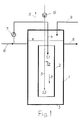
- a guide tube 2 with a vertical axis is arranged in a reaction vessel 1.
- the guide tube 2 is open at both ends. Its lower end has a sufficient distance from the bottom 3 of the reaction container 1 so that the liquid present in the same can be moved in a circuit leading through the guide tube 2.
- the liquid is a mixture of biomass and water.
- the wastewater to be cleaned is fed to the guide tube 2 via a pipeline 4. It enters guide tube 2 at location S1. Gas is also introduced into the guide tube 2 via at least one pipeline 5 and exits at points S2 and S3.
- the locations S1, S2 and S3 are spatially separated from one another.
- the positions S2 and S3 lie in the flow direction of the waste water in the guide pipe 2, indicated by the arrow P, behind the position S1. Deviating from the drawing, the gas could also be brought to points S2 and S3 via two separate feed lines.
- the method according to the invention works, for example, as follows:
- the wastewater (raw wastewater) to be cleaned, coming from a line 6, is fed via the pipeline 4 together with the liquid removed from the reaction container 1 to the guide tube 2 of the reaction container 1. If the speed of this liquid is sufficient, which can be adjusted by means of a pump 7, a loop flow is established around the guide tube 2.
- the cleaned waste water leaves the reaction vessel 1 together with Biomass via a line 8. Waste water and biomass are separated from one another in a downstream device, not shown here. The majority of the biomass is returned to reaction vessel 1 via a line 9. The rest of the biomass is removed as excess sludge.
- the oxygen required for wastewater treatment is introduced as gas, usually air or also enriched or pure oxygen gas, via the pipeline 5 into the guide tube 2 of the reaction container 1.
- the pipeline 5 can be inserted into the guide tube 2 from above, but also laterally.
- the mouth of the pipeline 5 is in the lower region of the guide tube 2, expediently in the lower fifth of the same.
- the gas is more or less compressed by means of a pump 10.
- the gas is dispersed at point S2 by the shearing action of the wastewater escaping at point S1 and at point S3 through the 180 degree deflection of the liquid at the lower end of the guide tube 2.
Abstract
Description
Die Erfindung bezieht sich auf ein Verfahren zum biologischen Reinigen von Abwasser, bei welchem das Abwasser und Gas einem Mikroorganismen enthaltenden Reaktionsbehälter zugeführt werden, in dem mindestens ein an beiden Enden offenes Leitrohr mit vertikaler Achse und mit Abstand zum Boden des Reaktionsbehälters angeordnet ist, und bei welchem das Gemisch aus Abwasser und Gas in dem Reaktionsbehälter in einem durch das Leitrohr führenden Kreislauf bewegt wird (EP 0 130 499 B1).The invention relates to a method for the biological purification of waste water, in which the waste water and gas are fed to a reaction container containing microorganisms, in which at least one guide tube open at both ends is arranged with a vertical axis and at a distance from the bottom of the reaction container, and at which the mixture of waste water and gas is moved in the reaction vessel in a circuit leading through the guide tube (EP 0 130 499 B1).
Bei der biologischen Reinigung von Abwasser werden organische Schadstoffe von Mikroorganismen - im folgenden als "Biomasse" bezeichnet - unter Verwendung von Sauerstoff in unschädliche Stoffe umgewandelt. Das Abwasser wird durch Begasen eines Biomasse-Wasser-Gemisches in einem Reaktionsbehälter gereinigt, dem kontinuierlich Abwasser und Gas zugeführt und eine vergleichbare Menge an Biomasse-Wasser-Gemisch entnommen werden. Unter "Gas" sollen Luft, mit Sauerstoff angereicherte Luft oder auch reines Sauerstoffgas verstanden werden.In the biological treatment of wastewater, organic pollutants from microorganisms - hereinafter referred to as "biomass" - are converted into harmless substances using oxygen. The wastewater is cleaned by gassing a biomass-water mixture in a reaction vessel, to which wastewater and gas are continuously fed and a comparable amount of the biomass-water mixture is removed. "Gas" means air, oxygen-enriched air or pure oxygen gas.
Im häuslichen Bereich, aber auch bei vielen industriellen Prozessen entstehen organisch beladene Abwässer. Für die Reinigung solcher Abwässer sind Verfahren zum Eliminieren der gelösten organischen Verbindungen auf aerobem Wege durch Mikroorganismen bekannt. Diese Verfahren werden meistens in flachen Belebungsbecken durchgeführt Die Nachteile derartiger Verfahren, wie Geruchsbelästigung der Umgebung aufgrund hoher Abluftmengen, hoher Lärmpegel, großer Platzbedarf sowie hohe Investitions- und Energiekosten, sind allgemein bekannt.Organically loaded wastewater is generated in the home, but also in many industrial processes. Methods for the elimination of the dissolved organic compounds by aerobic means by microorganisms are known for the purification of such waste water. These processes are mostly carried out in shallow activated sludge tanks. The disadvantages of such processes, such as odor nuisance in the environment due to high exhaust air quantities, high noise levels, large space requirements and high investment and energy costs, are generally known.
Es ist weiterhin bekannt, Abwasser in hohen zylindrischen Türmen ähnlich einer Blasensäule zu reinigen (DE-Z "Chemie-Ingenieur-Technik" 54 (1982), Nr. 11, Seiten 939 bis 952). Wegen der ungünstigen hydrodynamischen Verhältnisse und damit der relativ schlechten Stoffübergangsbedingungen von Blasensäulen ist deren Raumbelastung, das ist die auf das Volumen des Reaktionsbehälters und den Tag bezogene und in CSB gemessene Menge an Schmutzstoffen, vergleichsweise niedrig. Sie liegt bei etwa 1 kg CSB/m3d. Die Begasung erfolgt ausschließlich am Boden des jeweils eingesetzten Turmes, wodurch der spezifische Energiebedarf für dieses Verfahren relativ hoch ausfällt.It is also known to purify waste water in high cylindrical towers similar to a bubble column (DE-Z "Chemie-Ingenieur-Technik" 54 (1982), No. 11, pages 939 to 952). Because of the unfavorable hydrodynamic conditions and thus the relatively poor mass transfer conditions of bubble columns, their space load, i.e. the amount of contaminants related to the volume of the reaction container and the day and measured in COD, is comparatively low. It is about 1 kg COD / m 3 d. Fumigation takes place exclusively on the floor of the tower used, which means that the specific energy requirement for this process is relatively high.
In der DE 40 12 300 A1 ist eine Vorrichtung zum biologischen Reinigen von Abwasser in einem geschlossenen Reaktor beschrieben. Ein Gemisch aus Abwasser, einem Sauerstoff enthaltenden Gas und Biomasse wird über eine Zweistoffdüse einem inneren Strömungsleitrohr des Reaktors zugeführt, und zwar in dessen in Gebrauchslage unterem Bereich. Ein Teilstrom des zu behandelnden Abwassers wird in den Ringraum zwischen dem Strömungsleitrohr und der Wandung des Reaktors eingedüst. Ein Teil des behandelten Gemisches wird ständig in ein separates Misch- und Entgasungsgefäß geleitet. Durch die Einführung des Gemisches aus Abwasser, Gas und Biomasse an einer im unteren Bereich des Strömungsleitrohr liegenden Stelle enthält dasselbe in seinem oberen Bereich praktisch kein Gas. Es kann daher in diesem Bereich auch kein Sauerstoff in das Abwasser bzw. in das Gemisch übertragen werden. Trotz des mit dieser Vorrichtung gegebenen Schlaufenbetriebs ist daher die Stoffübertragung relativ schlecht.DE 40 12 300 A1 describes a device for the biological purification of waste water in a closed reactor. A mixture of waste water, an oxygen-containing gas and biomass is fed to an inner flow guide tube of the reactor via a two-component nozzle, in the lower region in the position of use. A partial flow of the wastewater to be treated is injected into the annular space between the flow guide tube and the wall of the reactor. Part of the treated mixture is continuously fed into a separate mixing and degassing vessel. By introducing the mixture of wastewater, gas and biomass at a point in the lower area of the flow guide tube, the upper area contains practically no gas. In this area, therefore, no oxygen can be transferred into the wastewater or into the mixture. Despite the loop operation provided by this device, the mass transfer is therefore relatively poor.
Mit dem eingangs beschrieben Verfahren nach der EP 0 130 499 B1 wird ein deutlich höherer Umsatz bei der Abwasserbehandlung erreicht. Es ergibt sich eine Raumbelastung von bis zu 70 kg CSB/m3d. Die bei diesem Verfahren eingesetzten Reaktionsbehälter werden als "Schlaufenreaktoren" bezeichnet. Hierbei handelt es sich um senkrecht angeordnete, zylindrische Behälter, in deren Innenraum zusätzlich ein an beiden Seiten offenes Leitrohr mit vertikaler Achse angebracht ist. Beim Betrieb dieses Schlaufenreaktors entsteht eine Schlaufenströmung um das Leitrohr mit einer Vermischung von Flüssigkeit und Gas. Vorteile einer solchen Schlaufenströmung sind eine verhältnismäßig homogene Strömung der beiden Phasen und die damit verbundene gute Übertragung des für die Abwasserreinigung benötigten Sauerstoffs aus dem Gas in die Flüssigkeit. Bei diesem bekannten Verfahren wird das Gas oben in das Leitrohr eingeführt, so daß es mindestens einmal eine vollständige Schlaufe durchläuft, ehe es aus dem Reaktionsbehälter austreten kann. Es ist jedoch ein hoher Energieeintrag durch die dem Leitrohr zugeführte Flüssigkeit erforderlich, damit das zugeführte und zu Blasen zerteilte Gas entgegen seiner Aufstiegsbewegung mit der Schlaufenströmung nach unten transportiert wird.With the method described at the outset according to EP 0 130 499 B1, a significantly higher conversion in wastewater treatment is achieved. This results in a space load of up to 70 kg COD / m 3 d. The reaction vessels used in this process are referred to as "loop reactors". These are vertically arranged, cylindrical containers, in the interior of which there is an additional guide tube open on both sides with a vertical axis. When this loop reactor is operated, a loop flow occurs around the guide tube with a mixture of liquid and gas. Advantages of such a loop flow are a relatively homogeneous flow of the two phases and the associated good transfer of the oxygen required for wastewater treatment from the gas into the liquid. In this known method, the gas is above inserted into the guide tube so that it runs through a complete loop at least once before it can exit the reaction vessel. However, a high energy input through the liquid supplied to the guide tube is necessary so that the gas supplied and broken up into bubbles is transported downward with the loop flow against its ascending movement.
Der Erfindung liegt die Aufgabe zugrunde, das eingangs geschilderte Verfahren so weiterzubilden, daß bei verbessertem Stoffaustausch der Energieaufwand vermindert wird.The invention has for its object to develop the above-described method so that the energy consumption is reduced with improved mass transfer.
Diese Aufgabe wird gemäß der Erfindung dadurch gelöst, daß das Abwasser dem Leitrohr am in Gebrauchslage oberen Ende zugeführt wird, während das Gas davon getrennt an mindestens zwei, in unterschiedlicher Höhe und in Strömungsrichtung des unter Druck eingebrachten Abwassers hinter dessen Eintrittsbereich in das Leitrohr liegenden Stellen in dasselbe eingeleitet wird.This object is achieved according to the invention in that the wastewater is fed to the guide tube at the upper end in the position of use, while the gas is separated therefrom at at least two, at different heights and in the direction of flow of the pressurized wastewater behind its entry region into the guide tube is initiated into the same.
Bei diesem Verfahren wird das Gas dem Leitrohr an Stellen zugeführt, die in Strömungsrichtung des beispielsweise mittels einer Pumpe eingebrachten Abwassers hinter der Stelle liegen, an welcher das Abwasser zugeführt wird. Durch diese räumliche Trennung der Einspeisestellen von Abwasser und Gas und eine geeignete Verteilung des insgesamt eingebrachten Gases auf dessen Einspeisestellen wird das Gas bei der Abwärtsbewegung des Abwassers bzw. der im Leitrohr insgesamt vorhandenen Flüssigkeit auch ohne großen Energieeintrag mitgenommen. Das gilt besonders, wenn die überwiegende Menge des insgesamt einzubringenden Gases im unteren Bereich des Leitrohres eingespeist wird. Das Gas wird dann nahezu direkt von der unten aus dem Leitrohr austretenden Flüssigkeit mitgerissen. Durch die starke Verwirbelung der Flüssigkeit beim Übergang aus dem Leitrohr in den dasselbe umgebenden Mantelraum ist eine gute Dispergierung des Gases gewährleistet. Eine gesonderte Dispergiereinrichtung, wie z. B. ein Ringverteiler oder ein Membranverteiler, entfällt damit. Bei einer überwiegenden Gaszuführung am unteren Ende des Leitrohrs wird das Prinzip der Mammutpumpe genutzt, wodurch der Energiebedarf zur Aufrechterhaltung der Schlaufenströmung minimiert wird. Durch die Zuführung einer ausreichenden Gasmenge im oberen Bereich des Leitrohrs und durch eine entsprechende Einstellung der rezirkulierten Flüssigkeit mit Hilfe einer Pumpe kann außerdem sichergestellt werden, daß der überwiegende Teil des im Mantelraum aufsteigenden Gases wieder in das Leitrohr eingesaugt wird. Es werden damit ein hoher Gasumlauf und zugleich eine vollständige Begasung des gesamten Reaktionsraums erreicht.In this method, the gas is fed to the guide tube at points which are downstream of the point at which the waste water is fed in the flow direction of the waste water introduced, for example by means of a pump. Due to this spatial separation of the feed points of wastewater and gas and a suitable distribution of the total of the gas introduced into its feed points, the gas is carried along with the downward movement of the wastewater or the liquid present in the guide tube even without a large energy input. This is especially true when the majority of the total gas to be introduced is fed into the lower area of the guide tube. The gas is then carried almost directly by the liquid emerging from the guide tube at the bottom. The strong swirling of the liquid during the transition from the guide tube into the jacket space surrounding the same ensures good gas dispersion. A separate dispersing device, such as. B. a ring distributor or a diaphragm distributor, is thus omitted. With a predominant gas supply at the lower end of the guide tube, the principle of the mammoth pump is used, which minimizes the energy required to maintain the loop flow. By supplying a sufficient amount of gas in the upper region of the guide tube and by appropriately adjusting the recirculated liquid with the aid of a pump, it can also be ensured that the predominant one Part of the gas rising in the jacket space is sucked back into the guide tube. A high gas circulation and at the same time complete gassing of the entire reaction space are achieved.
Das Verfahren nach der Erfindung wird anhand der Zeichnungen in Ausführungsbeispielen erläutert.The method according to the invention is explained with reference to the drawings in exemplary embodiments.
Es zeigen:
- Fig. 1 schematisch eine Anordnung zur Durchführung des Verfahrens.
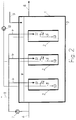
- Fig. 2 eine gegenüber Fig. 1 erweiterte Anlage.
- Fig. 1 shows schematically an arrangement for performing the method.
- Fig. 2 an expanded compared to Fig. 1.
In einem Reaktionsbehälter 1 ist ein Leitrohr 2 mit vertikaler Achse angeordnet. Das Leitrohr 2 ist an beiden Enden offen. Sein unteres Ende hat einen ausreichenden Abstand vom Boden 3 des Reaktionsbehälters 1, so daß die in demselben vorhandene Flüssigkeit in einem durch das Leitrohr 2 führenden Kreislauf bewegt werden kann. Die Flüssigkeit ist ein Biomasse-Wasser-Gemisch.A
Das zu reinigende Abwasser wird dem Leitrohr 2 über eine Rohrleitung 4 zugeführt. Es tritt an der Stelle S1 in das Leitrohr 2 ein. Über mindestens eine Rohrleitung 5 wird außerdem Gas in das Leitrohr 2 eingeführt, das an den Stellen S2 und S3 austritt. Die Stellen S1 sowie S2 und S3 sind räumlich voneinander getrennt. Die Stellen S2 und S3 liegen dabei in der durch den Pfeil P gekennzeichneten Strömungsrichtung des Abwassers im Leitrohr 2 hinter der Stelle S1. Abweichend von der zeichnerischen Darstellung könnte das Gas auch über zwei getrennte Zuleitungen zu den Stellen S2 und S3 gebracht werden.The wastewater to be cleaned is fed to the
Das Verfahren nach der Erfindung arbeitet beispielsweise wie folgt:The method according to the invention works, for example, as follows:
Das zu reinigende, aus einer Leitung 6 kommende Abwasser (Rohabwasser) wird über die Rohrleitung 4 zusammen mit aus dem Reaktionsbehälter 1 entnommener Flüssigkeit dem Leitrohr 2 des Reaktionsbehälters 1 zugeführt. Bei hinreichender Geschwindigkeit dieser Flüssigkeit, die über eine Pumpe 7 eingestellt werden kann, stellt sich eine Schlaufenströmung um das Leitrohr 2 ein. Das gereinigte Abwasser verläßt den Reaktionsbehälter 1 gemeinsam mit Biomasse über eine Leitung 8. In einer nachgeschalteten, hier nicht gezeigten Vorrichtung werden Abwasser und Biomasse voneinander getrennt. Die Biomasse wird zum größten Teil über eine Leitung 9 in den Reaktionsbehälter 1 zurückgeführt. Der Rest der Biomasse wird als Überschußschlamm entnommen.The wastewater (raw wastewater) to be cleaned, coming from a
Der für die Abwasserreinigung erforderliche Sauerstoff wird als Gas, in der Regel Luft oder auch angereichertes oder reines Sauerstoffgas, über die Rohrleitung 5 in das Leitrohr 2 des Reaktionsbehälters 1 eingebracht. Die Rohrleitung 5 kann, wie in Fig. 1 dargestellt, von oben, aber auch seitlich in das Leitrohr 2 eingeführt werden. Die Mündung der Rohrleitung 5 befindet sich im unteren Bereich des Leitrohrs 2, zweckmäßigerweise im unteren Fünftel desselben. Je nach Höhe der Zweiphasenschicht im Reaktionsbehälter 1 wird das Gas mittels einer Pumpe 10 mehr oder weniger verdichtet. Die Dispergierung des Gases erfolgt an der Stelle S2 durch Scherwirkung des an der Stelle S1 austretenden Abwassers und an der Stelle S3 durch die 180 Grad-Umlenkung der Flüssigkeit am unteren Ende des Leitrohrs 2. Bei entsprechender Geschwindigkeit der aus der Rohrleitung 4 austretenden Flüssigkeit wird der überwiegende Teil des im das Leitrohr 2 umgebenden Mantelraum des Reaktionsbehälters 1 aufsteigenden Gases in das Leitrohr 2 zurückgesaugt, wodurch eine Rezirkulation des Gases erreicht wird. Eine dem insgesamt zugeführten Gas entsprechende Gasmenge verläßt den Reaktionsbehälter 1 über eine Leitung 11.The oxygen required for wastewater treatment is introduced as gas, usually air or also enriched or pure oxygen gas, via the
Da das Verhältnis von Höhe zu Durchmesser des Reaktionsbehälters 1 und des Leitrohrs 2 und die Geschwindigkeit der Flüssigkeit in demselben aus fluiddynamischen Gründen bestimmte Werte einhalten müssen und weil die Bauhöhe von Reaktionsbehälter 1 und Leitrohr 2 aus energetischen Gründen beschränkt ist, werden bei großen Abwassermengen zweckmäßig zwei oder mehr Leitrohre 2 mit entsprechenden Zuleitungen in einem Reaktionsbehälter 1 angeordnet. Das ist in Fig. 2 für drei Leitrohre 2 dargestellt. Der Einbau von mehreren Leitrohren 2 in einen Reaktionsbehälter 1 hat den zusätzlichen Vorteil, daß die Dispergierung des in den jeweiligen Leitrohren 2 an den Stellen S2 und S3 zugeführten Gases durch einen Pralleffekt der umgelenkten und aufeinander prallenden Flüssigkeitsströme noch verstärkt wird.Since the ratio of the height to the diameter of the
Claims (6)
Applications Claiming Priority (4)
| Application Number | Priority Date | Filing Date | Title |
|---|---|---|---|
| DE19539758 | 1995-10-26 | ||
| DE19539758 | 1995-10-26 | ||
| DE1996135443 DE19635443A1 (en) | 1995-10-26 | 1996-08-31 | Process for the biological treatment of waste water |
| DE19635443 | 1996-08-31 |
Publications (1)
| Publication Number | Publication Date |
|---|---|
| EP0770580A1 true EP0770580A1 (en) | 1997-05-02 |
Family
ID=26019776
Family Applications (1)
| Application Number | Title | Priority Date | Filing Date |
|---|---|---|---|
| EP19960116837 Withdrawn EP0770580A1 (en) | 1995-10-26 | 1996-10-19 | Process for the biological purification of waste water |
Country Status (7)
| Country | Link |
|---|---|
| US (1) | US5837141A (en) |
| EP (1) | EP0770580A1 (en) |
| JP (1) | JPH09174075A (en) |
| CN (1) | CN1079379C (en) |
| CA (1) | CA2188706A1 (en) |
| NO (1) | NO964556L (en) |
| PL (1) | PL316520A1 (en) |
Cited By (1)
| Publication number | Priority date | Publication date | Assignee | Title |
|---|---|---|---|---|
| WO2017037168A1 (en) * | 2015-09-04 | 2017-03-09 | Thyssenkrupp Industrial Solutions Ag | Apparatus for biological liquid purification with a loop reactor |
Families Citing this family (2)
| Publication number | Priority date | Publication date | Assignee | Title |
|---|---|---|---|---|
| US6153099A (en) * | 1998-12-21 | 2000-11-28 | Smith & Loveless, Inc. | Biological waste treatment process and apparatus |
| EP1409419A4 (en) * | 2001-05-31 | 2009-06-24 | Biothane Corp | Anaerobic digestion apparatus, methods for anaerobic digestion a nd for minimizing the use of inhibitory polymers in digestion |
Citations (5)
| Publication number | Priority date | Publication date | Assignee | Title |
|---|---|---|---|---|
| US4278546A (en) * | 1975-10-22 | 1981-07-14 | Imperial Chemical Industries Limited | Treatment of a liquid by circulation and gas contacting |
| DE3413537A1 (en) * | 1983-06-30 | 1985-10-24 | Martin Dipl.-Ing. 6349 Breitscheid Menges | Reactor for the biological purification of waste water |
| EP0164508A1 (en) * | 1984-05-16 | 1985-12-18 | Nippon Sangyo Kikai Kabushiki Kaisha | Sewage treatment apparatus |
| US4954257A (en) * | 1987-09-03 | 1990-09-04 | Tecon Gmbh | Biological purification loop device and method having deflector plate within guide pipe |
| EP0475540A1 (en) * | 1990-08-24 | 1992-03-18 | Preussag Noell Wassertechnik GmbH | Process and apparatus for removing ammonium, nitrite and/or nitrate from water |
Family Cites Families (6)
| Publication number | Priority date | Publication date | Assignee | Title |
|---|---|---|---|---|
| CH529073A (en) * | 1971-09-02 | 1972-10-15 | Kaelin J R | Process for the introduction and circulation of oxygen or oxygen-containing gas in a liquid to be clarified and equipment for carrying out the process |
| DE2805793A1 (en) * | 1978-02-11 | 1979-08-16 | Hoechst Ag | METHOD FOR BIOLOGICAL PURIFICATION OF WASTE WATER |
| EP0037659B1 (en) * | 1980-04-03 | 1984-08-01 | Imperial Chemical Industries Plc | Method and apparatus for the treatment of wastewater |
| DE3323514A1 (en) * | 1983-06-30 | 1985-01-10 | Menges, Martin, Dipl.-Ing., 6349 Breitscheid | COMPACT REACTOR FOR THE BIOLOGICAL INTENSIVE TREATMENT OF WASTEWATER, WITH THE SIMULTANEOUS BINDING OF THE VACUUM C-CONNECTIONS (POC) |
| US5364530A (en) * | 1988-11-17 | 1994-11-15 | Otto Oeko-Tech Gmbh & Co. Kg | Process for the biological purification of sewage |
| DE4012300A1 (en) * | 1990-04-18 | 1991-10-24 | Palo Umwelttechnologien Gmbh & | METHOD FOR BIOLOGICALLY CLEANING WASTEWATER AND SYSTEM FOR CARRYING OUT THE METHOD |
-
1996
- 1996-10-15 PL PL31652096A patent/PL316520A1/en unknown
- 1996-10-19 EP EP19960116837 patent/EP0770580A1/en not_active Withdrawn
- 1996-10-24 US US08/736,552 patent/US5837141A/en not_active Expired - Fee Related
- 1996-10-24 CA CA 2188706 patent/CA2188706A1/en not_active Abandoned
- 1996-10-25 NO NO964556A patent/NO964556L/en unknown
- 1996-10-25 JP JP31845196A patent/JPH09174075A/en active Pending
- 1996-10-26 CN CN96121966A patent/CN1079379C/en not_active Expired - Fee Related
Patent Citations (5)
| Publication number | Priority date | Publication date | Assignee | Title |
|---|---|---|---|---|
| US4278546A (en) * | 1975-10-22 | 1981-07-14 | Imperial Chemical Industries Limited | Treatment of a liquid by circulation and gas contacting |
| DE3413537A1 (en) * | 1983-06-30 | 1985-10-24 | Martin Dipl.-Ing. 6349 Breitscheid Menges | Reactor for the biological purification of waste water |
| EP0164508A1 (en) * | 1984-05-16 | 1985-12-18 | Nippon Sangyo Kikai Kabushiki Kaisha | Sewage treatment apparatus |
| US4954257A (en) * | 1987-09-03 | 1990-09-04 | Tecon Gmbh | Biological purification loop device and method having deflector plate within guide pipe |
| EP0475540A1 (en) * | 1990-08-24 | 1992-03-18 | Preussag Noell Wassertechnik GmbH | Process and apparatus for removing ammonium, nitrite and/or nitrate from water |
Cited By (1)
| Publication number | Priority date | Publication date | Assignee | Title |
|---|---|---|---|---|
| WO2017037168A1 (en) * | 2015-09-04 | 2017-03-09 | Thyssenkrupp Industrial Solutions Ag | Apparatus for biological liquid purification with a loop reactor |
Also Published As
| Publication number | Publication date |
|---|---|
| NO964556L (en) | 1997-04-28 |
| CA2188706A1 (en) | 1997-04-27 |
| CN1079379C (en) | 2002-02-20 |
| JPH09174075A (en) | 1997-07-08 |
| PL316520A1 (en) | 1997-04-28 |
| NO964556D0 (en) | 1996-10-25 |
| CN1153745A (en) | 1997-07-09 |
| US5837141A (en) | 1998-11-17 |
Similar Documents
| Publication | Publication Date | Title |
|---|---|---|
| EP0652039B1 (en) | Washing tower for a flue gas desulphurisation system | |
| CH630046A5 (en) | Method for the continuous entry of air or other oxygen-containing gases into an activated-sludge-containing wastewater or fermentation broths | |
| EP0367756B1 (en) | Process and apparatus for the denitrification of liquids | |
| DE2607963A1 (en) | METHOD AND DEVICE FOR GASIFYING LIQUIDS | |
| EP0453881B1 (en) | Process and apparatus for biological purification of waste water | |
| EP0770580A1 (en) | Process for the biological purification of waste water | |
| DE19635443A1 (en) | Process for the biological treatment of waste water | |
| EP1670723B1 (en) | Method for biologically purifying waste water | |
| DE4217491C1 (en) | Compact sewage treatment plant - comprising container with screen, pumps, aerators and two flotation devices, and second container aerobic reactor surrounded by anaerobic reactor | |
| DE10245466B4 (en) | Process for the biological purification of wastewater | |
| DE3130597C2 (en) | Method and device for gassing a liquid | |
| DD200133A1 (en) | DEVICE FOR ANAEROBIC TREATMENT OF SLEEP AND EQUIPMENT | |
| DE19631796A1 (en) | Biological purification for treating sewage | |
| EP0102435B1 (en) | Process and apparatus for maintaning a fine gas dispersion in liquids | |
| DE19707425A1 (en) | Method and device for introducing oxygen into water or aqueous solutions | |
| DE102005016080B4 (en) | Device for biological cleaning of waste water, has a reaction container containing microorganisms in which the waste water and gas are supplied over two tubes existing out of two component nozzles concentrically arranged with one another | |
| EP0739860A1 (en) | Process and apparatus for the biological treatment of waste water | |
| DE3838846C2 (en) | ||
| EP0118621A1 (en) | Process and apparatus for the anaerobic treatment of sludge or highly polluted waste water | |
| DE4312971A1 (en) | Process and apparatus for aerating waters | |
| DE2542656A1 (en) | PROCEDURE FOR DISPERSING GASES INTO A CONTINGENT LIQUID PHASE | |
| EP0117463B1 (en) | Process and apparatus for the gasification and degasification of liquids | |
| DE19702884C2 (en) | Device for cleaning waste water with ozone | |
| EP0120188A1 (en) | Apparatus for the anaerobic treatment of raw sludge or heavily polluted waste water | |
| DE2502137A1 (en) | Chemical sewage treatment - by converting chemicals to gaseous phase and finely distributing as aerosol bubbles |
Legal Events
| Date | Code | Title | Description |
|---|---|---|---|
| PUAI | Public reference made under article 153(3) epc to a published international application that has entered the european phase |
Free format text: ORIGINAL CODE: 0009012 |
|
| AK | Designated contracting states |
Kind code of ref document: A1 Designated state(s): AT CH DE DK ES FI FR GB GR IT LI NL SE |
|
| 17P | Request for examination filed |
Effective date: 19970429 |
|
| GRAG | Despatch of communication of intention to grant |
Free format text: ORIGINAL CODE: EPIDOS AGRA |
|
| 17Q | First examination report despatched |
Effective date: 19981015 |
|
| GRAG | Despatch of communication of intention to grant |
Free format text: ORIGINAL CODE: EPIDOS AGRA |
|
| GRAH | Despatch of communication of intention to grant a patent |
Free format text: ORIGINAL CODE: EPIDOS IGRA |
|
| STAA | Information on the status of an ep patent application or granted ep patent |
Free format text: STATUS: THE APPLICATION IS DEEMED TO BE WITHDRAWN |
|
| 18D | Application deemed to be withdrawn |
Effective date: 19990601 |