EP2626323B1 - Yarn winding device provided with a yarn accumulating device - Google Patents
Yarn winding device provided with a yarn accumulating device Download PDFInfo
- Publication number
- EP2626323B1 EP2626323B1 EP13150070.4A EP13150070A EP2626323B1 EP 2626323 B1 EP2626323 B1 EP 2626323B1 EP 13150070 A EP13150070 A EP 13150070A EP 2626323 B1 EP2626323 B1 EP 2626323B1
- Authority
- EP
- European Patent Office
- Prior art keywords
- yarn
- section
- winding
- accumulating
- accumulating roller
- Prior art date
- Legal status (The legal status is an assumption and is not a legal conclusion. Google has not performed a legal analysis and makes no representation as to the accuracy of the status listed.)
- Active
Links
Images


Classifications
-
- B—PERFORMING OPERATIONS; TRANSPORTING
- B65—CONVEYING; PACKING; STORING; HANDLING THIN OR FILAMENTARY MATERIAL
- B65H—HANDLING THIN OR FILAMENTARY MATERIAL, e.g. SHEETS, WEBS, CABLES
- B65H51/00—Forwarding filamentary material
- B65H51/20—Devices for temporarily storing filamentary material during forwarding, e.g. for buffer storage
- B65H51/22—Reels or cages, e.g. cylindrical, with storing and forwarding surfaces provided by rollers or bars
-
- B—PERFORMING OPERATIONS; TRANSPORTING
- B65—CONVEYING; PACKING; STORING; HANDLING THIN OR FILAMENTARY MATERIAL
- B65H—HANDLING THIN OR FILAMENTARY MATERIAL, e.g. SHEETS, WEBS, CABLES
- B65H2701/00—Handled material; Storage means
- B65H2701/30—Handled filamentary material
- B65H2701/31—Textiles threads or artificial strands of filaments
Description
- The present invention relates to a yarn winding device provided with a yarn accumulating device.
-
WO 2011/040545 discloses an automatic winder adapted to rewind a yarn unwound from a yarn supplying bobbin while removing a yarn defect such as slub to form a package. The automatic winder ofWO 2011/040545 includes various devices such as a yarn joining device, a yarn accumulating device, and the like between the yarn supplying bobbin and a package winding section adapted to wind the yarn. The yarn joining device joins the yarn from the package and the yarn from the yarn supplying bobbin at the time of replacing the yarn supplying bobbin, after performing yarn cutting operation to remove the yarn defect, and after occurrence of an unexpected yarn breakage. The yarn accumulating device includes a rotating yarn accumulating roller (rotating accumulating drum), and temporarily accumulates the yarn that is not yet wound into a package by winding the yarn around the yarn accumulating roller. - In the above automatic winder, during the winding of the yarn by the package winding section, the yarn accumulating roller of the yarn accumulating device arranged between the yarn supplying bobbin and the package winding section winds the yarn unwound from the yarn supplying bobbin, and unwinds the yarn wound around the yarn accumulating roller towards the package winding section. The yarn accumulating roller rotates with a prescribed amount of yarn wound therearound. The rotation of the yarn accumulating roller is stopped when performing yarn joining operation by the yarn joining device. At the time of the yarn joining operation, although the yarn is not supplied from the yarn supplying bobbin, since a prescribed amount of yarn is accumulated in the yarn accumulating roller, the yarn of the yarn accumulating roller is unwound and wound by the package winding section. In this manner, the winding of the yarn by the package winding section is continuously carried out without being stopped even at the time of the yarn joining operation.
- The yarn accumulating device of
WO 2011/040545 adopts a method of accumulating the yarn by winding the yarn around the rotating yarn accumulating roller. If the winding speed of the package winding section is large, the yarn accumulated in the yarn accumulating device quickly runs out during the yarn joining operation, and hence the yarn accumulating amount of the yarn accumulating device is desirably large. However, the amount of yarn that can be accumulated in the yarn accumulating device is proportional to the size (outer diameter and length) of the yarn accumulating roller. That is, the yarn accumulating roller needs to be large in order to increase the yarn accumulating amount, which consequently increases the inertia moment of the yarn accumulating roller. In this case, it becomes difficult to quickly control the rotation of the roller, for example, the yarn accumulating roller cannot be promptly stopped when starting the yarn joining operation. Alternatively, a large motor can be adopted to rotationally drive the yarn accumulating roller, but this greatly increases the cost and is also disadvantageous in terms of energy consumption. - An object of the present invention is to reduce a weight of the yarn accumulating roller and realize a quick rotational control of the yarn accumulating roller.
- This is achieved by a yarn winding device according to
claim 1. - According to the present invention, since the cylindrical yarn accumulating roller is formed of a resin material, the weight of the yarn accumulating roller can be reduced compared to when being formed of a metal material. Therefore, a prompt rotational control of the yarn accumulating roller can be carried out without enlarging the motor.
- In accordance with a second aspect of the invention, in the yarn accumulating device, the yarn accumulating roller is formed of a fiber reinforced resin in which reinforced fiber is contained in the resin material. According to the present invention, high strength can be ensured in addition to the reduction in weight of the yarn accumulating roller.
- According to the present invention, since the portion around which the yarn is wound of the yarn accumulating roller is covered with the protective layer, deformation, scratches, abrasion, or the like caused by the winding of the yarn are suppressed from occurring at the outer surface of the yarn accumulating roller made of resin material, thus improving durability.
- According to the present invention, the entire surface of the yarn accumulating roller is protected with the plated layer serving as the protective layer. In the case of plating, it is generally easier to form the plated layer on the entire surface rather than forming the plated layer only on one part of the base material.
- In accordance with the second aspect of the invention, in the yarn accumulating device, the yarn accumulating roller is formed of ABS resin.
- The ABS resin (copolymeric synthetic resin of Acrylonitrile, Butadiene, and Styrene) has high moldability and is suited for molding of the yarn accumulating roller. The chromium plating has high corrosion resistance and excels in hardness of the roller surface and the improvement of the abrasion resistance. However, it is difficult to form the chromium plating through electrolytic plating on the surface of the ABS resin, which is an insulating material. However, in the present invention, the chromium plating can be formed with electrolytic plating since the base layer having nickel or copper as the main component that can be formed with non-electrolytic plating or the like exists on the surface of the ABS resin.
- According to the present invention, the yarn accumulating device is arranged between the yarn supplying section and the yarn defect removing device. Thus, even in a state in which the yarn is not supplied from the yarn supplying section to the winding section at the time of removing the yarn defect, the winding section winds the yarn accumulated in the yarn accumulating device, and hence the winding operation of the winding section can be continuously carried out.
- In accordance with a third aspect of the invention, in the yarn winding device, the yarn defect removing device includes a yarn defect detecting device adapted to detect the defect of the travelling yarn, a yarn cutting section adapted to cut the yarn when the yarn defect is detected by the yarn defect detecting device, and a yarn joining device adapted to join a yarn end from the yarn accumulating device and a yarn end from the yarn supplying section while removing the yarn defect after the yarn is cut by the yarn cutting section.
- In the present invention, when the yarn defect is detected by the yarn defect detecting device, the yarn is first cut by the yarn cutting section. Thereafter, the yarn joining device joins the yarn end from the yarn accumulating device and the yarn end from the yarn supplying section. Then, the yarn joining device removes the yarn defect upon joining the yarn ends. During such series of operations, the yarn is not supplied from the yarn supplying section, but the winding section winds the yarn unwound from the yarn accumulating roller of the yarn accumulating device, so that the winding operation can be continued.
- In accordance with an fourth aspect of the invention, the yarn winding device further includes: a control section adapted to control a winding operation of the winding section and a yarn accumulating operation of the yarn accumulating roller of the yarn accumulating device; and a yarn amount detecting section adapted to detect an amount of yarn accumulated in the yarn accumulating device; wherein the control section stops rotation of the yarn accumulating roller and controls the winding operation of the winding section according to a detection result of the yarn amount detecting section when the yarn is cut by the yarn cutting section.
- In the present invention, when a state in which the amount of yarn of the yarn accumulating device is small is detected by the yarn amount detecting section, the winding operation of the winding section is stopped or the winding speed is reduced to prevent the yarn accumulated in the yarn accumulating device from running out.
In the following, the present invention is illustrated with more detail with regard to an embodiment disclosed in the enclosed drawings.
Figure 1 is a side view of a winding unit of an automatic winder according to the present invention;
figure 2 is a side view of a yarn accumulating device according to the invention;
figure 3 is a cross sectional view in a plain including an axis center of the yarn accumulating roller according to the invention;
figure 4 is an enlarged cross-sectional view of an outer peripheral portion of the yarn accumulating roller offigure 3 ; and
figure 5 is a flow chart showing the control of the package winding operation including the yarn joining operation performed by the unit control section according to the invention. - An embodiment of the present invention will be described below. The present embodiment is an example in which the present invention is applied to an automatic winder including a plurality of winding units (yarn winding devices), adapted to wind a yarn unwound from a yarn supplying bobbin to form a winding package. The automatic winder has a configuration in which the plurality of winding units, each forming one package, is arranged in a line in one direction.
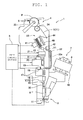
FIG. 1 is a side view of one winding unit of the automatic winder. - As illustrated in
FIG. 1 , eachwinding unit 1 includes abobbin supplying device 2, ayarn supplying section 3, apackage winding section 4, and aunit control section 5 for controlling each section of thewinding unit 1. With theyarn supplying bobbin 8 supplied from thebobbin supplying device 2 being held by theyarn supplying section 3, thewinding unit 1 winds a spun yarn Y unwound from theyarn supplying bobbin 8 around awinding tube 6 while traversing the spun yarn Y by thepackage winding section 4 to form a package P of a predetermined shape. - The
bobbin supplying device 2 includes arotary magazine 10 capable of holding an extra supply ofyarn supplying bobbins 8. When themagazine 10 is intermittently rotated, oneyarn supplying bobbin 8 is dropped diagonally so that theyarn supplying bobbin 8 is supplied to theyarn supplying section 3. - The
yarn supplying section 3 holds theyarn supplying bobbin 8 in a replaceable manner. Specifically, theyarn supplying bobbin 8 supplied from thebobbin supplying device 2 is held in a substantially upright state by a bobbin holding tool (not illustrated) inserted to a lower end of theyarn supplying bobbin 8. When the yarn of theyarn supplying bobbin 8 is all unwound and theyarn supplying bobbin 8 becomes empty, theyarn supplying section 3 can flip up theyarn supplying bobbin 8 by aspringboard 11 to discharge theyarn supplying bobbin 8 outside theyarn supplying section 3. - On a yarn travelling path between the
yarn supplying section 3 and thepackage winding section 4, an unwinding assistingdevice 15, a lower yarn blow-updevice 16, atension applying device 17, an upperyarn catching device 18, ayarn joining device 19, ayarn trap 20, a clearer 21, and ayarn accumulating device 22 are arranged in this order from theyarn supplying section 3. - The unwinding assisting
device 15 lowers atube body 30, which covers an upper end of theyarn supplying bobbin 8, with advancement in the unwinding of the yarn Y to regulate bulging (balloon) of the yarn Y during the unwinding and stabilize the unwinding tension. - The lower yarn blow-up
device 16 is connected to a compressed air source (not illustrated), and is configured to generate an upward airflow at the time of the yarn joining operation to blow up a lower yarn Y2 from theyarn supplying bobbin 8 towards theyarn joining device 19. - The
tension applying device 17 is adapted to apply a predetermined tension on the travelling yarn Y. Thetension device 17 may be, for example, a gate-type which includes fixed comb teeth and movable comb teeth movably arranged with respect to the fixed comb teeth. - The upper
yarn catching device 18 is connected to a negative pressure source (not illustrated), and is adapted to generate a suction airflow during the yarn joining operation to suck and catch an upper yarn Y1 from theyarn accumulating device 22 guided by aguide member 32, to be described later. - The
yarn trap 20 is connected to the negative pressure source (not illustrated), and catches the lower yarn Y2 blown up by the lower yarn blow-updevice 16 at the time of the yarn joining operation. - The
yarn joining device 19 joins the lower yarn Y2 from theyarn supplying bobbin 8 and the upper yarn Y1 from the winding side (yarn accumulating device 22) at the time of replacing theyarn supplying bobbin 8, after yarn cut carried out when the clearer 21, described later, detects a yarn defect, or after yarn breakage during the unwinding of the yarn from theyarn supplying bobbin 8. Theyarn joining device 19 may be the yarn joining device 19 (air splicer) including an untwisting nozzle adapted to untwist the yarn end of the upper yarn Y1 and the yarn end of the lower yarn Y2, and a twisting nozzle adapted to apply a whirling airflow on the untwisted yarn ends to twist the yarn ends together. - The clearer 21 (yarn defect detecting device) is arranged on the yarn travelling path between the
yarn supplying section 3 and theyarn accumulating device 22, and detects a yarn defect such as slub of the yarn Y travelling through the yarn travelling path. The clearer 21 is provided with a cutter 31 (yarn cutting section) adapted to cut the yarn when the clearer 21 detects the yarn defect. - The substantially
tubular guide member 32 is arranged on the side of theyarn joining device 19 between the upperyarn catching device 18 and theyarn accumulating device 22 so as to circumvent a linear yarn travelling path during the normal winding. Furthermore, aslit 32a is formed over the entire length of theguide member 32 in a side wall (left side in the figure) of theguide member 32. - At the time of the yarn joining operation, the upper yarn Y1 from the
yarn accumulating device 22 is pulled out by an upper yarn pull-outdevice 42 of theyarn accumulating device 22, to be described later, and fed to theguide member 32, and the yarn end of the upper yarn Y1 is passed through theguide member 32 to be caught by the upperyarn catching device 18. Furthermore, when the yarn is pulled by the upperyarn catching device 18, the yarn is pulled out to the outside of theguide member 32 from theslit 32a and guided to theyarn joining device 19. The lower yarn Y2 from theyarn supplying bobbin 8 is blown upward by the lower yarn blow-updevice 16. Moreover, the blown-up yarn is caught and pulled by theyarn trap 20 to be guided to theyarn joining device 19. After the upper yarn Y1 and the lower yarn Y2 are set in theyarn joining device 19 in this manner, theyarn joining device 19 joins the upper yarn Y1 and the lower yarn Y2. - Although not illustrated, the
yarn joining device 19 includes a cutter adapted to cut the ends of the guided upper yarn Y1 and the lower yarn Y2. The yarn defect in the upper yarn Y1 is removed at the time of the cutting operation performed by the cutter in the yarn joining operation when the yarn defect is detected. After the cutting operation, the yarn ends of the upper yarn Y1 and the lower yarn Y2 are joined. - In the present embodiment, a device group such as the lower yarn blow-up
device 16, the upperyarn catching device 18, theyarn joining device 19, theyarn trap 20, the clearer 21, and thecutter 31 corresponds to a "yarn defect removing device" in the invention of the present application, which detects and removes the yarn defect from the travelling yarn Y. - The
yarn accumulating device 22 is arranged between theyarn joining device 19 and thepackage winding section 4. Theyarn accumulating device 22 temporarily accumulates the yarn Y that is not yet wound by thepackage winding section 4. The details on the structure of theyarn accumulating device 22 will be described later. - The package winding section 4 (winding section) includes a
cradle 33 which has a pair of cradle arms for rotatably and detachably supporting the windingtube 6, and atraverse drum 34 which can make contact with the surface of the windingtube 6 supported by thecradle 33 or the surface of a package P formed on the windingtube 6. Thepackage winding section 4 is configured such that, by rotating thetraverse drum 34 by a drum driving motor (not illustrated) with thetraverse drum 34 making contact with the winding tube 6 (or the surface of the package P), the windingtube 6 is rotated (accompanying rotation) accompanying the rotation of thetraverse drum 34 while traversing the yarn unwound from theyarn accumulating device 22, to thereby form the package P on the outer periphery of the windingtube 6. - In the present embodiment, since the
yarn accumulating device 22 adapted to accumulate the yarn Y is arranged between theyarn supplying section 3 and thepackage winding section 4, thepackage winding section 4 can wind the yarn accumulated in theyarn accumulating device 22 and the winding of the package P can be continued even if the unwinding of the yarn from theyarn supplying bobbin 8 is interrupted for some reason (e.g., during the yarn joining operation by the yarn joining device 19). - The unit control section 5 (control section) is configured by a CPU (Central Processing Unit) which is an arithmetic processing unit, a ROM (Read-Only Memory) which stores programs executed by the CPU and data used in the program, a RAM (Random Access Memory) which temporarily stores the data during the execution of the program, and an input/output interface for inputting and outputting data from and to outside. The
unit control section 5 controls the operation of each device of the above-described windingunit 1 based on a command sent from a machine control device (not illustrated), which performs the overall control of the automatic winder. - Next, the
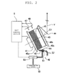
yarn accumulating device 22 will be described in detail.FIG. 2 is a side view of theyarn accumulating device 22. As illustrated inFIG. 1 andFIG. 2 , theyarn accumulating device 22 includes a cylindricalyarn accumulating roller 40 around which the yarn is wound by rotating, aroller driving motor 41 which rotatably drives theyarn accumulating roller 40, and an upper yarn pull-outdevice 42 which pulls out the yarn end of the yarn wound around theyarn accumulating roller 40 at the time of the yarn joining operation. - As will be specifically described later, the
yarn accumulating roller 40 is formed of a resin material R. As illustrated inFIG. 2 , theyarn accumulating roller 40 is rotatably supported on the machine of the windingunit 1 with an axis C1 which is slightly tilted with respect to a horizontal direction, as a center.Tapered portions yarn accumulating roller 40, respectively. The portion between the twotapered portions cylindrical portion 40c having a constant diameter, and the yarn Y is wound around thecylindrical portion 40c. The yarn Y wound around thecylindrical portion 40c is prevented from falling off by the twotapered portions -
FIG. 3 is a cross-sectional view in a plane including an axis center of theyarn accumulating roller 40. Awall portion 40d is formed inside the cylindricalyarn accumulating roller 40, and ametal coupling member 48 is attached to thewall portion 40d. Arotation shaft 41a of theroller driving motor 41 is coupled to thecoupling member 48. Theroller driving motor 41 is a position controllable motor such as a DC brushless motor, a stepping motor, a servo motor, and the like, and can rotatably drive theyarn accumulating roller 40 in both directions. Since theyarn accumulating roller 40 formed of the resin material R and therotation shaft 41a of theroller driving motor 41 are coupled by themetal coupling member 48 having high strength, the portion coupled with theroller driving motor 41 is less likely to break when the torque of theroller driving motor 41 is applied. - A
guide tube 43 which constitutes one part of the upper yarn pull-outdevice 42, to be described later, is arranged in proximity to the taperedportion 40a on the basal end side of theyarn accumulating roller 40. One end of theguide tube 43 is arranged close to the surface of theyarn accumulating roller 40. At the time of the normal winding, the yarn from theyarn supplying bobbin 8 is guided to the taperedportion 40a on the basal end side of theyarn accumulating roller 40 through theguide tube 43. - When the
yarn accumulating roller 40 is rotated in one direction, the yarn Y guided to the taperedportion 40a on the basal end side of theyarn accumulating roller 40 by theguide tube 43 is sequentially wound while pushing up the previous yarn layer from the basal end side (left side in the figure) of thecylindrical portion 40c. As a result, the yarn that is already wound around theyarn accumulating roller 40 is pushed by the newly wound yarn, and is sequentially fed towards the distal end side. The yarn Y is thus spirally aligned and orderly wound from the basal end side on the outer peripheral surface of thecylindrical portion 40c of theyarn accumulating roller 40. - Meanwhile, the yarn Y wound around the
yarn accumulating roller 40 is pulled out from the taperedportion 40b on the distal end side (right side in the figure) of theyarn accumulating roller 40, and is fed downstream (towards the package winding section 4). At the taperedportion 40b on the distal end side, the yarn on theyarn accumulating roller 40 is pulled out towards the downstream through a pull-out guide 44, which is positioned on an extended line of the center axis C1 of theyarn accumulating roller 40. - A rubber
annular member 45 such as a rubber band, an o ring, or the like is attached to the distal end of thecylindrical portion 40c of the yarn accumulating roller 40 (boundary portion with the distal end side taperedportion 40b). The yarn wound around theyarn accumulating roller 40 is passed between theyarn accumulating roller 40 and theannular member 45 to be unwound, whereby an appropriate tension is applied on the unwinding yarn. Theannular member 45 is prevented from falling off from theyarn accumulating roller 40 by the taperedportion 40b on the distal end side of theyarn accumulating roller 40. - As described above, in the present embodiment, the
yarn accumulating roller 40 is formed of the resin material R which is a non-metal material. As the resin material R for forming theyarn accumulating roller 40, if it is a thermoplastic resin, ABS resin (specific weight: 1.0) (copolymeric synthetic resin of Acrylonitrile (specific weight: 0.6), Butadiene (specific weight: 1.0), and Styrene (specific weight 1.0)) or a polycarbonate (specific weight: 1.2), which excels in moldability may be suitably used. If it is a thermosetting resin, phenol resin (specific weight: 1.25 to 1.5), unsaturated polyester resin (specific weight: 1.1 to 1.46), epoxy resin (specific weight: 1.1 to 1.2), and the like may be suitably used. Including the above examples, the resin material R has a significantly low specific weight compared to the iron-based metal material such as stainless steel (specific weight: 7.7), and thus the weight of theyarn accumulating roller 40 can be greatly reduced compared to the case where theyarn accumulating roller 40 is formed of a metal material. - Furthermore, the
yarn accumulating roller 40 may be formed of a fiber reinforced resin (FRP) in which reinforced fiber is contained in the thermosetting resin. For example, a glass fiber reinforced resin (GFRP) in which glass fiber is contained in the above-described phenol resin and the like, a carbon fiber reinforced resin (CFRP) which contains carbon fiber, and the like may be used. By forming theyarn accumulating roller 40 from a fiber reinforced resin, high strength can be ensured in addition to further reduction in weight of theyarn accumulating roller 40. Moreover, a vibration damping effect can be obtained by the reinforced fiber. - The
yarn accumulating roller 40 can be molded through a general molding method using a die. With the thermoplastic resin, theyarn accumulating roller 40 can be easily molded by injection molding. With the thermosetting resin, theyarn accumulating roller 40 can be molded by transfer molding, compression molding, or injection molding. If the thermosetting resin such as the phenol resin is used, the shrink produced at the time of molding by the die is reduced. Since the phenol resin has a low thermal contraction rate, the accuracy of the surface of the die becomes the accuracy of the resin surface as is, and thus theyarn accumulating roller 40 having a very small surface roughness can be molded. - In the present embodiment, as illustrated in
FIG. 3 , themetal coupling member 48 for coupling theyarn accumulating roller 40 with theroller driving motor 41 is attached to theyarn accumulating roller 40. In such a case, theyarn accumulating roller 40 is preferably molded by insert molding. That is, themetal coupling member 48 is attached in advance to the interior of the die for molding theyarn accumulating roller 40, and the resin material R is then injected into the die to integrally form theyarn accumulating roller 40 and thecoupling member 48. In this case, the positional accuracy of thecoupling member 48 and theyarn accumulating roller 40 to be molded with the die becomes higher by setting the die with thecoupling member 48 as a reference. - Since the resin material R generally has low hardness compared to the metal material, scratches and deformation may occur on the outer surface of the
yarn accumulating roller 40 formed of the resin material R depending on the wound yarn Y. Furthermore, abrasion may occur when the wound yarn Y is rubbed against the outer surface of theyarn accumulating roller 40. Thus, the outer surface of theyarn accumulating roller 40 may be covered with a protective layer H. Accordingly, the deformation, scratches, abrasion, or the like caused by the winding of the yarn are suppressed from occurring on the outer surface of theyarn accumulating roller 40 formed of the resin material R, whereby the durability is improved. - The material of the protective layer H is not particularly limited, but the material excelling in corrosion resistance and abrasion resistance is preferably used. Examples of the material include hard chrome plating, DLC (Diamond-like Carbon), and the like. The covering method may include plating (wet plating), deposition (PVD, CVD, or the like), painting, thermal spraying, and the like. A thin metal film manufactured in a different step may be laminated to the surface of the
yarn accumulating roller 40. - From the viewpoint of preventing scratches and the like caused by the wound yarn Y, the protective layer H is preferably arranged at least on the
tapered portions cylindrical portion 40c, on which the yarn Y is wound, of the outer surface of theyarn accumulating roller 40. However, from the viewpoint of protecting the entireyarn accumulating roller 40, the outer surface of theyarn accumulating roller 40 may be entirely covered with the protective layer H. In particular, in the case of plating, the protective layer H can be easily formed over the entire surface of theyarn accumulating roller 40. Furthermore, in the case of plating, it is generally easier to form the plated layer entirely rather than forming the plated layer only on one part of the base material. - A case of forming the protective layer H by plating will be described by way of example.
FIG. 4 is an enlarged cross-sectional view of an outer peripheral portion of theyarn accumulating roller 40 ofFIG. 3 . First, the outer surface of theyarn accumulating roller 40 formed of the resin material R is etched to form irregularities on the outer surface, and then a catalyst having high reducing ability such as Pd and Sn is added. Then, theyarn accumulating roller 40 added with the catalyst is immersed in a chemical plating solution to carry out non-electrolytic plating, thereby forming a base layer 61, which has nickel or copper as the main component, on the outer surface of theyarn accumulating roller 40. The electrolytic plating thus can be carried out by forming the base layer 61 having conductivity on the outer surface of theyarn accumulating roller 40. Then, a metal platedlayer 60 having chromium as the main component is formed as the protective layer H on the base layer 61 by the electrolytic plating. In the above configuration, the term "main component" refers to a component having the highest weight ratio among the components of each layer. - It should be noted that, regardless of the presence or absence of coating by the protective layer H described above, the physical processing such as blast processing, buffing, and the like may be performed on the outer surface of the
yarn accumulating roller 40, as necessary. - Returning to
FIG. 2 , anupper limit sensor 46 for detecting that the amount of yarn Y on theyarn accumulating roller 40 is greater than or equal to a predetermined upper limit amount, and alower limit sensor 47 for detecting that the amount of yarn Y is smaller than a predetermined lower limit amount are arranged in proximity of the outer peripheral surface of thecylindrical portion 40c of theyarn accumulating roller 40. The detection results of theupper limit sensor 46 and thelower limit sensor 47 are sent to theunit control section 5. Based on the detection results of thesensors unit control section 5 controls theroller driving motor 41 such that the yarn accumulating amount (winding amount) of theyarn accumulating roller 40 is within a range between the upper limit amount and the lower limit amount. Each of theupper limit sensor 46 and thelower limit sensor 47 corresponds to a "yarn amount detecting section" in the invention of the present application. - The upper yarn pull-out
device 42 is a device for pulling out the yarn end of the yarn from the yarn accumulating device 22 (upper yarn Y1) to perform the yarn joining operation by theyarn joining device 19 at the time of replacement of theyarn supplying bobbin 8, after the cutting of the yarn, or after the yarn breakage when the yarn defect is detected. The upper yarn pull-outdevice 42 includes theguide tube 43 mentioned above. Ayarn passage 50 and anozzle 51 connected to theyarn passage 50 are formed inside theguide tube 43. One end of theguide tube 43 faces the taperedportion 40a on the basal end side of theyarn accumulating roller 40, and the above-describedguide member 32 is arranged at the other end of theguide tube 43 with its opening at the upper end facing theguide tube 43. Thenozzle 51 is connected to acompressed air source 52, and anelectromagnetic valve 53 that opens and closes by the signal from theunit control section 5 is arranged between thenozzle 51 and thecompressed air source 52. - At the time of the normal winding, the yarn Y unwound from the
yarn supplying bobbin 8 is passed through theyarn passage 50 of theguide tube 43 and guided to the surface of theyarn accumulating roller 40. At the time of the yarn joining operation, theelectromagnetic valve 53 is switched from close to open, and the compressed air is supplied from thenozzle 51 into theyarn passage 50, so that the airflow directed from theyarn accumulating roller 40 towards theguide member 32 is generated in theyarn passage 50. Under this state, when theyarn accumulating roller 40 is rotated in a direction opposite to the rotation at the time of normal winding, the yarn Y on theyarn accumulating roller 40 is unwound from the basal end side, and the yarn end thereof is pulled into theguide tube 43 by the airflow and further fed from theguide tube 43 to theguide member 32. The yarn end of the upper yarn Y1 fed to theguide member 32 in this manner is guided to and caught by the above-described upperyarn catching device 18, whereby the upper yarn Y1 is fed to theyarn joining device 19. - Next, the control of the package winding operation including the yarn joining operation performed by the
unit control section 5 will be described with reference to a flowchart ofFIG. 5 . In the following, in particular, a series of operations performed when a yarn defect is detected during the package winding will be described. - When a yarn defect of the travelling yarn Y is detected (S10) by the clearer 21 while the package P is being wound, the yarn Y is cut with the cutter 31 (S11). The rotation of the
yarn accumulating roller 40 is stopped (S12). However, thetraverse drum 34 of the package winding section is not stopped. In other words, thepackage winding section 4 unwinds and winds the yarn Y wound around theyarn accumulating roller 40. - Then, the
yarn joining device 19 performs the yarn joining operation (S13). With respect to the lower yarn Y2 from theyarn supplying bobbin 8, the yarn end blown up by the lower yarn blow-updevice 16 illustrated inFIG. 1 is caught by theyarn trap 20 so that the lower yarn Y2 is guided to theyarn joining device 19. The upper yarn Y1 is pulled out by the upper yarn pull-outdevice 42 illustrated inFIG. 1 andFIG. 2 , and the upper yarn Y1 fed to theguide member 32 is caught by the upperyarn catching device 18 so that the upper yarn Y1 is guided to theyarn joining device 19. Theyarn joining device 19 joins the guided lower yarn Y2 and the upper yarn Y1. Then, theyarn joining device 19 removes the yarn defect contained in the upper yarn Y1 upon joining the lower yarn Y2 and the upper yarn Y1. - Since the yarn Y wound around the
yarn accumulating roller 40 is unwound during the yarn joining operation, the amount of yarn accumulated in theyarn accumulating roller 40 is reduced. When the lower limit sensor 47 (seeFIG. 2 ) of theyarn accumulating device 22 detects that the amount of yarn accumulated in theyarn accumulating roller 40 is less than a predetermined lower limit value (S14: Yes) before the yarn joining operation is finished, the winding speed of the package winding section 4 (rotation speed of the traverse drum 34) is reduced to prevent the yarn Y of theyarn accumulating roller 40 from running out (S15). Alternatively, the winding operation of thepackage winding section 4 may be temporarily stopped. - After the yarn joining operation by the
yarn joining device 19 is finished (S16: Yes), theyarn accumulating roller 40 is re-accelerated to resume the unwinding of the yarn Y from the yarn supplying bobbin 8 (S17). If the winding speed of thepackage winding section 4 is reduced or the winding is stopped previously, the winding speed is increased to a predetermined speed. - The
yarn accumulating device 22 is arranged between theyarn supplying section 3 and thepackage winding section 4. Thus, even in a state in which the yarn Y is not supplied from theyarn supplying section 3 to thepackage winding section 4 at the time of removing the yarn defect, thepackage winding section 4 winds the yarn accumulated in theyarn accumulating device 22 to continuously perform the winding operation of thepackage winding section 4. When a state in which the amount of yarn of theyarn accumulating device 22 is small is detected by thelower limit sensor 47, the winding operation of thepackage winding section 4 may be stopped or the winding speed may be reduced to prevent the yarn Y accumulated in theyarn accumulating device 22 from running out. - In the present embodiment described above, the
yarn accumulating roller 40 of theyarn accumulating device 22 is formed of a non-metal material, and theyarn accumulating roller 40 has light weight. In particular, further reduction in weight of theyarn accumulating roller 40 can be realized by forming theyarn accumulating roller 40 with the resin material R. Therefore, the quick rotational control of theyarn accumulating roller 40 can be achieved without enlarging theroller driving motor 41. - Specifically, at the time of the yarn joining operation by the
yarn joining device 19, theyarn accumulating roller 40 can be promptly stopped. Furthermore, after the yarn joining operation is finished, theyarn accumulating roller 40 can be promptly re-accelerated. In the case where the amount of yarn accumulated in theyarn accumulating roller 40 is required to be increased or decreased during the package winding, the rotation speed of theyarn accumulating roller 40 is to be changed. Such changing of the rotation speed can also be promptly performed. - In the above embodiment, an example in which the
yarn accumulating roller 40 is formed of the resin material R has been described, but theyarn accumulating roller 40 may be formed of other non-metal materials. For example, theyarn accumulating roller 40 may be formed of ceramics. Ceramics also has a smaller specific weight compared to that of the metal material, and thus the weight of theyarn accumulating roller 40 can be reduced. If theyarn accumulating roller 40 is formed of ceramics, the hardness of the outer surface of theyarn accumulating roller 40 becomes high. Thus, the durability becomes sufficiently high even if the protective layer H is not provided. However, since the ceramics has low toughness, the protective layer H formed of rubber or resin may be formed on the surface of theyarn accumulating roller 40 made of ceramics for the purpose of preventing cracks. - In addition, the carbon fiber reinforced carbon composite material (CC material) may be used. Generally, the CC material is produced by alternately repeating a step of covering a core material of the carbon fiber with carbon resin such as phenol resin, and a step of firing the same in vacuum at a temperature from 1000°C to 2000°C to carbonize the resin. The specific weight of the general CC material is 1.3 to 1.7.
- The above embodiment is an example in which the present invention is applied to the automatic winder for rewinding the yarn of the yarn supplying bobbin while removing the yarn defect to form a package, but the target of application of the present invention is not limited to the automatic winder. In other words, the present invention can be applied to the yarn winding device other than the automatic winder as long as it is useful to install the yarn accumulating device adapted to accumulate the yarn in the middle of the yarn path from the yarn supplying section to the winding section. For example, in a spinning device adapted to spin and wind the yarn, the present invention can be applied to an accumulating roller adapted to temporarily wind and accumulate the yarn between the spinning section and the winding section.
Claims (4)
- A yarn winding device (1) comprising:a yarn supplying section (3);a winding section (4) adapted to wind a yarn supplied from the yarn supplying section (3) ; wherein a yarn accumulating device (22) which comprises a cylindrical yarn accumulating roller (40) around which the yarn is wound by being rotated is arranged between the yarn supplying section (3) and the winding section (4) and adapted to accumulate the yearn (y) that is not yet wound around the winding section (4); anda yarn defect removing device is arranged between the yarn supplying section (3) and the yarn accumulating device (22), and is adapted to detect and remove a defect of the travelling yarn (y), characterized in that
the yarn accumulating roller (40) is formed of a resin material (R), and
a metal plated layer (60) is applied as a protective layer (H) on the entire outer surface of the yarn accumulating roller (40) and the plated layer (60) is a layer having chromium as a main component, anda base layer (61) having nickel or copper as a main component is formed between the yarn accumulating roller (40) and the plated layer (60). - The yarn winding device (1) according to claim 1, characterized in that the resin material (R) is a fiber reinforced ABS-resin, in which a fiber reinforcement is contained in the A:BS-resin material (R).
- The yarn winding device (1) according to claim 1 or 2, characterized in that
the yarn defect removing device includes
a yarn defect detecting device (21) adapted to detect the defect of the travelling yarn (y),
a yarn cutting section (31) adapted to cut the yarn (y) when the yarn defect is detected by the yarn defect detecting device (21), and
a yarn joining device (19) adapted to join a yarn end (y1) from the yarn accumulating device (22) and a yarn end (y2) from the yarn supplying section (3) while removing the yarn defect after the yarn (y) is cut by the yarn cutting section (31). - The yarn winding device (1) according to claim 3, characterized by further comprising:a control section (5) adapted to control a winding operation of the winding section (4) and a yarn accumulating operation of the yarn accumulating roller (40) of the yarn accumulating device (22); anda yarn amount detecting section (46, 47) adapted to detect an amount of yarn (y) accumulated in the yarn accumulating device (22), whereinthe control section (5) stops rotation of the yarn accumulating roller (40) and controls the winding operation of the winding section (4) according to a detection result of the yarn amount detecting section (46, 47) when the yarn (y) is cut by the yarn cutting section (31).
Applications Claiming Priority (1)
| Application Number | Priority Date | Filing Date | Title |
|---|---|---|---|
| JP2012024295A JP5915219B2 (en) | 2012-02-07 | 2012-02-07 | Yarn winding device |
Publications (3)
| Publication Number | Publication Date |
|---|---|
| EP2626323A2 EP2626323A2 (en) | 2013-08-14 |
| EP2626323A3 EP2626323A3 (en) | 2014-04-09 |
| EP2626323B1 true EP2626323B1 (en) | 2015-06-03 |
Family
ID=47603220
Family Applications (1)
| Application Number | Title | Priority Date | Filing Date |
|---|---|---|---|
| EP13150070.4A Active EP2626323B1 (en) | 2012-02-07 | 2013-01-02 | Yarn winding device provided with a yarn accumulating device |
Country Status (3)
| Country | Link |
|---|---|
| EP (1) | EP2626323B1 (en) |
| JP (1) | JP5915219B2 (en) |
| CN (1) | CN103241594B (en) |
Cited By (1)
| Publication number | Priority date | Publication date | Assignee | Title |
|---|---|---|---|---|
| CN108070930A (en) * | 2016-11-14 | 2018-05-25 | 村田机械株式会社 | Spinning unit and spinning machine |
Families Citing this family (9)
| Publication number | Priority date | Publication date | Assignee | Title |
|---|---|---|---|---|
| JP2015193451A (en) | 2014-03-31 | 2015-11-05 | 村田機械株式会社 | Yarn storage roller and yarn winder |
| JP2016016969A (en) * | 2014-07-10 | 2016-02-01 | 村田機械株式会社 | Yarn storage device, yarn take-up unit, and yarn take-up machine |
| JP2016050054A (en) * | 2014-08-28 | 2016-04-11 | 村田機械株式会社 | Yarn winding device and textile machine |
| JP2016050059A (en) * | 2014-08-29 | 2016-04-11 | 村田機械株式会社 | Yarn winding device, yarn piecing method, and yarn piecing unit |
| JP2016137959A (en) * | 2015-01-27 | 2016-08-04 | 村田機械株式会社 | Yarn winder |
| EP3378979A1 (en) * | 2017-03-22 | 2018-09-26 | Murata Machinery, Ltd. | Spinning machine |
| DE102017110358A1 (en) * | 2017-05-12 | 2018-11-15 | Maschinenfabrik Rieter Ag | Thread contacting component of a cheese producing textile machine |
| BE1025486B1 (en) * | 2017-12-20 | 2019-03-15 | Gilbos N.V. | Buffer method and system for alternating twisted yarns |
| JP2019137944A (en) * | 2018-02-13 | 2019-08-22 | 村田機械株式会社 | Air spinning machine |
Citations (3)
| Publication number | Priority date | Publication date | Assignee | Title |
|---|---|---|---|---|
| DE4127796A1 (en) | 1991-08-22 | 1993-02-25 | Iro Ab | THREAD FOURNISSEUR |
| DE19538135A1 (en) | 1995-10-13 | 1997-04-17 | Terrot Strickmaschinen Gmbh | Thread device for textile machines |
| WO2011040545A1 (en) | 2009-09-30 | 2011-04-07 | 村田機械株式会社 | Yarn winder |
Family Cites Families (14)
| Publication number | Priority date | Publication date | Assignee | Title |
|---|---|---|---|---|
| FR734866A (en) * | 1932-04-08 | 1932-10-29 | Labrut Freres Sarl | Enamelled ceramic coil |
| DE1922430U (en) * | 1965-05-21 | 1965-08-26 | Plastik Fabrik Elbenia Heine & | CYLINDER SLEEVE FOR SPINNING OR TWISTING. |
| DE1288229C2 (en) * | 1968-06-15 | 1979-04-12 | Memminger Gmbh, 7290 Freudenstadt | THREAD DELIVERY DEVICE ON CIRCULAR KNITTING MACHINES |
| FR2190589A2 (en) * | 1972-06-28 | 1974-02-01 | Ugine Kuhlmann | Thread spool - for high speed textile machines, consisting of cellular thermoplastic material |
| JPS5812184B2 (en) * | 1978-11-22 | 1983-03-07 | 帝人株式会社 | Yarn transfer roller |
| DE3437252C1 (en) * | 1984-10-11 | 1986-01-16 | Gustav 7290 Freudenstadt Memminger | Thread storage and delivery device, in particular for textile machines |
| CH670263A5 (en) * | 1986-05-23 | 1989-05-31 | Sulzer Ag | |
| JPH01150678A (en) * | 1987-12-04 | 1989-06-13 | Toa Nenryo Kogyo Kk | Fragile fiber bundle doubler |
| JPH06154453A (en) * | 1992-11-26 | 1994-06-03 | Barudan Co Ltd | Sewing machine |
| JP2005231823A (en) * | 2004-02-20 | 2005-09-02 | Murata Mach Ltd | Yarn winding machine |
| JP2005272090A (en) * | 2004-03-25 | 2005-10-06 | Opelontex Co Ltd | Yarn feeder and yarn feeding method using this device |
| ITUD20040099A1 (en) * | 2004-05-17 | 2004-08-17 | Ricambi Tessili Ri Te S P A | DEVICE AND PROCEDURE FOR TRAINING |
| JP2007223779A (en) * | 2006-02-27 | 2007-09-06 | Murata Mach Ltd | Thread winding machine |
| DE602008005682D1 (en) * | 2007-09-18 | 2011-05-05 | Heraeus Gmbh W C | Coil wound with a gold alloy wire for use in a bonding process |
-
2012
- 2012-02-07 JP JP2012024295A patent/JP5915219B2/en active Active
-
2013
- 2013-01-02 EP EP13150070.4A patent/EP2626323B1/en active Active
- 2013-01-14 CN CN201310024299.XA patent/CN103241594B/en active Active
Patent Citations (4)
| Publication number | Priority date | Publication date | Assignee | Title |
|---|---|---|---|---|
| DE4127796A1 (en) | 1991-08-22 | 1993-02-25 | Iro Ab | THREAD FOURNISSEUR |
| DE19538135A1 (en) | 1995-10-13 | 1997-04-17 | Terrot Strickmaschinen Gmbh | Thread device for textile machines |
| WO2011040545A1 (en) | 2009-09-30 | 2011-04-07 | 村田機械株式会社 | Yarn winder |
| EP2484620A1 (en) | 2009-09-30 | 2012-08-08 | Murata Machinery, Ltd. | Yarn winder |
Non-Patent Citations (2)
| Title |
|---|
| ANONYMOUS: "Faser-Kunststoff-Verbund", WIKIPEDIA-ARTIKEL, 9 November 2011 (2011-11-09), pages 1 - 9, XP055276374, Retrieved from the Internet <URL:https://de.wikipedia.org/wiki/Faser-Kunststoff-Verbund> |
| ANONYMOUS: "Kunststoffmetallisierung", WIKIPEDIA, 16 November 2011 (2011-11-16), pages 1 - 2, XP055276366, Retrieved from the Internet <URL:https://de.wikipedia.org/wiki/Kunststoffmetallisierung> |
Cited By (2)
| Publication number | Priority date | Publication date | Assignee | Title |
|---|---|---|---|---|
| CN108070930A (en) * | 2016-11-14 | 2018-05-25 | 村田机械株式会社 | Spinning unit and spinning machine |
| CN108070930B (en) * | 2016-11-14 | 2021-08-24 | 村田机械株式会社 | Spinning unit and spinning machine |
Also Published As
| Publication number | Publication date |
|---|---|
| JP2013159467A (en) | 2013-08-19 |
| JP5915219B2 (en) | 2016-05-11 |
| EP2626323A2 (en) | 2013-08-14 |
| EP2626323A3 (en) | 2014-04-09 |
| CN103241594B (en) | 2016-12-07 |
| CN103241594A (en) | 2013-08-14 |
Similar Documents
| Publication | Publication Date | Title |
|---|---|---|
| EP2626323B1 (en) | Yarn winding device provided with a yarn accumulating device | |
| EP2664572B1 (en) | Yarn winding device and yarn winding method | |
| JP5287992B2 (en) | Yarn winding device | |
| US8236127B2 (en) | Method and apparatus for manufacturing continuous fiber-reinforced thermoplastic resin pellet | |
| JP5884280B2 (en) | Yarn winding device and yarn winding method | |
| EP2570377B1 (en) | Traverse guide, winding unit, and winding machine | |
| US20130067880A1 (en) | Spinning Machine and Method for Interrupting Yarn Production on a Spinning Machine | |
| EP2998255B1 (en) | Yarn winding device equipped with yarn storage device | |
| EP2674378B1 (en) | Yarn storage device and yarn winding device | |
| JP5365697B2 (en) | Yarn winding device | |
| JP5375967B2 (en) | Yarn winding device | |
| JP2007284196A (en) | Automatic winder | |
| EP3000756B1 (en) | Yarn winding device and textile machine | |
| EP2987755A1 (en) | Yarn winding device and automatic winder | |
| EP2876071A1 (en) | Bobbin holding device, bobbin setting device, and yarn winding machine | |
| US6425545B1 (en) | Method and apparatus of building multiple packages on a single collet | |
| JP2017065896A (en) | Thread guard member, yarn storage device, and yarn winding machine | |
| JP2014108893A (en) | Production method for package for dyeing formed as cross winding package | |
| JP2015044685A (en) | Yarn end capturing device and yarn winding device | |
| WO2012120963A1 (en) | Thread retaining/drawing-out apparatus, and thread winding apparatus | |
| JP6730071B2 (en) | Filament winding equipment | |
| CN112110281A (en) | Yarn winding device and method for forming a covered yarn | |
| KR20190060471A (en) | Device for continuous supplying filament | |
| JP2010163224A (en) | Yarn winding machine and method of manufacturing package |
Legal Events
| Date | Code | Title | Description |
|---|---|---|---|
| PUAI | Public reference made under article 153(3) epc to a published international application that has entered the european phase |
Free format text: ORIGINAL CODE: 0009012 |
|
| AK | Designated contracting states |
Kind code of ref document: A2 Designated state(s): AL AT BE BG CH CY CZ DE DK EE ES FI FR GB GR HR HU IE IS IT LI LT LU LV MC MK MT NL NO PL PT RO RS SE SI SK SM TR |
|
| AX | Request for extension of the european patent |
Extension state: BA ME |
|
| PUAL | Search report despatched |
Free format text: ORIGINAL CODE: 0009013 |
|
| AK | Designated contracting states |
Kind code of ref document: A3 Designated state(s): AL AT BE BG CH CY CZ DE DK EE ES FI FR GB GR HR HU IE IS IT LI LT LU LV MC MK MT NL NO PL PT RO RS SE SI SK SM TR |
|
| AX | Request for extension of the european patent |
Extension state: BA ME |
|
| RIC1 | Information provided on ipc code assigned before grant |
Ipc: B65H 51/22 20060101AFI20140228BHEP |
|
| 17P | Request for examination filed |
Effective date: 20140710 |
|
| RBV | Designated contracting states (corrected) |
Designated state(s): AL AT BE BG CH CY CZ DE DK EE ES FI FR GB GR HR HU IE IS IT LI LT LU LV MC MK MT NL NO PL PT RO RS SE SI SK SM TR |
|
| GRAP | Despatch of communication of intention to grant a patent |
Free format text: ORIGINAL CODE: EPIDOSNIGR1 |
|
| INTG | Intention to grant announced |
Effective date: 20150106 |
|
| GRAS | Grant fee paid |
Free format text: ORIGINAL CODE: EPIDOSNIGR3 |
|
| GRAA | (expected) grant |
Free format text: ORIGINAL CODE: 0009210 |
|
| STAA | Information on the status of an ep patent application or granted ep patent |
Free format text: STATUS: THE PATENT HAS BEEN GRANTED |
|
| AK | Designated contracting states |
Kind code of ref document: B1 Designated state(s): AL AT BE BG CH CY CZ DE DK EE ES FI FR GB GR HR HU IE IS IT LI LT LU LV MC MK MT NL NO PL PT RO RS SE SI SK SM TR |
|
| REG | Reference to a national code |
Ref country code: GB Ref legal event code: FG4D |
|
| REG | Reference to a national code |
Ref country code: CH Ref legal event code: EP |
|
| REG | Reference to a national code |
Ref country code: AT Ref legal event code: REF Ref document number: 729793 Country of ref document: AT Kind code of ref document: T Effective date: 20150715 Ref country code: IE Ref legal event code: FG4D |
|
| REG | Reference to a national code |
Ref country code: DE Ref legal event code: R096 Ref document number: 602013001865 Country of ref document: DE |
|
| REG | Reference to a national code |
Ref country code: AT Ref legal event code: MK05 Ref document number: 729793 Country of ref document: AT Kind code of ref document: T Effective date: 20150603 |
|
| PG25 | Lapsed in a contracting state [announced via postgrant information from national office to epo] |
Ref country code: HR Free format text: LAPSE BECAUSE OF FAILURE TO SUBMIT A TRANSLATION OF THE DESCRIPTION OR TO PAY THE FEE WITHIN THE PRESCRIBED TIME-LIMIT Effective date: 20150603 Ref country code: FI Free format text: LAPSE BECAUSE OF FAILURE TO SUBMIT A TRANSLATION OF THE DESCRIPTION OR TO PAY THE FEE WITHIN THE PRESCRIBED TIME-LIMIT Effective date: 20150603 Ref country code: NO Free format text: LAPSE BECAUSE OF FAILURE TO SUBMIT A TRANSLATION OF THE DESCRIPTION OR TO PAY THE FEE WITHIN THE PRESCRIBED TIME-LIMIT Effective date: 20150903 Ref country code: LT Free format text: LAPSE BECAUSE OF FAILURE TO SUBMIT A TRANSLATION OF THE DESCRIPTION OR TO PAY THE FEE WITHIN THE PRESCRIBED TIME-LIMIT Effective date: 20150603 Ref country code: ES Free format text: LAPSE BECAUSE OF FAILURE TO SUBMIT A TRANSLATION OF THE DESCRIPTION OR TO PAY THE FEE WITHIN THE PRESCRIBED TIME-LIMIT Effective date: 20150603 |
|
| REG | Reference to a national code |
Ref country code: NL Ref legal event code: MP Effective date: 20150603 |
|
| REG | Reference to a national code |
Ref country code: LT Ref legal event code: MG4D |
|
| PG25 | Lapsed in a contracting state [announced via postgrant information from national office to epo] |
Ref country code: BG Free format text: LAPSE BECAUSE OF FAILURE TO SUBMIT A TRANSLATION OF THE DESCRIPTION OR TO PAY THE FEE WITHIN THE PRESCRIBED TIME-LIMIT Effective date: 20150903 Ref country code: LV Free format text: LAPSE BECAUSE OF FAILURE TO SUBMIT A TRANSLATION OF THE DESCRIPTION OR TO PAY THE FEE WITHIN THE PRESCRIBED TIME-LIMIT Effective date: 20150603 Ref country code: AT Free format text: LAPSE BECAUSE OF FAILURE TO SUBMIT A TRANSLATION OF THE DESCRIPTION OR TO PAY THE FEE WITHIN THE PRESCRIBED TIME-LIMIT Effective date: 20150603 Ref country code: RS Free format text: LAPSE BECAUSE OF FAILURE TO SUBMIT A TRANSLATION OF THE DESCRIPTION OR TO PAY THE FEE WITHIN THE PRESCRIBED TIME-LIMIT Effective date: 20150603 Ref country code: GR Free format text: LAPSE BECAUSE OF FAILURE TO SUBMIT A TRANSLATION OF THE DESCRIPTION OR TO PAY THE FEE WITHIN THE PRESCRIBED TIME-LIMIT Effective date: 20150904 |
|
| PG25 | Lapsed in a contracting state [announced via postgrant information from national office to epo] |
Ref country code: EE Free format text: LAPSE BECAUSE OF FAILURE TO SUBMIT A TRANSLATION OF THE DESCRIPTION OR TO PAY THE FEE WITHIN THE PRESCRIBED TIME-LIMIT Effective date: 20150603 |
|
| PG25 | Lapsed in a contracting state [announced via postgrant information from national office to epo] |
Ref country code: RO Free format text: LAPSE BECAUSE OF NON-PAYMENT OF DUE FEES Effective date: 20150603 Ref country code: SK Free format text: LAPSE BECAUSE OF FAILURE TO SUBMIT A TRANSLATION OF THE DESCRIPTION OR TO PAY THE FEE WITHIN THE PRESCRIBED TIME-LIMIT Effective date: 20150603 Ref country code: CZ Free format text: LAPSE BECAUSE OF FAILURE TO SUBMIT A TRANSLATION OF THE DESCRIPTION OR TO PAY THE FEE WITHIN THE PRESCRIBED TIME-LIMIT Effective date: 20150603 Ref country code: IS Free format text: LAPSE BECAUSE OF FAILURE TO SUBMIT A TRANSLATION OF THE DESCRIPTION OR TO PAY THE FEE WITHIN THE PRESCRIBED TIME-LIMIT Effective date: 20151003 Ref country code: PL Free format text: LAPSE BECAUSE OF FAILURE TO SUBMIT A TRANSLATION OF THE DESCRIPTION OR TO PAY THE FEE WITHIN THE PRESCRIBED TIME-LIMIT Effective date: 20150603 Ref country code: PT Free format text: LAPSE BECAUSE OF FAILURE TO SUBMIT A TRANSLATION OF THE DESCRIPTION OR TO PAY THE FEE WITHIN THE PRESCRIBED TIME-LIMIT Effective date: 20151006 |
|
| REG | Reference to a national code |
Ref country code: DE Ref legal event code: R026 Ref document number: 602013001865 Country of ref document: DE |
|
| PLBI | Opposition filed |
Free format text: ORIGINAL CODE: 0009260 |
|
| REG | Reference to a national code |
Ref country code: DE Ref legal event code: R082 Ref document number: 602013001865 Country of ref document: DE Representative=s name: WEICKMANN & WEICKMANN PATENTANWAELTE - RECHTSA, DE Ref country code: DE Ref legal event code: R082 Ref document number: 602013001865 Country of ref document: DE Representative=s name: WEICKMANN & WEICKMANN PATENT- UND RECHTSANWAEL, DE |
|
| PLAX | Notice of opposition and request to file observation + time limit sent |
Free format text: ORIGINAL CODE: EPIDOSNOBS2 |
|
| 26 | Opposition filed |
Opponent name: MASCHINENFABRIK RIETER AG Effective date: 20160302 |
|
| PG25 | Lapsed in a contracting state [announced via postgrant information from national office to epo] |
Ref country code: DK Free format text: LAPSE BECAUSE OF FAILURE TO SUBMIT A TRANSLATION OF THE DESCRIPTION OR TO PAY THE FEE WITHIN THE PRESCRIBED TIME-LIMIT Effective date: 20150603 |
|
| PG25 | Lapsed in a contracting state [announced via postgrant information from national office to epo] |
Ref country code: BE Free format text: LAPSE BECAUSE OF NON-PAYMENT OF DUE FEES Effective date: 20160131 Ref country code: SI Free format text: LAPSE BECAUSE OF FAILURE TO SUBMIT A TRANSLATION OF THE DESCRIPTION OR TO PAY THE FEE WITHIN THE PRESCRIBED TIME-LIMIT Effective date: 20150603 |
|
| PLBB | Reply of patent proprietor to notice(s) of opposition received |
Free format text: ORIGINAL CODE: EPIDOSNOBS3 |
|
| PG25 | Lapsed in a contracting state [announced via postgrant information from national office to epo] |
Ref country code: LU Free format text: LAPSE BECAUSE OF FAILURE TO SUBMIT A TRANSLATION OF THE DESCRIPTION OR TO PAY THE FEE WITHIN THE PRESCRIBED TIME-LIMIT Effective date: 20160102 |
|
| REG | Reference to a national code |
Ref country code: CH Ref legal event code: PL |
|
| PG25 | Lapsed in a contracting state [announced via postgrant information from national office to epo] |
Ref country code: MC Free format text: LAPSE BECAUSE OF FAILURE TO SUBMIT A TRANSLATION OF THE DESCRIPTION OR TO PAY THE FEE WITHIN THE PRESCRIBED TIME-LIMIT Effective date: 20150603 |
|
| REG | Reference to a national code |
Ref country code: FR Ref legal event code: ST Effective date: 20160930 |
|
| PG25 | Lapsed in a contracting state [announced via postgrant information from national office to epo] |
Ref country code: CH Free format text: LAPSE BECAUSE OF NON-PAYMENT OF DUE FEES Effective date: 20160131 Ref country code: LI Free format text: LAPSE BECAUSE OF NON-PAYMENT OF DUE FEES Effective date: 20160131 |
|
| REG | Reference to a national code |
Ref country code: IE Ref legal event code: MM4A |
|
| PG25 | Lapsed in a contracting state [announced via postgrant information from national office to epo] |
Ref country code: FR Free format text: LAPSE BECAUSE OF NON-PAYMENT OF DUE FEES Effective date: 20160201 |
|
| PG25 | Lapsed in a contracting state [announced via postgrant information from national office to epo] |
Ref country code: BE Free format text: LAPSE BECAUSE OF FAILURE TO SUBMIT A TRANSLATION OF THE DESCRIPTION OR TO PAY THE FEE WITHIN THE PRESCRIBED TIME-LIMIT Effective date: 20150603 |
|
| PG25 | Lapsed in a contracting state [announced via postgrant information from national office to epo] |
Ref country code: IE Free format text: LAPSE BECAUSE OF NON-PAYMENT OF DUE FEES Effective date: 20160102 |
|
| PG25 | Lapsed in a contracting state [announced via postgrant information from national office to epo] |
Ref country code: NL Free format text: LAPSE BECAUSE OF FAILURE TO SUBMIT A TRANSLATION OF THE DESCRIPTION OR TO PAY THE FEE WITHIN THE PRESCRIBED TIME-LIMIT Effective date: 20150603 Ref country code: SE Free format text: LAPSE BECAUSE OF FAILURE TO SUBMIT A TRANSLATION OF THE DESCRIPTION OR TO PAY THE FEE WITHIN THE PRESCRIBED TIME-LIMIT Effective date: 20150603 |
|
| PLCK | Communication despatched that opposition was rejected |
Free format text: ORIGINAL CODE: EPIDOSNREJ1 |
|
| STAA | Information on the status of an ep patent application or granted ep patent |
Free format text: STATUS: THE PATENT HAS BEEN GRANTED |
|
| PG25 | Lapsed in a contracting state [announced via postgrant information from national office to epo] |
Ref country code: MT Free format text: LAPSE BECAUSE OF FAILURE TO SUBMIT A TRANSLATION OF THE DESCRIPTION OR TO PAY THE FEE WITHIN THE PRESCRIBED TIME-LIMIT Effective date: 20150603 |
|
| APBM | Appeal reference recorded |
Free format text: ORIGINAL CODE: EPIDOSNREFNO |
|
| APBP | Date of receipt of notice of appeal recorded |
Free format text: ORIGINAL CODE: EPIDOSNNOA2O |
|
| APAH | Appeal reference modified |
Free format text: ORIGINAL CODE: EPIDOSCREFNO |
|
| GBPC | Gb: european patent ceased through non-payment of renewal fee |
Effective date: 20170102 |
|
| APBQ | Date of receipt of statement of grounds of appeal recorded |
Free format text: ORIGINAL CODE: EPIDOSNNOA3O |
|
| PG25 | Lapsed in a contracting state [announced via postgrant information from national office to epo] |
Ref country code: GB Free format text: LAPSE BECAUSE OF NON-PAYMENT OF DUE FEES Effective date: 20170102 |
|
| PG25 | Lapsed in a contracting state [announced via postgrant information from national office to epo] |
Ref country code: CY Free format text: LAPSE BECAUSE OF FAILURE TO SUBMIT A TRANSLATION OF THE DESCRIPTION OR TO PAY THE FEE WITHIN THE PRESCRIBED TIME-LIMIT Effective date: 20150603 Ref country code: HU Free format text: LAPSE BECAUSE OF FAILURE TO SUBMIT A TRANSLATION OF THE DESCRIPTION OR TO PAY THE FEE WITHIN THE PRESCRIBED TIME-LIMIT; INVALID AB INITIO Effective date: 20130102 Ref country code: SM Free format text: LAPSE BECAUSE OF FAILURE TO SUBMIT A TRANSLATION OF THE DESCRIPTION OR TO PAY THE FEE WITHIN THE PRESCRIBED TIME-LIMIT Effective date: 20150603 |
|
| PG25 | Lapsed in a contracting state [announced via postgrant information from national office to epo] |
Ref country code: MT Free format text: LAPSE BECAUSE OF FAILURE TO SUBMIT A TRANSLATION OF THE DESCRIPTION OR TO PAY THE FEE WITHIN THE PRESCRIBED TIME-LIMIT Effective date: 20160131 Ref country code: TR Free format text: LAPSE BECAUSE OF FAILURE TO SUBMIT A TRANSLATION OF THE DESCRIPTION OR TO PAY THE FEE WITHIN THE PRESCRIBED TIME-LIMIT Effective date: 20150603 Ref country code: MK Free format text: LAPSE BECAUSE OF FAILURE TO SUBMIT A TRANSLATION OF THE DESCRIPTION OR TO PAY THE FEE WITHIN THE PRESCRIBED TIME-LIMIT Effective date: 20150603 |
|
| PG25 | Lapsed in a contracting state [announced via postgrant information from national office to epo] |
Ref country code: AL Free format text: LAPSE BECAUSE OF FAILURE TO SUBMIT A TRANSLATION OF THE DESCRIPTION OR TO PAY THE FEE WITHIN THE PRESCRIBED TIME-LIMIT Effective date: 20150603 |
|
| PLAB | Opposition data, opponent's data or that of the opponent's representative modified |
Free format text: ORIGINAL CODE: 0009299OPPO |
|
| R26 | Opposition filed (corrected) |
Opponent name: MASCHINENFABRIK RIETER AG Effective date: 20160302 |
|
| APBU | Appeal procedure closed |
Free format text: ORIGINAL CODE: EPIDOSNNOA9O |
|
| REG | Reference to a national code |
Ref country code: DE Ref legal event code: R100 Ref document number: 602013001865 Country of ref document: DE |
|
| PLBN | Opposition rejected |
Free format text: ORIGINAL CODE: 0009273 |
|
| STAA | Information on the status of an ep patent application or granted ep patent |
Free format text: STATUS: OPPOSITION REJECTED |
|
| 27O | Opposition rejected |
Effective date: 20210716 |
|
| PGFP | Annual fee paid to national office [announced via postgrant information from national office to epo] |
Ref country code: IT Payment date: 20230120 Year of fee payment: 11 Ref country code: DE Payment date: 20230123 Year of fee payment: 11 |