EP2626226A2 - Slide door device for vehicle - Google Patents
Slide door device for vehicle Download PDFInfo
- Publication number
- EP2626226A2 EP2626226A2 EP13154568.3A EP13154568A EP2626226A2 EP 2626226 A2 EP2626226 A2 EP 2626226A2 EP 13154568 A EP13154568 A EP 13154568A EP 2626226 A2 EP2626226 A2 EP 2626226A2
- Authority
- EP
- European Patent Office
- Prior art keywords
- door
- side lower
- body side
- guide roller
- roller unit
- Prior art date
- Legal status (The legal status is an assumption and is not a legal conclusion. Google has not performed a legal analysis and makes no representation as to the accuracy of the status listed.)
- Granted
Links
Images


Classifications
-
- E—FIXED CONSTRUCTIONS
- E05—LOCKS; KEYS; WINDOW OR DOOR FITTINGS; SAFES
- E05D—HINGES OR SUSPENSION DEVICES FOR DOORS, WINDOWS OR WINGS
- E05D15/00—Suspension arrangements for wings
- E05D15/06—Suspension arrangements for wings for wings sliding horizontally more or less in their own plane
- E05D15/0621—Details, e.g. suspension or supporting guides
-
- B—PERFORMING OPERATIONS; TRANSPORTING
- B60—VEHICLES IN GENERAL
- B60J—WINDOWS, WINDSCREENS, NON-FIXED ROOFS, DOORS, OR SIMILAR DEVICES FOR VEHICLES; REMOVABLE EXTERNAL PROTECTIVE COVERINGS SPECIALLY ADAPTED FOR VEHICLES
- B60J5/00—Doors
- B60J5/04—Doors arranged at the vehicle sides
- B60J5/06—Doors arranged at the vehicle sides slidable; foldable
-
- E—FIXED CONSTRUCTIONS
- E05—LOCKS; KEYS; WINDOW OR DOOR FITTINGS; SAFES
- E05D—HINGES OR SUSPENSION DEVICES FOR DOORS, WINDOWS OR WINGS
- E05D15/00—Suspension arrangements for wings
- E05D15/06—Suspension arrangements for wings for wings sliding horizontally more or less in their own plane
- E05D15/10—Suspension arrangements for wings for wings sliding horizontally more or less in their own plane movable out of one plane into a second parallel plane
- E05D15/1065—Suspension arrangements for wings for wings sliding horizontally more or less in their own plane movable out of one plane into a second parallel plane with transversely moving track
- E05D15/1081—Suspension arrangements for wings for wings sliding horizontally more or less in their own plane movable out of one plane into a second parallel plane with transversely moving track specially adapted for vehicles
-
- E—FIXED CONSTRUCTIONS
- E05—LOCKS; KEYS; WINDOW OR DOOR FITTINGS; SAFES
- E05D—HINGES OR SUSPENSION DEVICES FOR DOORS, WINDOWS OR WINGS
- E05D15/00—Suspension arrangements for wings
- E05D15/06—Suspension arrangements for wings for wings sliding horizontally more or less in their own plane
- E05D15/10—Suspension arrangements for wings for wings sliding horizontally more or less in their own plane movable out of one plane into a second parallel plane
- E05D15/1065—Suspension arrangements for wings for wings sliding horizontally more or less in their own plane movable out of one plane into a second parallel plane with transversely moving track
- E05D2015/1071—Suspension arrangements for wings for wings sliding horizontally more or less in their own plane movable out of one plane into a second parallel plane with transversely moving track the track being directly linked to the fixed frame, e.g. slidingly
- E05D2015/1076—Suspension arrangements for wings for wings sliding horizontally more or less in their own plane movable out of one plane into a second parallel plane with transversely moving track the track being directly linked to the fixed frame, e.g. slidingly swinging transversely, e.g. on arms
-
- E—FIXED CONSTRUCTIONS
- E05—LOCKS; KEYS; WINDOW OR DOOR FITTINGS; SAFES
- E05D—HINGES OR SUSPENSION DEVICES FOR DOORS, WINDOWS OR WINGS
- E05D15/00—Suspension arrangements for wings
- E05D15/06—Suspension arrangements for wings for wings sliding horizontally more or less in their own plane
- E05D15/10—Suspension arrangements for wings for wings sliding horizontally more or less in their own plane movable out of one plane into a second parallel plane
- E05D15/1065—Suspension arrangements for wings for wings sliding horizontally more or less in their own plane movable out of one plane into a second parallel plane with transversely moving track
- E05D2015/1084—Suspension arrangements for wings for wings sliding horizontally more or less in their own plane movable out of one plane into a second parallel plane with transversely moving track the carriage being directly linked to the fixed frame, e.g. slidingly
- E05D2015/1086—Suspension arrangements for wings for wings sliding horizontally more or less in their own plane movable out of one plane into a second parallel plane with transversely moving track the carriage being directly linked to the fixed frame, e.g. slidingly swingingly, e.g. on arms
-
- E—FIXED CONSTRUCTIONS
- E05—LOCKS; KEYS; WINDOW OR DOOR FITTINGS; SAFES
- E05Y—INDEXING SCHEME ASSOCIATED WITH SUBCLASSES E05D AND E05F, RELATING TO CONSTRUCTION ELEMENTS, ELECTRIC CONTROL, POWER SUPPLY, POWER SIGNAL OR TRANSMISSION, USER INTERFACES, MOUNTING OR COUPLING, DETAILS, ACCESSORIES, AUXILIARY OPERATIONS NOT OTHERWISE PROVIDED FOR, APPLICATION THEREOF
- E05Y2900/00—Application of doors, windows, wings or fittings thereof
- E05Y2900/50—Application of doors, windows, wings or fittings thereof for vehicles
- E05Y2900/53—Type of wing
- E05Y2900/531—Doors
Definitions
- This disclosure relates to a slide door device for a vehicle.
- a body side lower rail 81 is installed along a lower edge of a door opening 80a which is formed on the side of a vehicle body 80, and a body side center rail 82 is installed in a rear quarter panel 80b of the door opening 80a.
- a body side guide roller unit 83 is connected to the rear upper side of the body side lower rail 81, and the body side guide roller unit 83 is connected to the front lower side of the body side center rail 82.
- a door side guide roller unit 87 which can slide on the body side lower rail 81 is connected to the front-side lower portion, and the door side guide roller unit 87 which can slide on the body side center rail 82 is connected to the rear-side intermediate portion.
- a slidable door side lower rail 88 of the body side guide roller unit 83 is installed in the lower portion, and a slidable door side center rail 89 of the body side guide roller unit 83 is installed in the intermediate portion.
- the door side guide roller units 87 and 87 slide on the body side lower rail 81 and the body side center rail 82 respectively, the body side guide roller units 83 and 83 slide on the door side lower rail 88 and the door side center rail 89 respectively, and thus, the slide door 86 opens and closes the door opening 80a. That is, in Reference 1, the body side upper rail which is installed along the upper edge of the door opening 80a or the door side guide roller unit which slides on the body side upper rail is eliminated, and thereby, application to the so-called slide door 86 without a door sash (door frame) can be realized.
- a hinge 91 is installed on the rear end lower portion of a door opening 90a which is formed on the side of a vehicle body 90, and a body side center rail 92 is installed in a rear quarter panel 90b of the door opening 90a.
- a slide door (not shown) is inclined with respect to a front-rear direction due to the hinge 91 while sliding the door side guide roller unit on the body side center rail 92, and opens and closes the door opening 90a. Accordingly, also in Reference 2, the body side upper rail which is installed along the upper edge of the door opening 90a or the door side guide roller unit which slides on the body side upper rail is eliminated, and thus, application to a so-called sedan rear door can be realized.
- a slide door device for a vehicle including: a body side lower rail which is disposed below a door opening formed on a side of a vehicle body and extends in a front-rear direction of the vehicle; a body side rail which is disposed above the body side lower rail and behind the door opening and extends in the front-rear direction; a door side lower guide roller unit which is connected to a slide door, which opens and closes the door opening, and configured to slide on the body side lower rail; a door side guide roller unit which is connected to the slide door and configured to slide on the body side rail: a door side lower rail which is disposed in a lower portion of the slide door positioned below the floor surface in the door opening and extends in the front-rear direction; and a body side lower guide roller unit which is connected to the lower portion of the door opening and configured to slide on the door side lower rail.
- the slide door opens and closes the door opening.
- the door side lower rail on which the body side lower guide roller unit slides is provided in the slide door
- the door side lower rail is disposed below the floor surface, and thus, is not exposed to the vehicle interior
- limitations with respect to the design and structure of the slide door for example, a door trim
- the opening and closing of the door opening by the slide door can be realized by only the sliding operation, for example, compared to a case where a hinge is also used as the related art example, a sufficient opening-closing amount can be secured.
- the body side lower guide roller unit may be disposed behind the door side lower guide roller unit regardless of the opening and closing position of the slide door.
- the support position of the slide door in the vehicle body includes both support positions of the door side lower guide roller unit and the door side guide roller unit in the body side lower rail and the body side rail, and a support position of the body side lower guide roller unit in the door side lower rail.
- a height difference of the door side guide roller unit is set with respect to the door side lower guide roller unit and the body side lower guide roller unit, and the body side lower guide roller unit is always disposed behind the door side lower guide roller unit. Accordingly, lines which connect each of the two support positions of three support positions necessarily draw a triangle regardless of the opening and closing positions of the slide door. Thereby, the slide door can be supported to the vehicle body in a more stable posture by use of three support positions regardless of the opening and closing positions.
- the door side lower rail may be disposed below the body side lower rail.
- the triangle which is drawn by three support positions is enlarged, and thus, the slide door can be supported to the vehicle body in a more stable posture.
- a slide door device for a vehicle capable of securing a sufficient opening-closing amount while alleviating the limitations with respect to the design and structure of a slide door.
- a body side lower rail 11 which is disposed below a door opening 10a formed on the side of the vehicle body extends in a front-rear direction.
- a body side center rail 12 which is disposed in a quarter panel 10b which is positioned behind the door opening 10a in the intermediate portion in the height direction of the door opening 10a, extends in the front-rear direction.
- the body side lower rail 11 and the body side center rail 12 are parallel to each other.
- a body side lower guide roller unit 13 is rotatably connected in the rear lower side of the body side lower rail 11.
- a door side lower guide roller unit 16 which can slide on the body side lower rail 11 is rotatably connected to the front-side lower portion of the slide door, and a door side center guide roller unit 17 is rotatably connected to the intermediate portion in the height direction of the rear portion of the slide door.
- a door side lower rail 18, which is disposed below a floor surface F in the door opening 10a and the body side lower rail 11 and so as to be offset backward to the body side lower rail 11, extends in the front-rear direction
- the door side lower rail 18 is parallel to the body side lower rail 11 or the like, and the body side lower guide roller unit 13 can slide on the door side lower rail. That is, the slide door 20 is supported so as to move in the front-rear direction with respect to the vehicle body 10 via the door side lower guide roller unit 16, the body side lower rail 11, and the like.
- the door side lower guide roller unit 16 and the door side center guide roller unit 17 slide on the body side lower rail 11 and the body side center rail 12 respectively and the body side lower guide roller unit 13 slides on the door side lower rail 18, and thus, the slide door 20 opens and closes the door opening 10a.
- the body side lower guide roller unit 13 is set so as to be always disposed behind the door side lower guide roller unit 16 regardless of the opening and closing positions of the slide door 20.
- the support position of the slide door 20 in the vehicle body 10 includes both support positions P1 and P2 of the door side lower guide roller unit 16 and the door side center guide roller unit 17 in the body side lower rail 11 and the body side center rail 12, and a support position P3 of the body side lower guide roller unit 13 in the door side lower rail 18.
- a height difference of the door side center guide roller unit 17 (support position P2) is set with respect to the door side lower guide roller unit 16 and the body side lower guide roller unit 13 (support positions P1 and P3), and the body side lower guide roller unit 13 (support position P3) is always disposed behind the door side lower guide roller unit 16 (support position P1).
- lines which connect two support positions of three support positions P1 to P3 necessarily draw a triangle T regardless of the opening and closing positions of the slide door 20.
- the door side lower rail 18 is disposed below the body side lower rail 11, and the larger the separation distance from the door side center guide roller unit 17 (support position P2), the larger the triangle T.
- the support positions P1 to P3 and the triangle T is drawn as representatives of those equivalent to a full closing position of the slide door 20, and support positions P1', P2', and P3' and a triangle T' are also drawn as those equivalent to the full opening position of the slide door 20.
- the front end portion of the body side lower rail 11 is bent toward a vehicle interior side.
- the door side lower guide roller unit 16 is rotatably connected to an arm member 21 which is secured to the front end portion of the slide door 20, and includes a guide bracket 22 which is formed of a metal plate, for example.
- the guide bracket 22 includes an approximate U shaped connection portion 22a which is opened so as to face the tip portion of the arm member 21, and is rotatably connected to the arm member 21 (slide door 20) around an axis O1 which extends in the height direction using a support pin 23 which penetrates the connection portion 22a which sandwiches the tip portion of the arm member 21.
- the road roller 24 is pivotally supported by a support pin 25 in which the axis extends in a vehicle width direction
- a guide roller 26 is pivotally supported by a support pin 27 in which the axis extends in the height direction.
- a pair of guide rollers 26 (and support pins 27) is disposed so as to sandwich the road roller 24 in the front-rear direction (rail length direction).
- both guide rollers 26 are mounted so as to roll on the body side lower rail 11, and thus, the door side lower guide roller unit 16 guides the movement of the slide door 20 along the body side lower rail 11, and the road roller 24 is mounted so as to roll on a support member 10c of the vehicle body 10, and thus, the door side lower guide roller unit supports the load of the slide door 20.
- the front end portion of the body side lower rail 11 is bent toward the vehicle interior side.
- the door side lower guide roller units 16 are disposed in the front end portion and the rear end portion of the body side lower rail 11 in a fully closed state and a fully opened state of the slide door 20 respectively. Accordingly, the door side lower guide roller unit 16 which is guided in the body side lower rail 11 rotates the guide bracket 22 with respect to the arm member 21 around the support pin 23, and thus, front and rear movements of the slide door 20 are permitted.
- the door side center guide roller unit 17 includes a guide bracket 32 which is rotatably connected to a bracket 31 fixed to the rear end portion of the slide door 20 and is formed of a metal plate, for example.
- the guide bracket 32 includes an approximate U shaped connection portion 32a which is opened so as to face the tip portion of the bracket 31, and is rotatably connected to the bracket 31 (slide door 20) around an axis 02 which extends in the height direction using a support pin (not shown) which penetrates the connection portion 32a along with the tip portion of the bracket 31.
- a road roller 34 is pivotally supported by a support pin 35 in which the axis extends in a vehicle width direction
- a guide roller 36 is pivotally supported by a support pin 37 in which the axis extends in the height direction.
- a pair of guide rollers 36 (and support pins 37) is disposed so as to sandwich the road roller 34 in the front-rear direction (rail length direction).
- both guide rollers 36 are mounted so as to roll on the upper portion of the body side center rail 12, and thus, the door side center guide roller unit 17 guides the movement of the slide door 20 along the body side center rail 12.
- the road roller 34 is mounted so as to roll on the bottom wall of the body side center rail 12, the door side center guide roller unit 17 supports the load of the slide door 20.
- the front end portion of the body side center rail 12 is bent toward the vehicle interior side.
- the door side center guide roller units 17 are disposed in the front end portion and the rear end portion of the body side center rail 12 in the fully closed state and the fully opened state of the slide door 20 respectively. Accordingly, the door side center guide roller unit 17 which is guided in the body side center rail 12 rotates the guide bracket 32 with respect to the bracket 31 around the axis 02, and thus, front and rear movements of the slide door 20 are permitted.
- the body side lower guide roller unit 13 includes a guide lever 41 which is rotatably connected to the vehicle body 10 around an axis 03 extended in the height direction in the rear of the body side lower rail 11 and is formed of a metal plate, for example.
- a guide roller 42 is pivotally supported to the tip portion of the guide lever 41 by a support pin 43 in which the axis extends in the height direction.
- a pair of guide rollers 42 (and support pins 43) is disposed with an interval in the front-rear direction (rail length direction).
- both guide rollers 42 of the body side lower guide roller unit 13 are mounted on the door side lower rail 18 so as to be rolled, and thus, the movement of the slide door 20 along the door side lower rail 18 is guided.
- the slide door 20 is guided so as to be approximately flush with the outside surface of the vehicle body 10 (quarter panel 10b) in the fully closed state or to be disposed on the outside surface of the vehicle body 10 (quarter panel 10b) in the opened state.
- the door side lower guide roller unit 16 and the door side center guide roller unit 17 slide on the body side lower rail 11 and the body side center rail 12 respectively and the body side lower guide roller unit 13 slides on the door side lower rail 18, and thus, the door opening 10a is opened and closed.
- the door side lower rail 18 on which the body side lower guide roller unit 13 slides is provided in the slide door 20.
- the door side lower rail is disposed below the floor surface F, and thus, is not exposed to the vehicle interior. Accordingly, limitations with respect to the design and structure of the slide door 20 (for example, a door trim) are alleviated.
- the opening and closing of the door opening 10a by the slide door 20 can be realized by only the sliding operation, for example, compared to a case where the hinge is also used as the related art example, a sufficient opening-closing amount (so-called door stroke) is secured.
- the door side lower rail 18 on which the body side lower guide roller unit 13 slides is disposed below the floor surface F, and is not exposed to the vehicle interior. Accordingly, limitations with respect to the design and structure of the slide door 20 (for example, a door trim) can be alleviated.
- the opening and closing of the door opening 10a by the slide door 20 can be realized by only the sliding operation, for example, compared to the case where the hinge is also used as the related art example, a sufficient opening-closing amount can be secured.
- limitations to a disposition space which is required around the lower portion of the slide door 20 can be alleviated.
- the support position of the slide door 20 in the vehicle body 10 includes both support positions P1 and P2 (P1' and P2') of the door side lower guide roller unit 16 and the door side center guide roller unit 17 in the body side lower rail 11 and the body side center rail 12, and a support position P3 (P3') of the body side lower guide roller unit 13 in the door side lower rail 18.
- the height difference of the door side center guide roller unit 17 is set with respect to the door side lower guide roller unit 16 and the body side lower guide roller unit 13, and the body side lower guide roller unit 13 is always disposed behind the door side lower guide roller unit 16.
- the support position P3 (P3') of the body side lower guide roller unit 13 in the door side lower rail 18 is disposed below the support position P1 (P1') of the door side lower guide roller unit 16 in the body side lower rail 11. Accordingly, as much as the support position P3 (P3') is disposed below the support position P1 (P1'), the triangle T (T') which is drawn by three support positions P1 to P3 (P1' to P3') is enlarged, and thus, the slide door 20 can be supported to the vehicle body 10 in a more stable posture.
- the body side upper rail which is installed along the upper edge of the door opening 10a or the door side guide roller unit which slides on the body side upper rail is eliminated, and thus, application to the so-called slide door without a door sash (door frame) can be realized, and limitations with respect to the design and structure of the slide door 20 itself or the roof can be alleviated.
- a sedan rear door or the like can be applied as the slide door.
- the door side lower rail 18 is disposed so as to be offset backward with respect to the body side lower rail 11.
- the positions in the front-rear direction of the door side lower rail 18 and the body side lower rail 11 may be consistent with each other.
- the guide roller 26 of the door side lower guide roller unit 16 rolls on the body side lower rail 11, and the movement of the slide door 20 along the body side lower rail 11 is guided.
- the guide roller 26 instead of the guide roller 26, an appropriate slide body of the door side lower guide roller unit 16 slides on the body side lower rail 11, and the movement of the slide door 20 along the body side lower rail 11 may be guided.
- the guide roller 42 which rolls on the door side lower rail 18 is adopted.
- a guide roller which rolls on the outer surface of the door side lower rail 18 may be separately provided. According to the modification, the movement of the slide door 20 along the door side lower rail 18 can be more securely guided.
- the guide roller 42 of the body side lower guide roller unit 13 rolls on the door side lower rail 18, and thus, the movement of the slide door 20 along the door side lower rail 18 is guided.
- the guide roller 42 instead of the guide roller 42, an appropriate slide body of the body side lower guide roller unit 13 slides on the door side lower rail 18, and the movement of the slide door 20 along the door side lower rail 18 may be guided.
- the door side lower rail 18 is disposed below the body side lower rail 11.
- the door side lower rail may be disposed above the body side lower rail 11.
- the positions in the height direction of the door side lower rail 18 and the body side lower rail 11 may be consistent with each other.
- the position in the height direction is optional.
- the front and rear positions of the body side lower guide roller unit 13 and the door side lower guide roller unit 16 may be reversed according to the opening and closing of the slide door 20.
- This disclosure may be applied to a front door, and may also be applied to a rear door of a one box car, minivan car, sedan, wagon, or the like.
- a slide door device for a vehicle including: a body side lower rail disposed below a door opening formed on a side of a vehicle body and extends in a front-rear direction; a body side rail disposed above the body side lower rail and behind the door opening and extends in the front-rear direction; a door side lower guide roller unit and a door side guide roller unit connected to a slide door and configured to slide on the body side lower rail and the body side rail respectively; a door side lower rail disposed in a lower portion of the slide door positioned below the floor surface in the door opening and extends in the front-rear direction; and a body side lower guide roller unit connected to the lower portion of the door opening and configured to slide on the door side lower rail.
Landscapes
- Engineering & Computer Science (AREA)
- Mechanical Engineering (AREA)
- Support Devices For Sliding Doors (AREA)
Abstract
Description
- This disclosure relates to a slide door device for a vehicle.
- In the related art, various devices are suggested as a slide door device for a vehicle. As shown in
Fig. 5 , for example, in a slide door device for a vehicle disclosed inJP 2003-335136A lower rail 81 is installed along a lower edge of adoor opening 80a which is formed on the side of avehicle body 80, and a bodyside center rail 82 is installed in arear quarter panel 80b of the door opening 80a. In addition, a body sideguide roller unit 83 is connected to the rear upper side of the body sidelower rail 81, and the body sideguide roller unit 83 is connected to the front lower side of the bodyside center rail 82. - On the other hand, in a
slide door 86, a door sideguide roller unit 87 which can slide on the body sidelower rail 81 is connected to the front-side lower portion, and the door sideguide roller unit 87 which can slide on the bodyside center rail 82 is connected to the rear-side intermediate portion. Moreover, in theslide door 86, a slidable door sidelower rail 88 of the body sideguide roller unit 83 is installed in the lower portion, and a slidable doorside center rail 89 of the body sideguide roller unit 83 is installed in the intermediate portion. - Accordingly, the door side
guide roller units lower rail 81 and the bodyside center rail 82 respectively, the body sideguide roller units lower rail 88 and the doorside center rail 89 respectively, and thus, theslide door 86 opens and closes the door opening 80a. That is, in Reference 1, the body side upper rail which is installed along the upper edge of the door opening 80a or the door side guide roller unit which slides on the body side upper rail is eliminated, and thereby, application to the so-calledslide door 86 without a door sash (door frame) can be realized. - In addition, as shown in
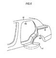
Fig. 6 , in a slide door device for a vehicle disclosed inJP 2008-49946A hinge 91 is installed on the rear end lower portion of adoor opening 90a which is formed on the side of avehicle body 90, and a bodyside center rail 92 is installed in arear quarter panel 90b of the door opening 90a. - Moreover, a slide door (not shown) is inclined with respect to a front-rear direction due to the
hinge 91 while sliding the door side guide roller unit on the bodyside center rail 92, and opens and closes the door opening 90a. Accordingly, also in Reference 2, the body side upper rail which is installed along the upper edge of the door opening 90a or the door side guide roller unit which slides on the body side upper rail is eliminated, and thus, application to a so-called sedan rear door can be realized. - Moreover, a slide door device for a vehicle disclosed in
JP 2009-114782A - However, in Reference 1, since the door side
lower rail 88 and the doorside center rail 89 are exposed to a vehicle interior, the design and structure of the slide door 86 (for example, door trim) are limited. - On the other hand, in
References 2 and 3, since thehinge 91 is used for the opening and closing of the slide door, an opening-closing amount (door stroke) of the slide door is limited, and thus, the hinge cannot be applied to a slide door which needs a large opening-closing amount. Moreover, it is necessary to increase the size of thehinge 91 in order to support the slide door, and to secure a sufficient disposition space for the hinge around the lower portion of the slide door. - A need thus exists for a slide door device for a vehicle capable of securing a sufficient opening-closing amount while alleviating the limitations with respect to the design and structure of the slide door.
- In order to solve the above described problems, according to a first aspect of this disclosure, there is provided a slide door device for a vehicle, including: a body side lower rail which is disposed below a door opening formed on a side of a vehicle body and extends in a front-rear direction of the vehicle; a body side rail which is disposed above the body side lower rail and behind the door opening and extends in the front-rear direction; a door side lower guide roller unit which is connected to a slide door, which opens and closes the door opening, and configured to slide on the body side lower rail; a door side guide roller unit which is connected to the slide door and configured to slide on the body side rail: a door side lower rail which is disposed in a lower portion of the slide door positioned below the floor surface in the door opening and extends in the front-rear direction; and a body side lower guide roller unit which is connected to the lower portion of the door opening and configured to slide on the door side lower rail.
- According to the first aspect, due to the movement in a front-rear direction of the slide door, the door side lower guide roller unit and the door side guide roller unit slide on the body side lower rail and the body side rail respectively and the body side lower guide roller unit slides on the door side lower rail, and thus, the slide door opens and closes the door opening. In this case, the door side lower rail on which the body side lower guide roller unit slides is provided in the slide door However, in the fully closed state where the door opening is closed by the slide door, the door side lower rail is disposed below the floor surface, and thus, is not exposed to the vehicle interior Accordingly, limitations with respect to the design and structure of the slide door (for example, a door trim) can be alleviated. Moreover, since the opening and closing of the door opening by the slide door can be realized by only the sliding operation, for example, compared to a case where a hinge is also used as the related art example, a sufficient opening-closing amount can be secured.
- According to a second aspect of this disclosure, in the slide door device for a vehicle of the first aspect, the body side lower guide roller unit may be disposed behind the door side lower guide roller unit regardless of the opening and closing position of the slide door.
- According to the second aspect, the support position of the slide door in the vehicle body includes both support positions of the door side lower guide roller unit and the door side guide roller unit in the body side lower rail and the body side rail, and a support position of the body side lower guide roller unit in the door side lower rail. In addition, a height difference of the door side guide roller unit is set with respect to the door side lower guide roller unit and the body side lower guide roller unit, and the body side lower guide roller unit is always disposed behind the door side lower guide roller unit. Accordingly, lines which connect each of the two support positions of three support positions necessarily draw a triangle regardless of the opening and closing positions of the slide door. Thereby, the slide door can be supported to the vehicle body in a more stable posture by use of three support positions regardless of the opening and closing positions.
- According to a third aspect of this disclosure, in the slide door device for a vehicle of the second aspect, the door side lower rail may be disposed below the body side lower rail.
- According to the third aspect, as much as the support position of the body side lower guide roller unit in the door side lower rail is disposed below the support position of the door side lower guide roller unit in the body side lower rail, the triangle which is drawn by three support positions is enlarged, and thus, the slide door can be supported to the vehicle body in a more stable posture.
- According to this disclosure, it is possible to provide a slide door device for a vehicle capable of securing a sufficient opening-closing amount while alleviating the limitations with respect to the design and structure of a slide door.
- The foregoing and additional features and characteristics of this disclosure will become more apparent from the following detailed description considered with the reference to the accompanying drawings, wherein:
-
Fig. 1 is a schematic view showing an embodiment of this disclosure; -
Figs. 2A and 2B are cross-sectional views taken along line IIA-IIA and line IIB-IIB ofFig. 1 ; -
Fig. 3 is a cross-sectional view taken along line III-III ofFig. 1 ; -
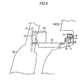
Fig. 4 is a cross-sectional view taken along line IV-IV ofFig. 1 ; -
Fig. 5 is a perspective view showing an example of the related art; and -
Fig. 6 is a perspective view showing another example of the related art. - An embodiment disclosed here will be explained with reference to
Figs. 1 to 4 . - As shown in
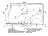
Fig. 1 , in avehicle body 10, a body sidelower rail 11 which is disposed below a door opening 10a formed on the side of the vehicle body extends in a front-rear direction. Moreover, in thevehicle body 10, a bodyside center rail 12, which is disposed in aquarter panel 10b which is positioned behind the door opening 10a in the intermediate portion in the height direction of the door opening 10a, extends in the front-rear direction. The body sidelower rail 11 and the bodyside center rail 12 are parallel to each other. Moreover, in thevehicle body 10, a body side lowerguide roller unit 13 is rotatably connected in the rear lower side of the body sidelower rail 11. - On the other hand, in a
slide door 20 which opens and closes the door opening 10a, a door side lowerguide roller unit 16 which can slide on the body sidelower rail 11 is rotatably connected to the front-side lower portion of the slide door, and a door side centerguide roller unit 17 is rotatably connected to the intermediate portion in the height direction of the rear portion of the slide door. Moreover, in theslide door 20, a door sidelower rail 18, which is disposed below a floor surface F in the door opening 10a and the body sidelower rail 11 and so as to be offset backward to the body sidelower rail 11, extends in the front-rear direction, The door sidelower rail 18 is parallel to the body sidelower rail 11 or the like, and the body side lowerguide roller unit 13 can slide on the door side lower rail. That is, theslide door 20 is supported so as to move in the front-rear direction with respect to thevehicle body 10 via the door side lowerguide roller unit 16, the body sidelower rail 11, and the like. - In addition, according to the movement in the front-rear direction, the door side lower
guide roller unit 16 and the door side centerguide roller unit 17 slide on the body sidelower rail 11 and the bodyside center rail 12 respectively and the body side lowerguide roller unit 13 slides on the door sidelower rail 18, and thus, theslide door 20 opens and closes thedoor opening 10a. The body side lowerguide roller unit 13 is set so as to be always disposed behind the door side lowerguide roller unit 16 regardless of the opening and closing positions of theslide door 20. - Moreover, the support position of the
slide door 20 in thevehicle body 10 includes both support positions P1 and P2 of the door side lowerguide roller unit 16 and the door side centerguide roller unit 17 in the body sidelower rail 11 and the bodyside center rail 12, and a support position P3 of the body side lowerguide roller unit 13 in the door sidelower rail 18. In addition, a height difference of the door side center guide roller unit 17 (support position P2) is set with respect to the door side lowerguide roller unit 16 and the body side lower guide roller unit 13 (support positions P1 and P3), and the body side lower guide roller unit 13 (support position P3) is always disposed behind the door side lower guide roller unit 16 (support position P1). Accordingly, lines which connect two support positions of three support positions P1 to P3 necessarily draw a triangle T regardless of the opening and closing positions of theslide door 20. Particularly, the door sidelower rail 18 is disposed below the body sidelower rail 11, and the larger the separation distance from the door side center guide roller unit 17 (support position P2), the larger the triangle T. InFig. 1 , the support positions P1 to P3 and the triangle T is drawn as representatives of those equivalent to a full closing position of theslide door 20, and support positions P1', P2', and P3' and a triangle T' are also drawn as those equivalent to the full opening position of theslide door 20. - Next, the support structure of the
slide door 20 will be further described. - As shown in
Fig. 2A , the front end portion of the body sidelower rail 11 is bent toward a vehicle interior side. On the other hand, the door side lowerguide roller unit 16 is rotatably connected to anarm member 21 which is secured to the front end portion of theslide door 20, and includes aguide bracket 22 which is formed of a metal plate, for example. As shown inFig. 3 , theguide bracket 22 includes an approximate U shapedconnection portion 22a which is opened so as to face the tip portion of thearm member 21, and is rotatably connected to the arm member 21 (slide door 20) around an axis O1 which extends in the height direction using asupport pin 23 which penetrates theconnection portion 22a which sandwiches the tip portion of thearm member 21. In addition, in theguide bracket 22, theroad roller 24 is pivotally supported by asupport pin 25 in which the axis extends in a vehicle width direction, and aguide roller 26 is pivotally supported by asupport pin 27 in which the axis extends in the height direction. Moreover, as shown inFig. 2A , a pair of guide rollers 26 (and support pins 27) is disposed so as to sandwich theroad roller 24 in the front-rear direction (rail length direction). - As shown in
Fig. 3 , bothguide rollers 26 are mounted so as to roll on the body sidelower rail 11, and thus, the door side lowerguide roller unit 16 guides the movement of theslide door 20 along the body sidelower rail 11, and theroad roller 24 is mounted so as to roll on asupport member 10c of thevehicle body 10, and thus, the door side lower guide roller unit supports the load of theslide door 20. In addition, as described above, the front end portion of the body sidelower rail 11 is bent toward the vehicle interior side. Moreover, the door side lowerguide roller units 16 are disposed in the front end portion and the rear end portion of the body sidelower rail 11 in a fully closed state and a fully opened state of theslide door 20 respectively. Accordingly, the door side lowerguide roller unit 16 which is guided in the body sidelower rail 11 rotates theguide bracket 22 with respect to thearm member 21 around thesupport pin 23, and thus, front and rear movements of theslide door 20 are permitted. - As shown in
Fig. 2B , the front end portion of the bodyside center rail 12 is also bent toward the vehicle interior side. On the other hand, the door side centerguide roller unit 17 includes aguide bracket 32 which is rotatably connected to abracket 31 fixed to the rear end portion of theslide door 20 and is formed of a metal plate, for example. As shown inFig. 4 , theguide bracket 32 includes an approximate U shapedconnection portion 32a which is opened so as to face the tip portion of thebracket 31, and is rotatably connected to the bracket 31 (slide door 20) around anaxis 02 which extends in the height direction using a support pin (not shown) which penetrates theconnection portion 32a along with the tip portion of thebracket 31. In addition, in theguide bracket 32, aroad roller 34 is pivotally supported by asupport pin 35 in which the axis extends in a vehicle width direction, and aguide roller 36 is pivotally supported by asupport pin 37 in which the axis extends in the height direction. Moreover, as shown inFig. 2B , a pair of guide rollers 36 (and support pins 37) is disposed so as to sandwich theroad roller 34 in the front-rear direction (rail length direction). - As shown in
Fig. 4 , both guiderollers 36 are mounted so as to roll on the upper portion of the bodyside center rail 12, and thus, the door side centerguide roller unit 17 guides the movement of theslide door 20 along the bodyside center rail 12. Moreover, since theroad roller 34 is mounted so as to roll on the bottom wall of the bodyside center rail 12, the door side centerguide roller unit 17 supports the load of theslide door 20. In addition, as described above, the front end portion of the bodyside center rail 12 is bent toward the vehicle interior side. Moreover, the door side centerguide roller units 17 are disposed in the front end portion and the rear end portion of the bodyside center rail 12 in the fully closed state and the fully opened state of theslide door 20 respectively. Accordingly, the door side centerguide roller unit 17 which is guided in the bodyside center rail 12 rotates theguide bracket 32 with respect to thebracket 31 around theaxis 02, and thus, front and rear movements of theslide door 20 are permitted. - As shown in
Fig. 2A , the body side lowerguide roller unit 13 includes aguide lever 41 which is rotatably connected to thevehicle body 10 around anaxis 03 extended in the height direction in the rear of the body sidelower rail 11 and is formed of a metal plate, for example. Moreover, as shown inFig. 3 , aguide roller 42 is pivotally supported to the tip portion of theguide lever 41 by asupport pin 43 in which the axis extends in the height direction. Moreover, as shown inFig. 2A , a pair of guide rollers 42 (and support pins 43) is disposed with an interval in the front-rear direction (rail length direction). - On the other hand, the rear end portion of the door side
lower rail 18 is bent toward the outside of a vehicle. As shown inFig. 3 , both guiderollers 42 of the body side lowerguide roller unit 13 are mounted on the door sidelower rail 18 so as to be rolled, and thus, the movement of theslide door 20 along the door sidelower rail 18 is guided. - As described above, the
slide door 20 is guided so as to be approximately flush with the outside surface of the vehicle body 10 (quarter panel 10b) in the fully closed state or to be disposed on the outside surface of the vehicle body 10 (quarter panel 10b) in the opened state. - Next, an operation of the present embodiment will be described,
- According to the movement of the
slide door 20 in the front-rear direction, the door side lowerguide roller unit 16 and the door side centerguide roller unit 17 slide on the body sidelower rail 11 and the bodyside center rail 12 respectively and the body side lowerguide roller unit 13 slides on the door sidelower rail 18, and thus, thedoor opening 10a is opened and closed. In this case, the door sidelower rail 18 on which the body side lowerguide roller unit 13 slides is provided in theslide door 20. However, in the fully closed state where thedoor opening 10a is closed by theslide door 20, the door side lower rail is disposed below the floor surface F, and thus, is not exposed to the vehicle interior. Accordingly, limitations with respect to the design and structure of the slide door 20 (for example, a door trim) are alleviated. Moreover, since the opening and closing of thedoor opening 10a by theslide door 20 can be realized by only the sliding operation, for example, compared to a case where the hinge is also used as the related art example, a sufficient opening-closing amount (so-called door stroke) is secured. - As described in the details above, according to the present embodiment, the following effects are obtained.
- (1) In the present embodiment, in the fully closed state where the
door opening 10a is closed by theslide door 20, the door sidelower rail 18 on which the body side lowerguide roller unit 13 slides is disposed below the floor surface F, and is not exposed to the vehicle interior. Accordingly, limitations with respect to the design and structure of the slide door 20 (for example, a door trim) can be alleviated. - Moreover, since the opening and closing of the
door opening 10a by theslide door 20 can be realized by only the sliding operation, for example, compared to the case where the hinge is also used as the related art example, a sufficient opening-closing amount can be secured. Alternatively, compared to a case where a large hinge is also used as the related art example, limitations to a disposition space which is required around the lower portion of theslide door 20 can be alleviated. - (2) The support position of the
slide door 20 in thevehicle body 10 includes both support positions P1 and P2 (P1' and P2') of the door side lowerguide roller unit 16 and the door side centerguide roller unit 17 in the body sidelower rail 11 and the bodyside center rail 12, and a support position P3 (P3') of the body side lowerguide roller unit 13 in the door sidelower rail 18. Moreover, in the present embodiment, the height difference of the door side centerguide roller unit 17 is set with respect to the door side lowerguide roller unit 16 and the body side lowerguide roller unit 13, and the body side lowerguide roller unit 13 is always disposed behind the door side lowerguide roller unit 16. Accordingly, lines which connect each of the two support positions of three support positions P1 to P3 (P1' to P3') necessarily draw a triangle T (T') regardless of the opening and closing positions of theslide door 20. Thereby, theslide door 20 can be supported to thevehicle body 10 in a more stable posture due to three support positions P1 to P3 (P1' to P3') regardless of the opening and closing positions. - (3) In the present embodiment, the support position P3 (P3') of the body side lower
guide roller unit 13 in the door sidelower rail 18 is disposed below the support position P1 (P1') of the door side lowerguide roller unit 16 in the body sidelower rail 11. Accordingly, as much as the support position P3 (P3') is disposed below the support position P1 (P1'), the triangle T (T') which is drawn by three support positions P1 to P3 (P1' to P3') is enlarged, and thus, theslide door 20 can be supported to thevehicle body 10 in a more stable posture. - (4) In the present embodiment, the body side upper rail which is installed along the upper edge of the
door opening 10a or the door side guide roller unit which slides on the body side upper rail is eliminated, and thus, application to the so-called slide door without a door sash (door frame) can be realized, and limitations with respect to the design and structure of theslide door 20 itself or the roof can be alleviated. In addition, for example, a sedan rear door or the like can be applied as the slide door. - Moreover, the embodiment may be modified as follows.
- In the embodiment, the door side
lower rail 18 is disposed so as to be offset backward with respect to the body sidelower rail 11. However, if interference of the body side lowerguide roller unit 13, the door side lowerguide roller unit 16, or the like can be avoided, the positions in the front-rear direction of the door sidelower rail 18 and the body sidelower rail 11 may be consistent with each other. - In the embodiment, the
guide roller 26 of the door side lowerguide roller unit 16 rolls on the body sidelower rail 11, and the movement of theslide door 20 along the body sidelower rail 11 is guided. On the other hand, instead of theguide roller 26, an appropriate slide body of the door side lowerguide roller unit 16 slides on the body sidelower rail 11, and the movement of theslide door 20 along the body sidelower rail 11 may be guided. - In the embodiment, the
guide roller 42 which rolls on the door sidelower rail 18 is adopted. However, in addition to this, a guide roller which rolls on the outer surface of the door sidelower rail 18 may be separately provided. According to the modification, the movement of theslide door 20 along the door sidelower rail 18 can be more securely guided. - In the embodiment, the
guide roller 42 of the body side lowerguide roller unit 13 rolls on the door sidelower rail 18, and thus, the movement of theslide door 20 along the door sidelower rail 18 is guided. On the other hand, instead of theguide roller 42, an appropriate slide body of the body side lowerguide roller unit 13 slides on the door sidelower rail 18, and the movement of theslide door 20 along the door sidelower rail 18 may be guided. - In the embodiment, the door side
lower rail 18 is disposed below the body sidelower rail 11. However, the door side lower rail may be disposed above the body sidelower rail 11. Moreover, if interference of the body side lowerguide roller unit 13, the door side lowerguide roller unit 16, or the like can be avoided, the positions in the height direction of the door sidelower rail 18 and the body sidelower rail 11 may be consistent with each other. - In the embodiment, if the body
side center rail 12 is disposed above the body sidelower rail 11, the position in the height direction is optional. - In the embodiment, the front and rear positions of the body side lower
guide roller unit 13 and the door side lowerguide roller unit 16 may be reversed according to the opening and closing of theslide door 20. - This disclosure may be applied to a front door, and may also be applied to a rear door of a one box car, minivan car, sedan, wagon, or the like.
- The principles, preferred embodiment and mode of operation of the present invention have been described in the foregoing specification. However, the invention which is intended to be protected is not to be construed as limited to the particular embodiments disclosed. Further, the embodiments described herein are to be regarded as illustrative rather than restrictive. Variations and changes may be made by others, and equivalents employed, without departing from the spirit of the present invention. Accordingly, it is expressly intended that all such variations, changes and equivalents which fall within the spirit and scope of the present invention as defined in the claims, be embraced thereby.
Provided is a slide door device for a vehicle, including: a body side lower rail disposed below a door opening formed on a side of a vehicle body and extends in a front-rear direction; a body side rail disposed above the body side lower rail and behind the door opening and extends in the front-rear direction; a door side lower guide roller unit and a door side guide roller unit connected to a slide door and configured to slide on the body side lower rail and the body side rail respectively; a door side lower rail disposed in a lower portion of the slide door positioned below the floor surface in the door opening and extends in the front-rear direction; and a body side lower guide roller unit connected to the lower portion of the door opening and configured to slide on the door side lower rail.
Claims (3)
- A slide door device for a vehicle, comprising:a body side lower rail which is disposed below a door opening formed on a side of a vehicle body and extends in a front-rear direction of the vehicle;a body side rail which is disposed above the body side lower rail and behind the door opening and extends in the front-rear direction;a door side lower guide roller unit which is connected to a slide door, which opens and closes the door opening, and configured to slide on the body side lower rail;a door side guide roller unit which is connected to the slide door and configured to slide on the body side rail;a door side lower rail which is disposed in a lower portion of the slide door positioned below the floor surface in the door opening and extends in the front-rear direction; anda body side lower guide roller unit which is connected to the lower portion of the door opening and configured to slide on the door side lower rail.
- The slide door device for a vehicle according to claim 1,
wherein the body side lower guide roller unit is disposed behind the door side lower guide roller unit regardless of the opening and closing position of the slide door. - The slide door device for a vehicle according to claim 2,
wherein the door side lower rail is disposed below the body side lower rail.
Applications Claiming Priority (1)
| Application Number | Priority Date | Filing Date | Title |
|---|---|---|---|
| JP2012026457A JP6064332B2 (en) | 2012-02-09 | 2012-02-09 | Sliding door device for vehicle |
Publications (3)
| Publication Number | Publication Date |
|---|---|
| EP2626226A2 true EP2626226A2 (en) | 2013-08-14 |
| EP2626226A3 EP2626226A3 (en) | 2015-12-23 |
| EP2626226B1 EP2626226B1 (en) | 2019-08-14 |
Family
ID=47750440
Family Applications (1)
| Application Number | Title | Priority Date | Filing Date |
|---|---|---|---|
| EP13154568.3A Active EP2626226B1 (en) | 2012-02-09 | 2013-02-08 | Slide door device for vehicle |
Country Status (4)
| Country | Link |
|---|---|
| US (1) | US8701348B2 (en) |
| EP (1) | EP2626226B1 (en) |
| JP (1) | JP6064332B2 (en) |
| CN (1) | CN103241105B (en) |
Families Citing this family (17)
| Publication number | Priority date | Publication date | Assignee | Title |
|---|---|---|---|---|
| JP6155753B2 (en) | 2013-03-27 | 2017-07-05 | アイシン精機株式会社 | Sliding door device for vehicle |
| CN103452412A (en) * | 2013-08-30 | 2013-12-18 | 江苏农林职业技术学院 | Hardware for double sliding door linkage |
| KR20150074806A (en) * | 2013-12-24 | 2015-07-02 | 기아자동차주식회사 | Sliding door for vehicle |
| KR101542981B1 (en) * | 2013-12-27 | 2015-08-07 | 현대자동차 주식회사 | Front door device of vehicle |
| JP6446722B2 (en) | 2014-08-06 | 2019-01-09 | 三井金属アクト株式会社 | Door opener |
| JP6446723B2 (en) | 2014-08-06 | 2019-01-09 | 三井金属アクト株式会社 | Door opener |
| JP6446724B2 (en) * | 2014-08-06 | 2019-01-09 | 三井金属アクト株式会社 | Door opener |
| PL3061685T3 (en) * | 2015-02-24 | 2017-06-30 | Airbus Helicopters Deutschland GmbH | A sliding closing element, in particular a sliding door or a sliding window, for a sliding closing element arrangement of a vehicle, in particular of an aircraft |
| CN107433489A (en) * | 2016-05-25 | 2017-12-05 | 成都与俱科技有限公司 | Mobile door for lathe |
| JP6804344B2 (en) * | 2017-03-08 | 2020-12-23 | ナブテスコ株式会社 | Vehicles with door devices and door devices |
| JP2018203076A (en) * | 2017-06-05 | 2018-12-27 | アイシン精機株式会社 | Guide roller unit and vehicle sliding door device |
| JP2019085819A (en) * | 2017-11-09 | 2019-06-06 | アイシン精機株式会社 | Guide roller unit and slide door device for vehicle |
| JP2019107988A (en) * | 2017-12-18 | 2019-07-04 | アイシン精機株式会社 | Slide door device for vehicle |
| US11220852B2 (en) * | 2019-05-02 | 2022-01-11 | Textron Innovations Inc. | Aircraft having versatile door systems |
| JP2023005271A (en) * | 2021-06-28 | 2023-01-18 | トヨタ自動車株式会社 | Vehicle side part structure |
| US12221815B2 (en) | 2022-03-09 | 2025-02-11 | Honda Motor Co., Ltd. | Door opening prevention system for motor vehicles |
| JP2024098579A (en) * | 2023-01-11 | 2024-07-24 | 本田技研工業株式会社 | Sliding door support mechanism |
Citations (3)
| Publication number | Priority date | Publication date | Assignee | Title |
|---|---|---|---|---|
| JP2003335136A (en) | 2002-05-17 | 2003-11-25 | Mazda Motor Corp | Vehicle side door structure |
| JP2008049946A (en) | 2006-08-28 | 2008-03-06 | Nissan Motor Co Ltd | Sliding door structure for vehicles |
| JP2009114782A (en) | 2007-11-08 | 2009-05-28 | Nissan Motor Co Ltd | Sliding door structure for vehicles |
Family Cites Families (20)
| Publication number | Priority date | Publication date | Assignee | Title |
|---|---|---|---|---|
| BE713215A (en) * | 1967-04-21 | 1968-08-16 | ||
| JPS501229Y1 (en) * | 1970-09-17 | 1975-01-14 | ||
| JPS62110525A (en) * | 1985-11-06 | 1987-05-21 | Daihatsu Motor Co Ltd | Upper supporting mechanism of slide door for automobile |
| JPS6369617U (en) * | 1986-10-27 | 1988-05-11 | ||
| JPH0235819U (en) * | 1988-09-02 | 1990-03-08 | ||
| JPH02234839A (en) * | 1989-03-09 | 1990-09-18 | Mitsubishi Motors Corp | Slide door fitting structure for car |
| JPH04238987A (en) * | 1991-01-09 | 1992-08-26 | Mazda Motor Corp | Slide door for car |
| JPH11189044A (en) * | 1997-12-26 | 1999-07-13 | Nissan Motor Co Ltd | Sliding door for vehicle |
| JP2000016086A (en) * | 1998-07-03 | 2000-01-18 | Central Motor Co Ltd | Slide door locking device and slide door locking method |
| JP2001090426A (en) * | 1999-09-17 | 2001-04-03 | Komatsu Ltd | Sliding door support mechanism |
| US6328374B1 (en) * | 2000-06-21 | 2001-12-11 | Ford Global Technologies, Inc. | Fully-openable slidable vehicle door assembly |
| FR2824357B1 (en) * | 2001-05-04 | 2004-01-23 | Peugeot Citroen Automobiles Sa | ARRANGEMENT OF A SLIDING DOOR OF A MOTOR VEHICLE |
| US6932417B2 (en) * | 2003-09-23 | 2005-08-23 | Gecom Corporation | Vehicle sliding door with extended travel |
| FR2881998B1 (en) * | 2005-02-17 | 2007-04-20 | Renault Sas | STABLE SLIDING DOOR |
| JP2007276551A (en) * | 2006-04-03 | 2007-10-25 | Mitsuba Corp | Vehicle door opening and closing structure |
| FR2900185A1 (en) * | 2006-04-21 | 2007-10-26 | Peugeot Citroen Automobiles Sa | Sliding door frame articulation device for body shell of motor vehicle, has flanges that are in sliding contact with arm which is supported by guiding surfaces to limit inclination of arm towards bottom when arm is stressed towards bottom |
| JP4893144B2 (en) | 2006-08-03 | 2012-03-07 | アイシン精機株式会社 | Power sliding door device for vehicles |
| JP4914841B2 (en) * | 2008-01-09 | 2012-04-11 | 本田技研工業株式会社 | Vehicle sliding door structure |
| DE102008008129A1 (en) * | 2008-02-08 | 2009-08-13 | GM Global Technology Operations, Inc., Detroit | Guide system for sliding door or wing of door of vehicle, particularly passenger car, has two guide or slide units, which comprise guide rail and slide element contacting with guide rail |
| US8308221B2 (en) * | 2009-10-20 | 2012-11-13 | Honda Motor Co., Ltd. | Roller assembly for sliding vehicle closure |
-
2012
- 2012-02-09 JP JP2012026457A patent/JP6064332B2/en not_active Expired - Fee Related
-
2013
- 2013-02-05 CN CN201310045774.1A patent/CN103241105B/en not_active Expired - Fee Related
- 2013-02-08 US US13/762,943 patent/US8701348B2/en not_active Expired - Fee Related
- 2013-02-08 EP EP13154568.3A patent/EP2626226B1/en active Active
Patent Citations (3)
| Publication number | Priority date | Publication date | Assignee | Title |
|---|---|---|---|---|
| JP2003335136A (en) | 2002-05-17 | 2003-11-25 | Mazda Motor Corp | Vehicle side door structure |
| JP2008049946A (en) | 2006-08-28 | 2008-03-06 | Nissan Motor Co Ltd | Sliding door structure for vehicles |
| JP2009114782A (en) | 2007-11-08 | 2009-05-28 | Nissan Motor Co Ltd | Sliding door structure for vehicles |
Also Published As
| Publication number | Publication date |
|---|---|
| JP6064332B2 (en) | 2017-01-25 |
| US20130205671A1 (en) | 2013-08-15 |
| EP2626226A3 (en) | 2015-12-23 |
| CN103241105A (en) | 2013-08-14 |
| US8701348B2 (en) | 2014-04-22 |
| CN103241105B (en) | 2015-09-09 |
| JP2013163414A (en) | 2013-08-22 |
| EP2626226B1 (en) | 2019-08-14 |
Similar Documents
| Publication | Publication Date | Title |
|---|---|---|
| EP2626226B1 (en) | Slide door device for vehicle | |
| US9499031B2 (en) | Rear door device in vehicle | |
| US7621586B2 (en) | Sliding door roller bracket track extension with interlock | |
| US8172296B2 (en) | Parcel shelf structure | |
| US10914108B2 (en) | Opposed type sliding door device of vehicle using planetary gear reducer | |
| US20140203587A1 (en) | Integrated Step and Grab-Handle System for Tailgates | |
| US20090230724A1 (en) | Vehicle Sliding Door Travel Extension System | |
| JP2010083167A (en) | Slide door structure of vehicle | |
| US9493056B2 (en) | Front door device in vehicle | |
| US20140075843A1 (en) | Vehicle door structure | |
| RU2714349C2 (en) | Shutter assembly for cargo space of motor vehicle (embodiments) and motor vehicle | |
| US20130278017A1 (en) | Pillar structure for vehicle body rear portion | |
| WO2014006975A1 (en) | Vehicle with tail gate | |
| JP2014012448A (en) | Vehicle with tailgate | |
| US11787271B2 (en) | Sliding door device for vehicle | |
| US20220106825A1 (en) | Apparatus for Preventing Sliding Door for Vehicle from Swaying | |
| US9297192B2 (en) | Multi-joint slider device | |
| JP5217365B2 (en) | Sliding door structure for vehicles | |
| US8919860B2 (en) | Slide door movement system without center rail | |
| CN115012754A (en) | Lower hinge, mounting structure and vehicle of sliding door | |
| JP2013256202A (en) | Vehicular sliding door structure | |
| US8002327B2 (en) | Motor vehicle | |
| JP2013230779A (en) | Sliding door structure of vehicle | |
| JP3556571B2 (en) | Sliding door support structure | |
| JP3776802B2 (en) | Opening and closing device for vehicle sliding door |
Legal Events
| Date | Code | Title | Description |
|---|---|---|---|
| PUAI | Public reference made under article 153(3) epc to a published international application that has entered the european phase |
Free format text: ORIGINAL CODE: 0009012 |
|
| AK | Designated contracting states |
Kind code of ref document: A2 Designated state(s): AL AT BE BG CH CY CZ DE DK EE ES FI FR GB GR HR HU IE IS IT LI LT LU LV MC MK MT NL NO PL PT RO RS SE SI SK SM TR |
|
| AX | Request for extension of the european patent |
Extension state: BA ME |
|
| PUAL | Search report despatched |
Free format text: ORIGINAL CODE: 0009013 |
|
| AK | Designated contracting states |
Kind code of ref document: A3 Designated state(s): AL AT BE BG CH CY CZ DE DK EE ES FI FR GB GR HR HU IE IS IT LI LT LU LV MC MK MT NL NO PL PT RO RS SE SI SK SM TR |
|
| AX | Request for extension of the european patent |
Extension state: BA ME |
|
| RIC1 | Information provided on ipc code assigned before grant |
Ipc: E05D 15/10 20060101ALI20151119BHEP Ipc: E05D 15/06 20060101ALI20151119BHEP Ipc: B60J 5/06 20060101AFI20151119BHEP |
|
| 17P | Request for examination filed |
Effective date: 20160620 |
|
| RBV | Designated contracting states (corrected) |
Designated state(s): AL AT BE BG CH CY CZ DE DK EE ES FI FR GB GR HR HU IE IS IT LI LT LU LV MC MK MT NL NO PL PT RO RS SE SI SK SM TR |
|
| GRAP | Despatch of communication of intention to grant a patent |
Free format text: ORIGINAL CODE: EPIDOSNIGR1 |
|
| STAA | Information on the status of an ep patent application or granted ep patent |
Free format text: STATUS: GRANT OF PATENT IS INTENDED |
|
| INTG | Intention to grant announced |
Effective date: 20190319 |
|
| GRAS | Grant fee paid |
Free format text: ORIGINAL CODE: EPIDOSNIGR3 |
|
| GRAA | (expected) grant |
Free format text: ORIGINAL CODE: 0009210 |
|
| STAA | Information on the status of an ep patent application or granted ep patent |
Free format text: STATUS: THE PATENT HAS BEEN GRANTED |
|
| AK | Designated contracting states |
Kind code of ref document: B1 Designated state(s): AL AT BE BG CH CY CZ DE DK EE ES FI FR GB GR HR HU IE IS IT LI LT LU LV MC MK MT NL NO PL PT RO RS SE SI SK SM TR |
|
| REG | Reference to a national code |
Ref country code: GB Ref legal event code: FG4D |
|
| REG | Reference to a national code |
Ref country code: CH Ref legal event code: EP Ref country code: AT Ref legal event code: REF Ref document number: 1166600 Country of ref document: AT Kind code of ref document: T Effective date: 20190815 |
|
| REG | Reference to a national code |
Ref country code: IE Ref legal event code: FG4D |
|
| REG | Reference to a national code |
Ref country code: DE Ref legal event code: R096 Ref document number: 602013059040 Country of ref document: DE |
|
| REG | Reference to a national code |
Ref country code: NL Ref legal event code: MP Effective date: 20190814 |
|
| REG | Reference to a national code |
Ref country code: LT Ref legal event code: MG4D |
|
| PG25 | Lapsed in a contracting state [announced via postgrant information from national office to epo] |
Ref country code: SE Free format text: LAPSE BECAUSE OF FAILURE TO SUBMIT A TRANSLATION OF THE DESCRIPTION OR TO PAY THE FEE WITHIN THE PRESCRIBED TIME-LIMIT Effective date: 20190814 Ref country code: PT Free format text: LAPSE BECAUSE OF FAILURE TO SUBMIT A TRANSLATION OF THE DESCRIPTION OR TO PAY THE FEE WITHIN THE PRESCRIBED TIME-LIMIT Effective date: 20191216 Ref country code: LT Free format text: LAPSE BECAUSE OF FAILURE TO SUBMIT A TRANSLATION OF THE DESCRIPTION OR TO PAY THE FEE WITHIN THE PRESCRIBED TIME-LIMIT Effective date: 20190814 Ref country code: HR Free format text: LAPSE BECAUSE OF FAILURE TO SUBMIT A TRANSLATION OF THE DESCRIPTION OR TO PAY THE FEE WITHIN THE PRESCRIBED TIME-LIMIT Effective date: 20190814 Ref country code: NL Free format text: LAPSE BECAUSE OF FAILURE TO SUBMIT A TRANSLATION OF THE DESCRIPTION OR TO PAY THE FEE WITHIN THE PRESCRIBED TIME-LIMIT Effective date: 20190814 Ref country code: FI Free format text: LAPSE BECAUSE OF FAILURE TO SUBMIT A TRANSLATION OF THE DESCRIPTION OR TO PAY THE FEE WITHIN THE PRESCRIBED TIME-LIMIT Effective date: 20190814 Ref country code: NO Free format text: LAPSE BECAUSE OF FAILURE TO SUBMIT A TRANSLATION OF THE DESCRIPTION OR TO PAY THE FEE WITHIN THE PRESCRIBED TIME-LIMIT Effective date: 20191114 Ref country code: BG Free format text: LAPSE BECAUSE OF FAILURE TO SUBMIT A TRANSLATION OF THE DESCRIPTION OR TO PAY THE FEE WITHIN THE PRESCRIBED TIME-LIMIT Effective date: 20191114 |
|
| REG | Reference to a national code |
Ref country code: AT Ref legal event code: MK05 Ref document number: 1166600 Country of ref document: AT Kind code of ref document: T Effective date: 20190814 |
|
| PG25 | Lapsed in a contracting state [announced via postgrant information from national office to epo] |
Ref country code: AL Free format text: LAPSE BECAUSE OF FAILURE TO SUBMIT A TRANSLATION OF THE DESCRIPTION OR TO PAY THE FEE WITHIN THE PRESCRIBED TIME-LIMIT Effective date: 20190814 Ref country code: ES Free format text: LAPSE BECAUSE OF FAILURE TO SUBMIT A TRANSLATION OF THE DESCRIPTION OR TO PAY THE FEE WITHIN THE PRESCRIBED TIME-LIMIT Effective date: 20190814 Ref country code: RS Free format text: LAPSE BECAUSE OF FAILURE TO SUBMIT A TRANSLATION OF THE DESCRIPTION OR TO PAY THE FEE WITHIN THE PRESCRIBED TIME-LIMIT Effective date: 20190814 Ref country code: IS Free format text: LAPSE BECAUSE OF FAILURE TO SUBMIT A TRANSLATION OF THE DESCRIPTION OR TO PAY THE FEE WITHIN THE PRESCRIBED TIME-LIMIT Effective date: 20191214 Ref country code: LV Free format text: LAPSE BECAUSE OF FAILURE TO SUBMIT A TRANSLATION OF THE DESCRIPTION OR TO PAY THE FEE WITHIN THE PRESCRIBED TIME-LIMIT Effective date: 20190814 Ref country code: GR Free format text: LAPSE BECAUSE OF FAILURE TO SUBMIT A TRANSLATION OF THE DESCRIPTION OR TO PAY THE FEE WITHIN THE PRESCRIBED TIME-LIMIT Effective date: 20191115 |
|
| PG25 | Lapsed in a contracting state [announced via postgrant information from national office to epo] |
Ref country code: TR Free format text: LAPSE BECAUSE OF FAILURE TO SUBMIT A TRANSLATION OF THE DESCRIPTION OR TO PAY THE FEE WITHIN THE PRESCRIBED TIME-LIMIT Effective date: 20190814 |
|
| PG25 | Lapsed in a contracting state [announced via postgrant information from national office to epo] |
Ref country code: RO Free format text: LAPSE BECAUSE OF FAILURE TO SUBMIT A TRANSLATION OF THE DESCRIPTION OR TO PAY THE FEE WITHIN THE PRESCRIBED TIME-LIMIT Effective date: 20190814 Ref country code: IT Free format text: LAPSE BECAUSE OF FAILURE TO SUBMIT A TRANSLATION OF THE DESCRIPTION OR TO PAY THE FEE WITHIN THE PRESCRIBED TIME-LIMIT Effective date: 20190814 Ref country code: AT Free format text: LAPSE BECAUSE OF FAILURE TO SUBMIT A TRANSLATION OF THE DESCRIPTION OR TO PAY THE FEE WITHIN THE PRESCRIBED TIME-LIMIT Effective date: 20190814 Ref country code: DK Free format text: LAPSE BECAUSE OF FAILURE TO SUBMIT A TRANSLATION OF THE DESCRIPTION OR TO PAY THE FEE WITHIN THE PRESCRIBED TIME-LIMIT Effective date: 20190814 Ref country code: EE Free format text: LAPSE BECAUSE OF FAILURE TO SUBMIT A TRANSLATION OF THE DESCRIPTION OR TO PAY THE FEE WITHIN THE PRESCRIBED TIME-LIMIT Effective date: 20190814 Ref country code: PL Free format text: LAPSE BECAUSE OF FAILURE TO SUBMIT A TRANSLATION OF THE DESCRIPTION OR TO PAY THE FEE WITHIN THE PRESCRIBED TIME-LIMIT Effective date: 20190814 |
|
| PGFP | Annual fee paid to national office [announced via postgrant information from national office to epo] |
Ref country code: DE Payment date: 20200129 Year of fee payment: 8 |
|
| PG25 | Lapsed in a contracting state [announced via postgrant information from national office to epo] |
Ref country code: CZ Free format text: LAPSE BECAUSE OF FAILURE TO SUBMIT A TRANSLATION OF THE DESCRIPTION OR TO PAY THE FEE WITHIN THE PRESCRIBED TIME-LIMIT Effective date: 20190814 Ref country code: SK Free format text: LAPSE BECAUSE OF FAILURE TO SUBMIT A TRANSLATION OF THE DESCRIPTION OR TO PAY THE FEE WITHIN THE PRESCRIBED TIME-LIMIT Effective date: 20190814 Ref country code: IS Free format text: LAPSE BECAUSE OF FAILURE TO SUBMIT A TRANSLATION OF THE DESCRIPTION OR TO PAY THE FEE WITHIN THE PRESCRIBED TIME-LIMIT Effective date: 20200224 Ref country code: SM Free format text: LAPSE BECAUSE OF FAILURE TO SUBMIT A TRANSLATION OF THE DESCRIPTION OR TO PAY THE FEE WITHIN THE PRESCRIBED TIME-LIMIT Effective date: 20190814 |
|
| REG | Reference to a national code |
Ref country code: DE Ref legal event code: R097 Ref document number: 602013059040 Country of ref document: DE |
|
| PGFP | Annual fee paid to national office [announced via postgrant information from national office to epo] |
Ref country code: FR Payment date: 20200113 Year of fee payment: 8 |
|
| PLBE | No opposition filed within time limit |
Free format text: ORIGINAL CODE: 0009261 |
|
| STAA | Information on the status of an ep patent application or granted ep patent |
Free format text: STATUS: NO OPPOSITION FILED WITHIN TIME LIMIT |
|
| PG2D | Information on lapse in contracting state deleted |
Ref country code: IS |
|
| 26N | No opposition filed |
Effective date: 20200603 |
|
| PG25 | Lapsed in a contracting state [announced via postgrant information from national office to epo] |
Ref country code: SI Free format text: LAPSE BECAUSE OF FAILURE TO SUBMIT A TRANSLATION OF THE DESCRIPTION OR TO PAY THE FEE WITHIN THE PRESCRIBED TIME-LIMIT Effective date: 20190814 |
|
| REG | Reference to a national code |
Ref country code: CH Ref legal event code: PL |
|
| GBPC | Gb: european patent ceased through non-payment of renewal fee |
Effective date: 20200208 |
|
| REG | Reference to a national code |
Ref country code: BE Ref legal event code: MM Effective date: 20200229 |
|
| PG25 | Lapsed in a contracting state [announced via postgrant information from national office to epo] |
Ref country code: MC Free format text: LAPSE BECAUSE OF FAILURE TO SUBMIT A TRANSLATION OF THE DESCRIPTION OR TO PAY THE FEE WITHIN THE PRESCRIBED TIME-LIMIT Effective date: 20190814 Ref country code: LU Free format text: LAPSE BECAUSE OF NON-PAYMENT OF DUE FEES Effective date: 20200208 |
|
| PG25 | Lapsed in a contracting state [announced via postgrant information from national office to epo] |
Ref country code: CH Free format text: LAPSE BECAUSE OF NON-PAYMENT OF DUE FEES Effective date: 20200229 Ref country code: LI Free format text: LAPSE BECAUSE OF NON-PAYMENT OF DUE FEES Effective date: 20200229 |
|
| PG25 | Lapsed in a contracting state [announced via postgrant information from national office to epo] |
Ref country code: GB Free format text: LAPSE BECAUSE OF NON-PAYMENT OF DUE FEES Effective date: 20200208 Ref country code: IE Free format text: LAPSE BECAUSE OF NON-PAYMENT OF DUE FEES Effective date: 20200208 |
|
| PG25 | Lapsed in a contracting state [announced via postgrant information from national office to epo] |
Ref country code: BE Free format text: LAPSE BECAUSE OF NON-PAYMENT OF DUE FEES Effective date: 20200229 |
|
| REG | Reference to a national code |
Ref country code: DE Ref legal event code: R119 Ref document number: 602013059040 Country of ref document: DE |
|
| PG25 | Lapsed in a contracting state [announced via postgrant information from national office to epo] |
Ref country code: FR Free format text: LAPSE BECAUSE OF NON-PAYMENT OF DUE FEES Effective date: 20210228 Ref country code: DE Free format text: LAPSE BECAUSE OF NON-PAYMENT OF DUE FEES Effective date: 20210901 |
|
| PG25 | Lapsed in a contracting state [announced via postgrant information from national office to epo] |
Ref country code: MT Free format text: LAPSE BECAUSE OF FAILURE TO SUBMIT A TRANSLATION OF THE DESCRIPTION OR TO PAY THE FEE WITHIN THE PRESCRIBED TIME-LIMIT Effective date: 20190814 Ref country code: CY Free format text: LAPSE BECAUSE OF FAILURE TO SUBMIT A TRANSLATION OF THE DESCRIPTION OR TO PAY THE FEE WITHIN THE PRESCRIBED TIME-LIMIT Effective date: 20190814 |
|
| PG25 | Lapsed in a contracting state [announced via postgrant information from national office to epo] |
Ref country code: MK Free format text: LAPSE BECAUSE OF FAILURE TO SUBMIT A TRANSLATION OF THE DESCRIPTION OR TO PAY THE FEE WITHIN THE PRESCRIBED TIME-LIMIT Effective date: 20190814 |