EP2626000A1 - Endoscope adapter, endoscope processor, and endoscope system - Google Patents
Endoscope adapter, endoscope processor, and endoscope system Download PDFInfo
- Publication number
- EP2626000A1 EP2626000A1 EP11862001.2A EP11862001A EP2626000A1 EP 2626000 A1 EP2626000 A1 EP 2626000A1 EP 11862001 A EP11862001 A EP 11862001A EP 2626000 A1 EP2626000 A1 EP 2626000A1
- Authority
- EP
- European Patent Office
- Prior art keywords
- endoscope
- adjustment
- adapter
- processor
- parameters
- Prior art date
- Legal status (The legal status is an assumption and is not a legal conclusion. Google has not performed a legal analysis and makes no representation as to the accuracy of the status listed.)
- Granted
Links
Images




Classifications
-
- H—ELECTRICITY
- H04—ELECTRIC COMMUNICATION TECHNIQUE
- H04N—PICTORIAL COMMUNICATION, e.g. TELEVISION
- H04N7/00—Television systems
- H04N7/18—Closed-circuit television [CCTV] systems, i.e. systems in which the video signal is not broadcast
-
- A—HUMAN NECESSITIES
- A61—MEDICAL OR VETERINARY SCIENCE; HYGIENE
- A61B—DIAGNOSIS; SURGERY; IDENTIFICATION
- A61B1/00—Instruments for performing medical examinations of the interior of cavities or tubes of the body by visual or photographical inspection, e.g. endoscopes; Illuminating arrangements therefor
- A61B1/00002—Operational features of endoscopes
- A61B1/00004—Operational features of endoscopes characterised by electronic signal processing
- A61B1/00006—Operational features of endoscopes characterised by electronic signal processing of control signals
-
- A—HUMAN NECESSITIES
- A61—MEDICAL OR VETERINARY SCIENCE; HYGIENE
- A61B—DIAGNOSIS; SURGERY; IDENTIFICATION
- A61B1/00—Instruments for performing medical examinations of the interior of cavities or tubes of the body by visual or photographical inspection, e.g. endoscopes; Illuminating arrangements therefor
- A61B1/00002—Operational features of endoscopes
- A61B1/00059—Operational features of endoscopes provided with identification means for the endoscope
-
- A—HUMAN NECESSITIES
- A61—MEDICAL OR VETERINARY SCIENCE; HYGIENE
- A61B—DIAGNOSIS; SURGERY; IDENTIFICATION
- A61B1/00—Instruments for performing medical examinations of the interior of cavities or tubes of the body by visual or photographical inspection, e.g. endoscopes; Illuminating arrangements therefor
- A61B1/00112—Connection or coupling means
- A61B1/00121—Connectors, fasteners and adapters, e.g. on the endoscope handle
-
- A—HUMAN NECESSITIES
- A61—MEDICAL OR VETERINARY SCIENCE; HYGIENE
- A61B—DIAGNOSIS; SURGERY; IDENTIFICATION
- A61B1/00—Instruments for performing medical examinations of the interior of cavities or tubes of the body by visual or photographical inspection, e.g. endoscopes; Illuminating arrangements therefor
- A61B1/04—Instruments for performing medical examinations of the interior of cavities or tubes of the body by visual or photographical inspection, e.g. endoscopes; Illuminating arrangements therefor combined with photographic or television appliances
- A61B1/045—Control thereof
Definitions
- the present invention relates to an adapter for endoscope, a processor for endoscope and an endoscope system.
- an endoscope system has been widely used in a medical field and an industrial field.
- the endoscope system makes it possible to perform observation, image recording and the like of an endoscopy target site by inserting an endoscope insertion portion of the endoscope system into an inside of a patient's body cavity or into an inside of an endoscopy object.
- the processor When a detachable endoscope is connected to a processor, the processor generates a driving signal for driving an image pickup device provided at a distal end portion of the endoscope insertion portion, performs image processing of an image signal, which is a video signal from the image pickup device, and displays an endoscopic image on a monitor. At that time, the processor cannot generate an appropriate endoscopic image without performing white balance adjustment of the endoscopic image. That is, the processor can generate an appropriate endoscopic image and output the endoscopic image on the monitor by obtaining various parameters for adjustment including a coefficient for white balance adjustment and the like, driving the endoscope on the basis of the parameters for adjustments and performing image processing of a received image signal.
- endoscope apparatus which enables an endoscope holding parameters for adjustment, such as various gains, as respective resistance values of variable resistors to be connected to a processor via an adapter.
- the processor reads the resistance value via the adapter, discriminates parameters for adjustment from the resistance value, and performs driving and image processing of each endoscope on the basis of the discriminated various parameters for adjustment.
- a processor identifies the endoscope on the basis of identification information about the endoscope connected, and performs various adjustments such as white balance adjustment if the identified endoscope is an endoscope connected for the first time.
- the processor obtains the various parameters for adjustment then and stores the various parameters for adjustment into the nonvolatile memory of the endoscope.
- the processor judges whether or not the endoscope is an endoscope which has been previously connected when the endoscope is connected. If the endoscope is an endoscope which has been previously connected, the processor reads the various parameters for adjustment from the endoscope and uses the parameters for driving an image pickup device, image processing of an image signal and the like. Thus, after performing white balance adjustment and the like once, a user is not required to perform adjustment works such as white balance adjustment each time he uses the endoscope afterwards.
- the adapter according to the proposal above is used for enabling another type of endoscope, which is not a new type of endoscope, to be used by connecting the other type of endoscope to the processor corresponding to the new type of endoscope.
- analog-digital conversion can be performed on parameters for adjustment included in an endoscope and the parameters for adjustment can be transmitted to the processor, but adjustment at the time that the endoscope and the adapter is combined is not taken into consideration.
- An object of the present invention is to provide an adapter for endoscope, an endoscope system, and a processor for endoscope, which enable an endoscope connected to a processor using an adapter to be used with usability similar to that in a case of using an endoscope which stores various parameters for adjustment in a built-in nonvolatile memory.
- An adapter for endoscope is an adapter for endoscope connecting an endoscope provided with an image pickup device which analog signals are inputted to and outputted from and a processor which digital signals are inputted to and outputted from; and the adapter is provided with: an image pickup device driving signal generation circuit generating a driving signal for driving the image pickup device on the basis of a driving control signal from the processor; an image signal output circuit converting an analog image signal from the image pickup device to a digital image signal in a serial signal format and outputting the digital image signal to the processor; an endoscope identification information reception circuit receiving endoscope identification information which is identification information about the endoscope; an adapter identification information storage section storing adapter identification information which is identification information about the adapter for endoscope; a parameter-for-adjustment storage section storing parameters for adjustment; and a control section performing control to store the parameters for adjustment received from the processor into the parameter-for-adjustment storage section according to a command to write the parameters for adjustment from the processor, and read
- a processor for endoscope is a processor capable of inputting and outputting digital signals to and from an adapter for endoscope to which an endoscope is connectable, the endoscope being provided with an image pickup device which analog signals are inputted to and outputted from, wherein the adapter for endoscope comprises: an image pickup device driving signal generation circuit generating a driving signal for driving the image pickup device on the basis of a driving control signal from the processor; an image signal output circuit converting an analog image signal from the image pickup device to a digital image signal in a serial signal format and outputting the digital image signal to the processor; an endoscope identification information reception circuit receiving endoscope identification information which is identification information about the endoscope; an adapter identification information storage section storing adapter identification information which is identification information about the adapter for endoscope; a parameter-for-adjustment storage section storing parameters for adjustment; and a control section performing control to store the parameters for adjustment received from the processor into the parameter-for-adjustment storage section according to a command
- An endoscope system is an endoscope system comprising: an adapter for endoscope to which an endoscope is connectable, the endoscope being provided with an image pickup device which analog signals are inputted to and outputted from; and a processor which digital signals are inputted to and outputted from, wherein the adapter for endoscope comprises: an image pickup device driving signal generation circuit generating a driving signal for driving the image pickup device on the basis of a driving control signal from the processor; an image signal output circuit converting an analog image signal from the image pickup device to a digital image signal in a serial signal format and outputting the digital image signal to the processor; an endoscope identification information reception circuit receiving endoscope identification information which is identification information about the endoscope; an adapter identification information storage section storing adapter identification information which is identification information about the adapter for endoscope; a parameter-for-adjustment storage section storing parameters for adjustment; and a control section performing control to store the parameters for adjustment received from the processor into the parameter-for-adjust
- Fig. 1 is a configuration diagram showing a configuration of an endoscope system according to the present embodiment.
- An endoscope system 1 includes a processor 11 which digital signals are inputted to or outputted from to perform image processing and the like, a light source apparatus 12, and a monitor 13 as a display apparatus.
- the processor 11 and the light source apparatus 12 are connected via a cable 14, and the processor 11 and the monitor 13 are connected via a cable 15.
- two types of endoscopes 21 and 31 are connectable to the light source apparatus 12.
- the endoscope 21 of the first type is configured to include a flexible or rigid insertion portion 22, an operation section 23, a cable 24 and a connector 25 connected to the proximal end of the cable 24.
- An image pickup device 22a is mounted inside the distal end portion of the insertion portion 22.
- the endoscope 21 is attachable to and detachable from a connector portion 12a of the light source apparatus 12 via the connector 25.
- the connector 25 has a light guide 26, which is a protruding end portion of a light guide for illumination, and an electrical contact section 27 which includes multiple contact points for various electrical signals.
- the connector portion 12a has an electrical contact section 12b having multiple contact points, which corresponds to the contact section 27, and a light guide connector portion (not shown) for connecting a light guide 12c corresponding to the light guide 26.
- connection portions for an air/water feeding function the connection portions for air/water feeding are not shown, and description thereof is omitted.
- the connector portion 12a is configured so that, when the connector 25 is connected to the connector portion 12a of the light source apparatus 12, illumination light from a lamp (not shown) in the light source apparatus 12 is condensed on an end face 26a of the light guide 26, and the contact section 27 of the connector 25 and the contact section 12b of the connector portion 12 are in contact with each other.
- the connector 25 when the connector 25 is connected to the connector portion 12a of the light source apparatus 12, light from the light source apparatus 12 passes through the light guide 26 of the connector 25 and a light guide inserted through the endoscope 21 and is radiated from the distal end of the insertion portion 22 as illumination light. Furthermore, by connecting the connector 25 to the connector portion 12a of the light source apparatus 12, driving control of the image pickup device 22a arranged at the distal end of the insertion portion 22 from the processor 11 and reception of an image signal, which is a video signal from the image pickup device 22a, at the processor 11 become possible via the contact section 27. Furthermore, an operation signal of the operation section 23 is also transmitted to the processor 11 via the contact section 27.
- the endoscope 21 has a flash memory 25a, which is a nonvolatile memory for storing an identifier specific to the endoscope 21 (hereinafter referred to as endoscope ID information) and various parameter data for adjustment, for example, in the connector 25.
- the endoscope ID information may be stored in a ROM provided separately.
- the processor 11 executes white balance processing, acquires various parameters for adjustment and stores the various parameters for adjustment into the flash memory 25a of the endoscope 21.
- the processor 11 stores endoscope ID information about the endoscope 21 for which the white balance adjustment has been performed.
- the processor 11 can read the endoscope ID information about the endoscope 21 and judge whether the endoscope 21 has been connected for the first time or has been already connected in the past, on the basis of the read endoscope ID information.
- the connector 25 of the endoscope 21 can be connected to the light source apparatus 12 by a one-touch operation, and parameters for adjustment, such as a coefficient for white balance adjustment, are stored in the flash memory 25a of the endoscope 21. Then, when the endoscope 21 is connected to the processor 11 again, the processor 11 can generate a driving clock signal for driving the image pickup device 22a and perform image processing, using the parameters for adjustment stored in the flash memory 25a of the endoscope 21, and, therefore, the user need not perform adjustment work.
- parameters for adjustment such as a coefficient for white balance adjustment
- the endoscope 31 of the second type is configured to include an insertion portion 32, an operation section 33, a cable 34 and a connector 35 connected to the proximal end of the cable 34.
- An image pickup device 32a which analog signals are inputted to or outputted from is mounted inside the distal end portion of the insertion portion 32.
- an adapter for endoscope (hereinafter referred to as an adapter) 41 is configured such that it is connectable, to the connector 35 of the endoscope 31, and, therefore, the endoscope 31 can be detachably connected to the connector portion 12a of the light source apparatus 12 via the adapter 41 by fitting the adapter 41 to the connector 35.
- the adapter 41 includes a ROM 41a which stores ID information about the adapter 41 (hereinafter referred to as adapter ID information) and a flash memory 41b which is a nonvolatile memory capable of storing various parameters for adjustment.
- the endoscope 31 of the second type also has endoscope ID information, but the endoscope 31 is endoscope of a type which cannot store parameters for adjustment such as a coefficient for white balance adjustment, in combination with the processor 11.
- the endoscope 31 of the second type is an old type of endoscope, and has originally been used being connected to another light source apparatus and another processor. That is, though the endoscope 31 of the second type is used in combination with another processor, it can be used in combination with the new processor 11 for the endoscope 21 of the first type by using the adapter 41.
- Fig. 2 is a diagram for illustrating a configuration of the adapter 41.
- the adapter 41 is configured such that it is connectable to the connector 35 of the endoscope 31.
- the adapter 41 is configured such that it is also connectable to the connector portion 12a of the light source apparatus 12. Therefore, the adapter 41 has a light guide 42, which is a protruding end portion of a light guide for illumination, and an electrical contact section 43 which includes multiple contact points for various electrical signals. That is, the adapter 41 is an adapter for endoscope which connects the endoscope 31 provided with the image pickup device 32a which alog signals are inputted to and outputted from and the processor 11 which digital signals are inputted to and outputted from.
- the configuration of the contact section 43 is similar to that of the contact section 27 of the connector 25 of the endoscope 21.
- the adapter 41 is configured such that, when the connector 35 is connected therewith, an end face 36a of a light guide 36 protruding on the proximal end side of the connector 35 is in contact with an end face 42a on the distal end side of the light guide 42 of the adapter 41.
- the adapter 41 is connected to the connector portion 12a of the light source apparatus 12, illumination light from the lamp (not shown) in the light source apparatus 12 is condensed on the proximal end of the light guide 42. Therefore, the light guide 42 is a light transmission member which transmits light from the light source apparatus 12 to the light guide 36 of the endoscope 31.
- the adapter 41 has an electrical connector 44 for connecting to an electrical connector 35a of the connector 35.
- the connector 44 is provided at the end portion of a cable 45 extended from the adapter 41.
- the adapter 41 includes a circuit board 51 on which various circuits to be described later are mounted.
- the circuit board 51 is connected to the cable 45 via various signal lines 51a and connected to the contact section 43 via various signal lines 51b.
- the processor 11 can provide a driving signal to the image pickup device 32a arranged at the distal end of the insertion portion 32 and receive an image signal, which is a video signal from the image pickup device 32a, via the electrical connectors 35a and 44, the cable 45 and the contact section 43. Furthermore, an operation signal of the operation section 33 is also transmitted to the processor 11 via the contact section 43.
- the circuit board 51 and the endoscope 31 are connected via the various signal lines 51a, the cable 45, and the electrical connectors 44 and 35a, and, furthermore, the circuit board 51 and the processor 11 are connected via the various signal lines 51b, the contact sections 43 and 12b, and the cable 14.
- the processor 11 can not only connect the endoscope 21 of the first type but also connect the endoscope 31 of the second type by using the adapter 41.
- the endoscope 21 of the first type includes the flash memory 25a capable of storing ID information specific to the endoscope 21 of the first type and various parameters for adjustment inside the endoscope 21, and the processor 11 can read the information in the memory and write various parameters for adjustment.
- the user when using multiple endoscopes 21 in combination with the processor 11, the user is required to perform various adjustments at the time of using each endoscope for the first time, but he does not have to perform any adjustment at all at the time of using the endoscope the second and succeeding times. Therefore, usability of using a combination of multiple endoscopes 21 and the processor 11 is good for the user.
- the endoscope 31 of the second type has ID information on the basis of a resistance value of a variable resistor or the like, the endoscope 31 is a type of endoscope which cannot store various parameters for adjustment in combination with the processor 11.
- the endoscope 31 of the second type is originally used in combination with another processor, it is necessary to perform various adjustment works each time of using the endoscope 31, and the processor has to acquire information about various parameters for adjustment, which is troublesome for the user.
- the user can use the endoscope 31 of the second type with usability similar to that of the endoscope 21 of the first type.
- Fig. 3 is a block configuration diagram of the board 51 of the adapter 41.
- the board 51 includes a field programmable gate array (hereinafter referred to as an FPGA) 61 which executes various processes, the ROM 41a and the flash memory 41 b.
- FPGA field programmable gate array
- the various signal lines 51a are connected to signal lines 71, 72 and 73 implemented on the board 51, respectively.
- the signal line 71 is a signal line for receiving an image signal from the image pickup device of the endoscope 31.
- the signal line 72 is a signal line for outputting a driving pulse signal which drives the image pickup device.
- the signal line 73 is a signal line for receiving an analog signal corresponding to endoscope ID information about the endoscope 31.
- the board 51 includes: a buffer circuit 71a which is connected to the signal line 71 and which receives an image signal; an analog-digital converter (hereinafter referred to as an A/D converter) 7 1 b connected to the buffer circuit 71 a; a buffer circuit 73a which is connected to the signal line 73 and which receives an analog signal corresponding to endoscope ID information; and an A/D converter 73b connected to the buffer circuit 73a.
- the buffer circuit 73a, the A/D converter 73b and an I/F 96 constitute an endoscope identification information reception circuit which receives endoscope identification information, which is identification information about the endoscope 31.
- the A/D converter 73b is unnecessary.
- the various signal lines 51b are connected to a differential output circuit 81, a differential input circuit 82, a differential output circuit 83 and a differential input circuit 84 which are implemented on the board 51, respectively.
- the differential output circuit 81 is a circuit for outputting an image signal from the image pickup device 32a of the endoscope 31 to the processor 11 by a differential signal.
- the differential input circuit 82 is a circuit for inputting a driving clock signal from the processor 11 to the image pickup device 32a of the endoscope 31 by a differential signal.
- the differential output circuit 83 is a circuit for outputting data read from the ROM 41a and the flash memory 41b to the processor 11 by a differential signal.
- the differential input circuit 84 is a circuit for receiving various commands from the processor 11 and data from the processor 11 to be written into the flash memory 41 b by a differential signal.
- the FPGA 61 executes a process of converting a parallel image signal from the signal line 71 to a serial image signal and outputting the serial image signal to the differential output circuit 81 and a process of performing single conversion of a driving clock signal in a differential signal from the differential input circuit 82 to output a driving pulse signal.
- the FPGA 61 executes a process of inputting ID information about the endoscope 31 and outputting the ID information to the differential output circuit 83, a process of converting endoscope ID information about the endoscope 31, adapter ID information in the ROM 14a and various parameters for adjustment in the flash memory 41b to serial signals and outputting the signals to the differential output circuit 83, according to a various information reading command from the differential input circuit 84, and a process of writing the various parameters for adjustment to the flash memory 41b according to a various information writing command from the differential input circuit 84.
- Adapter ID information is stored in the ROM 41a. Therefore, the ROM 41a is an adapter identification information storage section which stores adapter identification information, which is identification information about the adapter 41.
- driving pulse generation information such as the pulse period and voltage of a driving signal corresponding to the kind of the image pickup device 32a of the endoscope 31 of the second type, is stored. This is because the pulse period and the like of a driving signal differ according to the kind, specifications and the like of the image pickup device 32a.
- the kinds of the image pickup devices 32a mounted on the endoscopes 31 are such that the period, voltage and the like of a driving signal is the same, the adapter 41 may not hold the driving pulse generation information.
- the processor 11 may hold the driving pulse generation information so as to provide corresponding driving pulse generation information for the adapter 41 on the basis of endoscope ID information from the adapter 41.
- adapter ID information may be stored in the flash memory 41b.
- Fig. 4 is a block configuration diagram of the FPGA 61.
- the FPGA 61 includes a control section 91, a driver section 92, parallel-serial converters (hereinafter referred to as a P/S converters) 93 and 94, a serial-parallel converter (hereinafter referred to as an S/P converter) 95 and the interface (I/F) 96.
- a P/S converters parallel-serial converters
- S/P converter serial-parallel converter
- the control section 91 reads driving pulse generation information corresponding to the image pickup device 32a of the connected endoscope 31 on the basis of endoscope ID information to control the driver section 92.
- the control section 91 performs a process of transmitting endoscope ID information about the endoscope 31, adapter ID information and various parameters for adjustment to the processor 11 according to a transmission request command from the processor 11 and performing writing to the flash memory 41b according to a various-parameters-for-adjustment writing request command from the processor 11.
- control section 91 executes a process of reading parameters for adjustment corresponding to endoscope ID information about the connected endoscope 31 from the flash memory 41 b and transmitting the parameters for adjustment to the processor 11.
- control section 91 is a control section which performs control so as to store various parameters for adjustment received from the processor 11 into the flash memory 41 b according to a parameters-for-adjustment writing command from the processor 11, and read the various parameters for adjustment stored in the flash memory 41b and output the parameters for adjustment to the processor 11 according to a various-parameters-for-adjustment reading command from the processor 11.
- the driver section 92 is connected to the differential input circuit 82.
- the driver section 92 inputs a driving clock signal from the processor 11, performs single conversion of the signal and outputs a parallel driving pulse signal to the endoscope 31.
- the driver section 92 constitutes an image pickup device driving signal generation circuit which generates a driving pulse signal, which is a driving signal for driving the image pickup device 32a, on the basis of a driving clock signal, which is a driving control signal from the processor 11.
- the P/S converter 93 is connected to the differential output circuit 81.
- the P/S converter 93 inputs a parallel image signal from the image pickup device 32a, converts the parallel signal to a serial signal and outputs the serial signal to the processor 11. Therefore, the A/D converter 73b and the P/S converter 93 constitute an image signal output circuit which converts an analog image signal from the image pickup device 32a to a digital image signal in a serial signal format and outputs the digital image signal to the processor 11.
- the P/S converter 94 is connected to the differential output circuit 83.
- the control section 91 converts endoscope ID information, adapter ID information and various parameters for adjustment to serial signals and outputs the serial signals to the processor 11.
- the S/P converter 95 is connected to the differential input circuit 84.
- the S/P converter 95 inputs various commands and various data from the processor 11, converts the commands and data to parallel signals and outputs the parallel signals to the control section 91.
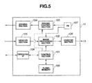
- Fig. 5 is a block configuration diagram of the processor 11.
- the processor 11 is configured to include: a control section 101 having a central processing unit (hereinafter referred to as a CPU), an image processing section 102, a driving control section 103, a driving section 104, a video front end section (hereinafter referred to as a video FE section) 105, a video back end section (hereinafter referred to as a video BE section) 106, a timing generator (hereinafter referred to as a TG) 107, a communication interface (hereinafter referred to as a communication I/F) 108 and a flash memory 109 which is a nonvolatile memory.
- a control section 101 having a central processing unit (hereinafter referred to as a CPU), an image processing section 102, a driving control section 103, a driving section 104, a video front end section (hereinafter referred to as a video FE section) 105, a video back end section (hereinafter referred to as a video BE section) 106, a
- the control section 101 controls the whole processor 11 so as to realize various functions of the endoscope system 1 corresponding to operation instructions by the user.
- a white balance adjustment function is included in the various functions.
- the control section 101 performs a process of controlling the image processing section 102 and the driving control section 103 on the basis of various parameters for adjustment obtained as a result of white balance processing.
- the video FE section 105 receives an image signal of an endoscopic image received via the connector portion 12a of the light source apparatus 12 and provides the image signal to the image processing section 102.
- the image processing section 102 performs predetermined image processing of the image signal from the video FE section 105 using various parameters for adjustment from the control section 101 and outputs the image-processed image signal to the video BE section 106.
- the video BE section 106 generates an analog image signal and outputs the analog image signal to the monitor 13.
- the driving control section 103 generates a driving clock signal of each of image pickup devices of endoscopes using the various parameters for adjustment from the control section 101 and outputs the driving clock signal via the driving section 104.
- the communication I/F 108 is an interface circuit for communication of various data such as an operation signal, endoscope ID information, adapter ID information and parameters for adjustment.
- the control section 101 performs data communication with the endoscope 21 and the adapter 41 via the communication I/F 108.
- the flash memory 109 includes a table for storing adjusted endoscope information about endoscopes 21 of the first type and a table for storing adjusted combination information about combinations of endoscope 31 of the second type and adapter 41. Configurations of the tables will be described later.
- Fig. 6 is a flowchart showing an example of a flow of a parameter-for-adjustment acquisition and writing process of the processor 11.
- the process in Fig. 6 is executed.
- the process in Fig. 6 is performed by the CPU of the control section 101 executing a predetermined program stored in a ROM or the like not shown.
- the processor 11 can receive a signal from the connector portion 12a of the light source apparatus 12.
- the control section 101 When the processor 11 is powered on, the control section 101 outputs a predetermined command to read ID information in order to judge which of the endoscope 21 and the adapter 41 is connected to the connector portion 12a (S1).
- the reading of the ID information includes a case of reading endoscope ID information about the endoscope 21 and a case of reading adapter ID information about the adapter 41 and endoscope ID information about the endoscope 31.
- the endoscope 21 receives the command for reading ID information from the processor 11, the endoscope 21 reads endoscope ID information stored in the memory 25a and transmits the endoscope ID information to the processor 11. If the adapter 41 receives the command for reading ID information from the processor 11, the FPGA 61 transmits adapter ID information stored in the memory 41a to the processor 11. The FPGA 61 also reads the resistance value of a resistor for identification of the connected endoscope 31, via the buffer circuit 73a, converts the resistance value to a digital signal in the A/D converter 73b and transmits the digital signal to the processor 11 as endoscope ID information about the endoscope 31.
- the endoscope ID information about the endoscope 31 may be obtained by recording the endoscope ID information about the endoscope 31 to a ROM provided in the endoscope 31 and providing means for reading information in the ROM for the adapter 41.
- the control section 101 of the processor 11 judges whether the endoscope 21 of the first type is connected to the connector portion 12a or the endoscope 31 of the second type is connected via the adapter 41, on the basis of the received ID information (S2). That is, when receiving only endoscope ID information, the control section 101 judges that the endoscope 21 of the first type is connected; and, when receiving both of adapter ID information and endoscope ID information, the control section 101 judges that the endoscope 31 of the second type is connected.
- a code showing that only an endoscope is connected and a code showing that an endoscope and an adapter are connected may be stored in each of the endoscope 21 and the adapter 41 to judge whether a connected endoscope is the endoscope 21 of the first type or the endoscope 31 of the second type.
- the endoscope 21 of the first type is connected (S2: YES)
- the adjusted endoscope information stored in the flash memory 109 will be described later.
- the control section 101 performs white balance (WB) processing (S4).
- WB white balance
- white balance adjustment gain adjustments among channels and the like are performed.
- the white balance processing is similar to conventional processing.
- Various parameters for adjustment obtained in the white balance processing include a coefficient for white balance adjustment, a coefficient for gain adjustment among channels and the like.
- control section 101 writes the various parameters for adjustment obtained as a result of the white balance processing into the flash memory 25a of the endoscope 21 (S5), writes and stores the endoscope ID information into a table TBL1 (to be described later) in the flash memory 109 as adjusted endoscope information (S6), and ends the process.
- the control section 101 reads parameters for adjustment from the flash memory 25a of the endoscope 21 (S7) and ends the process.
- the processor 11 After the processes of S6 and S7, the processor 11 is in a state capable of executing driving of the image pickup device and image processing of an image signal appropriately, using the various parameters for adjustment obtained by the white balance processing (S4) or read from the flash memory 25a (S7), and, therefore, the endoscope system 1 transitions to a state in which the user can perform endoscopy using the endoscope system 1.
- the endoscope is not an endoscope of the first type (S2: NO)
- the adjusted combination information stored in the flash memory 109 will be described later.
- control section 101 writes the various parameters for adjustment obtained as a result of the white balance processing into the flash memory 41b of the adapter 41 (S10), writes and stores the endoscope ID information and the adapter ID information into a table TBL2 (to be described later) in the flash memory 109 as adjusted combination information (S11), and ends the process.
- the control section 101 reads parameters for adjustment for the combination from the flash memory 41b of the adapter 41 (S12) and ends the process. At that time, when receiving a parameters-for-adjustment reading command from the processor 11, the adapter 41 reads parameters for adjustment corresponding to endoscope ID information about the connected endoscope 31 and transmits the parameters to the processor 11.
- the processor 11 After the processes of S11 and S 12, the processor 11 is in a state capable of executing driving of the image pickup device 32a and image processing of an image signal appropriately, using the various parameters for adjustment obtained by the white balance processing (S9) or read from the flash memory 41b (S12), and, therefore, the endoscope system 1 transitions to a state in which the user can perform endoscopy using the endoscope system 1.
- control section 101 is a processing section which judges existence or nonexistence of adjusted combination information about a combination of endoscope identification information and adapter identification information received from the adapter 41 by referring to the table TBL2 in the flash memory 109; if the adjusted combination information does not exist, executes predetermined adjustment processing, stores parameters for adjustment obtained by the execution into the flash memory 41b of the adapter 41 and stores adjusted combination information about the combination of the endoscope identification information and the adapter identification information into the table TBL2; and, if the adjusted combination information exists, reads parameters for adjustment stored in the memory 41 b of the adapter 41.
- the flash memory 109 of the processor 11 stores two table data. One is a table for storing adjusted endoscope information about endoscopes 21 of the first type, and the other is a table for storing adjusted combination information about a combination of endoscope 31 of the second type and adapter 41.
- Fig. 7 is a diagram showing a configuration of a table for storing adjusted endoscope information about endoscopes 21 of the first type.
- the table TBL1 stores endoscope ID information for which white balance processing has been executed at S4 and various parameter data for adjustment have been written into the flash memory 25a of the endoscope 21 at S5.
- the control section 101 refers to the table TBL1 and checks whether endoscope ID information about the endoscope 21 exists or not. If the endoscope ID information exists in the table TBL1 as a result of the checking, it is judged that the endoscope 21 is an endoscope 21 for which white balance processing has been already executed. If the endoscope ID information does not exist in the table TBL1 as a result of the checking, it is judged that the endoscope 21 is an endoscope 21 connected and used for the first time.
- Fig. 8 is a diagram showing a configuration of a table for storing adjusted combination information about endoscopes 31 of the second type and adapters 41.
- the table TBL2 stores information about combinations of endoscope ID information about endoscope 31 for which white balance processing has been executed at S9 and parameters for adjustment have been written into the flash memory 41b of the adapter 41 at S10 and adapter ID information about adapter 41.
- the control section 101 refers to the TBL2 and checks whether a combination of adapter ID information about the adapter 41 and endoscope ID information about the endoscope 31 exists or not. If the combination of the adapter ID information and the endoscope ID information exists in the TBL2 as a result of the checking, it is judged that the combination is a combination of the adapter 41 and the endoscope 31 for which white balance adjustment has been already executed. If the combination of the adapter ID information and the endoscope ID information does not exist in the TBL2 as a result of the checking, it is judged that the combination is a combination of the adapter 41 and the endoscope 31 connected and used for the first time. Therefore, the TBL2 constitutes an adjusted combination information storage section which stores adjusted combination information showing whether predetermined adjustment processing has been performed or not for a combination of endoscope identification information and adapter identification information.
- the user can use the endoscope 31 which does not include such a memory with usability similar to that of the endoscope 21, by using the adapter 41.
- the endoscope 21 can be used with usability similar to that of the endoscope 21 of the first type.
- the adapter body has the light guide 42 and the contact section 43 so that the adapter 41 is adapted to the light source apparatus 12 compatible with the endoscope 21 of the first type.
- the adapter 41 may be used in combination of the processor 11 compatible with the endoscope 21 of the first type and a light source apparatus compatible with the endoscope 31 of the second type.
- the adapter may be such that is used only for connection to the electrical connector of the endoscope 31 of the second type.
- Fig. 9 is a diagram for illustrating a configuration example of an endoscope system 1A using an adapter 41A according to the present variation.
- Fig. 10 is a perspective view of the adapter 41A. Note that, in Fig. 9 , the same components as those in the above embodiment are given the same reference numerals, and description thereof is omitted.
- the endoscope system 1A is configured with the processor 11, a light source apparatus 12A, an adapter 41 A and the endoscope 31 of the second type.
- the light source apparatus 12A is a light source apparatus compatible with the endoscope 31, and the light guide 36 of the endoscope 31 can be fitted to a connector portion 12a1.
- the connector 12a1 supplies illumination light to the light guide 36.
- the light source apparatus 12A is connected to the processor 11 via a cable 14A and can receive a control signal from the processor 11.
- the adapter 41A is in a box shape and is connectable to the connector 35 of the endoscope 31 via a cable 45A.
- the adapter 41A is connectable to the processor 11 via a cable 45B extended from the adapter 41A.
- the adapter 41A includes the circuit board 51.
- the cable 45A has a connector 44a at one end. By inserting and fitting the connector 44a into a slot 41A1 of the adapter 41A, a contact section of the connector 44a is electrically connected to a contact section of the adapter 41A, and the connector 35a and the circuit board 51 are electrically connected.
- the processor 11 and the endoscope 13 can exchange electrical signals via the adapter 41A, and the circuit board 51 can receive various commands from the processor 11 and transmit endoscope ID information about endoscope 31, and the like. Furthermore, the processor 11 can provide a driving signal to the image pickup device 32a and receive an image signal from the image pickup device 32a via the circuit board 51.
- the user can use the endoscope 31 of the second type with usability similar to that of an endoscope of the first type, using the processor 11 compatible with the endoscope 21 of the first type.
- an adapter for endoscope, a processor for endoscope and an endoscope system can be realized which enable the user to use the endoscope connected to the processor, using the adapter with usability similar to the usability in the case of using an endoscope which stores various parameters for adjustment in its built-in nonvolatile memory.
Landscapes
- Life Sciences & Earth Sciences (AREA)
- Health & Medical Sciences (AREA)
- Surgery (AREA)
- Engineering & Computer Science (AREA)
- Biophysics (AREA)
- Medical Informatics (AREA)
- Nuclear Medicine, Radiotherapy & Molecular Imaging (AREA)
- Optics & Photonics (AREA)
- Pathology (AREA)
- Radiology & Medical Imaging (AREA)
- Veterinary Medicine (AREA)
- Biomedical Technology (AREA)
- Heart & Thoracic Surgery (AREA)
- Physics & Mathematics (AREA)
- Molecular Biology (AREA)
- Animal Behavior & Ethology (AREA)
- General Health & Medical Sciences (AREA)
- Public Health (AREA)
- Signal Processing (AREA)
- Multimedia (AREA)
- Endoscopes (AREA)
- Instruments For Viewing The Inside Of Hollow Bodies (AREA)
- Closed-Circuit Television Systems (AREA)
Abstract
Description
- The present invention relates to an adapter for endoscope, a processor for endoscope and an endoscope system.
- Conventionally, an endoscope system has been widely used in a medical field and an industrial field. The endoscope system makes it possible to perform observation, image recording and the like of an endoscopy target site by inserting an endoscope insertion portion of the endoscope system into an inside of a patient's body cavity or into an inside of an endoscopy object.
- When a detachable endoscope is connected to a processor, the processor generates a driving signal for driving an image pickup device provided at a distal end portion of the endoscope insertion portion, performs image processing of an image signal, which is a video signal from the image pickup device, and displays an endoscopic image on a monitor. At that time, the processor cannot generate an appropriate endoscopic image without performing white balance adjustment of the endoscopic image. That is, the processor can generate an appropriate endoscopic image and output the endoscopic image on the monitor by obtaining various parameters for adjustment including a coefficient for white balance adjustment and the like, driving the endoscope on the basis of the parameters for adjustments and performing image processing of a received image signal.
- For example, as shown in Japanese Patent Application Laid-Open Publication No.
05-176886 - Recently, a new type of endoscope has been also proposed which includes a rewritable nonvolatile memory which stores the various parameters for adjustment.
- According to the new type of endoscope which stores the various parameters for adjustment, according to the proposal, a processor identifies the endoscope on the basis of identification information about the endoscope connected, and performs various adjustments such as white balance adjustment if the identified endoscope is an endoscope connected for the first time. The processor obtains the various parameters for adjustment then and stores the various parameters for adjustment into the nonvolatile memory of the endoscope.
- In the case of using the endoscope with such a configuration in combination with the processor, the processor judges whether or not the endoscope is an endoscope which has been previously connected when the endoscope is connected. If the endoscope is an endoscope which has been previously connected, the processor reads the various parameters for adjustment from the endoscope and uses the parameters for driving an image pickup device, image processing of an image signal and the like. Thus, after performing white balance adjustment and the like once, a user is not required to perform adjustment works such as white balance adjustment each time he uses the endoscope afterwards.
- Incidentally, there may be a possibility that the adapter according to the proposal above is used for enabling another type of endoscope, which is not a new type of endoscope, to be used by connecting the other type of endoscope to the processor corresponding to the new type of endoscope. However, in the adapter according to the proposal above, analog-digital conversion can be performed on parameters for adjustment included in an endoscope and the parameters for adjustment can be transmitted to the processor, but adjustment at the time that the endoscope and the adapter is combined is not taken into consideration.
- Therefore, when using the adapter according to the proposal above to connect the processor, which corresponds to the endoscope configured to store various parameters for adjustment in a built-in nonvolatile memory, with another type of endoscope which does not correspond to the processor, a user has to perform white balance adjustment and the like each time of using the endoscope.
- In addition, when the user uses the new type of endoscope configured to store various parameters for adjustment such as a white balance coefficient in the built-in nonvolatile memory, white balance adjustment and the like are not necessary for the endoscope which has been connected and used once. In contrast, when the user uses the endoscope connected via the adapter, white balance adjustment and the like are necessary each time of using the endoscope, which reduces usability since the way of using is different between the two types of endoscopes.
- An object of the present invention is to provide an adapter for endoscope, an endoscope system, and a processor for endoscope, which enable an endoscope connected to a processor using an adapter to be used with usability similar to that in a case of using an endoscope which stores various parameters for adjustment in a built-in nonvolatile memory.
- An adapter for endoscope according to an aspect of the present invention is an adapter for endoscope connecting an endoscope provided with an image pickup device which analog signals are inputted to and outputted from and a processor which digital signals are inputted to and outputted from; and the adapter is provided with: an image pickup device driving signal generation circuit generating a driving signal for driving the image pickup device on the basis of a driving control signal from the processor; an image signal output circuit converting an analog image signal from the image pickup device to a digital image signal in a serial signal format and outputting the digital image signal to the processor; an endoscope identification information reception circuit receiving endoscope identification information which is identification information about the endoscope; an adapter identification information storage section storing adapter identification information which is identification information about the adapter for endoscope; a parameter-for-adjustment storage section storing parameters for adjustment; and a control section performing control to store the parameters for adjustment received from the processor into the parameter-for-adjustment storage section according to a command to write the parameters for adjustment from the processor, and read the parameters for adjustment stored in the parameter-for-adjustment storage section according to a command to read the parameters for adjustment from the processor and output the parameters for adjustment to the processor.
- A processor for endoscope according to an aspect of the present invention is a processor capable of inputting and outputting digital signals to and from an adapter for endoscope to which an endoscope is connectable, the endoscope being provided with an image pickup device which analog signals are inputted to and outputted from, wherein the adapter for endoscope comprises: an image pickup device driving signal generation circuit generating a driving signal for driving the image pickup device on the basis of a driving control signal from the processor; an image signal output circuit converting an analog image signal from the image pickup device to a digital image signal in a serial signal format and outputting the digital image signal to the processor; an endoscope identification information reception circuit receiving endoscope identification information which is identification information about the endoscope; an adapter identification information storage section storing adapter identification information which is identification information about the adapter for endoscope; a parameter-for-adjustment storage section storing parameters for adjustment; and a control section performing control to store the parameters for adjustment received from the processor into the parameter-for-adjustment storage section according to a command to write the parameters for justment from the processor, and read the parameters for adjustment stored in the parameter-for-adjustment storage section according to a command to read the parameters for adjustment from the processor and output the parameters for adjustment to the processor; and the processor comprises: an adjusted combination information storage section storing adjusted combination information showing whether predetermined adjustment processing has been performed or not for a combination of the endoscope identification information and the adapter identification information; and a control section judging existence or nonexistence of the adjusted combination information about a combination of the endoscope identification information and the adapter identification information received from the adapter for endoscope by referring to the adjusted combination information storage section; if the adjusted combination information does not exist, executing the predetermined adjustment processing, storing the parameters for adjustment obtained by the execution into the parameter-for-adjustment storage section of the adapter for endoscope and storing the adjusted combination information about the combination of the endoscope identification information and the adapter identification information into the adjusted combination information storage section; and, if the adjusted combination information exists, reading the parameters for adjustment stored in the parameter-for-adjustment storage section of the adapter for endoscope.
- An endoscope system according to an aspect of the present invention is an endoscope system comprising: an adapter for endoscope to which an endoscope is connectable, the endoscope being provided with an image pickup device which analog signals are inputted to and outputted from; and a processor which digital signals are inputted to and outputted from, wherein the adapter for endoscope comprises: an image pickup device driving signal generation circuit generating a driving signal for driving the image pickup device on the basis of a driving control signal from the processor; an image signal output circuit converting an analog image signal from the image pickup device to a digital image signal in a serial signal format and outputting the digital image signal to the processor; an endoscope identification information reception circuit receiving endoscope identification information which is identification information about the endoscope; an adapter identification information storage section storing adapter identification information which is identification information about the adapter for endoscope; a parameter-for-adjustment storage section storing parameters for adjustment; and a control section performing control to store the parameters for adjustment received from the processor into the parameter-for-adjustment storage section according to a command to write the parameters for adjustment from the processor, and read the parameters for adjustment stored in the parameter-for-adjustment storage section according to a command to read the parameters for adjustment from the processor and output the parameters for adjustment to the processor; and the processor comprise: an adjusted combination information storage section storing adjusted combination information showing whether predetermined adjustment processing has been performed or not for a combination of the endoscope identification information and the adapter identification information; and a control section judging existence or nonexistence of the adjusted combination information about a combination of the endoscope identification information and the adapter identification information received from the adapter for endoscope by referring to the adjusted combination information storage section; if the adjusted combination information does not exist, executing the predetermined adjustment processing, storing the parameters for adjustment obtained by the execution into the parameter-for-adjustment storage section of the adapter for endoscope and storing the adjusted combination information about the combination of the endoscope identification information and the adapter identification information into the adjusted combination information storage section; and, if the adjusted combination information exists, reading the parameters for adjustment stored in the parameter-for-adjustment storage section of the adapter for endoscope.
-
-
Fig. 1 is a configuration diagram showing a configuration of an endoscope system according to an embodiment of the present invention; -
Fig. 2 is a diagram for illustrating a configuration of anadapter 41 according to the embodiment of the present invention; -
Fig. 3 is a block configuration diagram of aboard 51 of theadapter 41 according to the embodiment of the present invention; -
Fig. 4 is a block configuration diagram of anFPGA 61 according to the embodiment of the present invention; -
Fig. 5 is a block configuration diagram of aprocessor 11 according to the embodiment of the present invention; -
Fig. 6 is a flowchart showing an example of a flow of a parameter-for-adjustment acquisition and writing process of theprocessor 11, according to the embodiment of the present invention; -
Fig. 7 is a diagram showing a configuration of a table for storing adjusted endoscope information aboutendoscopes 21 of a first type, according to the embodiment of the present invention; -
Fig. 8 is a diagram showing a configuration of a table for storing adjusted combination information aboutendoscopes 31 of a second type and theadapters 41, according to the embodiment of the present invention; -
Fig. 9 is a diagram for illustrating a configuration example of anendoscope system 1A using anadapter 41A according to a variation of the embodiment of the present invention; and -
Fig. 10 is a perspective view of theadapter 41 A according to the variation of the embodiment of the present invention. - An embodiment of the present invention will be described below with reference to drawings.
-
Fig. 1 is a configuration diagram showing a configuration of an endoscope system according to the present embodiment. Anendoscope system 1 includes aprocessor 11 which digital signals are inputted to or outputted from to perform image processing and the like, alight source apparatus 12, and amonitor 13 as a display apparatus. Theprocessor 11 and thelight source apparatus 12 are connected via acable 14, and theprocessor 11 and themonitor 13 are connected via acable 15. In theendoscope system 1 according to the present embodiment, two types ofendoscopes light source apparatus 12. - The
endoscope 21 of the first type is configured to include a flexible orrigid insertion portion 22, anoperation section 23, acable 24 and aconnector 25 connected to the proximal end of thecable 24. Animage pickup device 22a is mounted inside the distal end portion of theinsertion portion 22. Theendoscope 21 is attachable to and detachable from aconnector portion 12a of thelight source apparatus 12 via theconnector 25. - The
connector 25 has alight guide 26, which is a protruding end portion of a light guide for illumination, and anelectrical contact section 27 which includes multiple contact points for various electrical signals. Theconnector portion 12a has anelectrical contact section 12b having multiple contact points, which corresponds to thecontact section 27, and a light guide connector portion (not shown) for connecting a light guide 12c corresponding to thelight guide 26. - Note that, though the
connector 25 and theconnector portion 12a also have connection portions for an air/water feeding function, the connection portions for air/water feeding are not shown, and description thereof is omitted. - The
connector portion 12a is configured so that, when theconnector 25 is connected to theconnector portion 12a of thelight source apparatus 12, illumination light from a lamp (not shown) in thelight source apparatus 12 is condensed on anend face 26a of thelight guide 26, and thecontact section 27 of theconnector 25 and thecontact section 12b of theconnector portion 12 are in contact with each other. - Therefore, when the
connector 25 is connected to theconnector portion 12a of thelight source apparatus 12, light from thelight source apparatus 12 passes through thelight guide 26 of theconnector 25 and a light guide inserted through theendoscope 21 and is radiated from the distal end of theinsertion portion 22 as illumination light. Furthermore, by connecting theconnector 25 to theconnector portion 12a of thelight source apparatus 12, driving control of theimage pickup device 22a arranged at the distal end of theinsertion portion 22 from theprocessor 11 and reception of an image signal, which is a video signal from theimage pickup device 22a, at theprocessor 11 become possible via thecontact section 27. Furthermore, an operation signal of theoperation section 23 is also transmitted to theprocessor 11 via thecontact section 27. - The
endoscope 21 has aflash memory 25a, which is a nonvolatile memory for storing an identifier specific to the endoscope 21 (hereinafter referred to as endoscope ID information) and various parameter data for adjustment, for example, in theconnector 25. The endoscope ID information may be stored in a ROM provided separately. - As described later, when the
endoscope 21 is connected to theprocessor 11 for the first time, a user performs white balance adjustment, and, at that time, theprocessor 11 executes white balance processing, acquires various parameters for adjustment and stores the various parameters for adjustment into theflash memory 25a of theendoscope 21. At the same time, theprocessor 11 stores endoscope ID information about theendoscope 21 for which the white balance adjustment has been performed. Thus, when theendoscope 21 is connected, theprocessor 11 can read the endoscope ID information about theendoscope 21 and judge whether theendoscope 21 has been connected for the first time or has been already connected in the past, on the basis of the read endoscope ID information. - As described above, the
connector 25 of theendoscope 21 can be connected to thelight source apparatus 12 by a one-touch operation, and parameters for adjustment, such as a coefficient for white balance adjustment, are stored in theflash memory 25a of theendoscope 21. Then, when theendoscope 21 is connected to theprocessor 11 again, theprocessor 11 can generate a driving clock signal for driving theimage pickup device 22a and perform image processing, using the parameters for adjustment stored in theflash memory 25a of theendoscope 21, and, therefore, the user need not perform adjustment work. - On the other hand, the
endoscope 31 of the second type is configured to include aninsertion portion 32, anoperation section 33, acable 34 and aconnector 35 connected to the proximal end of thecable 34. Animage pickup device 32a which analog signals are inputted to or outputted from is mounted inside the distal end portion of theinsertion portion 32. - As described later, an adapter for endoscope (hereinafter referred to as an adapter) 41 is configured such that it is connectable, to the
connector 35 of theendoscope 31, and, therefore, theendoscope 31 can be detachably connected to theconnector portion 12a of thelight source apparatus 12 via theadapter 41 by fitting theadapter 41 to theconnector 35. Theadapter 41 includes aROM 41a which stores ID information about the adapter 41 (hereinafter referred to as adapter ID information) and aflash memory 41b which is a nonvolatile memory capable of storing various parameters for adjustment. - The
endoscope 31 of the second type also has endoscope ID information, but theendoscope 31 is endoscope of a type which cannot store parameters for adjustment such as a coefficient for white balance adjustment, in combination with theprocessor 11. For example, theendoscope 31 of the second type is an old type of endoscope, and has originally been used being connected to another light source apparatus and another processor. That is, though theendoscope 31 of the second type is used in combination with another processor, it can be used in combination with thenew processor 11 for theendoscope 21 of the first type by using theadapter 41. -
Fig. 2 is a diagram for illustrating a configuration of theadapter 41. As shown inFig. 2 , theadapter 41 is configured such that it is connectable to theconnector 35 of theendoscope 31. Furthermore, theadapter 41 is configured such that it is also connectable to theconnector portion 12a of thelight source apparatus 12. Therefore, theadapter 41 has alight guide 42, which is a protruding end portion of a light guide for illumination, and anelectrical contact section 43 which includes multiple contact points for various electrical signals. That is, theadapter 41 is an adapter for endoscope which connects theendoscope 31 provided with theimage pickup device 32a which alog signals are inputted to and outputted from and theprocessor 11 which digital signals are inputted to and outputted from. - The configuration of the
contact section 43 is similar to that of thecontact section 27 of theconnector 25 of theendoscope 21. - The
adapter 41 is configured such that, when theconnector 35 is connected therewith, anend face 36a of alight guide 36 protruding on the proximal end side of theconnector 35 is in contact with anend face 42a on the distal end side of thelight guide 42 of theadapter 41. When theadapter 41 is connected to theconnector portion 12a of thelight source apparatus 12, illumination light from the lamp (not shown) in thelight source apparatus 12 is condensed on the proximal end of thelight guide 42. Therefore, thelight guide 42 is a light transmission member which transmits light from thelight source apparatus 12 to thelight guide 36 of theendoscope 31. - Furthermore, the
adapter 41 has anelectrical connector 44 for connecting to anelectrical connector 35a of theconnector 35. Theconnector 44 is provided at the end portion of acable 45 extended from theadapter 41. - Furthermore, the
adapter 41 includes acircuit board 51 on which various circuits to be described later are mounted. Thecircuit board 51 is connected to thecable 45 viavarious signal lines 51a and connected to thecontact section 43 viavarious signal lines 51b. - By connecting the
adapter 41 to which theconnector 35 is connected, to theconnector portion 12a of thelight source apparatus 12, light from thelight source apparatus 12 passes through thelight guide 42 of theadapter 41, thelight guide 36 of theconnector 35 and a light guide (not shown) inserted through theendoscope 31 and is irradiated from the distal end of theinsertion portion 32 as illumination light. Furthermore, by connecting theadapter 41 to which theconnector 35 is connected, to theconnector portion 12a of thelight source apparatus 12, theprocessor 11 can provide a driving signal to theimage pickup device 32a arranged at the distal end of theinsertion portion 32 and receive an image signal, which is a video signal from theimage pickup device 32a, via theelectrical connectors cable 45 and thecontact section 43. Furthermore, an operation signal of theoperation section 33 is also transmitted to theprocessor 11 via thecontact section 43. - More specifically, by connecting the
connector 35 of theendoscope 31 of the second type to theadapter 41, connecting theelectrical connector 44 to theelectrical connector 35a and fitting theadapter 41 to theconnector portion 12a of thelight source apparatus 12, thecircuit board 51 and theendoscope 31 are connected via thevarious signal lines 51a, thecable 45, and theelectrical connectors circuit board 51 and theprocessor 11 are connected via thevarious signal lines 51b, thecontact sections cable 14. - As described above, the
processor 11 can not only connect theendoscope 21 of the first type but also connect theendoscope 31 of the second type by using theadapter 41. - As described above, the
endoscope 21 of the first type includes theflash memory 25a capable of storing ID information specific to theendoscope 21 of the first type and various parameters for adjustment inside theendoscope 21, and theprocessor 11 can read the information in the memory and write various parameters for adjustment. - Therefore, though the user is required to perform various adjustments such as white balance adjustment when he uses the
endoscope 21 of the first type for the first time, he is not required to perform the various adjustments because theprocessor 11 reads the various parameter information for adjustment from the memory of theendoscope 21. - For example, when using
multiple endoscopes 21 in combination with theprocessor 11, the user is required to perform various adjustments at the time of using each endoscope for the first time, but he does not have to perform any adjustment at all at the time of using the endoscope the second and succeeding times. Therefore, usability of using a combination ofmultiple endoscopes 21 and theprocessor 11 is good for the user. - As described above, though the
endoscope 31 of the second type has ID information on the basis of a resistance value of a variable resistor or the like, theendoscope 31 is a type of endoscope which cannot store various parameters for adjustment in combination with theprocessor 11. Theendoscope 31 of the second type is originally used in combination with another processor, it is necessary to perform various adjustment works each time of using theendoscope 31, and the processor has to acquire information about various parameters for adjustment, which is troublesome for the user. - In a hospital or the like where multiple endoscopes of the first type and multiple endoscopes of the second type are used, it is complicated from the viewpoint of operation to use processors corresponding to the different types, and, furthermore, it is troublesome for a user that the way of using is different between the two types.
- By using the
adapter 41 described above, however, the user can use theendoscope 31 of the second type with usability similar to that of theendoscope 21 of the first type. -
Fig. 3 is a block configuration diagram of theboard 51 of theadapter 41. Theboard 51 includes a field programmable gate array (hereinafter referred to as an FPGA) 61 which executes various processes, theROM 41a and theflash memory 41 b. - The
various signal lines 51a are connected to signallines board 51, respectively. Thesignal line 71 is a signal line for receiving an image signal from the image pickup device of theendoscope 31. Thesignal line 72 is a signal line for outputting a driving pulse signal which drives the image pickup device. Thesignal line 73 is a signal line for receiving an analog signal corresponding to endoscope ID information about theendoscope 31. - The
board 51 includes: abuffer circuit 71a which is connected to thesignal line 71 and which receives an image signal; an analog-digital converter (hereinafter referred to as an A/D converter) 7 1 b connected to thebuffer circuit 71 a; abuffer circuit 73a which is connected to thesignal line 73 and which receives an analog signal corresponding to endoscope ID information; and an A/D converter 73b connected to thebuffer circuit 73a. Thebuffer circuit 73a, the A/D converter 73b and an I/F 96 constitute an endoscope identification information reception circuit which receives endoscope identification information, which is identification information about theendoscope 31. - Note that, when the endoscope ID information can be received from the
endoscope 31 by a digital signal, the A/D converter 73b is unnecessary. - Furthermore, the
various signal lines 51b are connected to adifferential output circuit 81, adifferential input circuit 82, adifferential output circuit 83 and adifferential input circuit 84 which are implemented on theboard 51, respectively. Thedifferential output circuit 81 is a circuit for outputting an image signal from theimage pickup device 32a of theendoscope 31 to theprocessor 11 by a differential signal. Thedifferential input circuit 82 is a circuit for inputting a driving clock signal from theprocessor 11 to theimage pickup device 32a of theendoscope 31 by a differential signal. Thedifferential output circuit 83 is a circuit for outputting data read from theROM 41a and theflash memory 41b to theprocessor 11 by a differential signal. Thedifferential input circuit 84 is a circuit for receiving various commands from theprocessor 11 and data from theprocessor 11 to be written into theflash memory 41 b by a differential signal. - The
FPGA 61 executes a process of converting a parallel image signal from thesignal line 71 to a serial image signal and outputting the serial image signal to thedifferential output circuit 81 and a process of performing single conversion of a driving clock signal in a differential signal from thedifferential input circuit 82 to output a driving pulse signal. - Furthermore, the
FPGA 61 executes a process of inputting ID information about theendoscope 31 and outputting the ID information to thedifferential output circuit 83, a process of converting endoscope ID information about theendoscope 31, adapter ID information in the ROM 14a and various parameters for adjustment in theflash memory 41b to serial signals and outputting the signals to thedifferential output circuit 83, according to a various information reading command from thedifferential input circuit 84, and a process of writing the various parameters for adjustment to theflash memory 41b according to a various information writing command from thedifferential input circuit 84. - Adapter ID information is stored in the
ROM 41a. Therefore, theROM 41a is an adapter identification information storage section which stores adapter identification information, which is identification information about theadapter 41. - Furthermore, in the
ROM 41 a, driving pulse generation information, such as the pulse period and voltage of a driving signal corresponding to the kind of theimage pickup device 32a of theendoscope 31 of the second type, is stored. This is because the pulse period and the like of a driving signal differ according to the kind, specifications and the like of theimage pickup device 32a. - Note that the kinds of the
image pickup devices 32a mounted on theendoscopes 31 are such that the period, voltage and the like of a driving signal is the same, theadapter 41 may not hold the driving pulse generation information. - Note that the
processor 11 may hold the driving pulse generation information so as to provide corresponding driving pulse generation information for theadapter 41 on the basis of endoscope ID information from theadapter 41. - The
flash memory 41b stores various parameters for adjustment corresponding to aconnected endoscope 31 as described later. More specifically, various parameters for adjustment for each of pieces of endoscope ID information aboutendoscopes 31 are stored in theflash memory 41b. Therefore, theflash memory 41b constitutes a parameter-for-adjustment storage section which stores parameters for adjustment. - Note that adapter ID information may be stored in the
flash memory 41b. -
Fig. 4 is a block configuration diagram of theFPGA 61. - The
FPGA 61 includes acontrol section 91, adriver section 92, parallel-serial converters (hereinafter referred to as a P/S converters) 93 and 94, a serial-parallel converter (hereinafter referred to as an S/P converter) 95 and the interface (I/F) 96. - The
control section 91 reads driving pulse generation information corresponding to theimage pickup device 32a of the connectedendoscope 31 on the basis of endoscope ID information to control thedriver section 92. - The
control section 91 performs a process of transmitting endoscope ID information about theendoscope 31, adapter ID information and various parameters for adjustment to theprocessor 11 according to a transmission request command from theprocessor 11 and performing writing to theflash memory 41b according to a various-parameters-for-adjustment writing request command from theprocessor 11. - Especially, when receiving a parameters-for-adjustment reading command from the
processor 11, thecontrol section 91 executes a process of reading parameters for adjustment corresponding to endoscope ID information about the connectedendoscope 31 from theflash memory 41 b and transmitting the parameters for adjustment to theprocessor 11. - Therefore, the
control section 91 is a control section which performs control so as to store various parameters for adjustment received from theprocessor 11 into theflash memory 41 b according to a parameters-for-adjustment writing command from theprocessor 11, and read the various parameters for adjustment stored in theflash memory 41b and output the parameters for adjustment to theprocessor 11 according to a various-parameters-for-adjustment reading command from theprocessor 11. - The
driver section 92 is connected to thedifferential input circuit 82. Thedriver section 92 inputs a driving clock signal from theprocessor 11, performs single conversion of the signal and outputs a parallel driving pulse signal to theendoscope 31. Thedriver section 92 constitutes an image pickup device driving signal generation circuit which generates a driving pulse signal, which is a driving signal for driving theimage pickup device 32a, on the basis of a driving clock signal, which is a driving control signal from theprocessor 11. - The P/
S converter 93 is connected to thedifferential output circuit 81. The P/S converter 93 inputs a parallel image signal from theimage pickup device 32a, converts the parallel signal to a serial signal and outputs the serial signal to theprocessor 11. Therefore, the A/D converter 73b and the P/S converter 93 constitute an image signal output circuit which converts an analog image signal from theimage pickup device 32a to a digital image signal in a serial signal format and outputs the digital image signal to theprocessor 11. - The P/
S converter 94 is connected to thedifferential output circuit 83. Thecontrol section 91 converts endoscope ID information, adapter ID information and various parameters for adjustment to serial signals and outputs the serial signals to theprocessor 11. - The S/
P converter 95 is connected to thedifferential input circuit 84. The S/P converter 95 inputs various commands and various data from theprocessor 11, converts the commands and data to parallel signals and outputs the parallel signals to thecontrol section 91. -
Fig. 5 is a block configuration diagram of theprocessor 11. - The
processor 11 is configured to include: acontrol section 101 having a central processing unit (hereinafter referred to as a CPU), animage processing section 102, a drivingcontrol section 103, adriving section 104, a video front end section (hereinafter referred to as a video FE section) 105, a video back end section (hereinafter referred to as a video BE section) 106, a timing generator (hereinafter referred to as a TG) 107, a communication interface (hereinafter referred to as a communication I/F) 108 and aflash memory 109 which is a nonvolatile memory. - The
control section 101 controls thewhole processor 11 so as to realize various functions of theendoscope system 1 corresponding to operation instructions by the user. A white balance adjustment function is included in the various functions. Thecontrol section 101 performs a process of controlling theimage processing section 102 and the drivingcontrol section 103 on the basis of various parameters for adjustment obtained as a result of white balance processing. - The
video FE section 105 receives an image signal of an endoscopic image received via theconnector portion 12a of thelight source apparatus 12 and provides the image signal to theimage processing section 102. - The
image processing section 102 performs predetermined image processing of the image signal from thevideo FE section 105 using various parameters for adjustment from thecontrol section 101 and outputs the image-processed image signal to thevideo BE section 106. Thevideo BE section 106 generates an analog image signal and outputs the analog image signal to themonitor 13. - The driving
control section 103 generates a driving clock signal of each of image pickup devices of endoscopes using the various parameters for adjustment from thecontrol section 101 and outputs the driving clock signal via thedriving section 104. - The
TG 107 generates various timing signals for theimage processing section 102 and the drivingcontrol section 103. Theimage processing section 102 and the drivingcontrol section 103 generate an image signal and a driving pulse signal, respectively, using the various timing signals from theTG 107. - The communication I/
F 108 is an interface circuit for communication of various data such as an operation signal, endoscope ID information, adapter ID information and parameters for adjustment. Thecontrol section 101 performs data communication with theendoscope 21 and theadapter 41 via the communication I/F 108. - The
flash memory 109 includes a table for storing adjusted endoscope information aboutendoscopes 21 of the first type and a table for storing adjusted combination information about combinations ofendoscope 31 of the second type andadapter 41. Configurations of the tables will be described later. -
Fig. 6 is a flowchart showing an example of a flow of a parameter-for-adjustment acquisition and writing process of theprocessor 11. - When the
processor 11 is powered on, the process inFig. 6 is executed. The process inFig. 6 is performed by the CPU of thecontrol section 101 executing a predetermined program stored in a ROM or the like not shown. When theprocessor 11 is powered on, theprocessor 11 can receive a signal from theconnector portion 12a of thelight source apparatus 12. - When the
processor 11 is powered on, thecontrol section 101 outputs a predetermined command to read ID information in order to judge which of theendoscope 21 and theadapter 41 is connected to theconnector portion 12a (S1). The reading of the ID information includes a case of reading endoscope ID information about theendoscope 21 and a case of reading adapter ID information about theadapter 41 and endoscope ID information about theendoscope 31. - If the
endoscope 21 receives the command for reading ID information from theprocessor 11, theendoscope 21 reads endoscope ID information stored in thememory 25a and transmits the endoscope ID information to theprocessor 11. If theadapter 41 receives the command for reading ID information from theprocessor 11, theFPGA 61 transmits adapter ID information stored in thememory 41a to theprocessor 11. TheFPGA 61 also reads the resistance value of a resistor for identification of the connectedendoscope 31, via thebuffer circuit 73a, converts the resistance value to a digital signal in the A/D converter 73b and transmits the digital signal to theprocessor 11 as endoscope ID information about theendoscope 31. - Note that the endoscope ID information about the
endoscope 31 may be obtained by recording the endoscope ID information about theendoscope 31 to a ROM provided in theendoscope 31 and providing means for reading information in the ROM for theadapter 41. - Then, the
control section 101 of theprocessor 11 judges whether theendoscope 21 of the first type is connected to theconnector portion 12a or theendoscope 31 of the second type is connected via theadapter 41, on the basis of the received ID information (S2). That is, when receiving only endoscope ID information, thecontrol section 101 judges that theendoscope 21 of the first type is connected; and, when receiving both of adapter ID information and endoscope ID information, thecontrol section 101 judges that theendoscope 31 of the second type is connected. - Note that a code showing that only an endoscope is connected and a code showing that an endoscope and an adapter are connected may be stored in each of the
endoscope 21 and theadapter 41 to judge whether a connected endoscope is theendoscope 21 of the first type or theendoscope 31 of the second type. - If it is judged that the
endoscope 21 of the first type is connected (S2: YES), it is judged whether or not theendoscope 21 is an endoscope connected for the first time, on the basis of the endoscope ID information (S3). Since adjusted endoscope information showing that an endoscope is anendoscope 21 which has been connected in the past and for which white balance adjustment has been executed is stored in theflash memory 109 of theprocessor 11, the above judgment is performed on the basis of the information. The adjusted endoscope information stored in theflash memory 109 will be described later. - If the
endoscope 21 is an endoscope connected for the first time or an endoscope for which white balance adjustment has not been executed yet (S3: YES), thecontrol section 101 performs white balance (WB) processing (S4). In the white balance processing, white balance adjustment, gain adjustments among channels and the like are performed. The white balance processing is similar to conventional processing. Various parameters for adjustment obtained in the white balance processing include a coefficient for white balance adjustment, a coefficient for gain adjustment among channels and the like. - Then, the
control section 101 writes the various parameters for adjustment obtained as a result of the white balance processing into theflash memory 25a of the endoscope 21 (S5), writes and stores the endoscope ID information into a table TBL1 (to be described later) in theflash memory 109 as adjusted endoscope information (S6), and ends the process. - If the
endoscope 21 is not an endoscope connected for the first time (S3: NO), thecontrol section 101 reads parameters for adjustment from theflash memory 25a of the endoscope 21 (S7) and ends the process. - After the processes of S6 and S7, the
processor 11 is in a state capable of executing driving of the image pickup device and image processing of an image signal appropriately, using the various parameters for adjustment obtained by the white balance processing (S4) or read from theflash memory 25a (S7), and, therefore, theendoscope system 1 transitions to a state in which the user can perform endoscopy using theendoscope system 1. - If the endoscope is not an endoscope of the first type (S2: NO), it is judged whether or not the combination of
endoscope 31 andadapter 41 is a combination made for the first time on the basis of the endoscope ID information and the adapter ID information (S8). Since adjusted combination information showing that a combination is a combination ofendoscope 31 andadapter 41 which has been connected in the past and for which white balance adjustment has been executed is stored in theflash memory 109 of theprocessor 11, the above judgment is performed on the basis of the information. The adjusted combination information stored in theflash memory 109 will be described later. - If the combination of the
endoscope 31 and theadapter 41 are a combination made for the first time (S8: YES), white balance processing similar to S4 is performed (S9). - Then, the
control section 101 writes the various parameters for adjustment obtained as a result of the white balance processing into theflash memory 41b of the adapter 41 (S10), writes and stores the endoscope ID information and the adapter ID information into a table TBL2 (to be described later) in theflash memory 109 as adjusted combination information (S11), and ends the process. - If the combination of the
endoscope 31 and theadapter 41 is not a combination made for the first time (S8: NO), thecontrol section 101 reads parameters for adjustment for the combination from theflash memory 41b of the adapter 41 (S12) and ends the process. At that time, when receiving a parameters-for-adjustment reading command from theprocessor 11, theadapter 41 reads parameters for adjustment corresponding to endoscope ID information about the connectedendoscope 31 and transmits the parameters to theprocessor 11. - After the processes of S11 and
S 12, theprocessor 11 is in a state capable of executing driving of theimage pickup device 32a and image processing of an image signal appropriately, using the various parameters for adjustment obtained by the white balance processing (S9) or read from theflash memory 41b (S12), and, therefore, theendoscope system 1 transitions to a state in which the user can perform endoscopy using theendoscope system 1. - Therefore, the
control section 101 is a processing section which judges existence or nonexistence of adjusted combination information about a combination of endoscope identification information and adapter identification information received from theadapter 41 by referring to the table TBL2 in theflash memory 109; if the adjusted combination information does not exist, executes predetermined adjustment processing, stores parameters for adjustment obtained by the execution into theflash memory 41b of theadapter 41 and stores adjusted combination information about the combination of the endoscope identification information and the adapter identification information into the table TBL2; and, if the adjusted combination information exists, reads parameters for adjustment stored in thememory 41 b of theadapter 41. - Next, the adjusted endoscope information and the adjusted combination information will be described.
- The
flash memory 109 of theprocessor 11 stores two table data. One is a table for storing adjusted endoscope information aboutendoscopes 21 of the first type, and the other is a table for storing adjusted combination information about a combination ofendoscope 31 of the second type andadapter 41. -
Fig. 7 is a diagram showing a configuration of a table for storing adjusted endoscope information aboutendoscopes 21 of the first type. The table TBL1 stores endoscope ID information for which white balance processing has been executed at S4 and various parameter data for adjustment have been written into theflash memory 25a of theendoscope 21 at S5. - If judging that an
endoscope 21 is connected (S2: YES), thecontrol section 101 refers to the table TBL1 and checks whether endoscope ID information about theendoscope 21 exists or not. If the endoscope ID information exists in the table TBL1 as a result of the checking, it is judged that theendoscope 21 is anendoscope 21 for which white balance processing has been already executed. If the endoscope ID information does not exist in the table TBL1 as a result of the checking, it is judged that theendoscope 21 is anendoscope 21 connected and used for the first time. -
Fig. 8 is a diagram showing a configuration of a table for storing adjusted combination information aboutendoscopes 31 of the second type andadapters 41. The table TBL2 stores information about combinations of endoscope ID information aboutendoscope 31 for which white balance processing has been executed at S9 and parameters for adjustment have been written into theflash memory 41b of theadapter 41 at S10 and adapter ID information aboutadapter 41. - If judging that an
endoscope 31 is connected via an adapter 41 (S2: NO), thecontrol section 101 refers to the TBL2 and checks whether a combination of adapter ID information about theadapter 41 and endoscope ID information about theendoscope 31 exists or not. If the combination of the adapter ID information and the endoscope ID information exists in the TBL2 as a result of the checking, it is judged that the combination is a combination of theadapter 41 and theendoscope 31 for which white balance adjustment has been already executed. If the combination of the adapter ID information and the endoscope ID information does not exist in the TBL2 as a result of the checking, it is judged that the combination is a combination of theadapter 41 and theendoscope 31 connected and used for the first time. Therefore, the TBL2 constitutes an adjusted combination information storage section which stores adjusted combination information showing whether predetermined adjustment processing has been performed or not for a combination of endoscope identification information and adapter identification information. - As described above, similarly to the case of using the
endoscope 21 which stores various parameters for adjustment, such as a white balance coefficient, in a built-in nonvolatile memory, the user can use theendoscope 31 which does not include such a memory with usability similar to that of theendoscope 21, by using theadapter 41. - Note that, even in the case where, in a combination of the
endoscope 21 and theprocessor 11, an endoscope having a nonvolatile memory capable of storing only a part of parameters for adjustment to be stored into theflash memory 25a of theendoscope 21 is connected, it is possible to store parameters for adjustment which cannot be stored in theendoscope 21 or all parameters for adjustment required for combination with theprocessor 11 into theflash memory 41b of theadapter 41 by causing theadapter 41 to intervene. Therefore, the endoscope can be used with usability similar to that of theendoscope 21 of the first type. - Next, a variation of the
adapter 41 will be described. - In the
adapter 41 described above, the adapter body has thelight guide 42 and thecontact section 43 so that theadapter 41 is adapted to thelight source apparatus 12 compatible with theendoscope 21 of the first type. However, theadapter 41 may be used in combination of theprocessor 11 compatible with theendoscope 21 of the first type and a light source apparatus compatible with theendoscope 31 of the second type. To cope with such a case, the adapter may be such that is used only for connection to the electrical connector of theendoscope 31 of the second type. -
Fig. 9 is a diagram for illustrating a configuration example of anendoscope system 1A using anadapter 41A according to the present variation.Fig. 10 is a perspective view of theadapter 41A. Note that, inFig. 9 , the same components as those in the above embodiment are given the same reference numerals, and description thereof is omitted. - The
endoscope system 1A is configured with theprocessor 11, alight source apparatus 12A, anadapter 41 A and theendoscope 31 of the second type. Thelight source apparatus 12A is a light source apparatus compatible with theendoscope 31, and thelight guide 36 of theendoscope 31 can be fitted to a connector portion 12a1. The connector 12a1 supplies illumination light to thelight guide 36. Thelight source apparatus 12A is connected to theprocessor 11 via acable 14A and can receive a control signal from theprocessor 11. - The
adapter 41A is in a box shape and is connectable to theconnector 35 of theendoscope 31 via acable 45A. Theadapter 41A is connectable to theprocessor 11 via acable 45B extended from theadapter 41A. Theadapter 41A includes thecircuit board 51. - The
cable 45A has aconnector 44a at one end. By inserting and fitting theconnector 44a into a slot 41A1 of theadapter 41A, a contact section of theconnector 44a is electrically connected to a contact section of theadapter 41A, and theconnector 35a and thecircuit board 51 are electrically connected. - Therefore, the
processor 11 and theendoscope 13 can exchange electrical signals via theadapter 41A, and thecircuit board 51 can receive various commands from theprocessor 11 and transmit endoscope ID information aboutendoscope 31, and the like. Furthermore, theprocessor 11 can provide a driving signal to theimage pickup device 32a and receive an image signal from theimage pickup device 32a via thecircuit board 51. - Thus, according to the configuration as shown in
Fig. 9 also, the user can use theendoscope 31 of the second type with usability similar to that of an endoscope of the first type, using theprocessor 11 compatible with theendoscope 21 of the first type. - As described above, according to the embodiment and variation described above, an adapter for endoscope, a processor for endoscope and an endoscope system can be realized which enable the user to use the endoscope connected to the processor, using the adapter with usability similar to the usability in the case of using an endoscope which stores various parameters for adjustment in its built-in nonvolatile memory.
- The present invention is not limited to the embodiment described above, and various modifications, alterations and the like are possible within a range not departing from the spirit of the present invention.
- The present application is filed claiming the priority of Japanese Patent Application No.
2011-073370
Claims (9)
- An adapter for endoscope connecting an endoscope provided with an image pickup device which analog signals are inputted to and outputted from and a processor which digital signals are inputted to and outputted from, the adapter comprising:an image pickup device driving signal generation circuit generating a driving signal for driving the image pickup device on the basis of a driving control signal from the processor;an image signal output circuit converting an analog image signal from the image pickup device to a digital image signal in a serial signal format and outputting the digital image signal to the processor;an endoscope identification information reception circuit receiving endoscope identification information which is identification information about the endoscope;an adapter identification information storage section storing adapter identification information which is identification information about the adapter for endoscope;a parameter-for-adjustment storage section storing parameters for adjustment; anda control section performing control to store the parameters for adjustment received from the processor into the parameter-for-adjustment storage section according to a command to write the parameters for adjustment from the processor, and read the parameters for adjustment stored in the parameter-for-adjustment storage section according to a command to read the parameters for adjustment from the processor and output the parameters for adjustment to the processor.
- The adapter for endoscope according to claim 1, wherein
the parameter-for-adjustment storage section stores the parameters for adjustment for each piece of the endoscope identification information; and
when receiving the reading command, the control section reads the parameters for adjustment stored in the parameter-for-adjustment storage section on the basis of the endoscope identification information and outputs the parameters for adjustment to the processor. - The adapter for endoscope according to claim 1 or 2, further comprising a light transmission member transmitting light from a light source apparatus to a light guide of the endoscope.
- The adapter for endoscope according to claim 1 or 2, wherein the parameters for adjustment include a coefficient for white balance adjustment and a coefficient for gain adjustment among channels.
- A processor capable of inputting and outputting digital signals to and from an adapter for endoscope to which an endoscope is connectable, the endoscope being provided with an image pickup device which analog signals are inputted to and outputted from, wherein
the adapter for endoscope comprises:an image pickup device driving signal generation circuit generating a driving signal for driving the image pickup device on the basis of a driving control signal from the processor;an image signal output circuit converting an analog image signal from the image pickup device to a digital image signal in a serial signal format and outputting the digital image signal to the processor;an endoscope identification information reception circuit receiving endoscope identification information which is identification information about the endoscope;an adapter identification information storage section storing adapter identification information which is identification information about the adapter for endoscope;a parameter-for-adjustment storage section storing parameters for adjustment; anda control section performing control to store the parameters for adjustment received from the processor into the parameter-for-adjustment storage section according to a command to write the parameters for adjustment from the processor, and read the parameters for adjustment stored in the parameter-for-adjustment storage section according to a command to read the parameters for adjustment from the processor and output the parameters for adjustment to the processor; andthe processor comprise:an adjusted combination information storage section storing adjusted combination information showing whether predetermined adjustment processing has been performed or not for a combination of the endoscope identification information and the adapter identification information; anda control section judging existence or nonexistence of the adjusted combination information about a combination of the endoscope identification information and the adapter identification information received from the adapter for endoscope by referring to the adjusted combination information storage section; if the adjusted combination information does not exist, executing the predetermined adjustment processing, storing the parameters for adjustment obtained by the execution into the parameter-for-adjustment storage section of the adapter for endoscope and storing the adjusted combination information about the combination of the endoscope identification information and the adapter identification information into the adjusted combination information storage section; and, if the adjusted combination information exists, reading the parameters for adjustment stored in the parameter-for-adjustment storage section of the adapter for endoscope. - The processor for endoscope according to claim 5, wherein the parameters for adjustment include a coefficient for white balance adjustment and a coefficient for gain adjustment among channels.
- An endoscope system comprising:an adapter for endoscope to which an endoscope is connectable, the endoscope being provided with an image pickup device which analog signals are inputted to and outputted from; anda processor which digital signals are inputted to and outputted from, whereinthe adapter for endoscope comprises:an image pickup device driving signal generation circuit generating a driving signal for driving the image pickup device on the basis of a driving control signal from the processor;an image signal output circuit converting an analog image signal from the image pickup device to a digital image signal in a serial signal format and outputting the digital image signal to the processor;an endoscope identification information reception circuit receiving endoscope identification information which is identification information about the endoscope;an adapter identification information storage section storing adapter identification information which is identification information about the adapter for endoscope;a parameter-for-adjustment storage section storing parameters for adjustment; anda control section performing control to store the parameters for adjustment received from the processor into the parameter-for-adjustment storage section according to a command to write the parameters for adjustment from the processor, and read the parameters for adjustment stored in the parameter-for-adjustment storage section according to a command to read the parameters for adjustment from the processor and output the parameters for adjustment to the processor; andthe processor comprise:an adjusted combination information storage section storing adjusted combination information showing whether predetermined adjustment processing has been performed or not for a combination of the endoscope identification information and the adapter identification information; anda control section judging existence or nonexistence of the adjusted combination information about a combination of the endoscope identification information and the adapter identification information received from the adapter for endoscope by referring to the adjusted combination information storage section; if the adjusted combination information does not exist, executing the predetermined adjustment processing, storing the parameters for adjustment obtained by the execution into the parameter-for-adjustment storage section of the adapter for endoscope and storing the adjusted combination information about the combination of the endoscope identification information and the adapter identification information into the adjusted combination information storage section; and, if the adjusted combination information exists, reading the parameters for adjustment stored in the parameter-for-adjustment storage section of the adapter for endoscope.
- The endoscope system according to claim 7, wherein the parameters for adjustment include a coefficient for white balance adjustment and a coefficient for gain adjustment among channels.
- The endoscope system according to claim 7 or 8, further comprising a light source apparatus for supplying illumination light to the endoscope.
Applications Claiming Priority (2)
| Application Number | Priority Date | Filing Date | Title |
|---|---|---|---|
| JP2011073370 | 2011-03-29 | ||
| PCT/JP2011/076509 WO2012132096A1 (en) | 2011-03-29 | 2011-11-17 | Endoscope adapter, endoscope processor, and endoscope system |
Publications (3)
| Publication Number | Publication Date |
|---|---|
| EP2626000A1 true EP2626000A1 (en) | 2013-08-14 |
| EP2626000A4 EP2626000A4 (en) | 2013-11-06 |
| EP2626000B1 EP2626000B1 (en) | 2015-07-08 |
Family
ID=46929895
Family Applications (1)
| Application Number | Title | Priority Date | Filing Date |
|---|---|---|---|
| EP11862001.2A Not-in-force EP2626000B1 (en) | 2011-03-29 | 2011-11-17 | Adapter for an endoscope, a processor for endoscope and an endoscope system |
Country Status (5)
| Country | Link |
|---|---|
| US (1) | US8525875B2 (en) |
| EP (1) | EP2626000B1 (en) |
| JP (1) | JP5185477B2 (en) |
| CN (1) | CN103079450B (en) |
| WO (1) | WO2012132096A1 (en) |
Cited By (1)
| Publication number | Priority date | Publication date | Assignee | Title |
|---|---|---|---|---|
| US10716459B2 (en) | 2016-03-07 | 2020-07-21 | Olympus Corporation | Endoscope system and endoscope |
Families Citing this family (55)
| Publication number | Priority date | Publication date | Assignee | Title |
|---|---|---|---|---|
| US9474440B2 (en) | 2009-06-18 | 2016-10-25 | Endochoice, Inc. | Endoscope tip position visual indicator and heat management system |
| US10524645B2 (en) | 2009-06-18 | 2020-01-07 | Endochoice, Inc. | Method and system for eliminating image motion blur in a multiple viewing elements endoscope |
| EP2545843B1 (en) * | 2010-10-08 | 2015-11-25 | Olympus Corporation | Endoscope |
| US9706908B2 (en) | 2010-10-28 | 2017-07-18 | Endochoice, Inc. | Image capture and video processing systems and methods for multiple viewing element endoscopes |
| US10663714B2 (en) | 2010-10-28 | 2020-05-26 | Endochoice, Inc. | Optical system for an endoscope |
| US10517464B2 (en) | 2011-02-07 | 2019-12-31 | Endochoice, Inc. | Multi-element cover for a multi-camera endoscope |
| JP5838082B2 (en) * | 2011-12-08 | 2015-12-24 | Hoya株式会社 | Endoscope intermediate module |
| JP6000702B2 (en) * | 2012-07-12 | 2016-10-05 | オリンパス株式会社 | Medical system |
| US10918364B2 (en) * | 2013-01-24 | 2021-02-16 | Covidien Lp | Intelligent adapter assembly for use with an electromechanical surgical system |
| JP6076139B2 (en) * | 2013-03-04 | 2017-02-08 | Hoya株式会社 | Medical light source device |
| US12207796B2 (en) | 2013-03-28 | 2025-01-28 | Endochoice Inc. | Multi-jet controller for an endoscope |
| US10595714B2 (en) | 2013-03-28 | 2020-03-24 | Endochoice, Inc. | Multi-jet controller for an endoscope |
| US9636003B2 (en) | 2013-06-28 | 2017-05-02 | Endochoice, Inc. | Multi-jet distributor for an endoscope |
| US9667935B2 (en) | 2013-05-07 | 2017-05-30 | Endochoice, Inc. | White balance enclosure for use with a multi-viewing elements endoscope |
| JP2014226196A (en) * | 2013-05-20 | 2014-12-08 | Hoya株式会社 | Light source device for endoscope and electronic endoscope system |
| JP5767412B2 (en) * | 2013-06-12 | 2015-08-19 | オリンパス株式会社 | Endoscope system |
| US10064541B2 (en) | 2013-08-12 | 2018-09-04 | Endochoice, Inc. | Endoscope connector cover detection and warning system |
| US9943218B2 (en) | 2013-10-01 | 2018-04-17 | Endochoice, Inc. | Endoscope having a supply cable attached thereto |
| US9968242B2 (en) | 2013-12-18 | 2018-05-15 | Endochoice, Inc. | Suction control unit for an endoscope having two working channels |
| WO2015112747A2 (en) | 2014-01-22 | 2015-07-30 | Endochoice, Inc. | Image capture and video processing systems and methods for multiple viewing element endoscopes |
| WO2015190147A1 (en) * | 2014-06-11 | 2015-12-17 | オリンパス株式会社 | Clock signal outputting device, control device, and endoscope |
| WO2015194422A1 (en) * | 2014-06-17 | 2015-12-23 | オリンパス株式会社 | Endoscope system and white balance adjustment method for same |
| US20150374206A1 (en) * | 2014-06-26 | 2015-12-31 | Endochoice, Inc. | Methods and Systems for Managing Information Generated From and Transmitted To An Endoscopic System |
| WO2016014581A1 (en) | 2014-07-21 | 2016-01-28 | Endochoice, Inc. | Multi-focal, multi-camera endoscope systems |
| CN111990946A (en) | 2014-08-29 | 2020-11-27 | 恩多巧爱思股份有限公司 | System and method for varying the stiffness of an endoscope insertion tube |
| WO2016056308A1 (en) * | 2014-10-07 | 2016-04-14 | オリンパス株式会社 | Imaging device, drive signal modulation method and endoscope device |
| EP3235241B1 (en) | 2014-12-18 | 2023-09-06 | EndoChoice, Inc. | System for processing video images generated by a multiple viewing elements endoscope |
| JP6348854B2 (en) * | 2015-02-03 | 2018-06-27 | 富士フイルム株式会社 | Endoscope processor device, endoscope system, and non-contact power feeding method for endoscope system |
| US10376181B2 (en) | 2015-02-17 | 2019-08-13 | Endochoice, Inc. | System for detecting the location of an endoscopic device during a medical procedure |
| US12529882B2 (en) | 2015-02-24 | 2026-01-20 | Endochoice, Inc. | Optical system for an endoscope |
| US10078207B2 (en) | 2015-03-18 | 2018-09-18 | Endochoice, Inc. | Systems and methods for image magnification using relative movement between an image sensor and a lens assembly |
| US10401611B2 (en) | 2015-04-27 | 2019-09-03 | Endochoice, Inc. | Endoscope with integrated measurement of distance to objects of interest |
| CN107529970B (en) * | 2015-04-30 | 2019-12-10 | 索尼奥林巴斯医疗解决方案公司 | Relay device and medical device |
| JP2017006217A (en) * | 2015-06-17 | 2017-01-12 | 富士フイルム株式会社 | connector |
| JP6340343B2 (en) * | 2015-06-17 | 2018-06-06 | 富士フイルム株式会社 | connector |
| JP6985262B2 (en) | 2015-10-28 | 2021-12-22 | エンドチョイス インコーポレイテッドEndochoice, Inc. | Devices and methods for tracking the position of an endoscope in a patient's body |
| JP6829926B2 (en) * | 2015-11-11 | 2021-02-17 | Hoya株式会社 | Endoscope device |
| CN113425225B (en) | 2015-11-24 | 2024-09-17 | 安多卓思公司 | Disposable Air/Water Valves and Suction Valves for Endoscopes |
| JP6203467B1 (en) * | 2015-12-14 | 2017-09-27 | オリンパス株式会社 | Light source device |
| JP2019507628A (en) | 2016-02-24 | 2019-03-22 | エンドチョイス インコーポレイテッドEndochoice, Inc. | Circuit board assembly for multiple view element endoscopes using CMOS sensors |
| US10292570B2 (en) | 2016-03-14 | 2019-05-21 | Endochoice, Inc. | System and method for guiding and tracking a region of interest using an endoscope |
| EP4321081A3 (en) | 2016-06-21 | 2024-04-24 | EndoChoice, Inc. | Endoscope system with multiple connection interfaces to interface with different video data signal sources |
| CN109310277B (en) * | 2016-09-28 | 2021-06-15 | 奥林巴斯株式会社 | Medical Devices and Medical Device Systems |
| JP6301046B1 (en) * | 2016-09-29 | 2018-03-28 | オリンパス株式会社 | Wireless endoscope device |
| WO2018070246A1 (en) * | 2016-10-14 | 2018-04-19 | オリンパス株式会社 | Image processing device |
| CN116392163B (en) * | 2017-03-29 | 2026-02-13 | 富士胶片株式会社 | Ultrasonic diagnostic device |
| JP6930955B2 (en) * | 2018-10-18 | 2021-09-01 | Hoya株式会社 | Signal processing methods in relay adapters, endoscope systems, and relay adapters |
| DE102018133717A1 (en) * | 2018-12-31 | 2020-07-02 | Schölly Fiberoptic GmbH | Video editing arrangement and method for video editing |
| EP3908168B1 (en) | 2019-01-13 | 2025-09-24 | Stryker Corporation | Systems and methods for connecting a medical imaging device to a medical imaging controller |
| JP7166957B2 (en) * | 2019-02-27 | 2022-11-08 | オリンパス株式会社 | Endoscope system, processor, calibration device, endoscope |
| CN110215180B (en) * | 2019-07-04 | 2024-06-07 | 上海安清医疗器械有限公司 | Rigid endoscope device |
| CN111685883A (en) * | 2019-07-23 | 2020-09-22 | 成都博恩思医学机器人有限公司 | Automatic identification and control parameter updating method and device for surgical instruments of minimally invasive surgical robot |
| CN114072040A (en) * | 2019-10-16 | 2022-02-18 | 深圳迈瑞生物医疗电子股份有限公司 | Endoscope camera host, video recording method, imaging system and storage medium |
| WO2021077240A1 (en) * | 2019-10-21 | 2021-04-29 | 新儿护科技医疗器材股份有限公司 | Endoscope host and endoscope device for intelligently detecting organs |
| US10986321B1 (en) * | 2019-12-10 | 2021-04-20 | Arthrex, Inc. | Method and device for color correction of two or more self-illuminated camera systems |
Family Cites Families (13)
| Publication number | Priority date | Publication date | Assignee | Title |
|---|---|---|---|---|
| US4816909A (en) | 1986-12-17 | 1989-03-28 | Olympus Optical Co., Ltd. | Video endoscope system for use with different sizes of solid state devices |
| JP2643948B2 (en) * | 1987-08-10 | 1997-08-25 | オリンパス光学工業株式会社 | Electronic endoscope device |
| JPH05176886A (en) * | 1991-12-27 | 1993-07-20 | Fuji Photo Optical Co Ltd | Adaptor for electronic endoscope |
| JPH06114004A (en) * | 1992-10-06 | 1994-04-26 | Fuji Photo Optical Co Ltd | Connector slippage detector for electronic endoscope |
| JP3353949B2 (en) * | 1993-06-17 | 2002-12-09 | オリンパス光学工業株式会社 | Imaging system |
| JP2001174744A (en) * | 1999-10-06 | 2001-06-29 | Olympus Optical Co Ltd | Optical scanning probe device |
| CN100512744C (en) * | 2004-03-02 | 2009-07-15 | 奥林巴斯株式会社 | Endoscope with a detachable handle |
| JP2006055350A (en) * | 2004-08-19 | 2006-03-02 | Olympus Corp | Endoscope |
| JP2007130085A (en) * | 2005-11-08 | 2007-05-31 | Olympus Corp | Electronic endoscope |
| JP4652994B2 (en) | 2006-03-14 | 2011-03-16 | オリンパスメディカルシステムズ株式会社 | Conversion adapter, medical system, and communication method. |
| JP4504339B2 (en) * | 2006-09-22 | 2010-07-14 | オリンパスメディカルシステムズ株式会社 | Endoscope device |
| JP2008245934A (en) * | 2007-03-30 | 2008-10-16 | Hoya Corp | Signal conversion adapter and electronic endoscope system |
| JP2011073370A (en) | 2009-09-30 | 2011-04-14 | Fujifilm Corp | Lithographic printing original plate and plate making method for the same |
-
2011
- 2011-11-17 CN CN201180042793.8A patent/CN103079450B/en active Active
- 2011-11-17 EP EP11862001.2A patent/EP2626000B1/en not_active Not-in-force
- 2011-11-17 WO PCT/JP2011/076509 patent/WO2012132096A1/en not_active Ceased
- 2011-11-17 JP JP2012552601A patent/JP5185477B2/en active Active
-
2012
- 2012-11-29 US US13/688,870 patent/US8525875B2/en active Active
Cited By (1)
| Publication number | Priority date | Publication date | Assignee | Title |
|---|---|---|---|---|
| US10716459B2 (en) | 2016-03-07 | 2020-07-21 | Olympus Corporation | Endoscope system and endoscope |
Also Published As
| Publication number | Publication date |
|---|---|
| EP2626000A4 (en) | 2013-11-06 |
| CN103079450A (en) | 2013-05-01 |
| US8525875B2 (en) | 2013-09-03 |
| US20130141557A1 (en) | 2013-06-06 |
| JPWO2012132096A1 (en) | 2014-07-24 |
| EP2626000B1 (en) | 2015-07-08 |
| WO2012132096A1 (en) | 2012-10-04 |
| CN103079450B (en) | 2015-05-13 |
| JP5185477B2 (en) | 2013-04-17 |
Similar Documents
| Publication | Publication Date | Title |
|---|---|---|
| EP2626000B1 (en) | Adapter for an endoscope, a processor for endoscope and an endoscope system | |
| EP1862108A2 (en) | Optically coupled endoscope with microchip | |
| US7840694B2 (en) | Converter for converting communication method and/or communication protocol | |
| JP5026886B2 (en) | Medical device and medical system provided with the medical device | |
| US10149609B2 (en) | Signal processing device and endoscope system | |
| US11729357B2 (en) | Image recording arrangement, associated use and method for commissioning an image recording arrangement | |
| WO2026077373A1 (en) | Adapter cable, endoscope assembly and endoscope system | |
| EP1977695B1 (en) | Ultrasound endoscope system and control method of ultrasound endoscope system | |
| WO2010016687A3 (en) | Medical treatment device for dental use coupled with a micro-optical instrument, and video system using same | |
| EP1767138A1 (en) | Camera head for endoscope, camera system for endoscope, and endoscope system | |
| JP2014233357A (en) | Endoscope apparatus | |
| JP5361296B2 (en) | Endoscope device | |
| KR20130067710A (en) | Endoscope device for oral cavity transferring the oral cavity image to smartphone | |
| US20180325391A1 (en) | Cable hub apparatus | |
| US20250194902A1 (en) | Relay adapter and medical apparatus system | |
| JP2015037477A (en) | Electronic endoscope system and operation condition setting method therefor | |
| JP4708962B2 (en) | Endoscope insertion part shape grasping system | |
| CN216602837U (en) | Rigid electronic choledochoscope | |
| JP2016116750A (en) | Endoscope system | |
| US9998635B2 (en) | Endoscope system | |
| JP2001000386A (en) | Endoscope | |
| JP2005296186A (en) | Receiving device | |
| JP2020500617A (en) | Portable endoscope | |
| JP2010066408A (en) | Endoscopic device | |
| JP2006006841A (en) | Controller for medical care system |
Legal Events
| Date | Code | Title | Description |
|---|---|---|---|
| PUAI | Public reference made under article 153(3) epc to a published international application that has entered the european phase |
Free format text: ORIGINAL CODE: 0009012 |
|
| 17P | Request for examination filed |
Effective date: 20130212 |
|
| AK | Designated contracting states |
Kind code of ref document: A1 Designated state(s): AL AT BE BG CH CY CZ DE DK EE ES FI FR GB GR HR HU IE IS IT LI LT LU LV MC MK MT NL NO PL PT RO RS SE SI SK SM TR |
|
| A4 | Supplementary search report drawn up and despatched |
Effective date: 20131008 |
|
| RIC1 | Information provided on ipc code assigned before grant |
Ipc: H04N 7/18 20060101ALI20131001BHEP Ipc: A61B 1/04 20060101ALI20131001BHEP Ipc: G02B 23/24 20060101ALI20131001BHEP Ipc: A61B 1/06 20060101ALI20131001BHEP Ipc: A61B 1/00 20060101AFI20131001BHEP |
|
| RIN1 | Information on inventor provided before grant (corrected) |
Inventor name: KANEKO KAZUMA Inventor name: TANABE TAKAHIRO Inventor name: KAWATA SUSUMU |
|
| DAX | Request for extension of the european patent (deleted) | ||
| 17Q | First examination report despatched |
Effective date: 20140627 |
|
| GRAP | Despatch of communication of intention to grant a patent |
Free format text: ORIGINAL CODE: EPIDOSNIGR1 |
|
| INTG | Intention to grant announced |
Effective date: 20150312 |
|
| GRAS | Grant fee paid |
Free format text: ORIGINAL CODE: EPIDOSNIGR3 |
|
| GRAA | (expected) grant |
Free format text: ORIGINAL CODE: 0009210 |
|
| AK | Designated contracting states |
Kind code of ref document: B1 Designated state(s): AL AT BE BG CH CY CZ DE DK EE ES FI FR GB GR HR HU IE IS IT LI LT LU LV MC MK MT NL NO PL PT RO RS SE SI SK SM TR |
|
| REG | Reference to a national code |
Ref country code: GB Ref legal event code: FG4D |
|
| REG | Reference to a national code |
Ref country code: AT Ref legal event code: REF Ref document number: 734718 Country of ref document: AT Kind code of ref document: T Effective date: 20150715 Ref country code: CH Ref legal event code: EP |
|
| REG | Reference to a national code |
Ref country code: IE Ref legal event code: FG4D |
|
| REG | Reference to a national code |
Ref country code: DE Ref legal event code: R096 Ref document number: 602011017810 Country of ref document: DE |
|
| REG | Reference to a national code |
Ref country code: CH Ref legal event code: PUE Owner name: OLYMPUS CORPORATION, JP Free format text: FORMER OWNER: OLYMPUS MEDICAL SYSTEMS CORP., JP |
|
| RAP2 | Party data changed (patent owner data changed or rights of a patent transferred) |
Owner name: OLYMPUS CORPORATION |
|
| REG | Reference to a national code |
Ref country code: AT Ref legal event code: MK05 Ref document number: 734718 Country of ref document: AT Kind code of ref document: T Effective date: 20150708 |
|
| REG | Reference to a national code |
Ref country code: NL Ref legal event code: MP Effective date: 20150708 |
|
| REG | Reference to a national code |
Ref country code: LT Ref legal event code: MG4D |
|
| PG25 | Lapsed in a contracting state [announced via postgrant information from national office to epo] |
Ref country code: LV Free format text: LAPSE BECAUSE OF FAILURE TO SUBMIT A TRANSLATION OF THE DESCRIPTION OR TO PAY THE FEE WITHIN THE PRESCRIBED TIME-LIMIT Effective date: 20150708 Ref country code: LT Free format text: LAPSE BECAUSE OF FAILURE TO SUBMIT A TRANSLATION OF THE DESCRIPTION OR TO PAY THE FEE WITHIN THE PRESCRIBED TIME-LIMIT Effective date: 20150708 Ref country code: GR Free format text: LAPSE BECAUSE OF FAILURE TO SUBMIT A TRANSLATION OF THE DESCRIPTION OR TO PAY THE FEE WITHIN THE PRESCRIBED TIME-LIMIT Effective date: 20151009 Ref country code: FI Free format text: LAPSE BECAUSE OF FAILURE TO SUBMIT A TRANSLATION OF THE DESCRIPTION OR TO PAY THE FEE WITHIN THE PRESCRIBED TIME-LIMIT Effective date: 20150708 Ref country code: NO Free format text: LAPSE BECAUSE OF FAILURE TO SUBMIT A TRANSLATION OF THE DESCRIPTION OR TO PAY THE FEE WITHIN THE PRESCRIBED TIME-LIMIT Effective date: 20151008 |
|
| REG | Reference to a national code |
Ref country code: DE Ref legal event code: R082 Ref document number: 602011017810 Country of ref document: DE Representative=s name: WUESTHOFF & WUESTHOFF, PATENTANWAELTE PARTG MB, DE Ref country code: DE Ref legal event code: R081 Ref document number: 602011017810 Country of ref document: DE Owner name: OLYMPUS CORP., JP Free format text: FORMER OWNER: OLYMPUS MEDICAL SYSTEMS CORP., TOKYO, JP |
|
| PG25 | Lapsed in a contracting state [announced via postgrant information from national office to epo] |
Ref country code: PT Free format text: LAPSE BECAUSE OF FAILURE TO SUBMIT A TRANSLATION OF THE DESCRIPTION OR TO PAY THE FEE WITHIN THE PRESCRIBED TIME-LIMIT Effective date: 20151109 Ref country code: ES Free format text: LAPSE BECAUSE OF FAILURE TO SUBMIT A TRANSLATION OF THE DESCRIPTION OR TO PAY THE FEE WITHIN THE PRESCRIBED TIME-LIMIT Effective date: 20150708 Ref country code: SE Free format text: LAPSE BECAUSE OF FAILURE TO SUBMIT A TRANSLATION OF THE DESCRIPTION OR TO PAY THE FEE WITHIN THE PRESCRIBED TIME-LIMIT Effective date: 20150708 Ref country code: AT Free format text: LAPSE BECAUSE OF FAILURE TO SUBMIT A TRANSLATION OF THE DESCRIPTION OR TO PAY THE FEE WITHIN THE PRESCRIBED TIME-LIMIT Effective date: 20150708 Ref country code: IS Free format text: LAPSE BECAUSE OF FAILURE TO SUBMIT A TRANSLATION OF THE DESCRIPTION OR TO PAY THE FEE WITHIN THE PRESCRIBED TIME-LIMIT Effective date: 20151108 Ref country code: RS Free format text: LAPSE BECAUSE OF FAILURE TO SUBMIT A TRANSLATION OF THE DESCRIPTION OR TO PAY THE FEE WITHIN THE PRESCRIBED TIME-LIMIT Effective date: 20150708 Ref country code: HR Free format text: LAPSE BECAUSE OF FAILURE TO SUBMIT A TRANSLATION OF THE DESCRIPTION OR TO PAY THE FEE WITHIN THE PRESCRIBED TIME-LIMIT Effective date: 20150708 Ref country code: PL Free format text: LAPSE BECAUSE OF FAILURE TO SUBMIT A TRANSLATION OF THE DESCRIPTION OR TO PAY THE FEE WITHIN THE PRESCRIBED TIME-LIMIT Effective date: 20150708 |
|
| REG | Reference to a national code |
Ref country code: DE Ref legal event code: R097 Ref document number: 602011017810 Country of ref document: DE |
|
| PG25 | Lapsed in a contracting state [announced via postgrant information from national office to epo] |
Ref country code: EE Free format text: LAPSE BECAUSE OF FAILURE TO SUBMIT A TRANSLATION OF THE DESCRIPTION OR TO PAY THE FEE WITHIN THE PRESCRIBED TIME-LIMIT Effective date: 20150708 Ref country code: DK Free format text: LAPSE BECAUSE OF FAILURE TO SUBMIT A TRANSLATION OF THE DESCRIPTION OR TO PAY THE FEE WITHIN THE PRESCRIBED TIME-LIMIT Effective date: 20150708 Ref country code: IT Free format text: LAPSE BECAUSE OF FAILURE TO SUBMIT A TRANSLATION OF THE DESCRIPTION OR TO PAY THE FEE WITHIN THE PRESCRIBED TIME-LIMIT Effective date: 20150708 Ref country code: CZ Free format text: LAPSE BECAUSE OF FAILURE TO SUBMIT A TRANSLATION OF THE DESCRIPTION OR TO PAY THE FEE WITHIN THE PRESCRIBED TIME-LIMIT Effective date: 20150708 Ref country code: SK Free format text: LAPSE BECAUSE OF FAILURE TO SUBMIT A TRANSLATION OF THE DESCRIPTION OR TO PAY THE FEE WITHIN THE PRESCRIBED TIME-LIMIT Effective date: 20150708 |
|
| PLBE | No opposition filed within time limit |
Free format text: ORIGINAL CODE: 0009261 |
|
| STAA | Information on the status of an ep patent application or granted ep patent |
Free format text: STATUS: NO OPPOSITION FILED WITHIN TIME LIMIT |
|
| PG25 | Lapsed in a contracting state [announced via postgrant information from national office to epo] |
Ref country code: RO Free format text: LAPSE BECAUSE OF FAILURE TO SUBMIT A TRANSLATION OF THE DESCRIPTION OR TO PAY THE FEE WITHIN THE PRESCRIBED TIME-LIMIT Effective date: 20150708 |
|
| 26N | No opposition filed |
Effective date: 20160411 |
|
| PG25 | Lapsed in a contracting state [announced via postgrant information from national office to epo] |
Ref country code: MC Free format text: LAPSE BECAUSE OF FAILURE TO SUBMIT A TRANSLATION OF THE DESCRIPTION OR TO PAY THE FEE WITHIN THE PRESCRIBED TIME-LIMIT Effective date: 20150708 Ref country code: LU Free format text: LAPSE BECAUSE OF FAILURE TO SUBMIT A TRANSLATION OF THE DESCRIPTION OR TO PAY THE FEE WITHIN THE PRESCRIBED TIME-LIMIT Effective date: 20151117 |
|
| REG | Reference to a national code |
Ref country code: CH Ref legal event code: PL |
|
| GBPC | Gb: european patent ceased through non-payment of renewal fee |
Effective date: 20151117 |
|
| PG25 | Lapsed in a contracting state [announced via postgrant information from national office to epo] |
Ref country code: CH Free format text: LAPSE BECAUSE OF NON-PAYMENT OF DUE FEES Effective date: 20151130 Ref country code: LI Free format text: LAPSE BECAUSE OF NON-PAYMENT OF DUE FEES Effective date: 20151130 |
|
| REG | Reference to a national code |
Ref country code: IE Ref legal event code: MM4A |
|
| REG | Reference to a national code |
Ref country code: FR Ref legal event code: ST Effective date: 20160729 |
|
| PG25 | Lapsed in a contracting state [announced via postgrant information from national office to epo] |
Ref country code: SI Free format text: LAPSE BECAUSE OF FAILURE TO SUBMIT A TRANSLATION OF THE DESCRIPTION OR TO PAY THE FEE WITHIN THE PRESCRIBED TIME-LIMIT Effective date: 20150708 |
|
| PG25 | Lapsed in a contracting state [announced via postgrant information from national office to epo] |
Ref country code: IE Free format text: LAPSE BECAUSE OF NON-PAYMENT OF DUE FEES Effective date: 20151117 Ref country code: GB Free format text: LAPSE BECAUSE OF NON-PAYMENT OF DUE FEES Effective date: 20151117 |
|
| PG25 | Lapsed in a contracting state [announced via postgrant information from national office to epo] |
Ref country code: FR Free format text: LAPSE BECAUSE OF NON-PAYMENT OF DUE FEES Effective date: 20151130 |
|
| PG25 | Lapsed in a contracting state [announced via postgrant information from national office to epo] |
Ref country code: BE Free format text: LAPSE BECAUSE OF FAILURE TO SUBMIT A TRANSLATION OF THE DESCRIPTION OR TO PAY THE FEE WITHIN THE PRESCRIBED TIME-LIMIT Effective date: 20150708 |
|
| PG25 | Lapsed in a contracting state [announced via postgrant information from national office to epo] |
Ref country code: BG Free format text: LAPSE BECAUSE OF FAILURE TO SUBMIT A TRANSLATION OF THE DESCRIPTION OR TO PAY THE FEE WITHIN THE PRESCRIBED TIME-LIMIT Effective date: 20150708 Ref country code: HU Free format text: LAPSE BECAUSE OF FAILURE TO SUBMIT A TRANSLATION OF THE DESCRIPTION OR TO PAY THE FEE WITHIN THE PRESCRIBED TIME-LIMIT; INVALID AB INITIO Effective date: 20111117 Ref country code: SM Free format text: LAPSE BECAUSE OF FAILURE TO SUBMIT A TRANSLATION OF THE DESCRIPTION OR TO PAY THE FEE WITHIN THE PRESCRIBED TIME-LIMIT Effective date: 20150708 |
|
| PG25 | Lapsed in a contracting state [announced via postgrant information from national office to epo] |
Ref country code: CY Free format text: LAPSE BECAUSE OF FAILURE TO SUBMIT A TRANSLATION OF THE DESCRIPTION OR TO PAY THE FEE WITHIN THE PRESCRIBED TIME-LIMIT Effective date: 20150708 Ref country code: NL Free format text: LAPSE BECAUSE OF FAILURE TO SUBMIT A TRANSLATION OF THE DESCRIPTION OR TO PAY THE FEE WITHIN THE PRESCRIBED TIME-LIMIT Effective date: 20150708 |
|
| PG25 | Lapsed in a contracting state [announced via postgrant information from national office to epo] |
Ref country code: MT Free format text: LAPSE BECAUSE OF FAILURE TO SUBMIT A TRANSLATION OF THE DESCRIPTION OR TO PAY THE FEE WITHIN THE PRESCRIBED TIME-LIMIT Effective date: 20150708 |
|
| PGFP | Annual fee paid to national office [announced via postgrant information from national office to epo] |
Ref country code: DE Payment date: 20171114 Year of fee payment: 7 |
|
| PG25 | Lapsed in a contracting state [announced via postgrant information from national office to epo] |
Ref country code: MK Free format text: LAPSE BECAUSE OF FAILURE TO SUBMIT A TRANSLATION OF THE DESCRIPTION OR TO PAY THE FEE WITHIN THE PRESCRIBED TIME-LIMIT Effective date: 20150708 Ref country code: TR Free format text: LAPSE BECAUSE OF FAILURE TO SUBMIT A TRANSLATION OF THE DESCRIPTION OR TO PAY THE FEE WITHIN THE PRESCRIBED TIME-LIMIT Effective date: 20150708 |
|
| PG25 | Lapsed in a contracting state [announced via postgrant information from national office to epo] |
Ref country code: AL Free format text: LAPSE BECAUSE OF FAILURE TO SUBMIT A TRANSLATION OF THE DESCRIPTION OR TO PAY THE FEE WITHIN THE PRESCRIBED TIME-LIMIT Effective date: 20150708 |
|
| REG | Reference to a national code |
Ref country code: DE Ref legal event code: R119 Ref document number: 602011017810 Country of ref document: DE |
|
| PG25 | Lapsed in a contracting state [announced via postgrant information from national office to epo] |
Ref country code: DE Free format text: LAPSE BECAUSE OF NON-PAYMENT OF DUE FEES Effective date: 20190601 |