EP2625549B1 - Procédé permettant d'obtenir des images irm fusionnées à contraste élevé haute résolution - Google Patents
Procédé permettant d'obtenir des images irm fusionnées à contraste élevé haute résolution Download PDFInfo
- Publication number
- EP2625549B1 EP2625549B1 EP11830289.2A EP11830289A EP2625549B1 EP 2625549 B1 EP2625549 B1 EP 2625549B1 EP 11830289 A EP11830289 A EP 11830289A EP 2625549 B1 EP2625549 B1 EP 2625549B1
- Authority
- EP
- European Patent Office
- Prior art keywords
- mri
- images
- target
- mri images
- magnetic field
- Prior art date
- Legal status (The legal status is an assumption and is not a legal conclusion. Google has not performed a legal analysis and makes no representation as to the accuracy of the status listed.)
- Active
Links
- 238000000034 method Methods 0.000 title claims description 42
- 238000002595 magnetic resonance imaging Methods 0.000 claims description 160
- 238000012545 processing Methods 0.000 claims description 16
- 210000000056 organ Anatomy 0.000 claims description 5
- 241000219307 Atriplex rosea Species 0.000 claims description 3
- 241001677188 Coccus viridis Species 0.000 claims description 3
- 235000013305 food Nutrition 0.000 claims description 3
- 240000008067 Cucumis sativus Species 0.000 description 29
- 235000010799 Cucumis sativus var sativus Nutrition 0.000 description 27
- 206010028980 Neoplasm Diseases 0.000 description 19
- 210000001519 tissue Anatomy 0.000 description 19
- 241000283984 Rodentia Species 0.000 description 12
- 210000003205 muscle Anatomy 0.000 description 8
- 238000004458 analytical method Methods 0.000 description 5
- 238000001208 nuclear magnetic resonance pulse sequence Methods 0.000 description 5
- 230000001575 pathological effect Effects 0.000 description 5
- 238000003384 imaging method Methods 0.000 description 4
- 238000012986 modification Methods 0.000 description 3
- 230000004048 modification Effects 0.000 description 3
- 235000009849 Cucumis sativus Nutrition 0.000 description 2
- 210000004556 brain Anatomy 0.000 description 2
- 239000003086 colorant Substances 0.000 description 2
- 239000002131 composite material Substances 0.000 description 2
- 239000002872 contrast media Substances 0.000 description 2
- 230000002708 enhancing effect Effects 0.000 description 2
- 239000000835 fiber Substances 0.000 description 2
- 239000012530 fluid Substances 0.000 description 2
- 238000004519 manufacturing process Methods 0.000 description 2
- 238000005259 measurement Methods 0.000 description 2
- 210000000653 nervous system Anatomy 0.000 description 2
- 238000000513 principal component analysis Methods 0.000 description 2
- 230000011218 segmentation Effects 0.000 description 2
- 238000001228 spectrum Methods 0.000 description 2
- 238000012935 Averaging Methods 0.000 description 1
- 210000000481 breast Anatomy 0.000 description 1
- 230000001427 coherent effect Effects 0.000 description 1
- 230000001419 dependent effect Effects 0.000 description 1
- 238000009792 diffusion process Methods 0.000 description 1
- 230000000694 effects Effects 0.000 description 1
- 238000005516 engineering process Methods 0.000 description 1
- 235000013861 fat-free Nutrition 0.000 description 1
- 230000004927 fusion Effects 0.000 description 1
- 210000003127 knee Anatomy 0.000 description 1
- 239000003550 marker Substances 0.000 description 1
- 239000000203 mixture Substances 0.000 description 1
- 230000003287 optical effect Effects 0.000 description 1
- 238000007500 overflow downdraw method Methods 0.000 description 1
- 230000003595 spectral effect Effects 0.000 description 1
- 238000012546 transfer Methods 0.000 description 1
- 230000032258 transport Effects 0.000 description 1
Images


Classifications
-
- G—PHYSICS
- G01—MEASURING; TESTING
- G01R—MEASURING ELECTRIC VARIABLES; MEASURING MAGNETIC VARIABLES
- G01R33/00—Arrangements or instruments for measuring magnetic variables
- G01R33/20—Arrangements or instruments for measuring magnetic variables involving magnetic resonance
- G01R33/44—Arrangements or instruments for measuring magnetic variables involving magnetic resonance using nuclear magnetic resonance [NMR]
- G01R33/48—NMR imaging systems
- G01R33/54—Signal processing systems, e.g. using pulse sequences ; Generation or control of pulse sequences; Operator console
- G01R33/56—Image enhancement or correction, e.g. subtraction or averaging techniques, e.g. improvement of signal-to-noise ratio and resolution
- G01R33/565—Correction of image distortions, e.g. due to magnetic field inhomogeneities
-
- G—PHYSICS
- G01—MEASURING; TESTING
- G01R—MEASURING ELECTRIC VARIABLES; MEASURING MAGNETIC VARIABLES
- G01R33/00—Arrangements or instruments for measuring magnetic variables
- G01R33/20—Arrangements or instruments for measuring magnetic variables involving magnetic resonance
- G01R33/44—Arrangements or instruments for measuring magnetic variables involving magnetic resonance using nuclear magnetic resonance [NMR]
- G01R33/48—NMR imaging systems
- G01R33/54—Signal processing systems, e.g. using pulse sequences ; Generation or control of pulse sequences; Operator console
- G01R33/56—Image enhancement or correction, e.g. subtraction or averaging techniques, e.g. improvement of signal-to-noise ratio and resolution
- G01R33/5608—Data processing and visualization specially adapted for MR, e.g. for feature analysis and pattern recognition on the basis of measured MR data, segmentation of measured MR data, edge contour detection on the basis of measured MR data, for enhancing measured MR data in terms of signal-to-noise ratio by means of noise filtering or apodization, for enhancing measured MR data in terms of resolution by means for deblurring, windowing, zero filling, or generation of gray-scaled images, colour-coded images or images displaying vectors instead of pixels
-
- G—PHYSICS
- G01—MEASURING; TESTING
- G01N—INVESTIGATING OR ANALYSING MATERIALS BY DETERMINING THEIR CHEMICAL OR PHYSICAL PROPERTIES
- G01N24/00—Investigating or analyzing materials by the use of nuclear magnetic resonance, electron paramagnetic resonance or other spin effects
- G01N24/08—Investigating or analyzing materials by the use of nuclear magnetic resonance, electron paramagnetic resonance or other spin effects by using nuclear magnetic resonance
- G01N24/082—Measurement of solid, liquid or gas content
-
- G—PHYSICS
- G01—MEASURING; TESTING
- G01R—MEASURING ELECTRIC VARIABLES; MEASURING MAGNETIC VARIABLES
- G01R33/00—Arrangements or instruments for measuring magnetic variables
- G01R33/20—Arrangements or instruments for measuring magnetic variables involving magnetic resonance
- G01R33/28—Details of apparatus provided for in groups G01R33/44 - G01R33/64
- G01R33/38—Systems for generation, homogenisation or stabilisation of the main or gradient magnetic field
-
- G—PHYSICS
- G06—COMPUTING; CALCULATING OR COUNTING
- G06T—IMAGE DATA PROCESSING OR GENERATION, IN GENERAL
- G06T5/00—Image enhancement or restoration
- G06T5/50—Image enhancement or restoration using two or more images, e.g. averaging or subtraction
-
- G—PHYSICS
- G01—MEASURING; TESTING
- G01N—INVESTIGATING OR ANALYSING MATERIALS BY DETERMINING THEIR CHEMICAL OR PHYSICAL PROPERTIES
- G01N24/00—Investigating or analyzing materials by the use of nuclear magnetic resonance, electron paramagnetic resonance or other spin effects
- G01N24/08—Investigating or analyzing materials by the use of nuclear magnetic resonance, electron paramagnetic resonance or other spin effects by using nuclear magnetic resonance
- G01N24/085—Analysis of materials for the purpose of controlling industrial production systems
-
- G—PHYSICS
- G01—MEASURING; TESTING
- G01R—MEASURING ELECTRIC VARIABLES; MEASURING MAGNETIC VARIABLES
- G01R33/00—Arrangements or instruments for measuring magnetic variables
- G01R33/20—Arrangements or instruments for measuring magnetic variables involving magnetic resonance
- G01R33/44—Arrangements or instruments for measuring magnetic variables involving magnetic resonance using nuclear magnetic resonance [NMR]
- G01R33/48—NMR imaging systems
- G01R33/54—Signal processing systems, e.g. using pulse sequences ; Generation or control of pulse sequences; Operator console
- G01R33/56—Image enhancement or correction, e.g. subtraction or averaging techniques, e.g. improvement of signal-to-noise ratio and resolution
- G01R33/5602—Image enhancement or correction, e.g. subtraction or averaging techniques, e.g. improvement of signal-to-noise ratio and resolution by filtering or weighting based on different relaxation times within the sample, e.g. T1 weighting using an inversion pulse
-
- G—PHYSICS
- G06—COMPUTING; CALCULATING OR COUNTING
- G06T—IMAGE DATA PROCESSING OR GENERATION, IN GENERAL
- G06T2207/00—Indexing scheme for image analysis or image enhancement
- G06T2207/10—Image acquisition modality
- G06T2207/10072—Tomographic images
- G06T2207/10088—Magnetic resonance imaging [MRI]
-
- G—PHYSICS
- G06—COMPUTING; CALCULATING OR COUNTING
- G06T—IMAGE DATA PROCESSING OR GENERATION, IN GENERAL
- G06T2207/00—Indexing scheme for image analysis or image enhancement
- G06T2207/20—Special algorithmic details
- G06T2207/20212—Image combination
- G06T2207/20221—Image fusion; Image merging
Definitions
- the present invention relates an MRI assembly and method for providing high resolution fused MRI images of a target.
- US Patent No. 5,332,968 describes an apparatus and method for producing a single color coded composite image from a plurality of multi-parameter magnetic resonance image sets.
- this prior art does not relate to generating multicolored images.
- EP 0 637 387 B1 describes a method and apparatus for color coding a plurality of images obtained at a plurality of pulse sequences.
- the monochrome colors are determined empirically according to an average pixel value of user identified regions of interest and according to required output color of these regions.
- US Patent No. 6,804,384 B2 describes color magnetic resonance imaging using both a magnetic resonance property and a function of the magnetic resonance property. This prior art system only includes determined results from a single pulse sequence.
- US Patent No. 7,145,336 B2 describes a system and method for creating and manipulating one or more color-coded magnetic resonance images. This prior art system does not relate to combining MRI images from different MRI devices taken at different magnetic field intensities. Furthermore it does not deal with the issue of images with varying resolution explicitly.
- US 2010/226552 A1 discloses a system and method for displaying MRI data acquired in respect of, for example, a subject's brain, the regions of hypo-intensity of a first image is combined with a second image to generate an aggregate image showing the regions of hypo-intensity in association with the respective brain organs.
- WO 2006/023354 A1 discloses a method of imaging substructures in the knee, taking two sets of image data such asTl fat-suppressed and T2 non-fat-suppressed MRI images and fusing these to obtain a fused multispectral image volume.
- US 2008/306374 A1 discloses a breast imaging method comprising acquiring magnetic resonance data and processing the data to generate at least one of (i) an image, (ii) a spectrum or spectra, and (iii) elasticity data.
- US 2010/004527 A1 discloses a method for magnetic resonance imaging comprising obtaining a fiber tract atlas for a nervous system, acquiring magnetic resonance data from the nervous system of a subject, generating a diffusion vector and determining the probability that the first data voxel represents the first fiber tract.
- US 5,332,968 A discloses an apparatus and method for producing a single color coded composite image from a plurality of multiparameter magnetic resonance image sets that are spatially aligned and acquired using different pulse sequences to contrast various parameters of anatomical, physiological and pathological features.
- JP 2006/204551 A discloses a bioinstrumentation apparatus, characterized in having a first magnetic field generation means generating a magnetic field with a predetermined dimension and a second magnetic field generation means generating a magnetic field larger than the magnetic field of the first magnetic field generation means.
- the present invention relates an MRI scanning assembly and method for providing high contrast images of several colors with high spatial resolution by fusing MRI images of a target taken at different magnetic field strengths.
- the present invention describes systems and methods for generating high resolution MRI images with high SNR by fusing MRI images generated at different resolutions and contrast and producing an enhanced single image having a superior image quality than the MRI individual images.
- MRI devices which have a relatively low intensity magnetic field, of less than 1.0 Tesla, produce high resolution images with low Signal-to-Noise Ratios (SNR).
- SNR Signal-to-Noise Ratios
- tissue contrast can be considered separately from image resolution, when referring to relatively large tissue masses.
- the contrast is controlled by the imaging mode and can be selectively enhanced by the use of contrast agents and by reducing noise sources.
- fusing MRI images generated at different resolutions and contrast produces an enhanced single image having a superior image quality than the MRI individual images.
- MRI devices are used for a variety of diagnostic purposes, for example, to detect and to determine the location of pathological tissues such as cancers.
- MRI devices are used to detect cancers that would otherwise be difficult to diagnose and to indicate the precise location and size of tumors.
- MRI devices provide a non-invasive method for conducting pathological examinations and studies.
- MRI devices are also applicable for non-pathological purposes for providing non-invasive examinations of targets for industrial purposes.
- MRI device are applicable for analyzing and examining non-invasively the compositions of food products for content-checking purposes and searching and investigating fluids.
- MRI devices which have a relatively low intensity magnetic field, less than 1.0 Tesla. produce high resolution images with low Signal-to-Noise Ratios (SNR).
- SNR Signal-to-Noise Ratios
- the present invention exploits the property of high contrast obtainable in low intensity magnetic fields.
- the method adopted is combining and fusing MRI images of a target generated by an MRI device operating with a low intensity magnetic field and MRI images generated by an MRI device operating with a high intensity magnetic field. By combining and fusing the images thereof, MRI images with low noise and improved contrast between tissue masses are obtained.
- the present invention also generates an enhanced MRI image by introducing a colored image.
- an MRI image of a target includes many image slices.
- the description below relates to a single MRI image slice, this is by example only.
- the MRI scan measurements and analysis are performed for a plurality of slices of the target.
- an MRI scanning assembly comprising: a first MRI scanning device configured to operate relatively low first magnetic field intensity and generating a first plurality of MRI images of a target, a second MRI scanning device configured to operate at a relatively high second magnetic field intensity and generating a second plurality of MRI images of the target, and a processing unit configured to fuse the first plurality of MRI images and the second plurality of MRI images to generate a clear image representation of at least a portion of the target, wherein the magnetic field intensities are selected such that the second plurality of MRI images have a higher signal to noise ratio but lower contrast for tissues of interest compared to the first plurality of MRI images.
- a method for fusing MRI images of a target including providing a first MRI scanning device configured to operate at a relatively low first magnetic field intensity, providing a second MRI scanning device configured to operate at a relatively high second magnetic field intensity, generating a first plurality of MRI images of the target by the MRI scanning device operating at a first magnetic field intensity, generating a second plurality of MRI images of the target by the MRI scanning device operating at a second magnetic field intensity, configuring a processing unit to fuse the first plurality of MRI images and the second plurality of MRI images to generate a clear image representation of at least a portion of the target, and selecting the magnetic field intensities such that the second plurality of MRI images have a higher signal to noise ratio but lower contrast for tissues of interest compared to the first plurality of MRI images.
- the first magnetic field intensity is less than 1.5 Tesla and the second magnetic field intensity is greater than 5 Tesla.
- the target is selected from the group consisting of a group of cancerous cell, at least one anatomical organ, at least one cancerous anatomical organ and any combination thereof.
- a preferred embodiment of the present invention further includes an MRI selector for selecting the MRI scanning device.
- an image display unit for generating and displaying the at least the portion of the target.
- a preferred embodiment of the present invention includes identifying at least two regions of interest in the first plurality of the MRI images of the target scanned at the first magnetic field intensity.
- a preferred embodiment of the present invention includes determining a monochrome level scaling factor between the at least two identified regions of interest; Still further, a preferred embodiment of the present invention includes scaling each image of the second plurality of images of the target scanned at the second magnetic field intensity with the monochrome level scaling factor.
- a preferred embodiment of the present invention generates and displays a clear anatomic appearance of at least a portion of the target.
- the monochrome level is selected from a grey level, a red scale, a green scale and a blue scale.
- an image display unit may be provided for generating and displaying the at least the portion of the target.
- the image representation is selected from the group consisting of an anatomic appearance and a non-anatomic appearance.
- MRI scans may include MRI scans for searching and investigating fluids as well as investigating food products and industrial products.
- Fig. 1 shows an MRI scanning assembly 10 for fusing scanned MRI images, according to a preferred embodiment of the present invention.
- the low magnetic field intensity is in a range of approximately 0.5 Tesla to approximately 1.5 Tesla.
- the high magnetic field intensity is typically in a magnetic field intensity range of approximately 3 Tesla to 16 Tesla.
- the plurality of scans is generated by changes in the MRI device parameters, such as the pulse sequence or a scanning protocol.
- the pulse sequence determines the dynamics of the magnetic moments and therefore determines the measured signal intensity.
- the processing unit 23 allows the operator to reconstruct the MRI scans, which are taken in "k-space” and convert the MRI images into "real-space".
- the analysis of the reconstructed MRI scans is conducted in accordance with an analysis tool, as discussed below.
- the operator manually or with the aid of a computing device (semi-automatically), analyzes the reconstructed MRI scans.
- the analysis involves, for example, the operator outlining and segmenting a region of the reconstructed scan, such as an organ or a pathological feature.
- the operator typically, makes measurements of the segmented region, such as the volume of region and the average signal strength.
- the processing unit 23 forwards the results of the analysis to an MRI image display device 25.
- a typical device is the MRD scanning device, as described in US Patent No. 7,400,147 , which is owned by the owner of the present application.
- different MRI images are generated by using different device parameters, such as pixel size and dwell time and different scanning parameters, such as a T1-weighted scanning protocol and a T2-weighted protocol.
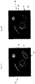
- Figs. 2A and 2B compares the resolution of MRI images obtained at a magnetic field intensity of approximately 7 Tesla with the resolution of MRI images obtained at a magnetic field intensity of approximately 1 Tesla, respectively.
- FIG. 2A shows a scan slice 36 of the small rodent with a tumor 38, taken at a magnetic field intensity of approximately 1 Tesla.
- Fig. 2B shows a scan slice 40 of the rodent with a tumor 39 at a magnetic field intensity of approximately 7 Tesla, at a different slice of the rodent.
- the scan slices 36 and 40 in Figs. 2A and 2B are not the same scan slice.
- the scan slices 36 and 40 are non-coherent.
- the MRI slices 36 and 40 do not include the same content and portion of the rodent.
- pixel-wise registration is not possible.
- the low resolution scan includes a higher SNR level than that of the high resolution scan ( Fig. 2A ).
- the low resolution scan is fused with the high resolution scan of Fig. 2A thereby enhancing the contrast in Fig. 2B .
- the MRI scan in Fig. 2A is a low-resolution image of approximately 300 ⁇ M pixel size and with high contrast between certain tissues.
- Fig. 2A also shows a corresponding grey level scale 42.
- Fig. 2B shows a high resolution scan of approximately 100 ⁇ M resolution with a high SNR and low contrast between the corresponding high contrast tissues of Fig. 2A and a corresponding grey level scale 44.
- the operator wishes to improve the contrast of a tumor area 41 ( Fig. 2B ), relative to the surrounding regions, thereby distinguishing and classifying the tumour area 41.
- the operator decides to enhance the contrast of the tumor area 41 and selects a corresponding area 38 in Fig. 2A .
- the operator and/or processing unit 23 identifies two corresponding regions of interest in Figs. 2A and 2B that are required to be enhanced in Fig. 2B .
- the operator and/or processing unit 23 selects the tumor 38 and a fatty white portion 46 in Fig. 2A .
- the operator and/or processing unit selects corresponding regions 41 and 39 (white region) in Fig. 2B .
- tissue which require enhancing the contrast thereof, is selected.
- the entire tissue region thereof is identified, typically, by a segmentation algorithm based on a previously defined seed voxel, as is known in the art. It is appreciated that the tissue region can also be identified manually by the operator. This identification procedure is performed separately for the images 36, ( Fig. 2A ) and 40 ( Fig. 2B ), since the images 36 and 40 cannot be registered.
- the images 36 and 40 are MRI images of different slices of the target 14. Now a reference region must be segmented in each of the images 3A and 3B.
- a reference region such as a marker reference or a tissue reference, such as muscle portion 47 in Fig. 2A and a muscle portion 48 in Fig. 2B is identified and selected. It is appreciated that the reference tissues 47 and 48 are selected since these reference tissues images appear relatively similar in both spatial extent and in terms of signal strength.
- the segmentation need not be accurate and does not have to include the entire spatial area of "reference object".
- the reference object is used to generate a mean reference signal strength by averaging the signals of its included voxels.
- Ratio_1 mean(segment 38, image 1)/mean(ref segment 47 im 1, Image 1), wherein im 1 is image 36 in Fig. 2A ..
- Ratio_2 mean(segment 41, image 2)/mean(ref segment 48 im 2, Image 2), wherein im 2 is image 46 in Fig. 2A ..
- Ratio_1 is approximately 1.8 and from Fig. 2b , Ratio_2 is approximately 1.
- SF is determined to be approximately 1.8 for the tumor segment.
- Figs. 3A and 3B compare histograms of MRI images of the target taken at a low magnetic field intensity of approximately 1 Tesla and MRI images taken at a high magnetic field intensity of approximately 7 Tesla, respectively, in accordance with a preferred embodiment of the present invention.
- Fig. 3A the pixel populations of the image 36 are shown as a function of the Grey Level (GL) for two different portions of the rodent in the low-field scan.
- GL Grey Level
- FIG. 3A the grey level histograms for a tumor 38 ( Fig. 2A ) and the reference rodent muscle region 47 ( Fig. 2A ) are identified by the respective shaded portions 28 and 30, respectively.
- the y-axis is the proportion of each GL relative to the overall population of pixels in the studied segment (regions 38 and 47).
- Fig. 3A shows that the tumor 38 and muscle regions 47 are clearly distinguishable by their different grey level values.
- the grey level histograms for the tumor 41 and the reference rodent muscle region 48 are identified by the respective shaded portions 32 and 34, respectively.
- Fig. 3B the pixel fractions are compared as a function of the Grey Level (GL) for the tumor 39 ( Fig. 2B ) and the reference muscle region 48 ( Fig. 2B ) of the rodent.
- Fig. 3A the grey level histograms for the tumor 38 and the reference rodent muscle region 47 are identified by the respective shaded portions 28 and 30, respectively.
- Fig. 3B shows that the tumor and muscle regions are not clearly distinguishable by their different grey level values, due to the relatively low relative contrast of the MRI scans obtained at the high magnetic field intensity.
- FIG. 4A and 4B compares the high resolution high-field MRI scan and the enhanced high resolution high-field scan, respectively, in accordance with a preferred embodiment of the present invention.
- Fig. 4A shows the image 50 from the high-field scan and indicates regions of interest 52 and 54 as well as a reference region 56.
- Fig. 4B shows the results of scaling the image 40 ( Fig. 2B ) with the SF's determined from the low field and high field MRI scans.
- a tumor region 62, a white region 64 and a reference region 66 are clearly distinguishable and have a high level of contrast with the remaining portions of the image 60.
- Figs. 4A and 4B shows the contrast enhancement of the two regions, namely, the tumor region and the fat tissue region (white region).
- FIG. 5A shows the cross section image of the cucumber 200 generated at an in-slice pixel size of 0.25 mm (high resolution) and a group of cucumber seeds 204 are clearly distinguishable from a cucumber background 202.
- the image of the cucumber seeds 204 is not clearly distinguishable from the cucumber background 202.
- a group of seeds 206 are not clearly distinguishable from the background 202.
- Fig. 5A shows a group of seeds 201 located on the periphery of the cucumber 200.
- Fig. 5B shows a cross section image of the cucumber 1000 generated at an in-slice pixel size of 0.5 mm (medium resolution) and the group of seeds 1204 is clearly imaged.
- the image of the group of seeds 1206 is clearer. Due to edge effects, the border between the cucumber flesh 1202 and the group of cucumber seeds 1204 is not clearly defined. The group 206 is not clearly distinguishable from the cucumber background 202. Due to the decrease in the resolution, Fig. 5B does not clearly identify a group of seeds located on the periphery of the cucumber 1000.
- Fig. 5C shows a cross section image of the cucumber 2000 generated at an in-slice pixel size of 1 mm (low resolution) and groups of cucumber seeds 2204 and 2206 are not clearly seen and the image is very blurred. Due to the further decrease in the resolution, Fig. 5C does not clearly identify a group of seeds located on the periphery of the cucumber 1000.
- Fig. 5D shows a combined image 3000 of the high resolution (0.25 in-slice pixel size) and medium resolution (0.5 mm in-slice pixel size).
- the group of seeds 3214 is distinguishable from the cucumber background 3212 and the group of seeds 3216 is barely distinguishable from the cucumber background 3212. However, due to noise, the edges of the seeds 3214 and 3216 are not clearly discernible.
- Fig. 5D shows a group of seeds 3218 located on the periphery of the cucumber 3000. To summarize the the resolution in 3000 in Fig. 5D has the full resolution of cucumber 200 in Fig. 5A .
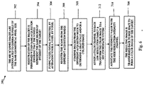
- Fig. 6 presents a flow chart of a typical procedure 300 for fusing multiple sets of images of a given volume of the target 14, into a single enhanced image, in accordance with a preferred embodiment of the present invention.
- the procedure 300 is controlled by the processing unit 23, wherein the images are taken at the same slice of the target 14.
- step 302 the MRI scanned images are interpolated in order to generate voxels of the same geometrical voxel size, as is known in the art.
- step 304 registration of the images acquired from the same acquisition mode is performed.
- the registration procedure ensures that the voxel representations of the images to be fused represent the same region of interest of the target.
- step 306 the registered images are averaged to form a single image for each acquisition mode.
- This image includes a multiplicity of slices.
- step 308 the combined images from the distinct acquisition modes used to image the registered target.
- a typical registration method is "The Lukas-Kanade Optical Flow Method", as is known in art and described in " An Iterative Image Registration Technique with an Application to Stereo Vision", B. D. Lucas and T. Kanade (1981), published in the Proceedings of Imaging Understanding Workshop, pages 121 - 130 . Since the distinct image acquisition modes may have a different appearance, other methods known in the art for registering multi-modality images may be used. These can be based on maximizing mutual information of images patches as is known in the art.
- step 310 the registered MR images of different acquisition modes are fused according to any of the well know fusion methods.
- a method that is suited to variable resolution images acquisitions is outlined:
- the high resolution images are combined to form a single monochrome image as follows:
- the pixel values are combined using some weighting which can be assigned by a variety of methods, such as a principal component analysis.
- the method is known in the art and described in " Principal Component Analysis", by I. T. Jolliffe, Series: Springer Series in Statistics, 2nd ed., Springer, NY, 2002, XXIX, 487 p. 28 illus. ISBN 978-0-387-95442-4 .
- This combined monochrome image controls the brightness and/or intensity of the fused colored image while the low resolution images will control the spectral resolution of the fused image.
- each low-resolution image acquisition mode is assigned a color channel: for example, red, green and blue for three acquisition modes.
- the low resolution image is transformed to the HSV (hue,saturation,value) basis.
- the intensity channel (value) is associated with the high resolution monochrome image and/or combined with the low-resolution intensity channel, for example by the Brovey method, as is known in the art.
- step 320 the resulting image is transformed back to RGB space to form a colored fused final image of the target.
- Figs. 7A - 7C compare in grey and color, the results of combining multi-resolutions images as grey and color images, in accordance with a preferred embodiment of the present invention.
- Fig. 7A shows a high resolution image 500 of a cross section of a cucumber 501 and groups of cucumber seeds 502 and 504.
- Fig. 7A is similar to the high resolution scan shown in Fig. 5A .
- Fig. 7B shows a high resolution image 520 of a cross section of the cucumber 501 and groups of cucumber seeds 502 and 504.
- the high resolution image ( Fig. 5A ), the medium resolution image ( Fig. 5B ) and the low resolution image ( Fig. 5C ) are combined by a IHS method as described in " Application of the IHS Color Transform to the Processing of Multisensor Data and Image Enhancement", (Haydn, R., Dalke, G. W. and Henkel, J.:. Proc. of the International Symposium on Remote Sensing of Arid and Semiarid Lands, Cairo, pp. 599-616, 1982 .),
- the image 520 is clearer than the colored image 510.
- Fig. 7C shows a high resolution image 520 of a cross section of the cucumber 501 and groups of cucumber seeds 502 and 504.
- the high resolution image ( Fig. 5A ), the medium resolution image ( Fig. 5B ) and the low resolution image ( Fig. 5C ) are combined by the Brovey method, as is known in the art (step 314, Fig. 6 ).
- the image 530 clearly distinguishes between the groups of cucumbers 502 and 504 and the groups of cucumbers 502 and 504 are clearly distinguishable from the cucumber background. 501.
Landscapes
- Physics & Mathematics (AREA)
- General Physics & Mathematics (AREA)
- Engineering & Computer Science (AREA)
- High Energy & Nuclear Physics (AREA)
- General Health & Medical Sciences (AREA)
- Condensed Matter Physics & Semiconductors (AREA)
- Health & Medical Sciences (AREA)
- Nuclear Medicine, Radiotherapy & Molecular Imaging (AREA)
- Radiology & Medical Imaging (AREA)
- Signal Processing (AREA)
- Artificial Intelligence (AREA)
- Computer Vision & Pattern Recognition (AREA)
- Theoretical Computer Science (AREA)
- Life Sciences & Earth Sciences (AREA)
- Immunology (AREA)
- Pathology (AREA)
- Biochemistry (AREA)
- Analytical Chemistry (AREA)
- Chemical & Material Sciences (AREA)
- Magnetic Resonance Imaging Apparatus (AREA)
Claims (14)
- Ensemble d'examen par IRM (10) comprenant :un premier dispositif d'examen par IRM (12) configurer pour fonctionner à une première intensité de champ magnétique relativement basse et pour générer une première pluralité d'images IRM d'une cible (14) ;un second dispositif d'examen par IRM (12) configurer pour fonctionner à une seconde intensité de champ magnétique relativement haute et pour générer une seconde pluralité d'images IRM de ladite cible (14) ; etune unité de traitement (23) configurée pour fusionner ladite première pluralité d'images IRM (24) et ladite seconde pluralité d'images IRM (27) pour générer une représentation d'images claire d'au moins une partie de ladite cible (14),les intensités de champ magnétique étant sélectionnées de sorte que la seconde pluralité d'images IRM aient un rapport signal-bruit supérieur mais un contraste inférieur pour des tissus d'intérêt par comparaison avec la première pluralité d'images IRM.
- Ensemble d'examen par IRM (10) selon la revendication 1, dans lequel ladite première intensité de champ magnétique est inférieure à 1,5 teslas et ladite seconde intensité de champ magnétique est supérieure à 5 teslas.
- Ensemble d'examen par IRM (10) selon la revendication 1, comprenant en outre : (a) un sélecteur IRM (22) pour donner des instructions de manière sélective auxdits premier et second dispositifs d'examen par IRM (12) ; et/ou (b) une unité d'affichage d'images (25) pour générer et afficher ladite au moins une partie de ladite cible.
- Ensemble d'examen par IRM (10) selon la revendication 1, dans lequel l'unité de traitement est en outre configurée pour :identifier au moins deux régions d'intérêt dans ladite première pluralité desdites images IRM (24) ;déterminer un facteur d'échelle de niveau monochrome entre lesdites au moins deux régions d'intérêt identifiées ; etfusionner ladite première pluralité d'images IRM (24) et ladite seconde pluralité d'images IRM (27).
- Ensemble d'examen par IRM (10) selon la revendication 4, dans lequel ledit facteur d'échelle de niveau monochrome est sélectionné parmi un niveau de gris, une échelle des rouges une échelle des verts et une échelle des bleus.
- Ensemble d'examen par IRM (10) selon la revendication 4, dans lequel l'unité de traitement est en outre configurée pour mettre à l'échelle chaque image de ladite seconde pluralité d'images (27) avec ledit facteur d'échelle de niveau monochrome.
- Procédé de fusion d'images IRM d'une cible (14), consistant à :fournir un premier dispositif d'examen par IRM (12) configurer pour fonctionner à une première intensité de champ magnétique relativement basse ;fournir un second dispositif d'examen par IRM (12) configurer pour fonctionner à une seconde intensité de champ magnétique relativement haute ;générer une première pluralité d'images IRM (24) de ladite cible par ledit dispositif d'examen par IRM fonctionnant à une première intensité de champ magnétique ;générer une seconde pluralité d'images IRM (27) de ladite cible par ledit dispositif d'examen par IRM fonctionnant à une seconde intensité de champ magnétique ;configurer une unité de traitement (23) pour fusionner ladite première pluralité d'images IRM et ladite seconde pluralité d'images IRM pour générer une représentation d'images claire d'au moins une partie de ladite cible ; etsélectionner les intensités de champ magnétique de sorte que la seconde pluralité d'images IRM aient un rapport signal-bruit supérieur mais un contraste inférieur pour des tissus d'intérêt par comparaison avec la première pluralité d'images IRM.
- Procédé de fusion d'image IRM d'une cible (14) selon la revendication 7, dans lequel ladite première intensité de champ magnétique est inférieure à 1,5 teslas et ladite seconde intensité de champ magnétique est supérieure à 5 teslas.
- Procédé de fusion d'images IRM d'une cible (14) selon la revendication 7, consistant en outre à :donner des instructions de manière sélective auxdits premier et second dispositifs d'examen par IRM (12) ; etgénérer et afficher ladite au moins une partie de ladite cible (14).
- Procédé de fusion d'images IRM d'une cible (14) selon la revendication 7, consistant en outre à :identifier au moins deux régions d'intérêt dans ladite première pluralité desdites images IRM (24) ;déterminer un facteur d'échelle de niveau monochrome entre lesdites au moins deux régions d'intérêt identifiées ; etfusionner ladite première pluralité d'images IRM (24) et ladite seconde pluralité d'images IRM (27).
- Procédé de fusion d'images IRM d'une cible (14) selon la revendication 10, dans lequel ledit facteur d'échelle de niveau monochrome est sélectionné parmi un niveau de gris, une échelle des rouges une échelle des verts et une échelle des bleus.
- Procédé de fusion d'images IRM d'une cible (14) selon la revendication 10, consistant en outre à mettre à l'échelle chaque image de ladite seconde pluralité d'images (27) avec ledit facteur d'échelle de niveau monochrome.
- Procédé de fusion d'images IRM d'une cible (14) selon la revendication 7, dans lequel ladite représentation d'images est une apparence anatomique ou une apparence non anatomique.
- Procédé de fusion d'images IRM d'une cible (14) selon la revendication 7, consistant en outre à sélectionner ladite cible comme une cible provenant d'un groupe constitué de cellules cancéreuses, d'au moins un organe anatomique, d'au moins un organe anatomique cancéreux, d'un produit alimentaire et d'un produit industriel.
Priority Applications (1)
| Application Number | Priority Date | Filing Date | Title |
|---|---|---|---|
| EP22186836.7A EP4116729A1 (fr) | 2010-10-06 | 2011-10-06 | Procédé d'obtenir des images rm fusionnées |
Applications Claiming Priority (2)
| Application Number | Priority Date | Filing Date | Title |
|---|---|---|---|
| US39019610P | 2010-10-06 | 2010-10-06 | |
| PCT/IL2011/000795 WO2012046241A1 (fr) | 2010-10-06 | 2011-10-06 | Procédé permettant d'obtenir des images irm fusionnées à contraste élevé haute résolution |
Related Child Applications (1)
| Application Number | Title | Priority Date | Filing Date |
|---|---|---|---|
| EP22186836.7A Division EP4116729A1 (fr) | 2010-10-06 | 2011-10-06 | Procédé d'obtenir des images rm fusionnées |
Publications (3)
| Publication Number | Publication Date |
|---|---|
| EP2625549A1 EP2625549A1 (fr) | 2013-08-14 |
| EP2625549A4 EP2625549A4 (fr) | 2017-11-15 |
| EP2625549B1 true EP2625549B1 (fr) | 2022-07-27 |
Family
ID=45927290
Family Applications (2)
| Application Number | Title | Priority Date | Filing Date |
|---|---|---|---|
| EP22186836.7A Pending EP4116729A1 (fr) | 2010-10-06 | 2011-10-06 | Procédé d'obtenir des images rm fusionnées |
| EP11830289.2A Active EP2625549B1 (fr) | 2010-10-06 | 2011-10-06 | Procédé permettant d'obtenir des images irm fusionnées à contraste élevé haute résolution |
Family Applications Before (1)
| Application Number | Title | Priority Date | Filing Date |
|---|---|---|---|
| EP22186836.7A Pending EP4116729A1 (fr) | 2010-10-06 | 2011-10-06 | Procédé d'obtenir des images rm fusionnées |
Country Status (4)
| Country | Link |
|---|---|
| US (1) | US9720065B2 (fr) |
| EP (2) | EP4116729A1 (fr) |
| JP (2) | JP6021811B2 (fr) |
| WO (1) | WO2012046241A1 (fr) |
Families Citing this family (19)
| Publication number | Priority date | Publication date | Assignee | Title |
|---|---|---|---|---|
| EP2453250B1 (fr) | 2009-06-30 | 2019-06-12 | Aspect Imaging Ltd. | Cage dans un appareil à résonance magnétique avec système de fixation/atténuation |
| US10191127B2 (en) | 2012-10-31 | 2019-01-29 | Aspect Imaging Ltd. | Magnetic resonance imaging system including a protective cover and a camera |
| US10076266B2 (en) | 2010-07-07 | 2018-09-18 | Aspect Imaging Ltd. | Devices and methods for a neonate incubator, capsule and cart |
| US10794975B2 (en) | 2010-09-16 | 2020-10-06 | Aspect Imaging Ltd. | RF shielding channel in MRI-incubator's closure assembly |
| DE202011051313U1 (de) | 2010-09-16 | 2011-11-23 | Aspect Magnet Technologies Ltd. | Geschlossenes Lebensunterstützungssystem für Frühgeborene |
| US9655542B2 (en) | 2010-09-29 | 2017-05-23 | Aspect Imaging Ltd. | MRI with magnet assembly adapted for convenient scanning of laboratory animals with automated RF tuning unit |
| US10292617B2 (en) | 2010-09-30 | 2019-05-21 | Aspect Imaging Ltd. | Automated tuning and frequency matching with motor movement of RF coil in a magnetic resonance laboratory animal handling system |
| US9720065B2 (en) | 2010-10-06 | 2017-08-01 | Aspect Magnet Technologies Ltd. | Method for providing high resolution, high contrast fused MRI images |
| US20140051975A1 (en) * | 2012-08-15 | 2014-02-20 | Aspect Imaging Ltd. | Multiple heterogeneous imaging systems for clinical and preclinical diagnosis |
| DE202013105212U1 (de) | 2013-11-17 | 2013-12-19 | Aspect Imaging Ltd. | Schließvorrichtung eines MRT-Inkubators |
| US10018692B2 (en) | 2013-11-20 | 2018-07-10 | Aspect Imaging Ltd. | Shutting assembly for closing an entrance of an MRI device |
| WO2015112804A1 (fr) * | 2014-01-23 | 2015-07-30 | The General Hospital Corporation | Systeme et procede pour la generation d'images par imagerie de resonance magnetique (irm) au moyen de structures des images |
| DE202015100024U1 (de) | 2014-01-29 | 2015-03-19 | Aspect Imaging Ltd. | Mittel zum Betreiben einer MRT-Vorrichtung in einer HF-magnetischen Umgebung |
| US11002809B2 (en) | 2014-05-13 | 2021-05-11 | Aspect Imaging Ltd. | Protective and immobilizing sleeves with sensors, and methods for reducing the effect of object movement during MRI scanning |
| US11988730B2 (en) | 2016-08-08 | 2024-05-21 | Aspect Imaging Ltd. | Device, system and method for obtaining a magnetic measurement with permanent magnets |
| US11287497B2 (en) | 2016-08-08 | 2022-03-29 | Aspect Imaging Ltd. | Device, system and method for obtaining a magnetic measurement with permanent magnets |
| US10224135B2 (en) | 2016-08-08 | 2019-03-05 | Aspect Imaging Ltd. | Device, system and method for obtaining a magnetic measurement with permanent magnets |
| US11399732B2 (en) | 2016-09-12 | 2022-08-02 | Aspect Imaging Ltd. | RF coil assembly with a head opening and isolation channel |
| CN109671036B (zh) * | 2018-12-26 | 2023-07-14 | 上海联影医疗科技股份有限公司 | 一种图像校正方法、装置、计算机设备及存储介质 |
Family Cites Families (56)
| Publication number | Priority date | Publication date | Assignee | Title |
|---|---|---|---|---|
| JPH0371048A (ja) * | 1989-08-10 | 1991-03-26 | Sanyo Electric Co Ltd | 青果物の選別装置 |
| US5332968A (en) * | 1992-04-21 | 1994-07-26 | University Of South Florida | Magnetic resonance imaging color composites |
| JPH09140686A (ja) * | 1995-11-21 | 1997-06-03 | Hitachi Medical Corp | 磁気共鳴画像撮像方法 |
| US6278434B1 (en) | 1998-10-07 | 2001-08-21 | Microsoft Corporation | Non-square scaling of image data to be mapped to pixel sub-components |
| DE19962846B4 (de) * | 1999-12-24 | 2008-09-25 | Forschungszentrum Jülich GmbH | Bildgebungsverfahren mit keyhole-Technik |
| CA2482202C (fr) * | 2001-04-13 | 2012-07-03 | Surgi-Vision, Inc. | Systemes et procedes d'interventions guidees par resonance magnetique |
| US6804384B2 (en) | 2001-06-12 | 2004-10-12 | Mclean Hospital Corporation | Color magnetic resonance imaging |
| US6956373B1 (en) | 2002-01-02 | 2005-10-18 | Hugh Keith Brown | Opposed orthogonal fusion system and method for generating color segmented MRI voxel matrices |
| JP2005152114A (ja) * | 2003-11-21 | 2005-06-16 | Ge Medical Systems Global Technology Co Llc | Mri方法およびmri装置 |
| US7483732B2 (en) | 2004-04-15 | 2009-01-27 | Boston Scientific Scimed, Inc. | Magnetic resonance imaging of a medical device and proximate body tissue |
| EP1792265A1 (fr) * | 2004-08-18 | 2007-06-06 | Virtualscopics, LLC. | Utilisation de plusieurs sequences d'impulsions pour la discrimination tridimensionnelle de sous-structures du genou |
| JP2006204551A (ja) * | 2005-01-28 | 2006-08-10 | Kyushu Univ | 生体計測装置及びその方法 |
| US7653264B2 (en) * | 2005-03-04 | 2010-01-26 | The Regents Of The University Of Michigan | Method of determining alignment of images in high dimensional feature space |
| JP5177428B2 (ja) * | 2005-06-09 | 2013-04-03 | アスペクト イメージング リミテッド | 複数試料の同時磁気共鳴画像生成のための携帯型品質/工程管理システム |
| US7400147B2 (en) * | 2005-11-03 | 2008-07-15 | Uri Rapoport | Self-fastening cage surrounding a magnetic resonance device and methods thereof |
| EP1981396A1 (fr) * | 2006-01-30 | 2008-10-22 | Koninklijke Philips Electronics N.V. | Procédés et conception collectique permettant d'améliorer la spécificité de la résonance magnétique mammaire |
| US7744854B2 (en) * | 2006-03-24 | 2010-06-29 | Health Research, Inc. | Method for optimizing cancer therapy by monitoring maturation of tumor associated vasculature by selenium |
| US20100226552A1 (en) * | 2006-03-28 | 2010-09-09 | Koninklijke Philips Electronics N. V. | Identification and visualization of regions of interest in medical imaging |
| EP1933278A1 (fr) * | 2006-12-14 | 2008-06-18 | BrainLAB AG | Visualisation de fusion d'images |
| DE102007030746B4 (de) * | 2007-07-02 | 2010-04-15 | Siemens Ag | Verfahren zum Erstellen eines angiographischen Bildes und Magnet-Resonanz-Gerät |
| JP5369309B2 (ja) * | 2008-04-23 | 2013-12-18 | 独立行政法人日本スポーツ振興センター | 画像処理装置、画像処理プログラム及び磁気共鳴装置 |
| EP2141506B1 (fr) * | 2008-07-01 | 2019-04-03 | The Regents of The University of California | Identification de trajets de fibres par imagerie à résonance magnétique (IRM) |
| US8532740B2 (en) * | 2008-07-08 | 2013-09-10 | Kyushi University | Measurement device and measurement method |
| US20110186049A1 (en) | 2008-08-12 | 2011-08-04 | Aspect Magnet Technologies Ltd. | A system for anesthetizing whilst attuning the temperature of mammals and methods thereof |
| US9061112B2 (en) | 2008-09-10 | 2015-06-23 | Aspect Imaging Ltd | Chamber for housing animals during anaesthetic procedures |
| IL196487A (en) | 2009-01-13 | 2016-03-31 | Aspect Imaging Ltd | Means for buying sharp resolution mri |
| EP2453250B1 (fr) | 2009-06-30 | 2019-06-12 | Aspect Imaging Ltd. | Cage dans un appareil à résonance magnétique avec système de fixation/atténuation |
| US20110234347A1 (en) | 2010-03-24 | 2011-09-29 | Aspect Magnet Technologies Ltd. | Pole piece for permanent magnet mri systems |
| US20130109956A1 (en) | 2010-07-07 | 2013-05-02 | Aspect Imaging Ltd. | Premature neonate life support environmental chamber for use in mri/nmr devices |
| US9562956B2 (en) | 2012-10-31 | 2017-02-07 | Aspect Imaging Ltd. | Rotatable protective cover functioning as a door for MRI system |
| DE202011051313U1 (de) | 2010-09-16 | 2011-11-23 | Aspect Magnet Technologies Ltd. | Geschlossenes Lebensunterstützungssystem für Frühgeborene |
| DE202011051402U1 (de) | 2010-09-27 | 2011-11-25 | Aspect Magnet Technologies Ltd. | Mikrowells mit MRI lesbaren Markierungen |
| DE202011050130U1 (de) | 2010-09-27 | 2011-08-01 | Aspect Magnet Technologies Ltd. | Maske für analysierte Säugetiere |
| DE202011051413U1 (de) | 2010-09-29 | 2012-01-09 | Aspect Magnet Technologies Ltd. | Magnetresonanztomograf mit Magnetenanordnung zum praktischen Scannen von Versuchstieren |
| US8807084B2 (en) | 2010-09-30 | 2014-08-19 | Aspect Imaging Ltd. | MRI device with a plurality of individually controllable entry ports and inserts therefor |
| US9720065B2 (en) * | 2010-10-06 | 2017-08-01 | Aspect Magnet Technologies Ltd. | Method for providing high resolution, high contrast fused MRI images |
| EP2640263A1 (fr) | 2010-11-16 | 2013-09-25 | Aspect Magnet Technologies Ltd. | Système et procédé de génération d'images invasivement hyperpolarisées |
| US20140103927A1 (en) | 2011-02-01 | 2014-04-17 | Uri Rapoport | Low-field magnetic resonance system (lf-mrs) for producing an mri image |
| US20130079624A1 (en) | 2011-09-23 | 2013-03-28 | Uri Rapoport | Graphical user interface for operating an mri |
| US9182461B2 (en) | 2012-06-06 | 2015-11-10 | Aspect Imaging Ltd. | High resolution high contrast MRI for flowing media |
| US20140051974A1 (en) | 2012-08-15 | 2014-02-20 | Aspect Imaging Ltd. | System and method for mri imaging using polarized light |
| US20140050827A1 (en) | 2012-08-15 | 2014-02-20 | Aspect Imaging Ltd. | Non-invasive mri system for analyzing quality of solid food products enveloped by flexible aluminum foil wrapper and methods thereof |
| US20140051975A1 (en) * | 2012-08-15 | 2014-02-20 | Aspect Imaging Ltd. | Multiple heterogeneous imaging systems for clinical and preclinical diagnosis |
| US20140051973A1 (en) | 2012-08-15 | 2014-02-20 | Aspect Imaging Ltd | Mri imaging system for generating a rendered image |
| IL221491A (en) | 2012-08-15 | 2016-06-30 | Aspect Imaging Ltd | A magnetic resonance device integrated with a light field camera |
| US9709652B2 (en) | 2012-10-07 | 2017-07-18 | Aspect Imaging Ltd. | MRI system with means to eliminate object movement whilst acquiring its image |
| US20140128725A1 (en) | 2012-11-08 | 2014-05-08 | Aspect Imaging Ltd. | Neonate's incubator and mri docking-station |
| US9864034B2 (en) | 2012-11-21 | 2018-01-09 | Aspect Imaging Ltd. | Method and system for a universal NMR/MRI console |
| US20140142914A1 (en) | 2012-11-22 | 2014-05-22 | Aspect Imaging Ltd. | Means and methods of multidimensional modeling in vivo spatial image of an mri contrast agent |
| US9551731B2 (en) | 2012-12-02 | 2017-01-24 | Aspect Imaging Ltd. | Gantry for mobilizing an MRI device towards static patients |
| US20140152310A1 (en) | 2012-12-02 | 2014-06-05 | Aspect Imaging Ltd. | Gantry for mobilizing an mri device |
| US20140230850A1 (en) | 2013-02-20 | 2014-08-21 | Aspect Imaging Ltd. | Ramrod for mri and methods thereof |
| US9155490B2 (en) | 2013-03-07 | 2015-10-13 | Aspect Imaging Ltd. | Integrated stethoscope-metal detector device |
| US9535141B2 (en) | 2013-03-13 | 2017-01-03 | Aspect Imaging Ltd. | MRI safety device means and methods thereof |
| US20140300358A1 (en) | 2013-04-08 | 2014-10-09 | Aspect Imaging Ltd. | System and method for real-time noise reduction in mri data acquisition |
| DE202013105901U1 (de) | 2013-09-02 | 2014-02-11 | Aspect Imaging Ltd. | Inkubator mit doppeltverglaster Wand |
-
2011
- 2011-10-06 US US13/877,553 patent/US9720065B2/en active Active
- 2011-10-06 EP EP22186836.7A patent/EP4116729A1/fr active Pending
- 2011-10-06 EP EP11830289.2A patent/EP2625549B1/fr active Active
- 2011-10-06 WO PCT/IL2011/000795 patent/WO2012046241A1/fr active Application Filing
- 2011-10-06 JP JP2013532318A patent/JP6021811B2/ja active Active
-
2016
- 2016-08-17 JP JP2016160012A patent/JP6275787B2/ja active Active
Also Published As
| Publication number | Publication date |
|---|---|
| EP4116729A1 (fr) | 2023-01-11 |
| EP2625549A1 (fr) | 2013-08-14 |
| JP6021811B2 (ja) | 2016-11-09 |
| WO2012046241A9 (fr) | 2013-08-29 |
| JP2013541377A (ja) | 2013-11-14 |
| EP2625549A4 (fr) | 2017-11-15 |
| US9720065B2 (en) | 2017-08-01 |
| US20150077105A1 (en) | 2015-03-19 |
| JP2016214917A (ja) | 2016-12-22 |
| WO2012046241A1 (fr) | 2012-04-12 |
| JP6275787B2 (ja) | 2018-02-07 |
Similar Documents
| Publication | Publication Date | Title |
|---|---|---|
| EP2625549B1 (fr) | Procédé permettant d'obtenir des images irm fusionnées à contraste élevé haute résolution | |
| US6956373B1 (en) | Opposed orthogonal fusion system and method for generating color segmented MRI voxel matrices | |
| Fracasso et al. | Lines of Baillarger in vivo and ex vivo: Myelin contrast across lamina at 7 T MRI and histology | |
| Nyúl et al. | New variants of a method of MRI scale standardization | |
| US8724875B2 (en) | Attenuation correction for PET or SPECT nuclear imaging systems using magnetic resonance spectroscopic image data | |
| JP5562598B2 (ja) | 画像表示装置、画像表示方法および磁気共鳴イメージング装置 | |
| US9295406B2 (en) | Automatic or semi-automatic whole body MR scanning system | |
| JP6979151B2 (ja) | 磁気共鳴イメージング装置及び磁気共鳴画像処理方法 | |
| US7136516B2 (en) | Method and system for segmenting magnetic resonance images | |
| WO2003098253A1 (fr) | Tractographie en temps reel | |
| US7818042B2 (en) | Method and apparatus for uniquely identifying tissue pathology | |
| JP2007503904A (ja) | 高磁場磁気共鳴撮像のための適応的画像均一性補正 | |
| Gulban et al. | Mesoscopic in vivo human T2* dataset acquired using quantitative MRI at 7 Tesla | |
| US9952301B2 (en) | System and method for selecting and modifying a hanging protocol for displaying MRI information | |
| Butler et al. | Application of polymer sensitive MRI sequence to localization of EEG electrodes | |
| JP2020049237A (ja) | 微細構造解析データのデータ品質を評価し向上させる方法 | |
| US20050203379A1 (en) | Method and apparatus for MR image evaluation by mapping perfusion-weighted and diffusion-weighted MR images | |
| Fracasso et al. | Myelin contrast across lamina at 7T, ex-vivo and in-vivo dataset | |
| CN110022766A (zh) | 组织的弥散椭球映射 | |
| Ogawa et al. | Evaluation of thin-slice coronal single-shot turbo spin-echo diffusion-weighted imaging of the hand: A comparison with conventional echo-planar diffusion-weighted imaging | |
| Chandra et al. | Local contrast‐enhanced MR images via high dynamic range processing | |
| Durairaj et al. | Integration of color and boundary information for improved region of interest identification in electron magnetic resonance images | |
| JP5439078B2 (ja) | 磁気共鳴イメージング装置及びその作動方法 | |
| Nyul et al. | Protocol-independent brain MRI segmentation method | |
| Eyal et al. | 3-D tracking of the mammary ductal tree using diffusion tensor MR imaging |
Legal Events
| Date | Code | Title | Description |
|---|---|---|---|
| PUAI | Public reference made under article 153(3) epc to a published international application that has entered the european phase |
Free format text: ORIGINAL CODE: 0009012 |
|
| 17P | Request for examination filed |
Effective date: 20130426 |
|
| AK | Designated contracting states |
Kind code of ref document: A1 Designated state(s): AL AT BE BG CH CY CZ DE DK EE ES FI FR GB GR HR HU IE IS IT LI LT LU LV MC MK MT NL NO PL PT RO RS SE SI SK SM TR |
|
| DAX | Request for extension of the european patent (deleted) | ||
| REG | Reference to a national code |
Ref country code: HK Ref legal event code: DE Ref document number: 1188296 Country of ref document: HK |
|
| RAP1 | Party data changed (applicant data changed or rights of an application transferred) |
Owner name: ASPECT IMAGING LTD. |
|
| REG | Reference to a national code |
Ref country code: DE Ref legal event code: R079 Ref document number: 602011073137 Country of ref document: DE Free format text: PREVIOUS MAIN CLASS: G01V0003000000 Ipc: G01R0033560000 |
|
| RIC1 | Information provided on ipc code assigned before grant |
Ipc: G01V 3/00 20060101ALI20171002BHEP Ipc: G01R 33/56 20060101AFI20171002BHEP Ipc: A61B 6/00 20060101ALI20171002BHEP Ipc: G06T 7/00 20170101ALI20171002BHEP Ipc: G01N 24/08 20060101ALI20171002BHEP Ipc: G06T 5/50 20060101ALI20171002BHEP |
|
| RA4 | Supplementary search report drawn up and despatched (corrected) |
Effective date: 20171013 |
|
| REG | Reference to a national code |
Ref country code: HK Ref legal event code: WD Ref document number: 1188296 Country of ref document: HK |
|
| STAA | Information on the status of an ep patent application or granted ep patent |
Free format text: STATUS: EXAMINATION IS IN PROGRESS |
|
| 17Q | First examination report despatched |
Effective date: 20200528 |
|
| STAA | Information on the status of an ep patent application or granted ep patent |
Free format text: STATUS: EXAMINATION IS IN PROGRESS |
|
| GRAP | Despatch of communication of intention to grant a patent |
Free format text: ORIGINAL CODE: EPIDOSNIGR1 |
|
| STAA | Information on the status of an ep patent application or granted ep patent |
Free format text: STATUS: GRANT OF PATENT IS INTENDED |
|
| INTG | Intention to grant announced |
Effective date: 20210906 |
|
| GRAJ | Information related to disapproval of communication of intention to grant by the applicant or resumption of examination proceedings by the epo deleted |
Free format text: ORIGINAL CODE: EPIDOSDIGR1 |
|
| STAA | Information on the status of an ep patent application or granted ep patent |
Free format text: STATUS: EXAMINATION IS IN PROGRESS |
|
| GRAP | Despatch of communication of intention to grant a patent |
Free format text: ORIGINAL CODE: EPIDOSNIGR1 |
|
| STAA | Information on the status of an ep patent application or granted ep patent |
Free format text: STATUS: GRANT OF PATENT IS INTENDED |
|
| INTC | Intention to grant announced (deleted) | ||
| RAP3 | Party data changed (applicant data changed or rights of an application transferred) |
Owner name: ASPECT IMAGING LTD. |
|
| INTG | Intention to grant announced |
Effective date: 20220214 |
|
| GRAS | Grant fee paid |
Free format text: ORIGINAL CODE: EPIDOSNIGR3 |
|
| GRAA | (expected) grant |
Free format text: ORIGINAL CODE: 0009210 |
|
| STAA | Information on the status of an ep patent application or granted ep patent |
Free format text: STATUS: THE PATENT HAS BEEN GRANTED |
|
| AK | Designated contracting states |
Kind code of ref document: B1 Designated state(s): AL AT BE BG CH CY CZ DE DK EE ES FI FR GB GR HR HU IE IS IT LI LT LU LV MC MK MT NL NO PL PT RO RS SE SI SK SM TR |
|
| REG | Reference to a national code |
Ref country code: GB Ref legal event code: FG4D |
|
| REG | Reference to a national code |
Ref country code: CH Ref legal event code: EP |
|
| REG | Reference to a national code |
Ref country code: AT Ref legal event code: REF Ref document number: 1507418 Country of ref document: AT Kind code of ref document: T Effective date: 20220815 |
|
| REG | Reference to a national code |
Ref country code: DE Ref legal event code: R096 Ref document number: 602011073137 Country of ref document: DE |
|
| REG | Reference to a national code |
Ref country code: IE Ref legal event code: FG4D |
|
| REG | Reference to a national code |
Ref country code: NL Ref legal event code: FP |
|
| REG | Reference to a national code |
Ref country code: LT Ref legal event code: MG9D |
|
| REG | Reference to a national code |
Ref country code: DE Ref legal event code: R082 Ref document number: 602011073137 Country of ref document: DE Representative=s name: FORRESTERS IP LLP, DE Ref country code: DE Ref legal event code: R082 Ref document number: 602011073137 Country of ref document: DE Representative=s name: KUEHR, VERA, DIPL.-BIOL., DE |
|
| PG25 | Lapsed in a contracting state [announced via postgrant information from national office to epo] |
Ref country code: SE Free format text: LAPSE BECAUSE OF FAILURE TO SUBMIT A TRANSLATION OF THE DESCRIPTION OR TO PAY THE FEE WITHIN THE PRESCRIBED TIME-LIMIT Effective date: 20220727 Ref country code: RS Free format text: LAPSE BECAUSE OF FAILURE TO SUBMIT A TRANSLATION OF THE DESCRIPTION OR TO PAY THE FEE WITHIN THE PRESCRIBED TIME-LIMIT Effective date: 20220727 Ref country code: PT Free format text: LAPSE BECAUSE OF FAILURE TO SUBMIT A TRANSLATION OF THE DESCRIPTION OR TO PAY THE FEE WITHIN THE PRESCRIBED TIME-LIMIT Effective date: 20221128 Ref country code: NO Free format text: LAPSE BECAUSE OF FAILURE TO SUBMIT A TRANSLATION OF THE DESCRIPTION OR TO PAY THE FEE WITHIN THE PRESCRIBED TIME-LIMIT Effective date: 20221027 Ref country code: LV Free format text: LAPSE BECAUSE OF FAILURE TO SUBMIT A TRANSLATION OF THE DESCRIPTION OR TO PAY THE FEE WITHIN THE PRESCRIBED TIME-LIMIT Effective date: 20220727 Ref country code: LT Free format text: LAPSE BECAUSE OF FAILURE TO SUBMIT A TRANSLATION OF THE DESCRIPTION OR TO PAY THE FEE WITHIN THE PRESCRIBED TIME-LIMIT Effective date: 20220727 Ref country code: FI Free format text: LAPSE BECAUSE OF FAILURE TO SUBMIT A TRANSLATION OF THE DESCRIPTION OR TO PAY THE FEE WITHIN THE PRESCRIBED TIME-LIMIT Effective date: 20220727 Ref country code: ES Free format text: LAPSE BECAUSE OF FAILURE TO SUBMIT A TRANSLATION OF THE DESCRIPTION OR TO PAY THE FEE WITHIN THE PRESCRIBED TIME-LIMIT Effective date: 20220727 |
|
| REG | Reference to a national code |
Ref country code: AT Ref legal event code: MK05 Ref document number: 1507418 Country of ref document: AT Kind code of ref document: T Effective date: 20220727 |
|
| PG25 | Lapsed in a contracting state [announced via postgrant information from national office to epo] |
Ref country code: PL Free format text: LAPSE BECAUSE OF FAILURE TO SUBMIT A TRANSLATION OF THE DESCRIPTION OR TO PAY THE FEE WITHIN THE PRESCRIBED TIME-LIMIT Effective date: 20220727 Ref country code: IS Free format text: LAPSE BECAUSE OF FAILURE TO SUBMIT A TRANSLATION OF THE DESCRIPTION OR TO PAY THE FEE WITHIN THE PRESCRIBED TIME-LIMIT Effective date: 20221127 Ref country code: HR Free format text: LAPSE BECAUSE OF FAILURE TO SUBMIT A TRANSLATION OF THE DESCRIPTION OR TO PAY THE FEE WITHIN THE PRESCRIBED TIME-LIMIT Effective date: 20220727 Ref country code: GR Free format text: LAPSE BECAUSE OF FAILURE TO SUBMIT A TRANSLATION OF THE DESCRIPTION OR TO PAY THE FEE WITHIN THE PRESCRIBED TIME-LIMIT Effective date: 20221028 |
|
| PG25 | Lapsed in a contracting state [announced via postgrant information from national office to epo] |
Ref country code: SM Free format text: LAPSE BECAUSE OF FAILURE TO SUBMIT A TRANSLATION OF THE DESCRIPTION OR TO PAY THE FEE WITHIN THE PRESCRIBED TIME-LIMIT Effective date: 20220727 Ref country code: RO Free format text: LAPSE BECAUSE OF FAILURE TO SUBMIT A TRANSLATION OF THE DESCRIPTION OR TO PAY THE FEE WITHIN THE PRESCRIBED TIME-LIMIT Effective date: 20220727 Ref country code: DK Free format text: LAPSE BECAUSE OF FAILURE TO SUBMIT A TRANSLATION OF THE DESCRIPTION OR TO PAY THE FEE WITHIN THE PRESCRIBED TIME-LIMIT Effective date: 20220727 Ref country code: CZ Free format text: LAPSE BECAUSE OF FAILURE TO SUBMIT A TRANSLATION OF THE DESCRIPTION OR TO PAY THE FEE WITHIN THE PRESCRIBED TIME-LIMIT Effective date: 20220727 Ref country code: AT Free format text: LAPSE BECAUSE OF FAILURE TO SUBMIT A TRANSLATION OF THE DESCRIPTION OR TO PAY THE FEE WITHIN THE PRESCRIBED TIME-LIMIT Effective date: 20220727 |
|
| REG | Reference to a national code |
Ref country code: DE Ref legal event code: R097 Ref document number: 602011073137 Country of ref document: DE |
|
| PG25 | Lapsed in a contracting state [announced via postgrant information from national office to epo] |
Ref country code: SK Free format text: LAPSE BECAUSE OF FAILURE TO SUBMIT A TRANSLATION OF THE DESCRIPTION OR TO PAY THE FEE WITHIN THE PRESCRIBED TIME-LIMIT Effective date: 20220727 Ref country code: MC Free format text: LAPSE BECAUSE OF FAILURE TO SUBMIT A TRANSLATION OF THE DESCRIPTION OR TO PAY THE FEE WITHIN THE PRESCRIBED TIME-LIMIT Effective date: 20220727 Ref country code: EE Free format text: LAPSE BECAUSE OF FAILURE TO SUBMIT A TRANSLATION OF THE DESCRIPTION OR TO PAY THE FEE WITHIN THE PRESCRIBED TIME-LIMIT Effective date: 20220727 |
|
| REG | Reference to a national code |
Ref country code: CH Ref legal event code: PL |
|
| PLBE | No opposition filed within time limit |
Free format text: ORIGINAL CODE: 0009261 |
|
| STAA | Information on the status of an ep patent application or granted ep patent |
Free format text: STATUS: NO OPPOSITION FILED WITHIN TIME LIMIT |
|
| REG | Reference to a national code |
Ref country code: BE Ref legal event code: MM Effective date: 20221031 |
|
| PG25 | Lapsed in a contracting state [announced via postgrant information from national office to epo] |
Ref country code: LU Free format text: LAPSE BECAUSE OF NON-PAYMENT OF DUE FEES Effective date: 20221006 Ref country code: AL Free format text: LAPSE BECAUSE OF FAILURE TO SUBMIT A TRANSLATION OF THE DESCRIPTION OR TO PAY THE FEE WITHIN THE PRESCRIBED TIME-LIMIT Effective date: 20220727 |
|
| 26N | No opposition filed |
Effective date: 20230502 |
|
| P01 | Opt-out of the competence of the unified patent court (upc) registered |
Effective date: 20230526 |
|
| PG25 | Lapsed in a contracting state [announced via postgrant information from national office to epo] |
Ref country code: LI Free format text: LAPSE BECAUSE OF NON-PAYMENT OF DUE FEES Effective date: 20221031 Ref country code: CH Free format text: LAPSE BECAUSE OF NON-PAYMENT OF DUE FEES Effective date: 20221031 |
|
| PG25 | Lapsed in a contracting state [announced via postgrant information from national office to epo] |
Ref country code: SI Free format text: LAPSE BECAUSE OF FAILURE TO SUBMIT A TRANSLATION OF THE DESCRIPTION OR TO PAY THE FEE WITHIN THE PRESCRIBED TIME-LIMIT Effective date: 20220727 |
|
| PG25 | Lapsed in a contracting state [announced via postgrant information from national office to epo] |
Ref country code: BE Free format text: LAPSE BECAUSE OF NON-PAYMENT OF DUE FEES Effective date: 20221031 |
|
| REG | Reference to a national code |
Ref country code: DE Ref legal event code: R082 Ref document number: 602011073137 Country of ref document: DE Representative=s name: FORRESTERS IP LLP, DE |
|
| PG25 | Lapsed in a contracting state [announced via postgrant information from national office to epo] |
Ref country code: IE Free format text: LAPSE BECAUSE OF NON-PAYMENT OF DUE FEES Effective date: 20221006 |
|
| PGFP | Annual fee paid to national office [announced via postgrant information from national office to epo] |
Ref country code: NL Payment date: 20231019 Year of fee payment: 13 |
|
| PGFP | Annual fee paid to national office [announced via postgrant information from national office to epo] |
Ref country code: GB Payment date: 20231020 Year of fee payment: 13 |
|
| PGFP | Annual fee paid to national office [announced via postgrant information from national office to epo] |
Ref country code: FR Payment date: 20231025 Year of fee payment: 13 Ref country code: DE Payment date: 20231020 Year of fee payment: 13 |
|
| PG25 | Lapsed in a contracting state [announced via postgrant information from national office to epo] |
Ref country code: HU Free format text: LAPSE BECAUSE OF FAILURE TO SUBMIT A TRANSLATION OF THE DESCRIPTION OR TO PAY THE FEE WITHIN THE PRESCRIBED TIME-LIMIT; INVALID AB INITIO Effective date: 20111006 |
|
| PG25 | Lapsed in a contracting state [announced via postgrant information from national office to epo] |
Ref country code: CY Free format text: LAPSE BECAUSE OF FAILURE TO SUBMIT A TRANSLATION OF THE DESCRIPTION OR TO PAY THE FEE WITHIN THE PRESCRIBED TIME-LIMIT Effective date: 20220727 |