EP2625247B1 - Mn-activated phosphors - Google Patents
Mn-activated phosphors Download PDFInfo
- Publication number
- EP2625247B1 EP2625247B1 EP11761009.7A EP11761009A EP2625247B1 EP 2625247 B1 EP2625247 B1 EP 2625247B1 EP 11761009 A EP11761009 A EP 11761009A EP 2625247 B1 EP2625247 B1 EP 2625247B1
- Authority
- EP
- European Patent Office
- Prior art keywords
- phosphor
- range
- stands
- phosphors
- value
- Prior art date
- Legal status (The legal status is an assumption and is not a legal conclusion. Google has not performed a legal analysis and makes no representation as to the accuracy of the status listed.)
- Not-in-force
Links
Images


Classifications
-
- C—CHEMISTRY; METALLURGY
- C09—DYES; PAINTS; POLISHES; NATURAL RESINS; ADHESIVES; COMPOSITIONS NOT OTHERWISE PROVIDED FOR; APPLICATIONS OF MATERIALS NOT OTHERWISE PROVIDED FOR
- C09K—MATERIALS FOR MISCELLANEOUS APPLICATIONS, NOT PROVIDED FOR ELSEWHERE
- C09K11/00—Luminescent, e.g. electroluminescent, chemiluminescent materials
- C09K11/08—Luminescent, e.g. electroluminescent, chemiluminescent materials containing inorganic luminescent materials
- C09K11/77—Luminescent, e.g. electroluminescent, chemiluminescent materials containing inorganic luminescent materials containing rare earth metals
- C09K11/7766—Luminescent, e.g. electroluminescent, chemiluminescent materials containing inorganic luminescent materials containing rare earth metals containing two or more rare earth metals
- C09K11/7767—Chalcogenides
- C09K11/7769—Oxides
-
- C—CHEMISTRY; METALLURGY
- C09—DYES; PAINTS; POLISHES; NATURAL RESINS; ADHESIVES; COMPOSITIONS NOT OTHERWISE PROVIDED FOR; APPLICATIONS OF MATERIALS NOT OTHERWISE PROVIDED FOR
- C09K—MATERIALS FOR MISCELLANEOUS APPLICATIONS, NOT PROVIDED FOR ELSEWHERE
- C09K11/00—Luminescent, e.g. electroluminescent, chemiluminescent materials
- C09K11/08—Luminescent, e.g. electroluminescent, chemiluminescent materials containing inorganic luminescent materials
- C09K11/77—Luminescent, e.g. electroluminescent, chemiluminescent materials containing inorganic luminescent materials containing rare earth metals
-
- C—CHEMISTRY; METALLURGY
- C09—DYES; PAINTS; POLISHES; NATURAL RESINS; ADHESIVES; COMPOSITIONS NOT OTHERWISE PROVIDED FOR; APPLICATIONS OF MATERIALS NOT OTHERWISE PROVIDED FOR
- C09K—MATERIALS FOR MISCELLANEOUS APPLICATIONS, NOT PROVIDED FOR ELSEWHERE
- C09K11/00—Luminescent, e.g. electroluminescent, chemiluminescent materials
- C09K11/08—Luminescent, e.g. electroluminescent, chemiluminescent materials containing inorganic luminescent materials
- C09K11/59—Luminescent, e.g. electroluminescent, chemiluminescent materials containing inorganic luminescent materials containing silicon
-
- C—CHEMISTRY; METALLURGY
- C09—DYES; PAINTS; POLISHES; NATURAL RESINS; ADHESIVES; COMPOSITIONS NOT OTHERWISE PROVIDED FOR; APPLICATIONS OF MATERIALS NOT OTHERWISE PROVIDED FOR
- C09K—MATERIALS FOR MISCELLANEOUS APPLICATIONS, NOT PROVIDED FOR ELSEWHERE
- C09K11/00—Luminescent, e.g. electroluminescent, chemiluminescent materials
- C09K11/08—Luminescent, e.g. electroluminescent, chemiluminescent materials containing inorganic luminescent materials
- C09K11/70—Luminescent, e.g. electroluminescent, chemiluminescent materials containing inorganic luminescent materials containing phosphorus
- C09K11/71—Luminescent, e.g. electroluminescent, chemiluminescent materials containing inorganic luminescent materials containing phosphorus also containing alkaline earth metals
-
- C—CHEMISTRY; METALLURGY
- C09—DYES; PAINTS; POLISHES; NATURAL RESINS; ADHESIVES; COMPOSITIONS NOT OTHERWISE PROVIDED FOR; APPLICATIONS OF MATERIALS NOT OTHERWISE PROVIDED FOR
- C09K—MATERIALS FOR MISCELLANEOUS APPLICATIONS, NOT PROVIDED FOR ELSEWHERE
- C09K11/00—Luminescent, e.g. electroluminescent, chemiluminescent materials
- C09K11/08—Luminescent, e.g. electroluminescent, chemiluminescent materials containing inorganic luminescent materials
- C09K11/77—Luminescent, e.g. electroluminescent, chemiluminescent materials containing inorganic luminescent materials containing rare earth metals
- C09K11/7701—Chalogenides
- C09K11/7703—Chalogenides with alkaline earth metals
-
- C—CHEMISTRY; METALLURGY
- C09—DYES; PAINTS; POLISHES; NATURAL RESINS; ADHESIVES; COMPOSITIONS NOT OTHERWISE PROVIDED FOR; APPLICATIONS OF MATERIALS NOT OTHERWISE PROVIDED FOR
- C09K—MATERIALS FOR MISCELLANEOUS APPLICATIONS, NOT PROVIDED FOR ELSEWHERE
- C09K11/00—Luminescent, e.g. electroluminescent, chemiluminescent materials
- C09K11/08—Luminescent, e.g. electroluminescent, chemiluminescent materials containing inorganic luminescent materials
- C09K11/77—Luminescent, e.g. electroluminescent, chemiluminescent materials containing inorganic luminescent materials containing rare earth metals
- C09K11/7706—Aluminates
-
- C—CHEMISTRY; METALLURGY
- C09—DYES; PAINTS; POLISHES; NATURAL RESINS; ADHESIVES; COMPOSITIONS NOT OTHERWISE PROVIDED FOR; APPLICATIONS OF MATERIALS NOT OTHERWISE PROVIDED FOR
- C09K—MATERIALS FOR MISCELLANEOUS APPLICATIONS, NOT PROVIDED FOR ELSEWHERE
- C09K11/00—Luminescent, e.g. electroluminescent, chemiluminescent materials
- C09K11/08—Luminescent, e.g. electroluminescent, chemiluminescent materials containing inorganic luminescent materials
- C09K11/77—Luminescent, e.g. electroluminescent, chemiluminescent materials containing inorganic luminescent materials containing rare earth metals
- C09K11/7766—Luminescent, e.g. electroluminescent, chemiluminescent materials containing inorganic luminescent materials containing rare earth metals containing two or more rare earth metals
- C09K11/7774—Aluminates
-
- H—ELECTRICITY
- H01—ELECTRIC ELEMENTS
- H01L—SEMICONDUCTOR DEVICES NOT COVERED BY CLASS H10
- H01L33/00—Semiconductor devices with at least one potential-jump barrier or surface barrier specially adapted for light emission; Processes or apparatus specially adapted for the manufacture or treatment thereof or of parts thereof; Details thereof
- H01L33/48—Semiconductor devices with at least one potential-jump barrier or surface barrier specially adapted for light emission; Processes or apparatus specially adapted for the manufacture or treatment thereof or of parts thereof; Details thereof characterised by the semiconductor body packages
- H01L33/50—Wavelength conversion elements
- H01L33/501—Wavelength conversion elements characterised by the materials, e.g. binder
- H01L33/502—Wavelength conversion materials
-
- H—ELECTRICITY
- H05—ELECTRIC TECHNIQUES NOT OTHERWISE PROVIDED FOR
- H05B—ELECTRIC HEATING; ELECTRIC LIGHT SOURCES NOT OTHERWISE PROVIDED FOR; CIRCUIT ARRANGEMENTS FOR ELECTRIC LIGHT SOURCES, IN GENERAL
- H05B33/00—Electroluminescent light sources
- H05B33/12—Light sources with substantially two-dimensional radiating surfaces
- H05B33/14—Light sources with substantially two-dimensional radiating surfaces characterised by the chemical or physical composition or the arrangement of the electroluminescent material, or by the simultaneous addition of the electroluminescent material in or onto the light source
Definitions
- the invention relates to Mn 4+ -activated phosphors, processes for the preparation of these compounds and their use as conversion phosphors or in illuminants.
- Luminescent materials are used in fluorescent light sources, emissive screens and as scintillator crystals for the conversion of non-visible radiation or high energy particles into visible light.
- a class of materials that has become widely used for this task are the Ce 3+ doped garnets, in particular Y 3 Al 5 O 12 : Ce (YAG) and (Gd 1-x Y x ) 3 (Al 1-y Ga y ) 5 O 12: Ce (YAGaG: Ce), said other dopants such as Lu 3+ or Tb 3+ were used for the optimization of the spectrum.
- white LEDs were realized by the partial conversion of the blue light with YAG: Ce or YAGaG: Ce, because the yellow-orange emission color of these phosphors is complementary to the blue emission color of the LEDs, and thus additive white light can be obtained.
- all commercially available white LEDs contain a blue-emitting InGaN chip covered with a layer of YAG: Ce or YAGaG: Ce.
- Significant disadvantages of this approach is, on the one hand, the dependence of the emission color on the viewing angle, which is a consequence of the non-homogeneous coating of the chip.
- the current primary goal for extending the product range and improving the color rendering of white LEDs is the realization of trichromatic LEDs.
- green or yellow and red-emitting phosphors with high absorption in the blue spectral range, with high quantum efficiency and a high lumen equivalent must be provided.
- red-emitting phosphors such as (Ca, Sr) S: Eu, (Ca, Sr, Ba) 2 Si 5 N 8 : Eu and (Ca, Sr) AlSiN 3 : Eu or mixtures of these luminophores were already proposed in a variety of patent applications.
- a disadvantage of the previously used red emitting phosphors is their relatively low stability, which is due in part to the susceptibility to hydrolysis of the sulfidic or nitridic host lattices and partly to the redox lability of the Eu 2+ activator.
- the lumen equivalent of 200-270 lm / W is not as high as that of Eu 3+ phosphors with 280-360 lm / W due to the broad emission band. Therefore, the search for efficient and stable red-emitting phosphors for LEDs with high lumen equivalent continues unabated.
- garnet phosphors of the rare earth metals of the general type (Gd, Tb, La, Lu, Y) 3 (Al, Ga) 5 O 12 : (Ce, Eu, Nd, Er, Cr, Mn) are known.
- Garnet phosphors according to the present invention containing both manganese and calcium are not disclosed.
- garnet phosphors of the rare earth metals of the general type (Y, Gd, Lu, Tb) 3 (Al, Ga) 5 O 12 : Ce are known.
- Garnet phosphors according to the present invention containing both manganese and calcium are not disclosed.
- Object of the present invention was to develop lutetium-containing garnet phosphors, which have a red luminescence and Particularly suitable for use in high-performance pcLEDs for producing warm white light.
- Mn 4+ -activated lutetium-containing garnet phosphors fulfill the abovementioned object.
- the incorporation of tetravalent manganese in the lattice site of the trivalent aluminum must be compensated by the incorporation of a divalent ion, such as Ca 2+ or Sr 2+ on the Lu 3+ place.
- x is a value in the range 0 to 2.0 and particularly preferably in the range 0.10 to 0.90.
- y is a value from the range 0.10 to 0.45, particularly preferably from the range 0.20 to 0.40.
- LED quality is described using common parameters, such as the Color Rendering Index or the color point in CIE x and CIE y coordinates.
- the Color Rendering Index is a unitary photometric quantity known to those skilled in the art that compares the color fidelity of an artificial light source to that of sunlight or filament light sources (the latter two have a CRI of 100).
- CIE x and CIE y stand for the coordinates in the CIE standard color diagram familiar to the person skilled in the art (here standard observer 1931), with which the color of a light source is described. All the variables listed above are calculated from emission spectra of the light source according to methods familiar to the person skilled in the art.
- red light such light whose intensity maximum is between 600 and 680 nm wavelength.
- the reaction is usually carried out at a temperature above 800 ° C.
- the calcination may also be carried out under reducing conditions (e.g., with carbon monoxide, forming gas or hydrogen or oxygen depleted atmosphere).
- An inorganic or organic substance is a substance from the group of ammonium halides, alkaline earth fluorides such as calcium, strontium or barium fluoride, (earth) alkali metal borates, boric acid, (earth) alkali metal carbonates or ammonium bicarbonate, Citric acid, alcoholates and oxalates and / or silicic acid esters such as TEOS used.
- alkaline earth fluorides such as calcium, strontium or barium fluoride
- boric acid earth alkali metal carbonates or ammonium bicarbonate
- Citric acid e.g., citric acid and an oxalate are added.
- the oxalate may also be added in step a).
- the phosphors according to the invention can be prepared either by a conventional solid-state diffusion method (starting from the oxides, nitrates, carbonates or halides of the corresponding alkaline earth metals, semimetals, metals or rare earths) or wet-chemically from inorganic and / or organic metal and / or rare earth salts by means of sol Gel process, coprecipitation and / or drying process.
- a conventional solid-state diffusion method starting from the oxides, nitrates, carbonates or halides of the corresponding alkaline earth metals, semimetals, metals or rare earths
- wet-chemically from inorganic and / or organic metal and / or rare earth salts by means of sol Gel process, coprecipitation and / or drying process.
- wet-chemical processes particularly preferably wet-chemical by the addition of citric acid.
- chloride solutions of the corresponding phosphor educts are admixed with a TEOS / NH 4 HCO 3 solution, whereby the phosphor precursor is formed, which is subsequently converted into the phosphor by a one-stage or multistage thermal treatment.
- Spray pyrolysis belongs to the aerosol processes which are characterized by spraying solutions, suspensions or dispersions into a reaction chamber (reactor) which has been heated in different ways, as well as the formation and separation of solid particles.
- spray pyrolysis as the high-temperature process is characterized by the thermal decomposition of the educts used (eg salts) and the formation of new substances (eg oxides, mixed oxides ) instead of.
- the orange-red emitting phosphors of the present invention may also be mixed with green emitting phosphors, making such blends highly suitable for general lighting applications (e.g., warm white LEDs) and LCD backlighting.
- a further embodiment of the present invention is therefore a mixture comprising at least one compound of the formula I and at least one green-emitting phosphor, which is preferably selected from Ce-doped garnets, preferably LuAG: Ce, (Sr, Ca) Si 2 N 2 O 2 : Eu, (Sr, Ba) 2 SiO 4 : Eu, or CaSc 2 O 4 : Ce, Na.
- Ce-doped garnets preferably LuAG: Ce, (Sr, Ca) Si 2 N 2 O 2 : Eu, (Sr, Ba) 2 SiO 4 : Eu, or CaSc 2 O 4 : Ce, Na.
- the compound (or phosphor) according to formula I and the at least one green emitting phosphor are usually present in a weight ratio of 20: 1 to 1: 1. It is preferred according to the invention for the at least one phosphor of the formula I and the at least one green-emitting phosphor to be present in a weight ratio of 10: 1 to 3: 1 and particularly preferably 6: 1 to 4: 1.
- the particle size of the phosphors according to the invention is usually between 50 nm and 30 .mu.m, preferably between 1 .mu.m and 20 .mu.m.
- the phosphors in particle form have a closed surface coating consisting of SiO 2 , TiO 2 , Al 2 O 3 , ZnO, ZrO 2 and / or Y 2 O 3 or mixed oxides thereof.
- This surface coating has the advantage that by a suitable Grading the refractive indices of the coating materials, an adjustment of the refractive index can be achieved with the environment. In this case, the scattering of the light at the surface of the phosphor is reduced and a larger proportion of the light can penetrate into the phosphor where it is absorbed and converted.
- the refractive index matched surface coating allows more light to be coupled out of the phosphor because the total internal reflection is reduced.
- a closed layer is advantageous if the phosphor has to be encapsulated. This may be necessary to counter sensitivity of the phosphor or parts thereof to diffusing water or other materials in the immediate environment. Another reason for the encapsulation with a closed shell is a thermal decoupling of the actual phosphor from the heat that arises in the chip. This heat leads to a reduction in the fluorescent light output of the phosphor and may also affect the color of the fluorescent light. Finally, it is possible by such a coating to increase the efficiency of the phosphor by preventing lattice vibrations arising in the phosphor from propagating to the environment.
- the phosphors have a porous surface coating consisting of SiO 2 , TiO 2 , Al 2 O 3 , ZnO, ZrO 2 and / or Y 2 O 3 or mixed oxides thereof or of the phosphor composition.
- These porous coatings offer the possibility of further reducing the refractive index of a single layer.
- the preparation of such porous coatings can be accomplished by three conventional methods as described in US Pat WO 03/027015 which is fully incorporated by reference into the context of the present application: the etching of glass (eg Soda lime glasses (see US 4,019,884 )), the application of a porous layer and the combination of porous layer and an etching process.
- the phosphor particles have a surface which carries functional groups which allow a chemical connection to the environment, preferably consisting of epoxy or silicone resin.
- functional groups may e.g. oxo group-attached esters or other derivatives which can form linkages with components based on epoxides and / or silicones.
- Such surfaces have the advantage that a homogeneous mixing of the phosphors is made possible in the binder.
- the rheological properties of the system phosphor / binder and also the pot life can be adjusted to a certain extent. This simplifies the processing of the mixtures.
- the phosphor layer applied to an LED chip preferably consists of a mixture of silicone and homogeneous phosphor particles, which is applied by volume casting, and the silicone has a surface tension, this phosphor layer is not uniform at the microscopic level or the thickness of the layer is not consistently constant , This is usually also the case when the phosphor is not applied by the volume casting method, but in the so-called chip-level conversion method in which a highly concentrated, thin phosphor layer is applied directly to the surface of the chip by means of electrostatic methods.
- any external forms of the phosphor particles such as spherical particles, platelets and structured materials and ceramics.
- platelet-shaped phosphors as a further preferred embodiment is done by conventional methods from the corresponding metal and / or rare earth salts.
- the production process is in EP 763573 and DE 102006054331 described in detail which are fully incorporated by reference into the context of the present application.
- These platelet-shaped phosphors can be prepared by a natural or synthetically produced highly stable support or a substrate of, for example mica, SiO 2 , Al 2 O 3 , ZrO 2 , glass or TiO 2 platelets, which is a very has high aspect ratio, has an atomically smooth surface and an adjustable thickness, can be coated by precipitation reaction in aqueous dispersion or suspension with a phosphor layer.
- the platelets may also consist of the phosphor material itself, or be constructed of a different material. If the wafer itself merely serves as a carrier for the phosphor coating, it must be made of a material which is transparent to the primary radiation of the LED, or absorbs the primary radiation and transfers this energy to the phosphor layer.
- the platelet-shaped phosphors are dispersed in a resin (eg, silicone or epoxy resin), and this dispersion is applied to the LED chip.
- the platelet-shaped phosphors can be produced on a large scale in thicknesses of 50 nm up to about 20 ⁇ m, preferably between 150 nm and 5 ⁇ m.
- the diameter is from 50 nm to 20 microns. It usually has an aspect ratio (ratio of diameter to particle thickness) of 1: 1 to 400: 1, and in particular 3: 1 to 100: 1.
- the platelet expansion (length x width) depends on the arrangement. Platelets are also suitable as scattering centers within the conversion layer, especially if they have particularly small dimensions.
- the surface of the platelet-shaped phosphor according to the invention facing the LED chip can be provided with a coating which is anti-reflective with respect to the primary radiation emitted by the LED chip.
- the production of the phosphors according to the invention in the form of ceramic bodies is carried out analogously to that in the DE 102006037730 (Merck), which is fully incorporated by reference into the context of the present application.
- the phosphor is prepared wet-chemically by mixing the corresponding reactants and dopants, then isostatically pressed and applied in the form of a homogeneous thin and non-porous platelets directly on the surface of the chip.
- no location-dependent variation of the excitation and emission of the phosphor takes place, as a result of which the LED equipped with it emits a homogeneous and color-constant light cone and has a high light output.
- the ceramic phosphor bodies can be produced industrially, for example, as platelets in thicknesses of a few 100 nm up to about 500 ⁇ m.
- the platelet extent (length x width) depends on the arrangement.
- the size of the wafer according to the chip size (from about 100 .mu.m * 100 microns to several mm 2 ) with a certain excess of about 10% - 30% of the chip surface with a suitable chip arrangement (eg Flip Chip arrangement) or to choose accordingly.
- a suitable chip arrangement eg Flip Chip arrangement
- the side surfaces of the ceramic phosphor body can be mirrored with a light or noble metal, preferably aluminum or silver.
- the mirroring causes no light to emerge laterally from the phosphor body. Lateral exiting light can reduce the luminous flux to be coupled out of the LED.
- the mirroring of the ceramic phosphor body is carried out in a process step after the isostatic pressing to rods or plates, which may be done before the mirroring cutting the rods or plates into the required size.
- the side surfaces are wetted, for example, with a solution of silver nitrate and glucose, and then exposed to an ammonia atmosphere at elevated temperature.
- an ammonia atmosphere at elevated temperature.
- electroless metallization offer, see for example Hollemann-Wiberg, Textbook of Inorganic Chemistry, Walter de Gruyter Verlag or Ullmann's Encyclopedia of Chemical Technology.
- the ceramic phosphor body can, if necessary, be fixed with a water glass solution on the substrate of an LED chip.
- the ceramic phosphor body has a structured (eg pyramidal) surface on the side opposite an LED chip.
- the structured surface on the phosphor body is produced in that in the isostatic pressing, the pressing tool has a structured pressing plate and thereby embossed a structure in the surface. Structured surfaces are desired when thin phosphor bodies or platelets are to be produced.
- the pressing conditions are known to the person skilled in the art (see J. warrior, Technical Ceramic Materials, Chap. 4, German Economic Service, 1998 ). It is important that 2/3 to 5/6 of the melting temperature of the material to be pressed are used as pressing temperatures.
- the excitability of the phosphors according to the invention also extends over a wide range, ranging from about 410 nm to 530 nm, preferably 430 nm to about 500 nm.
- these phosphors are not only suitable for excitation by violet or blue emitting light sources such as LEDs or conventional discharge lamps (eg based on Hg), but also for light sources such as those which exploit the blue In 3+ line at 451 nm.
- Another object of the present invention is a light source, characterized in that it contains a semiconductor and at least one compound or a phosphor according to formula I.
- Another object of the present invention is a light source characterized in that it contains a semiconductor and at least one compound of formula I and at least one green-emitting phosphor.
- this lighting unit emits white or emits light with a certain color point (color-on-demand principle).
- This concept is e.g. used to design certain corporate designs, e.g. for illuminated company logos, brands etc.
- the light source is a luminescent arrangement based on ZnO, TCO (transparent conducting oxide), ZnSe or SiC or else an arrangement based on an organic light-emitting layer (OLED).
- ZnO transparent conducting oxide
- ZnSe transparent conducting oxide
- SiC organic light-emitting layer
- the light source is a source which exhibits electroluminescence and / or photoluminescence.
- the light source may also be a plasma or discharge source.
- the phosphors according to the invention can either be dispersed in a resin (for example epoxy or silicone resin) or, with suitable size ratios, be arranged directly on the light source or can be arranged remotely therefrom, depending on the application (the latter arrangement also includes “remote phosphor technology”). with a).
- a resin for example epoxy or silicone resin
- the advantages of "remote phosphor technology” are known to the person skilled in the art and can be found, for example, in the following publication: Japanese Journal. of Appl. Phys. Vol. 44, no. 21 (2005) L649-L651 ,
- a lighting unit in particular for the backlight of display devices, which is characterized in that it contains at least one light source described above and corresponding display devices, in particular Liquid crystal display device (LC display), with a backlight, characterized in that they contain at least one such lighting unit.
- LC display Liquid crystal display device
- CRI values> 85 can only be realized if the red phosphor according to the invention according to formula I is additionally combined with green phosphors in the LED.
- the optical coupling of the illumination unit between the phosphor and the semiconductor is realized by a light-conducting arrangement.
- the semiconductor is installed at a central location and this is optically coupled to the phosphor by means of light-conducting devices, such as, for example, photoconductive fibers.
- the lighting requirements adapted lights can only be realized consisting of one or different phosphors, which can be arranged to form a luminescent screen, and a light guide, which is coupled to the light source.
- a strong light source at a convenient location for the electrical installation and to install without further electrical wiring, but only by laying fiber optics at any location lights of phosphors, which are coupled to the light guide.
- Another object of the present invention is the use of the phosphors according to the invention for the partial or complete conversion of blue or in the near UV emission of a light-emitting diode.
- the use of the phosphors according to the invention for the conversion of blue or near-UV emission into visible white radiation is preferred. Furthermore, the use of the phosphors according to the invention for converting the primary radiation into a specific color point according to the "color on demand" concept is preferred.
- Another object of the present invention is the use of the phosphors according to the invention in electroluminescent materials, such as electroluminescent films (also called phosphors or light foils) in which, for example, zinc sulfide or zinc sulfide doped with Mn 2+ , Cu + , or Ag + as an emitter is used, which emit in the yellow-green area.
- electroluminescent materials such as electroluminescent films (also called phosphors or light foils) in which, for example, zinc sulfide or zinc sulfide doped with Mn 2+ , Cu + , or Ag + as an emitter is used, which emit in the yellow-green area.
- the fields of application of the electroluminescent film are, for example, advertising, display backlighting in liquid crystal displays (LC displays) and thin-film transistor displays (TFT displays), self-illuminating license plate labels, floor graphics (in conjunction with a non-slip and non-slip laminate), in display and / or controls for example in automobiles, trains, ships and aircraft or household, gardening, measuring or sports and leisure equipment.
- LC displays liquid crystal displays
- TFT displays thin-film transistor displays
- license plate labels in conjunction with a non-slip and non-slip laminate
- floor graphics in conjunction with a non-slip and non-slip laminate
- a phosphor from Examples 1 to 4 is mixed in a tumble mixer with a 2-component silicone (OE6550 Fa. Dow Corning), so that equal amounts of the phosphor are dispersed in the two components of the silicone, the total concentration of the phosphor mixture in the silicone 8% by weight.
- a 2-component silicone OE6550 Fa. Dow Corning
- CIE x and CIE y represent the coordinates in the CIE standard color diagram familiar to the person skilled in the art (here standard observer 1931), which describes the color of a light source. All the variables listed above are calculated from emission spectra of the light source according to methods familiar to the person skilled in the art.
Description
Die Erfindung betrifft Mn4+-aktivierte Leuchtstoffe, Verfahren zur Herstellung dieser Verbindungen und deren Verwendung als Konversionsleuchtstoffe bzw. in Leuchtmitteln.The invention relates to Mn 4+ -activated phosphors, processes for the preparation of these compounds and their use as conversion phosphors or in illuminants.
Lumineszierende Materialien werden in Fluoreszenzlichtquellen, emissiven Bildschirmen und als Szintillatorkristalle für die Konversion von nicht sichtbarer Strahlung oder Hochenergiepartikeln in sichtbares Licht verwendet. Eine Materialklasse, die weite Verbreitung für diese Aufgabe gefunden hat, sind die Ce3+ dotierten Granate, insbesondere Y3Al5O12:Ce (YAG) und (Gd1-xYx)3(Al1-yGay)5O12:Ce (YAGaG:Ce), wobei weitere Dotierungen, wie Lu3+ oder Tb3+, zur Optimierung des Spektrums verwendet wurden.Luminescent materials are used in fluorescent light sources, emissive screens and as scintillator crystals for the conversion of non-visible radiation or high energy particles into visible light. A class of materials that has become widely used for this task are the Ce 3+ doped garnets, in particular Y 3 Al 5 O 12 : Ce (YAG) and (Gd 1-x Y x ) 3 (Al 1-y Ga y ) 5 O 12: Ce (YAGaG: Ce), said other dopants such as Lu 3+ or Tb 3+ were used for the optimization of the spectrum.
Schon 1996, d.h. kurz nach der technischen Realisierung von blauen InGaN LEDs mit hoher Energieeffizienz und einem Lichtstrom von mehreren Candela, wurden weiße LEDs durch die teilweise Konversion des blauen Lichts mit YAG:Ce bzw. YAGaG:Ce realisiert, da die gelb-orange Emissionsfarbe dieser Leuchtstoffe komplementär zur blauen Emissionsfarbe der LEDs ist, und damit additiv weißes Licht erhalten werden kann.
Bis heute enthalten alle kommerziell erhältlichen weißen LEDs einen blauemittierenden InGaN Chip, der mit einer Schicht aus YAG:Ce oder YAGaG:Ce bedeckt ist. Wesentliche Nachteile dieses Ansatzes ist einerseits die Abhängigkeit der Emissionsfarbe vom Blickwinkel, was eine Folge der nicht homogenen Beschichtung des Chips ist. Andererseits hängt bei einer Lichtquelle basierend auf einem dichromatischen Spektrum (blau + gelb-orange) die Farbwiedergabe von der Farbtemperatur ab und niedrige Farbtemperaturen (Tc < 5000 K) lassen sich nicht mit einer genügend hohen Farbwiedergabe (CRI > 80) realisieren.As early as 1996, ie shortly after the technical realization of blue InGaN LEDs with high energy efficiency and a luminous flux of several candelas, white LEDs were realized by the partial conversion of the blue light with YAG: Ce or YAGaG: Ce, because the yellow-orange emission color of these phosphors is complementary to the blue emission color of the LEDs, and thus additive white light can be obtained.
To date, all commercially available white LEDs contain a blue-emitting InGaN chip covered with a layer of YAG: Ce or YAGaG: Ce. Significant disadvantages of this approach is, on the one hand, the dependence of the emission color on the viewing angle, which is a consequence of the non-homogeneous coating of the chip. On the other hand, in a light source based on a dichroic spectrum (blue + yellow-orange), the color reproduction depends on the color temperature and low color temperatures (T c <5000 K) can not be realized with a sufficiently high color rendering (CRI> 80).
Darum ist das gegenwärtig vorrangiges Ziel zur Erweiterung des Produktspektrums und zur Verbesserung der Farbwiedergabe weißen LEDs, die Realisierung trichromatischer LEDs. Dazu müssen grün- bzw. gelb- und rot-emittierende Leuchtstoffe mit hoher Absorption im blauen Spektralbereich, mit hoher Quantenausbeute und einem hohem Lumenäquivalent bereitgestellt werden.Therefore, the current primary goal for extending the product range and improving the color rendering of white LEDs is the realization of trichromatic LEDs. For this purpose, green or yellow and red-emitting phosphors with high absorption in the blue spectral range, with high quantum efficiency and a high lumen equivalent must be provided.
Eine Reihe von geeigneten rot-emittierenden Leuchtstoffen, wie z.B. (Ca,Sr)S:Eu, (Ca,Sr,Ba)2Si5N8:Eu und (Ca,Sr)AlSiN3:Eu bzw. Mischungen dieser Luminophore wurden hierzu schon in einer Vielzahl von Patentanmeldungen vorgeschlagen.A number of suitable red-emitting phosphors, such as (Ca, Sr) S: Eu, (Ca, Sr, Ba) 2 Si 5 N 8 : Eu and (Ca, Sr) AlSiN 3 : Eu or mixtures of these luminophores were already proposed in a variety of patent applications.
Ein Nachteil der bisher eingesetzten rot emittierenden Leuchtstoffe ist deren relative geringe Stabilität, was teilweise auf die Hydrolyseempfindlichkeit der sulfidischen bzw. nitridischen Wirtsgitter und teilweise auf die Redoxlabilität des Eu2+ Aktivators zurückzuführen ist. Zudem ist das Lumenäquivalent mit 200 - 270 lm/W aufgrund der breiten Emissionsbande nicht so hoch, wie man es von Eu3+-Leuchtstoffen mit 280 - 360 lm/W kennt. Daher geht die Suche nach effizienten und stabilen rot emittierenden Leuchtstoffen für LEDs mit hohem Lumenäquivalent unvermindert weiter.A disadvantage of the previously used red emitting phosphors is their relatively low stability, which is due in part to the susceptibility to hydrolysis of the sulfidic or nitridic host lattices and partly to the redox lability of the Eu 2+ activator. In addition, the lumen equivalent of 200-270 lm / W is not as high as that of Eu 3+ phosphors with 280-360 lm / W due to the broad emission band. Therefore, the search for efficient and stable red-emitting phosphors for LEDs with high lumen equivalent continues unabated.
Aus
Aus
Aufgabe der vorliegenden Erfindung war es, Lutetium-haltige Granat-Leuchtstoffe zu entwickeln, die eine rote Lumineszenz aufweisen und sich besonders für den Einsatz in Hochleistungs-pcLEDs zur Erzeugung warmweißen Lichtes eignen.Object of the present invention was to develop lutetium-containing garnet phosphors, which have a red luminescence and Particularly suitable for use in high-performance pcLEDs for producing warm white light.
Überraschenderweise wurde nun gefunden, dass Mn4+- aktivierte Lutetium-haltige-Granat-Leuchtstoffe die oben genannte Aufgabe erfüllen.Surprisingly, it has now been found that Mn 4+ -activated lutetium-containing garnet phosphors fulfill the abovementioned object.
Dabei muss der Einbau von vierwertigem Mangan auf dem Gitterplatz des dreiwertigen Aluminiums ausgeglichen werden durch den Einbau eines zweiwertigen Ions, wie Ca2+ oder Sr2+ auf dem Lu3+-Platz.In this case, the incorporation of tetravalent manganese in the lattice site of the trivalent aluminum must be compensated by the incorporation of a divalent ion, such as Ca 2+ or Sr 2+ on the Lu 3+ place.
Eine erste Ausführungsform der vorliegenden Erfindung ist daher eine Verbindung der Formel I,
Lu3-x-zAxAl5-y-zScyO12: MnzCaz (I)
wobei
- A steht für Y, Gd oder Tb
- x steht für einen Wert aus dem Bereich von 0 bis 2,90
- y steht für einen Wert aus dem Bereich von 0 bis 0,50
- z steht für einen Wert aus dem Bereich von 0,005 bis 0,05.
Lu 3-xz A x Al 5-yz Sc y O 12 : Mn z Ca z (I)
in which
- A stands for Y, Gd or Tb
- x is a value in the range of 0 to 2.90
- y is a value in the range of 0 to 0.50
- z stands for a value in the range of 0.005 to 0.05.
Vorzugsweise steht x für einen Wert aus dem Bereich 0 bis 2,0 und insbesondere bevorzugt aus dem Bereich 0,10 bis 0,90.
Vorzugsweise steht y für einen Wert aus dem Bereich 0,10 bis 0,45, insbesondere bevorzugt aus dem Bereich 0,20 bis 0,40.Preferably, x is a value in the
Preferably, y is a value from the range 0.10 to 0.45, particularly preferably from the range 0.20 to 0.40.
Im Folgenden werden die erfindungsgemäßen Verbindungen der Formel I auch vereinfacht als Leuchtstoffe bezeichnet.In the following, the compounds of the formula I according to the invention are also referred to simply as phosphors.
Erfindungsgemäße Leuchtstoffe in geringen Mengen eingesetzt ergeben bereits gute LED-Qualitäten. Die LED-Qualität wird dabei über übliche Parameter, wie beispielsweise den Color Rendering Index oder den Farbpunkt in CIE x und CIE y Koordinaten beschrieben.Inventive phosphors used in small quantities already give good LED qualities. The LED quality is described using common parameters, such as the Color Rendering Index or the color point in CIE x and CIE y coordinates.
Der Color Rendering Index oder CRI ist eine dem Fachmann geläufige, einheitslose lichttechnische Größe, welche die Farbwiedergabetreue einer künstlichen Lichtquelle mit derjenigen des Sonnenlichtes bzw. Filamentlichtquellen vergleicht (die beiden letztgenannten besitzen einen CRI von 100).The Color Rendering Index, or CRI, is a unitary photometric quantity known to those skilled in the art that compares the color fidelity of an artificial light source to that of sunlight or filament light sources (the latter two have a CRI of 100).
CIE x und CIE y stehen für die Koordinaten im dem dem Fachmann geläufigen CIE Normfarbdiagramm (hier Normalbeobachter 1931), mit denen die Farbe einer Lichtquelle beschrieben wird.
Alle oben aufgeführten Größen werden nach dem Fachmann geläufigen Methoden aus Emissionsspektren der Lichtquelle berechnet.CIE x and CIE y stand for the coordinates in the CIE standard color diagram familiar to the person skilled in the art (here standard observer 1931), with which the color of a light source is described.
All the variables listed above are calculated from emission spectra of the light source according to methods familiar to the person skilled in the art.
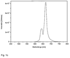
Im Kontext dieser Anmeldung wird als rotes Licht solches Licht bezeichnet, dessen Intensitätsmaximum zwischen 600 und 680 nm Wellenlänge liegt.In the context of this application is referred to as red light such light whose intensity maximum is between 600 and 680 nm wavelength.
Ein weiterer Erfindungsgegenstand ist ein Verfahren zur Herstellung einer Verbindung der Formel I umfassend folgende Schritte:
- a) Mischen von Lutetium-, Scandium-, Calcium-, Aluminium-, Mangan-, Yttrium-, Terbium- und/oder Gadolinium-haltigen Materialien
- b) Zugabe mindestens eines weiteren anorganischen und/oder organischen Stoffes
- c) thermische Behandlung der Mischung.
- a) mixing of lutetium, scandium, calcium, aluminum, manganese, yttrium, terbium and / or gadolinium-containing materials
- b) adding at least one further inorganic and / or organic substance
- c) thermal treatment of the mixture.
Bei der oben genannten thermischen Behandlung erfolgt die Umsetzung üblicherweise bei einer Temperatur oberhalb 800°C. Vorzugsweise erfolgt die thermische Behandlung in einem Mehrstufenprozess, besonders bevorzugt in einem 2-stufigen Prozess, d.h. zuerst wird bei einer Temperatur > 900°C unter Luft kalziniert und anschließend vorzugsweise bei einer Temperatur > 1500°C, besonders bevorzugt bei T = 1600 bis 1800°C. Alternativ kann die Kalzinierung auch unter reduzierenden Bedingungen (z.B. mit Kohlenmonoxid, Formiergas oder Wasserstoff oder Sauerstoffmangel-Atmosphäre) durchgeführt werden.In the above-mentioned thermal treatment, the reaction is usually carried out at a temperature above 800 ° C. Preferably, the thermal treatment is in a multi-stage process, more preferably in a 2-stage process, i. first calcined at a temperature> 900 ° C under air and then preferably at a temperature> 1500 ° C, more preferably at T = 1600 to 1800 ° C. Alternatively, the calcination may also be carried out under reducing conditions (e.g., with carbon monoxide, forming gas or hydrogen or oxygen depleted atmosphere).
Als anorganischer oder organischer Stoff (im Schritt b) wird ein Stoff aus der Gruppe der Ammoniumhalogenide, Erdalkalifluoride wie Calcium-, Strontium- oder Bariumfluorid, (Erd)-Alkalimetallborate, Borsäure, (Erd)Alkalimetallcarbonate oder Ammoniumhydrogencarbonat, Citronensäure, Alkoholate sowie Oxalate und/oder Kieselsäureester wie z.B. TEOS eingesetzt. Bevorzugt wird Citronensäure und ein Oxalat zugesetzt. Gegebenenfalls kann das Oxalat auch schon im Schritt a) zugesetzt werden.An inorganic or organic substance (in step b) is a substance from the group of ammonium halides, alkaline earth fluorides such as calcium, strontium or barium fluoride, (earth) alkali metal borates, boric acid, (earth) alkali metal carbonates or ammonium bicarbonate, Citric acid, alcoholates and oxalates and / or silicic acid esters such as TEOS used. Preferably, citric acid and an oxalate are added. Optionally, the oxalate may also be added in step a).
Die Herstellung der erfindungsgemäßen Leuchtstoffe kann entweder über eine herkömmliche Festkörperdiffusionsmethode (ausgehend von den Oxiden, Nitraten, Carbonaten oder Halogeniden der entsprechenden Erdalkalimetalle, Halbmetalle, Metalle oder Seltenerden) oder nasschemisch aus anorganischen und/oder organischen Metall- und/oder Seltenerd-Salzen mittels Sol-Gel-Verfahren, Copräzipitations- und /oder Trocknungsverfahren erfolgen. Bevorzugt sind erfindungsgemäß nasschemische Verfahren, besonders bevorzugt nasschemisch mittels Zugabe von Zitronensäure.The phosphors according to the invention can be prepared either by a conventional solid-state diffusion method (starting from the oxides, nitrates, carbonates or halides of the corresponding alkaline earth metals, semimetals, metals or rare earths) or wet-chemically from inorganic and / or organic metal and / or rare earth salts by means of sol Gel process, coprecipitation and / or drying process. According to the invention, preference is given to wet-chemical processes, particularly preferably wet-chemical by the addition of citric acid.
Bei den nasschemischen Verfahren über wässrige Vorstufen (Precursoren) der Leuchtstoffe sind folgende Methoden bekannt:
- Cofällung (auch Copräzipitation genannt) mit einer NH4HCO3-Lösung (siehe z.B.
Jander, Blasius Lehrbuch der analyt. u. präp. anorg. Chem. 2002 - Pecchini-Verfahren mit einer Lösung aus Zitronensäure und Ethylenglykol (siehe z.B.
Annual Review of Materials Research Vol. 36: 2006, 281-331 - Combustion-Verfahren unter Verwendung von Harnstoff
- Sprühtrocknung wässriger oder organischer Salzlösungen (Edukte)
- Sprühpyrolyse (auch Spraypyrolyse genannt) wässriger oder organischer Salzlösungen (Edukte)
- Eindampfen von Nitratlösungen und thermischer Umsetzung des Rückstandes
- Fällung mit einer Lösung, die Zitronensäue oder Oxalat enthält
- Co-precipitation (also called coprecipitation) with an NH 4 HCO 3 solution (see, for example , US Pat
Jander, Blasius textbook of the analyt. u. prep. anorg. Chem. 2002 - Pecchini method with a solution of citric acid and ethylene glycol ( see, eg
Annual Review of Materials Research Vol. 36: 2006, 281-331 - Combustion process using urea
- Spray drying of aqueous or organic salt solutions (educts)
- Spray pyrolysis (also called spray pyrolysis) of aqueous or organic salt solutions (educts)
- Evaporation of nitrate solutions and thermal reaction of the residue
- Precipitation with a solution containing citric acid or oxalate
Bei der o.g. Cofällung werden z.B. Chloridlösungen der entsprechenden Leuchtstoffedukte mit einer TEOS/NH4HCO3-Lösung versetzt, wodurch sich der Leuchtstoffprecursor bildet, der anschließend durch eine ein- oder mehrstufige thermische Behandlung in den Leuchtstoff umgewandelt wird.In the above-mentioned coprecipitation, for example, chloride solutions of the corresponding phosphor educts are admixed with a TEOS / NH 4 HCO 3 solution, whereby the phosphor precursor is formed, which is subsequently converted into the phosphor by a one-stage or multistage thermal treatment.
Beim Pecchini-Verfahren werden z.B. Nitratlösungen der entsprechenden Leuchtstoffedukte bei Raumtemperatur mit einem Fällungsreagenz bestehend aus Zitronensäure und Ethylenglykol versetzt und anschließend erhitzt. Durch Erhöhung der Viskosität kommt es zur Leuchtstoffprecursor-Bildung.In the pecchini method, e.g. Nitrate solutions of the corresponding Leuchtstoffedukte at room temperature with a precipitating agent consisting of citric acid and ethylene glycol added and then heated. Increasing the viscosity causes phosphor precursor formation.
Beim bekannten Combustion-Verfahren werden z.B. Nitratlösungen der entsprechenden Edukte in Wasser gelöst, dann unter Rückfluss gekocht und mit Harnstoff versetzt, wodurch sich der Leuchtstoffprecursor langsam bildet.In the known combustion method, e.g. Dissolved nitrate solutions of the corresponding starting materials in water, then boiled under reflux and mixed with urea, whereby the phosphor precursor is formed slowly.
Die Sprühpyrolyse gehört zu den Aerosolverfahren, die durch Versprühen von Lösungen, Suspensionen oder Dispersionen in einen durch unterschiedliche Art und Weise erhitzten Reaktionsraum (Reaktor) sowie die Bildung und Abscheidung von Feststoff- Partikeln gekennzeichnet sind. Im Gegensatz zur Sprühtrocknung mit Heißgastemperaturen < 200°C finden bei der Sprühpyrolyse als Hochtemperatur-Prozess außer der Verdampfung des Lösungsmittels zusätzlich die thermische Zersetzung der verwendeten Edukte (z. B. Salze) sowie die Neubildung von Stoffen (z. B. Oxide, Mischoxide) statt.Spray pyrolysis belongs to the aerosol processes which are characterized by spraying solutions, suspensions or dispersions into a reaction chamber (reactor) which has been heated in different ways, as well as the formation and separation of solid particles. In contrast to spray drying with hot gas temperatures <200 ° C, spray pyrolysis as the high-temperature process is characterized by the thermal decomposition of the educts used (eg salts) and the formation of new substances (eg oxides, mixed oxides ) instead of.
Bei der Fällung mit einer Lösung aus Zitronensäure oder Oxalat werden z.B. Oxide oder Carbonatlösungen der entsprechenden Edukte in konz. HNO3 gelöst und anschließend mit der o.g. Lösung versetzt, bevor dann eingedampft oder filtriert wird. Diese Methode ist erfindungsgemäß bevorzugt.In the precipitation with a solution of citric acid or oxalate, for example, oxides or carbonate solutions of the corresponding reactants in concentrated. Dissolved HNO 3 and then treated with the above solution, then evaporated or filtered. This method is preferred according to the invention.
Die ersten sechs der o.g. Verfahrensvarianten sind ausführlich in der
Die erfindungsgemäßen orange-rot-emittierenden Leuchtstoffe können auch mit grün-emittierenden Leuchtstoffen gemischt werden, wodurch sich solche Mischungen sehr gut für Anwendungen in der Allgemeinbeleuchtung (z.B. für warm-weiße LEDs) und LCD-backlighting eignen.The orange-red emitting phosphors of the present invention may also be mixed with green emitting phosphors, making such blends highly suitable for general lighting applications (e.g., warm white LEDs) and LCD backlighting.
Eine weitere Ausführungsform der vorliegenden Erfindung ist daher eine Mischung enthaltend mindestens eine Verbindung der Formel I und mindestens einen grün-emittierenden Leuchtstoff, wobei dieser vorzugsweise ausgewählt wird aus Ce-dotierten Granaten, vorzugsweise LuAG:Ce, (Sr,Ca)Si2N2O2:Eu, (Sr,Ba)2SiO4:Eu, oder CaSc2O4:Ce,Na.A further embodiment of the present invention is therefore a mixture comprising at least one compound of the formula I and at least one green-emitting phosphor, which is preferably selected from Ce-doped garnets, preferably LuAG: Ce, (Sr, Ca) Si 2 N 2 O 2 : Eu, (Sr, Ba) 2 SiO 4 : Eu, or CaSc 2 O 4 : Ce, Na.
Dabei liegen erfindungsgemäß die Verbindung (bzw. Leuchtstoff) gemäß Formel I und der mindestens eine grün emittierende Leuchtstoff üblicherweise im Gewichtsverhältnis 20:1 bis 1:1 vor. Erfindungsgemäß bevorzugt ist es, wenn der mindestens eine Leuchtstoff der Formel I und der mindestens eine grün emittierende Leuchtstoff im Gewichtsverhältnis 10:1 bis 3:1 und insbesondere bevorzugt 6:1 bis 4:1 vorliegen.According to the invention, the compound (or phosphor) according to formula I and the at least one green emitting phosphor are usually present in a weight ratio of 20: 1 to 1: 1. It is preferred according to the invention for the at least one phosphor of the formula I and the at least one green-emitting phosphor to be present in a weight ratio of 10: 1 to 3: 1 and particularly preferably 6: 1 to 4: 1.
Die Partikelgröße der erfindungsgemäßen Leuchtstoffe beträgt üblicherweise zwischen 50 nm und 30 µm, vorzugsweise zwischen 1 µm und 20 µm.The particle size of the phosphors according to the invention is usually between 50 nm and 30 .mu.m, preferably between 1 .mu.m and 20 .mu.m.
In einer weiteren bevorzugten Ausführungsform besitzen die Leuchtstoffe in Partikelform eine geschlossene Oberflächenbeschichtung, die aus SiO2, TiO2, Al2O3, ZnO, ZrO2 und/oderY2O3 oder Mischoxiden daraus besteht. Diese Oberflächenbeschichtung hat den Vorteil, dass durch eine geeignete Abstufung der Brechungsindices der Beschichtungsmaterialien eine Anpassung des Brechungsindex mit der Umgebung erzielt werden kann. In diesem Fall wird die Streuung des Lichtes an der Oberfläche des Leuchtstoffes verringert und ein größerer Anteil des Lichtes kann in den Leuchtstoff eindringen und dort absorbiert und konvertiert werden. Außerdem ermöglicht es die Brechungsindex-angepasste Oberflächenbeschichtung, dass mehr Licht aus dem Leuchtstoff ausgekoppelt wird, weil die interne Totalreflexion verringert wird.In a further preferred embodiment, the phosphors in particle form have a closed surface coating consisting of SiO 2 , TiO 2 , Al 2 O 3 , ZnO, ZrO 2 and / or Y 2 O 3 or mixed oxides thereof. This surface coating has the advantage that by a suitable Grading the refractive indices of the coating materials, an adjustment of the refractive index can be achieved with the environment. In this case, the scattering of the light at the surface of the phosphor is reduced and a larger proportion of the light can penetrate into the phosphor where it is absorbed and converted. In addition, the refractive index matched surface coating allows more light to be coupled out of the phosphor because the total internal reflection is reduced.
Zudem ist eine geschlossene Schicht dann vorteilhaft, wenn der Leuchtstoff verkapselt werden muss. Dies kann erforderlich sein, um einer Empfindlichkeit des Leuchtstoffes oder Teilen davon gegen diffundierendes Wasser oder andere Materialien in der unmittelbaren Umgebung zu entgegnen. Ein weiterer Grund für die Verkapselung mit einer geschlossenen Hülle ist eine thermische Entkoppelung des eigentlichen Leuchtstoffes von der Wärme, die im Chip entsteht. Diese Wärme führt zu einer Verringerung der Fluoreszenzlichtausbeute des Leuchtstoffes und kann auch die Farbe des Fluoreszenzlichts beeinflussen. Schließlich ist es möglich durch eine solche Beschichtung die Effizienz des Leuchtstoffes zu erhöhen, indem im Leuchtstoff entstehende Gitterschwingungen in ihrer Ausbreitung an die Umgebung gehindert werden.In addition, a closed layer is advantageous if the phosphor has to be encapsulated. This may be necessary to counter sensitivity of the phosphor or parts thereof to diffusing water or other materials in the immediate environment. Another reason for the encapsulation with a closed shell is a thermal decoupling of the actual phosphor from the heat that arises in the chip. This heat leads to a reduction in the fluorescent light output of the phosphor and may also affect the color of the fluorescent light. Finally, it is possible by such a coating to increase the efficiency of the phosphor by preventing lattice vibrations arising in the phosphor from propagating to the environment.
Außerdem bevorzugt ist es, wenn die Leuchtstoffe eine poröse Oberflächenbeschichtung besitzen, die aus SiO2, TiO2, Al2O3, ZnO, ZrO2 und/oder Y2O3 oder Mischoxide daraus oder aus der Leuchtstoffzusammensetzung besteht. Diese porösen Beschichtungen bieten die Möglichkeit, den Brechungsindex einer Einfachschicht weiter zu reduzieren. Die Herstellung solcher poröser Beschichtungen kann nach drei herkömmlichen Methoden geschehen, wie sie in
In einer weiteren bevorzugten Ausführungsform besitzen die Leuchtstoffpartikel eine Oberfläche, die funktionelle Gruppen trägt, welche eine chemische Anbindung an die Umgebung, vorzugsweise bestehend aus Epoxy- oder Silikonharz ermöglicht. Diese funktionellen Gruppen können z.B. über Oxogruppen angebundene Ester oder andere Derivate sein, die mit Bestandteilen der Bindemittel auf Basis von Epoxiden und / oder Silikonen Verknüpfungen eingehen können. Solche Oberflächen haben den Vorteil, dass eine homogene Einmischung der Leuchtstoffe in das Bindemittel ermöglicht wird. Des Weiteren können dadurch die rheologischen Eigenschaften des Systems Leuchtstoff / Bindemittel und auch die Topfzeiten in einem gewissen Masse eingestellt werden. Damit wird die Verarbeitung der Gemische vereinfacht.In a further preferred embodiment, the phosphor particles have a surface which carries functional groups which allow a chemical connection to the environment, preferably consisting of epoxy or silicone resin. These functional groups may e.g. oxo group-attached esters or other derivatives which can form linkages with components based on epoxides and / or silicones. Such surfaces have the advantage that a homogeneous mixing of the phosphors is made possible in the binder. Furthermore, the rheological properties of the system phosphor / binder and also the pot life can be adjusted to a certain extent. This simplifies the processing of the mixtures.
Da die auf einem LED Chip aufgebrachte Leuchtstoffschicht vorzugsweise aus einem Gemisch von Silikon und homogenen Leuchtstoffpartikeln besteht, welches im Volumenguss aufgebracht wird, und das Silikon eine Oberflächenspannung aufweist, ist diese Leuchtstoffschicht auf mikroskopischer Ebene nicht einheitlich bzw. ist die Dicke der Schicht nicht durchweg konstant. Dies ist in der Regel auch der Fall wenn der Leuchtstoff nicht nach dem Volumengussverfahren, sondern im sogenannten Chip-Level-Konversionsverfahren, bei dem eine hochkonzentrierte, dünne Leuchtstoffschicht mit Hilfe von elektrostatischen Methoden direkt auf die Oberfläche des Chips appliziert wird, aufgebracht wird.Since the phosphor layer applied to an LED chip preferably consists of a mixture of silicone and homogeneous phosphor particles, which is applied by volume casting, and the silicone has a surface tension, this phosphor layer is not uniform at the microscopic level or the thickness of the layer is not consistently constant , This is usually also the case when the phosphor is not applied by the volume casting method, but in the so-called chip-level conversion method in which a highly concentrated, thin phosphor layer is applied directly to the surface of the chip by means of electrostatic methods.
Mit Hilfe des oben genannten Verfahrens können beliebige äußere Formen der Leuchtstoffpartikel hergestellt werden, wie sphärische Partikel, Plättchen und strukturierte Materialien und Keramiken.With the aid of the abovementioned method, it is possible to produce any external forms of the phosphor particles, such as spherical particles, platelets and structured materials and ceramics.
Die Herstellung von plättchenförmigen Leuchtstoffen als weitere bevorzugte Ausführungsform geschieht nach herkömmlichen Verfahren aus den entsprechenden Metall- und/oder Seltenerd-Salzen. Das Herstellverfahren ist in
Die dem LED Chip zugewandte Oberfläche des erfindungsgemäßen plättchenförmigen Leuchtstoffes kann mit einer Beschichtung versehen werden, welche entspiegelnd in Bezug auf die von dem LED Chip emittierte Primärstrahlung wirkt. Dies führt zu einer Verringerung der Rückstreuung der Primärstrahlung, wodurch diese besser in den erfindungsgemäßen Leuchtstoffkörper eingekoppelt werden kann.
Hierfür eignen sich beispielsweise brechzahlangepasste Beschichtungen, die eine folgende Dicke d aufweisen müssen: d = [Wellenlänge der Primärstrahlung des LED Chips /(4* Brechzahl der Leuchtstoffkeramik)], s. beispielsweise
The surface of the platelet-shaped phosphor according to the invention facing the LED chip can be provided with a coating which is anti-reflective with respect to the primary radiation emitted by the LED chip. This leads to a reduction in the backscattering of the primary radiation, as a result of which it can be better coupled into the phosphor body according to the invention.
For example, refractive index-adapted coatings, which must have a following thickness d, are suitable for this: d = [wavelength of the primary radiation of the LED chip / (4 * refractive index of the phosphor ceramic)], see FIG. for example
Die Herstellung der erfindungsgemäßen Leuchtstoffe in Form von keramischen Körpern erfolgt analog nach dem in der
Die Seitenflächen des keramischen Leuchtstoffkörpers können mit einem Leicht- oder Edelmetall, vorzugsweise Aluminium oder Silber verspiegelt werden. Die Verspiegelung bewirkt, dass kein Licht lateral aus dem Leuchtstoffkörper austritt. Lateral austretendes Licht kann den aus der LED auszukoppelnden Lichtstrom verringern. Die Verspiegelung des keramischen Leuchtstoffkörpers erfolgt in einem Prozessschritt nach der isostatischen Verpressung zu Stangen oder Plättchen, wobei vor der Verspiegelung eventuell ein Schneiden der Stangen oder Plättchen in die erforderliche Größe erfolgen kann. Die Seitenflächen werden hierzu z.B. mit einer Lösung aus Silbernitrat und Glucose benetzt und anschließend bei erhöhter Temperatur einer Ammoniak-Atmosphäre ausgesetzt. Hierbei bildet sich z.B. ein silberner Belag auf den Seitenflächen aus.
Alternativ bieten sich auch stromlose Metallisierungsverfahren an, siehe beispielsweise
Der keramische Leuchtstoffkörper kann, falls erforderlich, mit einer Wasserglaslösung auf dem Untergrund eines LED Chip fixiert werden.The side surfaces of the ceramic phosphor body can be mirrored with a light or noble metal, preferably aluminum or silver. The mirroring causes no light to emerge laterally from the phosphor body. Lateral exiting light can reduce the luminous flux to be coupled out of the LED. The mirroring of the ceramic phosphor body is carried out in a process step after the isostatic pressing to rods or plates, which may be done before the mirroring cutting the rods or plates into the required size. For this purpose, the side surfaces are wetted, for example, with a solution of silver nitrate and glucose, and then exposed to an ammonia atmosphere at elevated temperature. Here, for example, forms a silver coating on the side surfaces.
Alternatively, also electroless metallization offer, see for example
The ceramic phosphor body can, if necessary, be fixed with a water glass solution on the substrate of an LED chip.
In einer weiteren Ausführungsform besitzt der keramische Leuchtstoffkörper auf der, einem LED Chip entgegengesetzten Seite eine strukturierte (z.B. pyramidale) Oberfläche. Somit kann möglichst viel Licht aus dem Leuchtstoffkörper ausgekoppelt werden. Die strukturierte Oberfläche auf dem Leuchtstoffkörper wird dadurch hergestellt, in dem beim isostatischen Verpressen das Presswerkzeug eine strukturierte Pressplatte aufweist und dadurch eine Struktur in die Oberfläche prägt. Strukturierte Oberflächen sind dann gewünscht, wenn möglichst dünne Leuchtstoffkörper bzw. Plättchen hergestellt werden sollen. Die Pressbedingungen sind dem Fachmann bekannt (siehe
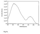
Die Anregbarkeit der erfindungsgemäßen Leuchtstoffe erstreckt sich zudem über einen weiten Bereich, der von etwa 410 nm bis 530 nm, bevorzugt 430 nm bis zu etwa 500 nm reicht. Damit sind diese Leuchtstoffe nicht nur zur Anregung durch violett oder blau emittierende Lichtquellen wie LEDs oder konventionelle Entladungslampen (z.B. auf Hg-Basis) geeignet, sondern auch für Lichtquellen wie solche, welche die blaue In3+ -Linie bei 451 nm ausnutzen.The excitability of the phosphors according to the invention also extends over a wide range, ranging from about 410 nm to 530 nm, preferably 430 nm to about 500 nm. Thus, these phosphors are not only suitable for excitation by violet or blue emitting light sources such as LEDs or conventional discharge lamps (eg based on Hg), but also for light sources such as those which exploit the blue In 3+ line at 451 nm.
Ein weiterer Gegenstand der vorliegenden Erfindung ist eine Lichtquelle, dadurch gekennzeichnet, dass diese einen Halbleiter und mindestens eine Verbindung bzw. einen Leuchtstoff nach Formel I enthält.Another object of the present invention is a light source, characterized in that it contains a semiconductor and at least one compound or a phosphor according to formula I.
Ein weiterer Gegenstand der vorliegenden Erfindung ist eine Lichtquelle dadurch gekennzeichnet, dass diese einen Halbleiter und mindestens eine Verbindung nach Formel I sowie mindestens einen grün emittierenden Leuchtstoff enthält. Vorzugsweise ist diese Beleuchtungseinheit weiß emittierend oder emittiert Licht mit einem bestimmten Farbpunkt (Color-on-demand-Prinzip).Another object of the present invention is a light source characterized in that it contains a semiconductor and at least one compound of formula I and at least one green-emitting phosphor. Preferably, this lighting unit emits white or emits light with a certain color point (color-on-demand principle).
Unter dem color-on-demand Konzept versteht man die Realisierung von Licht eines bestimmten Farbpunktes mit einer pcLED (= phosphor converted LED) unter Einsatz eines oder mehrer Leuchtstoffe. Dieses Konzept wird z.B. verwendet, um bestimmte Corporate Designs, z.B. für beleuchtete Firmenlogos, Marken etc. zu erzeugen.The color-on-demand concept is the realization of light of a certain color point with a pcLED (= phosphor converted LED) using one or more phosphors. This concept is e.g. used to design certain corporate designs, e.g. for illuminated company logos, brands etc.
In einer bevorzugten Ausführungsform der erfindungsgemäßen Lichtquelle handelt es sich bei dem Halbleiter um ein lumineszentes IndiumAluminiumGalliumNitrid, insbesondere der Formel IniGajAlkN, wobei 0 ≤ i, 0 ≤ j, 0 ≤ k, und i+j+k=1 ist.In a preferred embodiment of the light source according to the invention, the semiconductor is a luminescent one Indium-aluminum gallium nitride, in particular of the formula In i Ga j Al k N, where 0 ≦ i, 0 ≦ j, 0 ≦ k, and i + j + k = 1.
In einer weiteren bevorzugten Ausführungsform der erfindungsgemäßen Lichtquelle handelt es sich bei der Lichtquelle um eine lumineszente auf ZnO, TCO (Transparent conducting oxide), ZnSe oder SiC basierende Anordnung oder auch um eine auf einer organischen lichtemittierenden Schicht basierende Anordnung (OLED).In a further preferred embodiment of the light source according to the invention, the light source is a luminescent arrangement based on ZnO, TCO (transparent conducting oxide), ZnSe or SiC or else an arrangement based on an organic light-emitting layer (OLED).
In einer weiteren bevorzugten Ausführungsform der erfindungsgemäßen Lichtquelle handelt es sich bei der Lichtquelle um eine Quelle, die Elektrolumineszenz und/oder Photolumineszenz zeigt. Weiterhin kann es sich bei der Lichtquelle auch um eine Plasma- oder Entladungsquelle handeln.In a further preferred embodiment of the light source according to the invention, the light source is a source which exhibits electroluminescence and / or photoluminescence. Furthermore, the light source may also be a plasma or discharge source.
Dem Fachmann sind mögliche Formen von derartigen Lichtquellen bekannt. Es kann sich hierbei um lichtemittierende LED-Chips unterschiedlichen Aufbaus handeln.The person skilled in possible forms of such light sources are known. These may be light-emitting LED chips of different construction.
Die erfindungsgemäßen Leuchtstoffe können entweder in einem Harz dispergiert (z.B. Epoxy- oder Siliconharz), oder bei geeigneten Größenverhältnissen direkt auf der Lichtquelle angeordnet werden oder aber von dieser, je nach Anwendung, entfernt angeordnet sein (letztere Anordnung schließt auch die "Remote phosphor Technologie" mit ein). Die Vorteile der "Remote phosphor Technologie" sind dem Fachmann bekannt und z.B. der folgenden Publikation zu entnehmen:
Weitere Erfindungsgegenstände sind eine Beleuchtungseinheit, insbesondere zur Hintergrundbeleuchtung von Anzeigevorrichtungen, die dadurch gekennzeichnet ist, dass sie mindestens eine oben beschriebene Lichtquelle enthält und entsprechende Anzeigevorrichtungen, insbesondere Flüssigkristallanzeigevorrichtung (LC Display), mit einer Hintergrundbeleuchtung, die dadurch gekennzeichnet sind, dass sie mindestens eine solche Beleuchtungseinheit enthalten.Further subjects of the invention are a lighting unit, in particular for the backlight of display devices, which is characterized in that it contains at least one light source described above and corresponding display devices, in particular Liquid crystal display device (LC display), with a backlight, characterized in that they contain at least one such lighting unit.
Weiterhin bevorzugt ist eine Beleuchtungseinheit, insbesondere zur Allgemeinbeleuchtung, die dadurch gekennzeichnet ist, dass sie einen CRI (=color rendering index) > 60, vorzugsweise > 70, noch bevorzugter >85 aufweist. CRI-Werte > 85 können allerdings nur realisiert werden, wenn der erfindungsgemäße rote Leuchtstoff nach Formel I zusätzlich mit grünen Leuchtstoffen in der LED kombiniert wird.Further preferred is a lighting unit, in particular for general lighting, which is characterized in that it has a CRI (= color rendering index)> 60, preferably> 70, more preferably> 85. However, CRI values> 85 can only be realized if the red phosphor according to the invention according to formula I is additionally combined with green phosphors in the LED.
In einer weiteren Ausführungsform ist es bevorzugt, wenn die optische Ankopplung der Beleuchtungseinheit zwischen dem Leuchtstoff und dem Halbleiter durch eine lichtleitende Anordnung realisiert wird.
Dadurch ist es möglich, dass an einem zentralen Ort der Halbleiter installiert wird und dieser mittels lichtleitender Vorrichtungen, wie beispielsweise lichtleitenden Fasern, an den Leuchtstoff optisch angekoppelt ist. Auf diese Weise lassen sich den Beleuchtungswünschen angepasste Leuchten lediglich bestehend aus einem oder unterschiedlichen Leuchtstoffen, die zu einem Leuchtschirm angeordnet sein können, und einem Lichtleiter, der an die Lichtquelle angekoppelt ist, realisieren. Auf diese Weise ist es möglich, eine starke Lichtquelle an einen für die elektrische Installation günstigen Ort zu platzieren und ohne weitere elektrische Verkabelung, sondern nur durch Verlegen von Lichtleitern an beliebigen Orten Leuchten aus Leuchtstoffen, welche an die Lichtleiter gekoppelt sind, zu installieren.In a further embodiment, it is preferred if the optical coupling of the illumination unit between the phosphor and the semiconductor is realized by a light-conducting arrangement.
This makes it possible that the semiconductor is installed at a central location and this is optically coupled to the phosphor by means of light-conducting devices, such as, for example, photoconductive fibers. In this way, the lighting requirements adapted lights can only be realized consisting of one or different phosphors, which can be arranged to form a luminescent screen, and a light guide, which is coupled to the light source. In this way it is possible to place a strong light source at a convenient location for the electrical installation and to install without further electrical wiring, but only by laying fiber optics at any location lights of phosphors, which are coupled to the light guide.
Ein weiterer Gegenstand der vorliegenden Erfindung ist die Verwendung der erfindungsgemäßen Leuchtstoffe zur teilweisen oder vollständigen Konversion der blauen oder im nahen UV-liegenden Emission einer Lumineszenzdiode.Another object of the present invention is the use of the phosphors according to the invention for the partial or complete conversion of blue or in the near UV emission of a light-emitting diode.
Weiterhin bevorzugt ist die Verwendung der erfindungsgemäßen Leuchtstoffe zur Konversion der blauen oder im nahen UV-liegenden Emission in sichtbare weiße Strahlung. Weiterhin ist die Verwendung der erfindungsgemäßen Leuchtstoffe zur Konversion der Primärstrahlung in einen bestimmten Farbpunkt nach dem "Color on demand"-Konzept bevorzugt.Further preferred is the use of the phosphors according to the invention for the conversion of blue or near-UV emission into visible white radiation. Furthermore, the use of the phosphors according to the invention for converting the primary radiation into a specific color point according to the "color on demand" concept is preferred.
Ein weiterer Gegenstand der vorliegenden Erfindung ist die Verwendung der erfindungsgemäßen Leuchtstoffe in Elektrolumineszenz-Materialien, wie beispielsweise Elektrolumineszenz-Folien (auch Leuchtfolien oder Lichtfolien genannt), in denen beispielsweise Zinksulfid oder Zinksulfid dotiert mit Mn2+, Cu+, oder Ag+ als Emitter eingesetzt wird, die im gelbgrünen Bereich emittieren. Die Anwendungsbereiche der Elektrolumineszenz-Folie sind z.B. Werbung, Displayhintergrundbeleuchtung in Flüssigkristallbildschirmen (LC-Displays) und Dünnschichttransistor-Displays (TFT-Displays), selbstleuchtende KFZ-Kennzeichenschilder, Bodengrafik (in Verbindung mit einem tritt- und rutschfesten Laminat), in Anzeigen- und/oder Bedienelementen beispielsweise in Automobilen, Zügen, Schiffen und Flugzeugen oder auch Haushalts-, Garten-, Mess- oder Sport- und Freizeitgeräten.Another object of the present invention is the use of the phosphors according to the invention in electroluminescent materials, such as electroluminescent films (also called phosphors or light foils) in which, for example, zinc sulfide or zinc sulfide doped with Mn 2+ , Cu + , or Ag + as an emitter is used, which emit in the yellow-green area. The fields of application of the electroluminescent film are, for example, advertising, display backlighting in liquid crystal displays (LC displays) and thin-film transistor displays (TFT displays), self-illuminating license plate labels, floor graphics (in conjunction with a non-slip and non-slip laminate), in display and / or controls for example in automobiles, trains, ships and aircraft or household, gardening, measuring or sports and leisure equipment.
Die folgenden Beispiele sollen die vorliegende Erfindung verdeutlichen. Sie sind jedoch keinesfalls als limitierend zu betrachten. Alle Verbindungen oder Komponenten, die in den Zubereitungen verwendet werden können, sind entweder bekannt und kommerziell erhältlich oder können nach bekannten Methoden synthetisiert werden. Die in den Beispielen angegebenen Temperaturen gelten immer in °C. Es versteht sich weiterhin von selbst, dass sich sowohl in der Beschreibung als auch in den Beispielen die zugegebenen Mengen der Komponenten in den Zusammensetzungen immer zu insgesamt 100% addieren. Gegebene Prozentangaben sind immer im gegebenen Zusammenhang zu sehen. Sie beziehen sich üblicherweise aber immer auf die Masse der angegebenen Teil- oder Gesamtmenge.The following examples are intended to illustrate the present invention. However, they are by no means to be considered limiting. Any compounds or components that can be used in the formulations are either known and commercially available or can be synthesized by known methods. The temperatures given in the examples always apply in ° C. It goes without saying that both in the description and in the examples, the added amounts of the components in the compositions always add up to a total of 100%. Given percentages are always to be seen in the given context. she Usually, however, always refer to the mass of the specified partial or total quantity.
5,0125 g (0,0126 mol) Y2O3, 0,0042g CaCO3 (4,2115*10-5 mol) und 0,0075g (4,2115*10-5 mol) MnC2O4*2H2O werden in konz. HNO3 unter Erwärmen gelöst. Zu dieser Lösung werden 15,7827 g (0,0427 mol) Al(NO3)3*9H2O in 300 mL Wasser gegeben und anschließend 10g Citronensäure, wobei 30 Min. gerührt wird. Die Lösung wird im Trockenschrank bei 150°C über Nacht getrocknet und der entstandene Citratprecursor fein gemörsert. Das Pulver wird bei 1000°C für 3 h kalziniert und dann 5 h an Luft bei 1750°C kalziniert.5.0125 g (0.0126 mol) Y 2 O 3 , 0.0042 g CaCO 3 (4.2115 * 10 -5 mol) and 0.0075 g (4.2115 * 10 -5 mol) MnC 2 O 4 * 2H 2 O are in conc. ENT 3 dissolved with heating. 15.7827 g (0.0427 mol) of Al (NO 3 ) 3 .9H 2 O in 300 ml of water are added to this solution, followed by 10 g of citric acid, the mixture being stirred for 30 min. The solution is dried in an oven at 150 ° C overnight and the resulting citrate precursors finely ground. The powder is calcined at 1000 ° C for 3 h and then calcined in air at 1750 ° C for 5 h.
5,0125 g Lu2O3 und 0.5808 g Sc2O3 werden in konz. HNO3 unter Erwärmen gelöst und dann wird 0.0042 g CaCO3 zugegeben.
14.2028 Al(NO3)3*9H2O und 0.0075 g Manganoxalat werden in dest. Wasser gelöst und zu der vorherigen Lösung gegeben.
Zu dieser Lösung werden 10 g Citronensäure gegeben und unter Erwärmen 30 min gerührt. Die Lösung wird im Trockenschrank bei 130 °C über Nacht eingeengt und der entstandene Citratprecursor fein gemörsert. Das Pulver wird bei 1000°C 3 h kalziniert und dann 4 h bei 1700°C an Luft kalziniert.5.0125 g of Lu 2 O 3 and 0.5808 g of Sc 2 O 3 are added in conc. Dissolved HNO 3 with heating and then 0.0042 g CaCO 3 is added.
14.2028 Al (NO 3 ) 3 * 9H 2 O and 0.0075 g of manganese oxalate are dissolved in dist. Dissolved water and added to the previous solution.
To this solution, 10 g of citric acid are added and stirred with heating for 30 min. The solution is concentrated in a drying oven at 130 ° C. overnight and the resulting citrate precursor finely ground. The powder is calcined at 1000 ° C for 3 h and then calcined at 1700 ° C for 4 h in air.
2,507 g Lu2O3 und 1,4226 g Y2O3 werden in konz. HNO3 unter Erwärmen gelöst und 4,2 mg CaCO3 werden zugegeben. 15,783 g Al(NO3)3*9H2O und 7,5 mg Manganoxalat werden in dest. Wasser gelöst und zu der vorherigen Lösung gegeben. In diese Lösung werden 10 g Citronensäure gegeben und unter Erwärmen 30 min gerührt. Die Lösung wird im Trockenschrank bei 130°C über Nacht eingeengt und der entstandene Citratprecursor gemörsert. Das Pulver wird bei 1000°C für 3 h kalziniert und dann für 4 h bei 1700°C an Luft kalziniert2.507 g of Lu 2 O 3 and 1.4226 g of Y 2 O 3 are dissolved in conc. Dissolved HNO 3 with heating and 4.2 mg CaCO 3 are added. 15.783 g of Al (NO 3 ) 3 * 9H 2 O and 7.5 mg of manganese oxalate are dissolved in dist. Dissolved water and added to the previous solution. In this solution, 10 g of citric acid and stirred with heating for 30 min. The solution is concentrated in a drying oven at 130 ° C. overnight and the resulting citrate precursor is ground. The powder is calcined at 1000 ° C for 3 h and then calcined for 4 h at 1700 ° C in air
23.507 g Lu2O3 und 2,284 g Gd2O3 werden in konz. HNO3 unter Erwärmen gelöst, dann werden 4,2 mg CaCO3 zu dieser Lösung gegeben.
15,783 g Al(NO3)3*9H2O und 7,5 mg Manganoxalat werden in dest. Wasser gelöst und zu der vorherigen Lösung gegeben. In diese Lösung werden 10 g Menge Citronensäure gegeben und unter Erwärmen 30 min gerührt. Die Lösung wird im Trockenschrank bei 130°C über Nacht eingeengt und der entstandene Citratprecursor gemörsert. Das Pulver wird bei 1000 °C für 3 h kalziniert und dann 4 h bei 1700°C an Luft kalziniert23.507 g of Lu 2 O 3 and 2.284 g of Gd 2 O 3 are added in conc. Dissolved HNO 3 with heating, then 4.2 mg of CaCO 3 are added to this solution.
15.783 g of Al (NO 3 ) 3 * 9H 2 O and 7.5 mg of manganese oxalate are dissolved in dist. Dissolved water and added to the previous solution. In this solution, 10 g amount of citric acid are added and stirred with heating for 30 min. The solution is concentrated in a drying oven at 130 ° C. overnight and the resulting citrate precursor is ground. The powder is calcined at 1000 ° C for 3 h and then calcined at 1700 ° C for 4 h in air
Ein Leuchtstoff aus den Beispielen 1 bis 4 wird in einem Taumelmischer mit einem 2-Komponenten Silikon (OE6550 der Fa. Dow Corning) gemischt, so dass gleiche Mengen des Leuchtstoffs in den beiden Komponenten des Silikons dispergiert sind, die Gesamtkonzentration der Leuchtstoffmischung im Silikon beträgt 8 Gew.-%.A phosphor from Examples 1 to 4 is mixed in a tumble mixer with a 2-component silicone (OE6550 Fa. Dow Corning), so that equal amounts of the phosphor are dispersed in the two components of the silicone, the total concentration of the phosphor mixture in the silicone 8% by weight.
5 ml jeder der beiden Leuchtstoff enthaltenden Silikon Komponenten werden homogen miteinander gemischt und in einen Dispenser überführt. Mit Hilfe des Dispensers werden leere LED packages von der Fa. OSA optoelectronics, Berlin, welche einen 100 µm2 großen GaN Chip enthalten, befüllt. Danach werden die LEDs in eine Wärmekammer gestellt, um über 1 h bei 150°C das Silikon zu verfestigen.
CIE x und CIE y stehen für die Koordinaten in dem dem Fachmann geläufigen CIE Normfarbdiagramm (hier Normalbeobachter 1931), mit denen die Farbe einer Lichtquelle beschrieben wird.
Alle oben aufgeführten Größen werden nach dem Fachmann geläufigen Methoden aus Emissionsspektren der Lichtquelle berechnet.CIE x and CIE y represent the coordinates in the CIE standard color diagram familiar to the person skilled in the art (here standard observer 1931), which describes the color of a light source.
All the variables listed above are calculated from emission spectra of the light source according to methods familiar to the person skilled in the art.
Es sei darauf hingewiesen, dass bei den nachfolgenden 16 FigurenBeschreibungen die Leuchtstoffzusammensetzungen jeweils durch die verkürzte Schreibweise angegeben sind, wie sie in der Laserphysik üblich sind. Das heißt z.B. Lu2.995Al4.995O12: Mn0.005Ca0.005 wird in verkürzter Schreibweise als "Lu3Al5O12: Mn4+(0,1%), Ca2+(0,1%)" angegeben.
-
Fig. 1a : zeigt einen Vergleich der Röntgendiffraktogramme von Leuchtstoffen der Zusammensetzung Lu3Al5O12: Mn4+(0,1%), Ca2+(0,1%) im Vergleich zu dem Diffraktogramm der Referenz Lu3Al5O12. Die Röntgendiffraktogramme wurden mit einem Rigaku Miniflux II unter Verwendung von Cu-K-alpha-Strahlung aufgenommen. Der Messbereich 2Theta betrug 10 - 60°. -
Fig. 1 b : zeigt ein Anregungsspektrum von Lu3Al5O12: Mn4+(0,1%), Ca2+(0,1%) Das Spektrum wurden an einer halbunendlich dicken Pulverschicht mit einem Edinburgh Instruments FL920 Spektrometer unter Verwendung einer Xe-Hochdrucklampe und eines Hamamatsu Photomultipliers bei Raumtemperatur aufgenommen. -
Fig. 1 c: zeigt das normierte Emissionsspektrum von Lu3Al5O12: Mn4+(0,1%), Ca2+(0,1%). Das Spektrum wurden an einer halbunendlich dicken Pulverschicht mit einem Edinburgh Instruments FL920 Spektrometer unter Verwendung einer Xe-Hochdrucklampe und eines Hamamatsu Photomultipliers bei Raumtemperatur aufgenommen. -
Fig. 1d : zeigt ein Reflexionsspektrum von Lu3Al5O12: Mn4+(0,1%), Ca2+(0,1%)
Das Spektrum wurden an einer halbunendlich dicken Pulverschicht mit einem Edinburgh Instruments FS920 Spektrometer in einer Ulbricht.-Kugel unter Verwendung einer Xe-Hochdrucklampe und eines Hamamatsu Photomultipliers bei Raumtemperatur aufgenommen. -
Fig. 2a : zeigt einen Vergleich der Röntgendiffraktogramme von Leuchtstoffen der Zusammensetzung Lu3Al4.5Sc0.5O12:Mn(0.1%),Ca(0.1 %) im Vergleich zu dem Diffraktogramm der Referenz Lu3Al5O12. Die Röntgendiffraktogramme wurden mit einem Rigaku Miniflux II unter Verwendung von Cu-K-alpha-Strahlung aufgenommen. Der Messbereich 2Theta betrug 10 - 60°. -
Fig. 2b : zeigt ein Anregungsspektrum von Lu3Al4.5Sc0.5O12:Mn(0.1%) ,Ca(0.1%). Das Spektrum wurden an einer halbunendlich dicken Pulverschicht mit einem Edinburgh Instruments FL920 Spektrometer unter Verwendung einer Xe-Hochdrucklampe und eines Hamamatsu Photomultipliers bei Raumtemperatur aufgenommen. -
Fig. 2c : zeigt das normierte Emissionsspektrum von Lu3Al4.5Sc0.5O12:Mn(0.1%), Ca(0.1 %). Das Spektrum wurden an einer halbunendlich dicken Pulverschicht mit einem Edinburgh Instruments FL920 Spektrometer unter Verwendung einer Xe-Hochdrucklampe und eines Hamamatsu Photomultipliers bei Raumtemperatur aufgenommen.
-
Fig. 2d : zeigt ein Reflexionsspektrum von Lu3Al4.5Sc0.5O12:Mn(0.1%), Ca(0.1 %). Das Spektrum wurden an einer halbunendlich dicken Pulverschicht mit einem Edinburgh Instruments FS920 Spektrometer in einer Ulbricht.-Kugel unter Verwendung einer Xe-Hochdrucklampe und eines Hamamatsu Photomultipliers bei Raumtemperatur aufgenommen. -
Fig. 3a : zeigt einen Vergleich der Röntgendiffraktogramme von Leuchtstoffen der Zusammensetzung (Lu0.5Y0.5)3Al5O12:Mn(0.1%), Ca(0.1 %) im Vergleich zu dem Diffraktogramm der Referenz Lu3Al5O12. Die Röntgendiffraktogramme wurden mit einem Rigaku Miniflux II unter Verwendung von Cu-K-alpha-Strahlung aufgenommen. Der Messbereich 2Theta betrug 10 - 60 °. -
Fig. 3b : zeigt ein Anregungsspektrum von (Lu0.5Y0.5)3Al5O12:Mn(0.1%) Ca(0.1%). Das Spektrum wurden an einer halbunendlich dicken Pulverschicht mit einem Edinburgh Instruments FL920 Spektrometer unter Verwendung einer Xe-Hochdrucklampe und eines Hamamatsu Photomultipliers bei Raumtemperatur aufgenommen. -
Fig. 3c : zeigt das normierte Emissionsspektrum von (Lu0.5Y0.5)3Al5O12:Mn(0.1%),Ca(0.1%). Das Spektrum wurden an einer halbunendlich dicken Pulverschicht mit einem Edinburgh Instruments FL920 Spektrometer unter Verwendung einer Xe-Hochdrucklampe und eines Hamamatsu Photomultipliers bei Raumtemperatur aufgenommen. -
Fig. 3d : zeigt ein Reflexionsspektrum von (Lu0.5Y0.5)3Al5O12:Mn(0.1%), Ca(0.1 %). Das Spektrum wurden an einer halbunendlich dicken Pulverschicht mit einem Edinburgh Instruments FS920 Spektrometer in einer Ulbricht.-Kugel unter Verwendung einer Xe-Hochdrucklampe und eines Hamamatsu Photomultipliers bei Raumtemperatur aufgenommen. -
Fig. 4a : zeigt einen Vergleich der Röntgendiffraktogramme von Leuchtstoffen der Zusammensetzung (Lu0.5Gd0.5)3Al5O12:Mn(0.1%), Ca(0.1 %) im Vergleich zu dem Diffraktogramm der Referenz Lu3Al5O12. Die Röntgendiffraktogramme wurden mit einem Rigaku Miniflux II unter Verwendung von Cu-K-alpha-Strahlung aufgenommen. Der Messbereich 2Theta betrug 10 - 60°. -
Fig. 4b : zeigt ein Anregungsspektrum von (Lu0.5Gd0.5)3Al5O12:Mn(0.1%), Ca(0.1%). Das Spektrum wurden an einer halbunendlich dicken Pulverschicht mit einem Edinburgh Instruments FL920 Spektrometer unter Verwendung einer Xe-Hochdrucklampe und eines Hamamatsu Photomultipliers bei Raumtemperatur aufgenommen. -
Fig. 4c : zeigt das normierte Emissionsspektrum von (Lu0.5Gd0.5)3Al5O12:Mn(0.1%),Ca(0.1%). Das Spektrum wurden an einer halbunendlich dicken Pulverschicht mit einem Edinburgh Instruments FL920 Spektrometer unter Verwendung einer Xe-Hochdrucklampe und eines Hamamatsu Photomultipliers bei Raumtemperatur aufgenommen. -
Fig. 4d : zeigt ein Reflexionsspektrum von (Lu0.5Gd0.5)3Al5O12:Mn(0.1%), Ca(0.1 %). Das Spektrum wurden an einer halbunendlich dicken Pulverschicht mit einem Edinburgh Instruments FS920 Spektrometer in einer Ulbricht.-Kugel unter Verwendung einer Xe-Hochdrucklampe und eines Hamamatsu Photomultipliers bei Raumtemperatur aufgenommen.
-
Fig. 1a Figure 3 shows a comparison of the X-ray diffraction patterns of phosphors of the composition Lu 3 Al 5 O 12 : Mn 4+ (0.1%), Ca 2+ (0.1%) compared to the diffractogram of the reference Lu 3 Al 5 O 12 . The X-ray diffractograms were taken with a Rigaku Miniflux II using Cu-K-alpha radiation. The measuring range 2Theta was 10 - 60 °. -
Fig. 1 b : shows an excitation spectrum of Lu 3 Al 5 O 12 : Mn 4+ (0.1%), Ca 2+ (0.1%) The spectrum was measured on a semi-infinite thick powder layer using an Edinburgh Instruments FL920 spectrometer using a Xe High-pressure lamp and a Hamamatsu photomultiplier recorded at room temperature. -
Fig. 1 c: shows the normalized emission spectrum of Lu 3 Al 5 O 12 : Mn 4+ (0.1%), Ca 2+ (0.1%). The spectrum was recorded on a semi-infinite thick powder layer with an Edinburgh Instruments FL920 spectrometer using a high pressure Xe lamp and a Hamamatsu photomultiplier at room temperature. -
Fig. 1d : shows a reflectance spectrum of Lu 3 Al 5 O 12 : Mn 4+ (0.1%), Ca 2+ (0.1%)
The spectrum was recorded on a semi-infinite thick powder layer with an Edinburgh Instruments FS920 spectrometer in an Ulbricht sphere using a high pressure Xe lamp and a Hamamatsu photomultiplier at room temperature. -
Fig. 2a FIG. 2 shows a comparison of the X-ray diffractograms of phosphors of the composition Lu 3 Al 4.5 Sc 0.5 O 12 : Mn (0.1%), Ca (0.1%) in comparison to the diffractogram of the reference Lu 3 Al 5 O 12 . The X-ray diffractograms were taken with a Rigaku Miniflux II using Cu-K-alpha radiation. The measuring range 2Theta was 10 - 60 °. -
Fig. 2b : shows an excitation spectrum of Lu 3 Al 4 . 5 Sc 0 . 5 O 12 : Mn (0.1%), Ca (0.1%). The spectrum was recorded on a semi-infinite thick powder layer with an Edinburgh Instruments FL920 spectrometer using a high pressure Xe lamp and a Hamamatsu photomultiplier at room temperature. -
Fig. 2c : shows the normalized emission spectrum of Lu 3 Al 4 . 5 Sc 0 . 5 O 12 : Mn (0.1%), Ca (0.1%). The spectrum was recorded on a semi-infinite thick powder layer with an Edinburgh Instruments FL920 spectrometer using a high pressure Xe lamp and a Hamamatsu photomultiplier at room temperature.
-
Fig. 2d : shows a reflectance spectrum of Lu 3 Al 4.5 Sc 0.5 O 12 : Mn (0.1%), Ca (0.1%). The spectrum was recorded on a semi-infinite thick powder layer with an Edinburgh Instruments FS920 spectrometer in an Ulbricht sphere using a high pressure Xe lamp and a Hamamatsu photomultiplier at room temperature. -
Fig. 3a FIG. 2 shows a comparison of the X-ray diffraction patterns of phosphors of the composition (Lu 0.5 Y 0.5 ) 3 Al 5 O 12 : Mn (0.1%), Ca (0.1%) compared to the diffractogram of the reference Lu 3 Al 5 O 12 . The X-ray diffractograms were taken with a Rigaku Miniflux II using Cu-K-alpha radiation. The measuring range 2Theta was 10 - 60 °. -
Fig. 3b : shows an excitation spectrum of (Lu 0.5 Y 0 .5 ) 3 Al 5 O 12 : Mn (0.1%) Ca (0.1%). The spectrum was recorded on a semi-infinite thick powder layer with an Edinburgh Instruments FL920 spectrometer using a high pressure Xe lamp and a Hamamatsu photomultiplier at room temperature. -
Fig. 3c : Shows the normalized emission spectra of (Lu 0 5 Y 0.5.) 3 Al 5 O 12: Mn (0.1%), Ca (0.1%). The spectrum was recorded on a semi-infinite thick powder layer with an Edinburgh Instruments FL920 spectrometer using a high pressure Xe lamp and a Hamamatsu photomultiplier at room temperature. -
Fig. 3d : shows a reflectance spectrum of (Lu 0.5 Y 0.5 ) 3 Al 5 O 12 : Mn (0.1%), Ca (0.1%). The spectrum was recorded on a semi-infinite thick powder layer with an Edinburgh Instruments FS920 spectrometer in an Ulbricht sphere using a high pressure Xe lamp and a Hamamatsu photomultiplier at room temperature. -
Fig. FIG. 4 shows a comparison of the X-ray diffractograms of phosphors of the composition (Lu 0.5 Gd 0.5 ) 3 Al 5 O 12 : Mn (0.1%), Ca (0.1%) compared to the diffractogram of the reference Lu 3 Al 5 O 12 . The X-ray diffractograms were taken with a Rigaku Miniflux II using Cu-K-alpha radiation. The measuring range 2Theta was 10 - 60 °.4a -
Fig. 4b : shows an excitation spectrum of (Lu 0.5 Gd 0.5 ) 3 Al 5 O 12 : Mn (0.1%), Ca (0.1%). The spectrum was recorded on a semi-infinite thick powder layer with an Edinburgh Instruments FL920 spectrometer using a high pressure Xe lamp and a Hamamatsu photomultiplier at room temperature. -
Fig. 4c : shows the normalized emission spectrum of (Lu 0.5 Gd 0.5 ) 3 Al 5 O 12 : Mn (0.1%), Ca (0.1%). The spectrum was recorded on a semi-infinite thick powder layer with an Edinburgh Instruments FL920 spectrometer using a high pressure Xe lamp and a Hamamatsu photomultiplier at room temperature. -
Fig. 4d : shows a reflectance spectrum of (Lu 0.5 Gd 0.5 ) 3 Al 5 O 12 : Mn (0.1%), Ca (0.1%). The spectrum was recorded on a semi-infinite thick powder layer with an Edinburgh Instruments FS920 spectrometer in an Ulbricht sphere using a high pressure Xe lamp and a Hamamatsu photomultiplier at room temperature.
Claims (12)
- Compound of the formula I
LU3-x-z AxAl5-y-zSCyO12: MnzCaz (I)
whereA stands for Y, Gd or Tbx stands for a value from the range from 0 to 2.90y stands for a value from the range from 0 to 0.50z stands for a value from the range from 0.005 to 0.05. - Compound according to Claim 1, characterised in that x stands for a value from the range from 0 to 2.0, preferably from the range from 0.10 to 0.90.
- Compound according to Claim 1 or 2, characterised in that y stands for a value from the range from 0.10 to 0.45, preferably from the range from 0.20 to 0.40.
- Process for the preparation of a compound according to one or more of Claims 1 to 3 comprising the following process steps:a) mixing of lutetium-, scandium-, calcium-, aluminium-, manganese-, yttrium-, terbium- and/or gadolinium-containing materials,b) addition of at least one further inorganic and/or organic substance,c) thermal treatment of the mixture.
- Process according to Claim 4, characterised in that the inorganic or organic substances (process step b) are selected from the group of the ammonium halides, alkaline-earth metal fluorides, such as calcium fluoride, strontium fluoride or barium fluoride, alkaline-earth or alkali-metal borates, boric acid, alkaline-earth or alkali-metal carbonates or ammonium hydrogencarbonate, citric acid, alcoholates, as well as oxalates and/or silicates, such as, for example, TEOS.
- Process according to Claim 4 and/or 5, characterised in that the thermal treatment of the mixture is carried out in multiple steps, preferably in 2 steps.
- Light source, characterised in that it comprises a semiconductor and at least one compound of the formula I according to one or more of Claims 1 to 3.
- Light source according to Claim 7, characterised in that the semiconductor is a luminescent indium aluminium gallium nitride, in particular of the formula IniGajAlkN, where 0 ≤ i, 0 ≤ j, 0 ≤ k, and i+j+k=1.
- Lighting unit, characterised in that it contains at least one light source according to Claim 7 or 8.
- Lighting unit according to Claim 9, characterised in that the optical coupling between the phosphor and the semiconductor is achieved by a light-conducting arrangement.
- Display device, in particular liquid-crystal display device (LC display), characterised in that it contains at least one lighting unit according to Claim 9 or 10.
- Use of at least one compound according to one or more of Claims 1 to 3 as conversion phosphor for the partial or complete conversion of the blue or near-UV emission from a luminescent diode.
Applications Claiming Priority (2)
| Application Number | Priority Date | Filing Date | Title |
|---|---|---|---|
| DE102010047474A DE102010047474A1 (en) | 2010-10-06 | 2010-10-06 | Mn-activated phosphors |
| PCT/EP2011/004652 WO2012045393A1 (en) | 2010-10-06 | 2011-09-16 | Mn-activated phosphors |
Publications (2)
| Publication Number | Publication Date |
|---|---|
| EP2625247A1 EP2625247A1 (en) | 2013-08-14 |
| EP2625247B1 true EP2625247B1 (en) | 2016-11-30 |
Family
ID=44677842
Family Applications (1)
| Application Number | Title | Priority Date | Filing Date |
|---|---|---|---|
| EP11761009.7A Not-in-force EP2625247B1 (en) | 2010-10-06 | 2011-09-16 | Mn-activated phosphors |
Country Status (7)
| Country | Link |
|---|---|
| US (1) | US9080104B2 (en) |
| EP (1) | EP2625247B1 (en) |
| JP (1) | JP5912121B2 (en) |
| KR (1) | KR20130111562A (en) |
| CN (1) | CN103154196A (en) |
| DE (1) | DE102010047474A1 (en) |
| WO (1) | WO2012045393A1 (en) |
Families Citing this family (6)
| Publication number | Priority date | Publication date | Assignee | Title |
|---|---|---|---|---|
| US20160108311A1 (en) * | 2013-05-02 | 2016-04-21 | Merck Patent Gmbh | Phosphors |
| KR102355081B1 (en) | 2014-12-26 | 2022-01-26 | 삼성전자주식회사 | Method of manufacturing fluoride phosphor, light emitting device, display apparatus and illumination apparatus |
| CN107810145A (en) | 2015-06-29 | 2018-03-16 | 陶氏环球技术有限责任公司 | Method for manufacturing the flexible container with microcapillary distribution system |
| CN105331364B (en) * | 2015-10-12 | 2017-09-05 | 杭州电子科技大学 | A kind of YAG:Mn red fluorescence powders with and its preparation method and application |
| DE102015015355A1 (en) * | 2015-12-01 | 2017-06-01 | Merck Patent Gmbh | Mn-activated phosphors |
| KR102419770B1 (en) * | 2016-05-20 | 2022-07-13 | 가부시키가이샤 한도오따이 에네루기 켄큐쇼 | Light-emitting device and electronic device |
Family Cites Families (15)
| Publication number | Priority date | Publication date | Assignee | Title |
|---|---|---|---|---|
| US4019884A (en) | 1976-01-22 | 1977-04-26 | Corning Glass Works | Method for providing porous broad-band antireflective surface layers on chemically-durable borosilicate glasses |
| NL181063C (en) * | 1976-05-13 | 1987-06-01 | Philips Nv | LUMINESCENT SCREEN; LOW-PRESSURE MERCURY DISCHARGE LAMP; PROCESS FOR PREPARING A LUMINESCENT MATERIAL |
| NL7700419A (en) * | 1977-01-17 | 1978-07-19 | Philips Nv | MAGNETIC BUBBLE DOMAIN MATERIAL. |
| JP3242561B2 (en) | 1995-09-14 | 2001-12-25 | メルク・ジヤパン株式会社 | Flaky aluminum oxide, pearlescent pigment and method for producing the same |
| US6556336B2 (en) * | 1997-07-24 | 2003-04-29 | Scientific Materials, Corp. | Optical laser light limiter |
| DE29820384U1 (en) * | 1998-11-06 | 1999-01-14 | Opto System Gmbh | Luminous or display element with mixed-colored, especially white light |
| AU2002338733B2 (en) | 2001-09-21 | 2008-09-04 | Merck Patent Gmbh | Novel hybrid sol for producing abrasion-resistant SiO2 antireflection coatings |
| DE10213294B4 (en) * | 2002-03-25 | 2015-05-13 | Osram Gmbh | Use of a UV-resistant polymer in optoelectronics and outdoor applications, UV-resistant polymer and optical component |
| CN1255506C (en) * | 2003-11-13 | 2006-05-10 | 北京有色金属研究总院 | Boron-containing luminescent powder for LED, preparing method thereof and electric light source therefrom |
| DE102006027306B4 (en) * | 2006-06-06 | 2013-10-17 | Schott Ag | Process for the preparation of a glass ceramic with a garnet phase and use of the glass ceramic produced thereafter |
| DE102006027133A1 (en) | 2006-06-12 | 2007-12-13 | Merck Patent Gmbh | Process for the preparation of garnet phosphors in a pulsation reactor |
| DE102006037730A1 (en) | 2006-08-11 | 2008-02-14 | Merck Patent Gmbh | LED conversion phosphors in the form of ceramic bodies |
| DE102006054331A1 (en) | 2006-11-17 | 2008-05-21 | Merck Patent Gmbh | Phosphor body based on platelet-shaped substrates |
| US9133392B2 (en) * | 2010-07-22 | 2015-09-15 | Osram Opto Semiconductors Gmbh | Garnet material, method for its manufacturing and radiation-emitting component comprising the garnet material |
| TWI486254B (en) * | 2010-09-20 | 2015-06-01 | Nitto Denko Corp | Light emissive ceramic laminate and method of making same |
-
2010
- 2010-10-06 DE DE102010047474A patent/DE102010047474A1/en not_active Withdrawn
-
2011
- 2011-09-16 EP EP11761009.7A patent/EP2625247B1/en not_active Not-in-force
- 2011-09-16 JP JP2013532060A patent/JP5912121B2/en not_active Expired - Fee Related
- 2011-09-16 WO PCT/EP2011/004652 patent/WO2012045393A1/en active Application Filing
- 2011-09-16 KR KR1020137011771A patent/KR20130111562A/en active IP Right Grant
- 2011-09-16 CN CN2011800481843A patent/CN103154196A/en active Pending
- 2011-09-16 US US13/877,954 patent/US9080104B2/en not_active Expired - Fee Related
Also Published As
| Publication number | Publication date |
|---|---|
| US9080104B2 (en) | 2015-07-14 |
| CN103154196A (en) | 2013-06-12 |
| KR20130111562A (en) | 2013-10-10 |
| US20130193472A1 (en) | 2013-08-01 |
| DE102010047474A1 (en) | 2012-04-12 |
| EP2625247A1 (en) | 2013-08-14 |
| JP2014502243A (en) | 2014-01-30 |
| WO2012045393A1 (en) | 2012-04-12 |
| JP5912121B2 (en) | 2016-04-27 |
Similar Documents
| Publication | Publication Date | Title |
|---|---|---|
| EP2616523B1 (en) | Silicophosphate luminophores | |
| EP2576725B1 (en) | Luminescent substances | |
| EP2129740B1 (en) | Method for producing illuminants based on orthosilicates for pcleds | |
| EP2115092B1 (en) | Luminophores made of doped garnets for pcleds | |
| EP2596078B1 (en) | Aluminate luminescent substances | |
| EP2914688B1 (en) | Eu-activated luminophores | |
| EP2129741B1 (en) | METHOD FOR PRODUCING PHOSPHORS CONSISTING OF ORTHOSILICATES FOR pcLEDs | |
| EP2350231A1 (en) | Doped garnet fluorescent substance having red shift for pc leds | |
| EP2324096B1 (en) | Codoped 1-1-2 nitrides | |
| EP2625247B1 (en) | Mn-activated phosphors | |
| DE102009032711A1 (en) | Co-doped silicooxynitrides | |
| EP2596681B1 (en) | Carbodiimide luminescent substances | |
| DE102009050542A1 (en) | Sm-activated aluminate and borate phosphors | |
| EP2619283B1 (en) | Silicate fluorescent substance |
Legal Events
| Date | Code | Title | Description |
|---|---|---|---|
| PUAI | Public reference made under article 153(3) epc to a published international application that has entered the european phase |
Free format text: ORIGINAL CODE: 0009012 |
|
| 17P | Request for examination filed |
Effective date: 20130305 |
|
| AK | Designated contracting states |
Kind code of ref document: A1 Designated state(s): AL AT BE BG CH CY CZ DE DK EE ES FI FR GB GR HR HU IE IS IT LI LT LU LV MC MK MT NL NO PL PT RO RS SE SI SK SM TR |
|
| RIN1 | Information on inventor provided before grant (corrected) |
Inventor name: BLEISE, ANDRE Inventor name: WINKLER, HOLGER Inventor name: JUESTEL, THOMAS |
|
| DAX | Request for extension of the european patent (deleted) | ||
| 17Q | First examination report despatched |
Effective date: 20140317 |
|
| GRAP | Despatch of communication of intention to grant a patent |
Free format text: ORIGINAL CODE: EPIDOSNIGR1 |
|
| RIC1 | Information provided on ipc code assigned before grant |
Ipc: C09K 11/77 20060101AFI20160620BHEP Ipc: H01L 33/50 20100101ALI20160620BHEP |
|
| INTG | Intention to grant announced |
Effective date: 20160706 |
|
| GRAS | Grant fee paid |
Free format text: ORIGINAL CODE: EPIDOSNIGR3 |
|
| GRAA | (expected) grant |
Free format text: ORIGINAL CODE: 0009210 |
|
| AK | Designated contracting states |
Kind code of ref document: B1 Designated state(s): AL AT BE BG CH CY CZ DE DK EE ES FI FR GB GR HR HU IE IS IT LI LT LU LV MC MK MT NL NO PL PT RO RS SE SI SK SM TR |
|
| REG | Reference to a national code |
Ref country code: CH Ref legal event code: EP Ref country code: GB Ref legal event code: FG4D Free format text: NOT ENGLISH |
|
| REG | Reference to a national code |
Ref country code: AT Ref legal event code: REF Ref document number: 849797 Country of ref document: AT Kind code of ref document: T Effective date: 20161215 |
|
| REG | Reference to a national code |
Ref country code: IE Ref legal event code: FG4D Free format text: LANGUAGE OF EP DOCUMENT: GERMAN |
|
| REG | Reference to a national code |
Ref country code: DE Ref legal event code: R096 Ref document number: 502011011258 Country of ref document: DE |
|
| PG25 | Lapsed in a contracting state [announced via postgrant information from national office to epo] |
Ref country code: LV Free format text: LAPSE BECAUSE OF FAILURE TO SUBMIT A TRANSLATION OF THE DESCRIPTION OR TO PAY THE FEE WITHIN THE PRESCRIBED TIME-LIMIT Effective date: 20161130 |
|
| REG | Reference to a national code |
Ref country code: LT Ref legal event code: MG4D |
|
| REG | Reference to a national code |
Ref country code: NL Ref legal event code: MP Effective date: 20161130 |
|
| PG25 | Lapsed in a contracting state [announced via postgrant information from national office to epo] |
Ref country code: NO Free format text: LAPSE BECAUSE OF FAILURE TO SUBMIT A TRANSLATION OF THE DESCRIPTION OR TO PAY THE FEE WITHIN THE PRESCRIBED TIME-LIMIT Effective date: 20170228 Ref country code: LT Free format text: LAPSE BECAUSE OF FAILURE TO SUBMIT A TRANSLATION OF THE DESCRIPTION OR TO PAY THE FEE WITHIN THE PRESCRIBED TIME-LIMIT Effective date: 20161130 Ref country code: SE Free format text: LAPSE BECAUSE OF FAILURE TO SUBMIT A TRANSLATION OF THE DESCRIPTION OR TO PAY THE FEE WITHIN THE PRESCRIBED TIME-LIMIT Effective date: 20161130 Ref country code: GR Free format text: LAPSE BECAUSE OF FAILURE TO SUBMIT A TRANSLATION OF THE DESCRIPTION OR TO PAY THE FEE WITHIN THE PRESCRIBED TIME-LIMIT Effective date: 20170301 |
|
| PG25 | Lapsed in a contracting state [announced via postgrant information from national office to epo] |
Ref country code: HR Free format text: LAPSE BECAUSE OF FAILURE TO SUBMIT A TRANSLATION OF THE DESCRIPTION OR TO PAY THE FEE WITHIN THE PRESCRIBED TIME-LIMIT Effective date: 20161130 Ref country code: ES Free format text: LAPSE BECAUSE OF FAILURE TO SUBMIT A TRANSLATION OF THE DESCRIPTION OR TO PAY THE FEE WITHIN THE PRESCRIBED TIME-LIMIT Effective date: 20161130 Ref country code: RS Free format text: LAPSE BECAUSE OF FAILURE TO SUBMIT A TRANSLATION OF THE DESCRIPTION OR TO PAY THE FEE WITHIN THE PRESCRIBED TIME-LIMIT Effective date: 20161130 Ref country code: PL Free format text: LAPSE BECAUSE OF FAILURE TO SUBMIT A TRANSLATION OF THE DESCRIPTION OR TO PAY THE FEE WITHIN THE PRESCRIBED TIME-LIMIT Effective date: 20161130 Ref country code: PT Free format text: LAPSE BECAUSE OF FAILURE TO SUBMIT A TRANSLATION OF THE DESCRIPTION OR TO PAY THE FEE WITHIN THE PRESCRIBED TIME-LIMIT Effective date: 20170330 Ref country code: FI Free format text: LAPSE BECAUSE OF FAILURE TO SUBMIT A TRANSLATION OF THE DESCRIPTION OR TO PAY THE FEE WITHIN THE PRESCRIBED TIME-LIMIT Effective date: 20161130 |
|
| PG25 | Lapsed in a contracting state [announced via postgrant information from national office to epo] |
Ref country code: NL Free format text: LAPSE BECAUSE OF FAILURE TO SUBMIT A TRANSLATION OF THE DESCRIPTION OR TO PAY THE FEE WITHIN THE PRESCRIBED TIME-LIMIT Effective date: 20161130 |
|
| PG25 | Lapsed in a contracting state [announced via postgrant information from national office to epo] |
Ref country code: RO Free format text: LAPSE BECAUSE OF FAILURE TO SUBMIT A TRANSLATION OF THE DESCRIPTION OR TO PAY THE FEE WITHIN THE PRESCRIBED TIME-LIMIT Effective date: 20161130 Ref country code: CZ Free format text: LAPSE BECAUSE OF FAILURE TO SUBMIT A TRANSLATION OF THE DESCRIPTION OR TO PAY THE FEE WITHIN THE PRESCRIBED TIME-LIMIT Effective date: 20161130 Ref country code: SK Free format text: LAPSE BECAUSE OF FAILURE TO SUBMIT A TRANSLATION OF THE DESCRIPTION OR TO PAY THE FEE WITHIN THE PRESCRIBED TIME-LIMIT Effective date: 20161130 Ref country code: DK Free format text: LAPSE BECAUSE OF FAILURE TO SUBMIT A TRANSLATION OF THE DESCRIPTION OR TO PAY THE FEE WITHIN THE PRESCRIBED TIME-LIMIT Effective date: 20161130 Ref country code: EE Free format text: LAPSE BECAUSE OF FAILURE TO SUBMIT A TRANSLATION OF THE DESCRIPTION OR TO PAY THE FEE WITHIN THE PRESCRIBED TIME-LIMIT Effective date: 20161130 |
|
| PG25 | Lapsed in a contracting state [announced via postgrant information from national office to epo] |
Ref country code: SM Free format text: LAPSE BECAUSE OF FAILURE TO SUBMIT A TRANSLATION OF THE DESCRIPTION OR TO PAY THE FEE WITHIN THE PRESCRIBED TIME-LIMIT Effective date: 20161130 Ref country code: IT Free format text: LAPSE BECAUSE OF FAILURE TO SUBMIT A TRANSLATION OF THE DESCRIPTION OR TO PAY THE FEE WITHIN THE PRESCRIBED TIME-LIMIT Effective date: 20161130 Ref country code: BG Free format text: LAPSE BECAUSE OF FAILURE TO SUBMIT A TRANSLATION OF THE DESCRIPTION OR TO PAY THE FEE WITHIN THE PRESCRIBED TIME-LIMIT Effective date: 20170228 |
|
| REG | Reference to a national code |
Ref country code: DE Ref legal event code: R097 Ref document number: 502011011258 Country of ref document: DE |
|
| PLBE | No opposition filed within time limit |
Free format text: ORIGINAL CODE: 0009261 |
|
| STAA | Information on the status of an ep patent application or granted ep patent |
Free format text: STATUS: NO OPPOSITION FILED WITHIN TIME LIMIT |
|
| PGFP | Annual fee paid to national office [announced via postgrant information from national office to epo] |
Ref country code: DE Payment date: 20170912 Year of fee payment: 7 |
|
| 26N | No opposition filed |
Effective date: 20170831 |
|
| PG25 | Lapsed in a contracting state [announced via postgrant information from national office to epo] |
Ref country code: SI Free format text: LAPSE BECAUSE OF FAILURE TO SUBMIT A TRANSLATION OF THE DESCRIPTION OR TO PAY THE FEE WITHIN THE PRESCRIBED TIME-LIMIT Effective date: 20161130 |
|
| REG | Reference to a national code |
Ref country code: CH Ref legal event code: PL |
|
| GBPC | Gb: european patent ceased through non-payment of renewal fee |
Effective date: 20170916 |
|
| PG25 | Lapsed in a contracting state [announced via postgrant information from national office to epo] |
Ref country code: MC Free format text: LAPSE BECAUSE OF FAILURE TO SUBMIT A TRANSLATION OF THE DESCRIPTION OR TO PAY THE FEE WITHIN THE PRESCRIBED TIME-LIMIT Effective date: 20161130 |
|
| REG | Reference to a national code |
Ref country code: IE Ref legal event code: MM4A |
|
| REG | Reference to a national code |
Ref country code: BE Ref legal event code: MM Effective date: 20170930 |
|
| PG25 | Lapsed in a contracting state [announced via postgrant information from national office to epo] |
Ref country code: LU Free format text: LAPSE BECAUSE OF NON-PAYMENT OF DUE FEES Effective date: 20170916 |
|
| REG | Reference to a national code |
Ref country code: FR Ref legal event code: ST Effective date: 20180531 |
|
| PG25 | Lapsed in a contracting state [announced via postgrant information from national office to epo] |
Ref country code: CH Free format text: LAPSE BECAUSE OF NON-PAYMENT OF DUE FEES Effective date: 20170930 Ref country code: LI Free format text: LAPSE BECAUSE OF NON-PAYMENT OF DUE FEES Effective date: 20170930 Ref country code: GB Free format text: LAPSE BECAUSE OF NON-PAYMENT OF DUE FEES Effective date: 20170916 Ref country code: IE Free format text: LAPSE BECAUSE OF NON-PAYMENT OF DUE FEES Effective date: 20170916 |
|
| PG25 | Lapsed in a contracting state [announced via postgrant information from national office to epo] |
Ref country code: FR Free format text: LAPSE BECAUSE OF NON-PAYMENT OF DUE FEES Effective date: 20171002 Ref country code: BE Free format text: LAPSE BECAUSE OF NON-PAYMENT OF DUE FEES Effective date: 20170930 |
|
| PG25 | Lapsed in a contracting state [announced via postgrant information from national office to epo] |
Ref country code: MT Free format text: LAPSE BECAUSE OF FAILURE TO SUBMIT A TRANSLATION OF THE DESCRIPTION OR TO PAY THE FEE WITHIN THE PRESCRIBED TIME-LIMIT Effective date: 20161130 |
|
| REG | Reference to a national code |
Ref country code: AT Ref legal event code: MM01 Ref document number: 849797 Country of ref document: AT Kind code of ref document: T Effective date: 20170916 |
|
| PG25 | Lapsed in a contracting state [announced via postgrant information from national office to epo] |
Ref country code: AT Free format text: LAPSE BECAUSE OF NON-PAYMENT OF DUE FEES Effective date: 20170916 |
|
| REG | Reference to a national code |
Ref country code: DE Ref legal event code: R119 Ref document number: 502011011258 Country of ref document: DE |
|
| PG25 | Lapsed in a contracting state [announced via postgrant information from national office to epo] |
Ref country code: HU Free format text: LAPSE BECAUSE OF FAILURE TO SUBMIT A TRANSLATION OF THE DESCRIPTION OR TO PAY THE FEE WITHIN THE PRESCRIBED TIME-LIMIT; INVALID AB INITIO Effective date: 20110916 |
|
| PG25 | Lapsed in a contracting state [announced via postgrant information from national office to epo] |
Ref country code: DE Free format text: LAPSE BECAUSE OF NON-PAYMENT OF DUE FEES Effective date: 20190402 |
|
| PG25 | Lapsed in a contracting state [announced via postgrant information from national office to epo] |
Ref country code: CY Free format text: LAPSE BECAUSE OF NON-PAYMENT OF DUE FEES Effective date: 20161130 |
|
| PG25 | Lapsed in a contracting state [announced via postgrant information from national office to epo] |
Ref country code: MK Free format text: LAPSE BECAUSE OF FAILURE TO SUBMIT A TRANSLATION OF THE DESCRIPTION OR TO PAY THE FEE WITHIN THE PRESCRIBED TIME-LIMIT Effective date: 20161130 |
|
| PG25 | Lapsed in a contracting state [announced via postgrant information from national office to epo] |
Ref country code: TR Free format text: LAPSE BECAUSE OF FAILURE TO SUBMIT A TRANSLATION OF THE DESCRIPTION OR TO PAY THE FEE WITHIN THE PRESCRIBED TIME-LIMIT Effective date: 20161130 |
|
| PG25 | Lapsed in a contracting state [announced via postgrant information from national office to epo] |
Ref country code: AL Free format text: LAPSE BECAUSE OF FAILURE TO SUBMIT A TRANSLATION OF THE DESCRIPTION OR TO PAY THE FEE WITHIN THE PRESCRIBED TIME-LIMIT Effective date: 20161130 Ref country code: IS Free format text: LAPSE BECAUSE OF FAILURE TO SUBMIT A TRANSLATION OF THE DESCRIPTION OR TO PAY THE FEE WITHIN THE PRESCRIBED TIME-LIMIT Effective date: 20170330 |