EP2616523B1 - Silicophosphate luminophores - Google Patents
Silicophosphate luminophores Download PDFInfo
- Publication number
- EP2616523B1 EP2616523B1 EP11751816.7A EP11751816A EP2616523B1 EP 2616523 B1 EP2616523 B1 EP 2616523B1 EP 11751816 A EP11751816 A EP 11751816A EP 2616523 B1 EP2616523 B1 EP 2616523B1
- Authority
- EP
- European Patent Office
- Prior art keywords
- phosphor
- range
- compound
- mixture
- formula
- Prior art date
- Legal status (The legal status is an assumption and is not a legal conclusion. Google has not performed a legal analysis and makes no representation as to the accuracy of the status listed.)
- Not-in-force
Links
Images


Classifications
-
- C—CHEMISTRY; METALLURGY
- C09—DYES; PAINTS; POLISHES; NATURAL RESINS; ADHESIVES; COMPOSITIONS NOT OTHERWISE PROVIDED FOR; APPLICATIONS OF MATERIALS NOT OTHERWISE PROVIDED FOR
- C09K—MATERIALS FOR MISCELLANEOUS APPLICATIONS, NOT PROVIDED FOR ELSEWHERE
- C09K11/00—Luminescent, e.g. electroluminescent, chemiluminescent materials
- C09K11/08—Luminescent, e.g. electroluminescent, chemiluminescent materials containing inorganic luminescent materials
- C09K11/0883—Arsenides; Nitrides; Phosphides
-
- C—CHEMISTRY; METALLURGY
- C09—DYES; PAINTS; POLISHES; NATURAL RESINS; ADHESIVES; COMPOSITIONS NOT OTHERWISE PROVIDED FOR; APPLICATIONS OF MATERIALS NOT OTHERWISE PROVIDED FOR
- C09K—MATERIALS FOR MISCELLANEOUS APPLICATIONS, NOT PROVIDED FOR ELSEWHERE
- C09K11/00—Luminescent, e.g. electroluminescent, chemiluminescent materials
- C09K11/08—Luminescent, e.g. electroluminescent, chemiluminescent materials containing inorganic luminescent materials
- C09K11/59—Luminescent, e.g. electroluminescent, chemiluminescent materials containing inorganic luminescent materials containing silicon
-
- C—CHEMISTRY; METALLURGY
- C09—DYES; PAINTS; POLISHES; NATURAL RESINS; ADHESIVES; COMPOSITIONS NOT OTHERWISE PROVIDED FOR; APPLICATIONS OF MATERIALS NOT OTHERWISE PROVIDED FOR
- C09K—MATERIALS FOR MISCELLANEOUS APPLICATIONS, NOT PROVIDED FOR ELSEWHERE
- C09K11/00—Luminescent, e.g. electroluminescent, chemiluminescent materials
- C09K11/08—Luminescent, e.g. electroluminescent, chemiluminescent materials containing inorganic luminescent materials
- C09K11/70—Luminescent, e.g. electroluminescent, chemiluminescent materials containing inorganic luminescent materials containing phosphorus
- C09K11/71—Luminescent, e.g. electroluminescent, chemiluminescent materials containing inorganic luminescent materials containing phosphorus also containing alkaline earth metals
- C09K11/712—Halogenides
-
- C—CHEMISTRY; METALLURGY
- C09—DYES; PAINTS; POLISHES; NATURAL RESINS; ADHESIVES; COMPOSITIONS NOT OTHERWISE PROVIDED FOR; APPLICATIONS OF MATERIALS NOT OTHERWISE PROVIDED FOR
- C09K—MATERIALS FOR MISCELLANEOUS APPLICATIONS, NOT PROVIDED FOR ELSEWHERE
- C09K11/00—Luminescent, e.g. electroluminescent, chemiluminescent materials
- C09K11/08—Luminescent, e.g. electroluminescent, chemiluminescent materials containing inorganic luminescent materials
- C09K11/77—Luminescent, e.g. electroluminescent, chemiluminescent materials containing inorganic luminescent materials containing rare earth metals
- C09K11/7728—Luminescent, e.g. electroluminescent, chemiluminescent materials containing inorganic luminescent materials containing rare earth metals containing europium
- C09K11/77347—Silicon Nitrides or Silicon Oxynitrides
-
- C—CHEMISTRY; METALLURGY
- C09—DYES; PAINTS; POLISHES; NATURAL RESINS; ADHESIVES; COMPOSITIONS NOT OTHERWISE PROVIDED FOR; APPLICATIONS OF MATERIALS NOT OTHERWISE PROVIDED FOR
- C09K—MATERIALS FOR MISCELLANEOUS APPLICATIONS, NOT PROVIDED FOR ELSEWHERE
- C09K11/00—Luminescent, e.g. electroluminescent, chemiluminescent materials
- C09K11/08—Luminescent, e.g. electroluminescent, chemiluminescent materials containing inorganic luminescent materials
- C09K11/77—Luminescent, e.g. electroluminescent, chemiluminescent materials containing inorganic luminescent materials containing rare earth metals
- C09K11/7728—Luminescent, e.g. electroluminescent, chemiluminescent materials containing inorganic luminescent materials containing rare earth metals containing europium
- C09K11/77348—Silicon Aluminium Nitrides or Silicon Aluminium Oxynitrides
-
- C—CHEMISTRY; METALLURGY
- C09—DYES; PAINTS; POLISHES; NATURAL RESINS; ADHESIVES; COMPOSITIONS NOT OTHERWISE PROVIDED FOR; APPLICATIONS OF MATERIALS NOT OTHERWISE PROVIDED FOR
- C09K—MATERIALS FOR MISCELLANEOUS APPLICATIONS, NOT PROVIDED FOR ELSEWHERE
- C09K11/00—Luminescent, e.g. electroluminescent, chemiluminescent materials
- C09K11/08—Luminescent, e.g. electroluminescent, chemiluminescent materials containing inorganic luminescent materials
- C09K11/77—Luminescent, e.g. electroluminescent, chemiluminescent materials containing inorganic luminescent materials containing rare earth metals
- C09K11/7783—Luminescent, e.g. electroluminescent, chemiluminescent materials containing inorganic luminescent materials containing rare earth metals containing two or more rare earth metals one of which being europium
- C09K11/77922—Silicates
-
- C—CHEMISTRY; METALLURGY
- C09—DYES; PAINTS; POLISHES; NATURAL RESINS; ADHESIVES; COMPOSITIONS NOT OTHERWISE PROVIDED FOR; APPLICATIONS OF MATERIALS NOT OTHERWISE PROVIDED FOR
- C09K—MATERIALS FOR MISCELLANEOUS APPLICATIONS, NOT PROVIDED FOR ELSEWHERE
- C09K11/00—Luminescent, e.g. electroluminescent, chemiluminescent materials
- C09K11/08—Luminescent, e.g. electroluminescent, chemiluminescent materials containing inorganic luminescent materials
- C09K11/77—Luminescent, e.g. electroluminescent, chemiluminescent materials containing inorganic luminescent materials containing rare earth metals
- C09K11/7783—Luminescent, e.g. electroluminescent, chemiluminescent materials containing inorganic luminescent materials containing rare earth metals containing two or more rare earth metals one of which being europium
- C09K11/7795—Phosphates
- C09K11/7796—Phosphates with alkaline earth metals
-
- F—MECHANICAL ENGINEERING; LIGHTING; HEATING; WEAPONS; BLASTING
- F21—LIGHTING
- F21V—FUNCTIONAL FEATURES OR DETAILS OF LIGHTING DEVICES OR SYSTEMS THEREOF; STRUCTURAL COMBINATIONS OF LIGHTING DEVICES WITH OTHER ARTICLES, NOT OTHERWISE PROVIDED FOR
- F21V9/00—Elements for modifying spectral properties, polarisation or intensity of the light emitted, e.g. filters
- F21V9/30—Elements containing photoluminescent material distinct from or spaced from the light source
-
- H—ELECTRICITY
- H01—ELECTRIC ELEMENTS
- H01L—SEMICONDUCTOR DEVICES NOT COVERED BY CLASS H10
- H01L33/00—Semiconductor devices with at least one potential-jump barrier or surface barrier specially adapted for light emission; Processes or apparatus specially adapted for the manufacture or treatment thereof or of parts thereof; Details thereof
- H01L33/48—Semiconductor devices with at least one potential-jump barrier or surface barrier specially adapted for light emission; Processes or apparatus specially adapted for the manufacture or treatment thereof or of parts thereof; Details thereof characterised by the semiconductor body packages
- H01L33/50—Wavelength conversion elements
- H01L33/501—Wavelength conversion elements characterised by the materials, e.g. binder
- H01L33/502—Wavelength conversion materials
Definitions
- the invention relates to silicophosphate compounds, processes for the preparation of these compounds and their use as conversion phosphors or, in bulbs.
- Inorganic phosphors are used in fluorescent light sources, emissive screens and as scintillator crystals or ceramics for the conversion of non-visible radiation or high energy particles into visible light.
- Classes of materials which have become widely used for this purpose are the Ce 3+ doped garnets of general composition (Y 1 -xyz Gd x Lu y Tb z ) 3 (Al 1-ab Ga a Sc b ) 5 O 12 : Ce w , wherein the VAriation of the composition for spectrum optimization, stability, the decay time and / or to avoid claims can be used.
- Ce 3+ or Eu 2+ doped nitrides and oxynitrides are currently the focus of attention here, since these actiVators show luminescence in the green to red spectral range due to the high zentroid shift in these host lattices, while in most purely oxidic materials both Ce 3+ and Eu 2+ luminesce especially in the UV or in the blue spectral range.
- Phosphors based on the eulytine structure were first reported by G.Blasse described [J. Sol. State Chem. 2, 27-30 (1970 )]. However, only compounds doped with Eu3 + or Ce3 + have been studied so far. However, these are not suitable for the excitation with blue LEDs.
- the object of the present invention was to develop silicophosphate phosphors which have a yellow-orange luminescence and are particularly suitable for use in high-power pcLEDs for producing cold-white light.
- Eu2 + doped alkaline earth-luthetium-containing silicophosphate phosphors meet the above-mentioned object. Due to the very broad fluorescence band and the color point these phosphors are particularly suitable for the production of cold white light. They are distinguished from the known Ba 2 Y 2 (PO 4 ) 2 (SiO 4 ) phosphors doped with Eu 3+ or Ce 3+ by the higher absorption strength in the blue spectral range.
- x is a value in the range 0.05 to 0.5 and particularly preferably in the range 0.1 to 0.3.
- a is a value from the range 0 to 0.5, particularly preferably from the range 0 to 0.2.
- b stands for a value from the range 0 ⁇ b ⁇ 0.1.
- c and d independently represent a value in the range of 0 to 0.8.
- LED quality is described using common parameters, such as the Color Rendering Index or the color point in CIE x and CIE y coordinates.
- the Color Rendering Index is a unitary photometric quantity known to those skilled in the art that compares the color fidelity of an artificial light source to that of sunlight or filament light sources (the latter two have a CRI of 100).
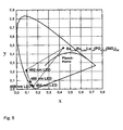
- CIE x and CIE y stand for the coordinates in the CIE standard color diagram familiar to the person skilled in the art (here standard observer 1931), with which the color of a light source is described. All the variables listed above are calculated from emission spectra of the light source according to methods familiar to the person skilled in the art.
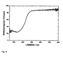
- yellow-orange light such light whose intensity maximum is between 560 and 590 nm wavelength and as red light whose maximum is between 600 and 670 nm wavelength.
- the reaction is usually carried out at a temperature above 800 ° C.
- the reducing conditions are set, for example, with carbon monoxide, forming gas or hydrogen or at least a vacuum or oxygen-deficient atmosphere, preferably produced under carbon monoxide.
- calcination is carried out again at a temperature of> 1000 ° C., preferably between 1100 and 1300 ° C., preferably under forming gas N 2 / H 2 stream and particularly preferably in N 2 / H 2 stream (90-70: 10). 30).
- inorganic or organic substance is a substance from the group of ammonium halides, preferably ammonium chloride, alkaline earth fluorides such as calcium, strontium or barium fluoride, borates, Boric acid, carbonates, preferably ammonium bicarbonate, alcoholates such as oxalates and / or silica such as tetraethyl orthosilicate (TEOS) used.
- ammonium halides preferably ammonium chloride, alkaline earth fluorides such as calcium, strontium or barium fluoride, borates, Boric acid, carbonates, preferably ammonium bicarbonate, alcoholates such as oxalates and / or silica such as tetraethyl orthosilicate (TEOS) used.
- TEOS tetraethyl orthosilicate
- the phosphors according to the invention can be prepared either by a conventional solid-state diffusion method (starting from the oxides, nitrates, carbonates or halides of the corresponding alkaline earth metals, semimetals, metals or rare earths) or wet-chemically from inorganic and / or organic metal and / or rare earth salts by means of sol Gel process, coprecipitation and / or drying process.
- the solid-state diffusion method is preferred.
- chloride solutions of the corresponding phosphorus are mixed with a TEOS / NH 4 HCO 3 solution, whereby forms the phosphor precursor, which is then converted by a single or multi-stage thermal treatment in the phosphor.
- Spray pyrolysis belongs to the aerosol processes which are characterized by spraying solutions, suspensions or dispersions into a reaction chamber (reactor) heated in different ways, as well as the formation and separation of solid particles.
- spray pyrolysis as the high-temperature process is characterized by the thermal decomposition of the educts used (eg salts) and the formation of new substances (eg oxides, mixed oxides ) instead of.
- the yellow-orange-emitting phosphors according to the invention can also be mixed with red-emitting phosphors, resulting in Such mixtures are very well suited for general lighting applications (eg for warm white LEDs) and LCD backlighting.
- a further embodiment of the present invention is therefore a mixture comprising at least one compound of the formula I and at least one red-emitting phosphor, which is preferably selected from Ce-doped garnets, Eu-doped thiogallates, Eu-doped sulfoselenides and / or or Ce-doped nitrides, oxynitrides, Alumonitriden and / or Mn (IV) doped oxides and / or fluorides.
- red-emitting phosphor which is preferably selected from Ce-doped garnets, Eu-doped thiogallates, Eu-doped sulfoselenides and / or or Ce-doped nitrides, oxynitrides, Alumonitriden and / or Mn (IV) doped oxides and / or fluorides.
- the red-emitting phosphor is selected from the nitride phosphors preferably (Ca, Sr, Ba) 2 Si 5 N 8: Eu, (Ca, Sr) AlSiN 3: Eu, (Ca, Sr, Ba ) SiN 2 : Eu, (Ca, Sr, Ba) 6 Si 3 O 6 N 4 : Eu, (A 2-0.5y-x Eu x Si 5 N 8-y O y , wherein A is one or more Elements selected from Ca, Sr, Ba, and x represent a value in the range of 0.005 to 1, and y represents a value in the range of 0.01 to 3, or values of said compounds in which individual lattice positions are governed by other chemical elements , such as alkali metals, aluminum, gallium, or gadolinium, or occupy such other elements as a dopant vacancies known to those skilled and suitable material systems are silicon nitrides and Alumosilikonitride represent (see.
- the compound A 2-0.5y-x Eu x Si 5 N 8-y O y wherein A represents one or more elements selected from Ca, Sr, Ba and x represents a value in the range of 0.005 to 1 and y is a value in the range of 0.01 to 3 is in the patent application EP10000933.1 described and is called in the following compound of formula II. It can the Compound be present as a pure substance or in a mixture with at least one further silicon and oxygen-containing compound, it being preferred if the at least one further silicon and oxygen-containing compound is a reaction by-product of the preparation of the compound of formula II and this the application-relevant optical properties of the compound of formula II is not adversely affected.
- a mixture containing a compound of formula II which is obtainable by a process in which in a step a) suitable starting materials selected from binary nitrides, halides and oxides or corresponding reactive forms are mixed thereto and the mixture in a step b) thermally treated under reductive conditions is another subject of the invention.
- a in preferred embodiments is Sr
- x in preferred embodiments represents a value in the range of 0.01 to 0.8, preferably in the range 0.02 to 0.7, and particularly preferred from the range 0.05 to 0.6 and particularly preferably from the range 0.1 to 0.4
- y in preferred embodiments is for a value from the range of 0.1 to 2.5, preferably from the range 0, 2 to 2, and more preferably from 0.22 to 1.8.
- the reaction is usually carried out at a temperature above 800 ° C, preferably at a temperature above 1200 ° C and more preferably in the range of 1400 ° C -1800 ° C.
- the reductive conditions are eg carbon monoxide, forming gas or hydrogen or at least Adjusted vacuum or oxygen deficiency atmosphere, preferably in a stream of nitrogen, preferably in the N 2 / H 2 stream and particularly preferably in the N 2 / H 2 / NH 3 stream adjusted.
- the compounds of the formula II are to be prepared in pure form, this can be done either by precise control of the educt stoichiometry or by mechanical separation of the crystals of the compounds of the formula II from the glassy fractions.
- the separation can be carried out, for example, via the different density, particle shape or particle size according to separation methods known to the person skilled in the art.
- the compound (or phosphor) according to formula I and the at least one red emitting phosphor are usually present in a weight ratio of 20: 1 to 1: 1. It is preferred according to the invention for the at least one phosphor of the formula I and the at least one red-emitting phosphor to be present in a weight ratio of 10: 1 to 3: 1 and particularly preferably 6: 1 to 4: 1.
- Another subject of the invention is a process for the preparation of a phosphor mixture in which at least one compound (or phosphor) of the formula I is mixed with at least one red-emitting phosphor.
- the particle size of the phosphors according to the invention is usually between 50 nm and 30 .mu.m, preferably between 1 .mu.m and 20 .mu.m.
- the phosphors in particle form have a closed surface coating consisting of SiO 2 , TiO 2 , Al 2 O 3 , ZnO, ZrO 2 and / or Y 2 O 3 or mixed oxides thereof.
- This surface coating has the advantage that an adaptation of the refractive index to the environment can be achieved by a suitable graduation of the refractive indices of the coating materials. In In this case, the scattering of the light at the surface of the phosphor is reduced and a larger proportion of the light can penetrate into the phosphor and be absorbed and converted there.
- the refractive index matched surface coating allows more light to be coupled out of the phosphor because the total internal reflection is reduced.
- a closed layer is advantageous if the phosphor has to be encapsulated. This may be necessary to counter sensitivity of the phosphor or parts thereof to diffusing water or other materials in the immediate environment. Another reason for the encapsulation with a closed shell is a thermal decoupling of the actual phosphor from the heat that arises in the chip. This heat leads to a reduction in the fluorescent light output of the phosphor and may also affect the color of the fluorescent light. Finally, it is possible by such a coating to increase the efficiency of the phosphor by preventing lattice vibrations arising in the phosphor from propagating to the environment.
- the phosphors have a porous surface coating consisting of SiO 2 , TiO 2 , Al 2 O 3 , ZnO, ZrO 2 and / or Y 2 O 3 or mixed oxides thereof or of the phosphor composition.
- porous coatings offer the possibility of further reducing the refractive index of a single layer.
- the preparation of such porous coatings can be accomplished by three conventional methods as described in US Pat WO 03/027015 which is fully incorporated by reference into the context of the present application: the etching of glass (eg soda-lime glasses (see US 4,019,884 )), the application of a porous layer and the combination of porous layer and an etching process.
- the phosphor particles have a surface which carries functional groups which allow a chemical connection to the environment, preferably consisting of epoxy or silicone resin.
- functional groups may e.g. oxo group-attached esters or other derivatives that can form linkages with components of the epoxy-based and / or silicone-based binders.
- Such surfaces have the advantage that a homogeneous mixing of the phosphors is made possible in the binder. Furthermore, the rheological properties of the system phosphor / binder and also the pot life can be adjusted to a certain extent. This simplifies the processing of the mixtures.
- the phosphor layer of the invention applied to the LED chip preferably consists of a mixture of silicone and homogeneous phosphor particles, which is applied by volume casting, and the silicone has a surface tension, this phosphor layer is not uniform at the microscopic level or the thickness of the layer is not consistent constant. This is usually also the case when the phosphor is not applied by the volume casting method, but in the so-called chip-level conversion method in which a highly concentrated, thin phosphor layer is applied directly to the surface of the chip by means of electrostatic methods.
- any external forms of the phosphor particles such as spherical particles, platelets and structured materials and ceramics.
- platelet-shaped phosphors as a further preferred embodiment is done by conventional methods from the corresponding metal and / or rare earth salts.
- the manufacturing process is in EP 763573 and DE 102006054331 described in detail which are fully incorporated by reference into the context of the present application.
- These platelet-shaped phosphors can be prepared by a natural or synthetically produced highly stable support or a substrate of, for example mica, SiO 2 , Al 2 O 3 , ZrO 2 , glass or TiO 2 platelets, which is a very has high aspect ratio, has an atomically smooth surface and an adjustable thickness, can be coated by precipitation reaction in aqueous dispersion or suspension with a phosphor layer.
- the platelets may also consist of the phosphor material itself, or be composed of a material. If the wafer itself merely serves as a carrier for the phosphor coating, it must be made of a material which is transparent to the primary radiation of the LED, or absorbs the primary radiation and transfers this energy to the phosphor layer.
- the platelet-shaped phosphors are dispersed in a resin (eg, silicone or epoxy), and this dispersion is applied to the LED chip.
- the platelet-shaped phosphors can be produced on a large scale in thicknesses of 50 nm up to about 20 ⁇ m, preferably between 150 nm and 5 ⁇ m.
- the diameter is from 50 nm to 20 microns. It usually has an aspect ratio (ratio of diameter to particle thickness) of 1: 1 to 400: 1, and in particular 3: 1 to 100: 1.
- the platelet expansion (length x width) depends on the arrangement. Platelets are also suitable as scattering centers within the conversion layer, especially if they have particularly small dimensions.
- the surface of the platelet-shaped phosphor according to the invention facing the LED chip can be provided with a coating which acts in an anti-reflection manner with respect to the primary radiation emitted by the LED chip.
- This coating can also consist of photonic crystals. This also includes a structuring of the surface of the platelet-shaped phosphor in order to achieve certain functionalities.
- the production of the phosphors according to the invention in the form of ceramic bodies is carried out analogously to that in the DE 102006037730 (Merck), which is fully incorporated by reference into the context of the present application.
- the phosphor is prepared wet-chemically by mixing the corresponding reactants and dopants, then isostatically pressed and applied in the form of a homogeneous thin and non-porous platelets directly on the surface of the chip.
- no location-dependent variation of the excitation and emission of the phosphor takes place, whereby the LED equipped with it emits a homogeneous and color-constant light cone and has a high light output.
- the ceramic phosphor bodies can be produced industrially, for example, as platelets in thicknesses of a few 100 nm up to about 500 ⁇ m.
- the platelet extent (length x width) depends on the arrangement.
- the size of the wafer according to the chip size from about 100 .mu.m * 100 microns to several mm 2 ) with a certain excess of about 10% - 30% of the chip surface with a suitable chip arrangement (eg Flip Chip arrangement) or to choose accordingly. If the phosphor plate is placed over a finished LED, the emerging cone of light is completely covered by the plate.
- the side surfaces of the ceramic phosphor body can be mirrored with a light or noble metal, preferably aluminum or silver.
- the mirroring causes no light to emerge laterally from the phosphor body. Lateral exiting light can reduce the luminous flux to be coupled out of the LED.
- the mirroring of the ceramic phosphor body is carried out in a process step after the isostatic pressing to bars or plates, which may be done before the mirroring a tailor of the rods or plates in the required size.
- the side surfaces are wetted, for example, with a solution of silver nitrate and glucose, and then exposed to an ammonia atmosphere at elevated temperature.
- an ammonia atmosphere at elevated temperature.
- electroless metallization offer, see for example Hollemann-Wiberg, Textbook of Inorganic Chemistry, Walter de Gruyter Verlag or Ullmann's Encyclopedia of Chemical Technology.
- the ceramic phosphor body can If necessary, fix with a water glass solution on the substrate of an LED chip.
- the ceramic phosphor body has a structured (eg pyramidal) surface on the side opposite an LED chip.
- the structured surface on the phosphor body is produced in that in the isostatic pressing, the pressing tool has a structured pressing plate and thereby embossed a structure in the surface. Structured surfaces are desired when thin phosphor bodies or platelets are to be produced.
- the pressing conditions are known to the person skilled in the art (see J. Kriegsmann, Technical Ceramic Materials, Chap. 4, German Economic Service, 1998 ). It is important that 2/3 to 5/6 of the melting temperature of the material to be pressed are used as pressing temperatures.
- the excitability of the phosphors according to the invention also extend over a wide range, ranging from about 410 nm to 530 nm, preferably 430 nm to about 500 nm.
- these phosphors are not only suitable for excitation by violet or blue emitting light sources such as LEDs or conventional discharge lamps (eg based on Hg), but also for light sources such as those which exploit the blue In 3+ line at 451 nm.
- Another object of the present invention is a light source, characterized in that it contains a semiconductor and at least one phosphor according to formula I.
- Another object of the present invention is a light source characterized in that it contains a semiconductor and at least one compound of formula I and at least one red emitting phosphor.
- this lighting unit emits white or emits light with a certain color point (color-on-demand principle).
- This concept is e.g. used to design certain corporate designs, e.g. for illuminated company logos, brands etc.
- the light source is a luminescent arrangement based on ZnO, TCO (transparent conducting oxide), ZnSe or SiC or else an arrangement based on an organic light-emitting layer (OLED).
- ZnO transparent conducting oxide
- ZnSe transparent conducting oxide
- SiC organic light-emitting layer
- the light source is a source which exhibits electroluminescence and / or photoluminescence.
- the light source may also be a plasma or discharge source.
- the phosphors according to the invention can either be dispersed in a resin (for example epoxy or silicone resin) or, with suitable size ratios, be arranged directly on the light source or can be arranged remotely therefrom, depending on the application (the latter arrangement also includes “remote phosphor technology”). with a).
- a resin for example epoxy or silicone resin
- remote phosphor technology the advantages of " Remote phosphor technology "are known to the person skilled in the art and can be found, for example, in the following publication: Japanese Journal of Appl. Phys. Vol. 44, No. 21 (2005) L649-L651 ,
- a lighting unit in particular for the backlight of display devices, which is characterized in that it contains at least one light source described above and corresponding display devices, in particular liquid crystal display device (LC display), with a Backlight, which are characterized in that they contain at least one such lighting unit.
- LC display liquid crystal display device
- CRI values> 85 can only be realized if the yellow-orange phosphor according to the invention according to formula I is additionally combined with red phosphors in the LED.
- the optical coupling of the illumination unit between the phosphor and the semiconductor is realized by a light-conducting arrangement.
- the semiconductor is installed at a central location and this is optically coupled to the phosphor by means of light-conducting devices, such as, for example, photoconductive fibers.
- the lighting requirements adapted lights can only be realized consisting of one or different phosphors, which can be arranged to form a luminescent screen, and a light guide, which is coupled to the light source.
- a strong light source at a convenient location for the electrical installation and to install without further electrical wiring, but only by laying fiber optics at any location lights of phosphors, which are coupled to the light guide.
- Another object of the present invention is the use of the phosphors according to the invention for the partial or complete conversion of blue or in the near UV emission of a light-emitting diode.
- the use of the phosphors according to the invention for the conversion of blue or near-UV emission into visible white radiation is preferred. Furthermore, the use of the phosphors according to the invention for converting the primary radiation into a specific color point according to the "color on demand" concept is preferred.
- Another object of the present invention is the use of the phosphors according to the invention in electroluminescent materials, such as electroluminescent films (also called phosphors or light foils) in which, for example, zinc sulfide or zinc sulfide doped with Mn 2+ , Cu + , or Ag + as an emitter is used, which emit in the yellow-green area.
- electroluminescent materials such as electroluminescent films (also called phosphors or light foils) in which, for example, zinc sulfide or zinc sulfide doped with Mn 2+ , Cu + , or Ag + as an emitter is used, which emit in the yellow-green area.
- the fields of application of the electroluminescent film are, for example, advertising, display backlighting in liquid crystal displays (LC displays) and thin-film transistor displays (TFT displays), self-illuminating license plate labels, floor graphics (in conjunction with a non-slip and non-slip laminate), in display and / or controls for example in automobiles, trains, ships and aircraft or household, gardening, measuring or sports and leisure equipment.
- LC displays liquid crystal displays
- TFT displays thin-film transistor displays
- license plate labels in conjunction with a non-slip and non-slip laminate
- floor graphics in conjunction with a non-slip and non-slip laminate
- H 3 BO 3 0.0687 g (0.195 mmol) Eu 2 O 3 , 1.5900 g (3.996 mmol) Lu 2 O 3 , 1.2899 g (9.778 mmol) (NH 4 ) 2 HPO 4 , 1.8504 g (9.377 mmol) BaCO 3 , 0.2134 g (3.552 mmol ) SiO 2 and 0.02 g (0.323 mmol) of H 3 BO 3 are slurried with acetone and thoroughly mixed in an agate mortar. The powder is dried and calcined for 5 h at 1000 ° C for phase formation in air. It is then heated at 1550 ° C for 10 h under CO, so that the crystallization begins and europium is reduced to the diVAlenten state.
- the powder becomes one again after grinding Calcination, and now for 5 h at 1200 ° C under forming gas N 2 / H 2 (90/10) to completely reduce residual Eu 3+ .
- the resulting sinter cake is ground and sieved through a 36 ⁇ m sieve.
- the phosphor is removed and suspended in 100 ml of 1 molar hydrochloric acid. The resulting suspension is stirred for 3 hours, then the stirrer is switched off. After a few minutes, the supernatant is poured off, the residue remaining is again taken up in demineralized water, filtered off with suction, washed neutral with demineralized water and dried.
- the phosphor is removed and suspended in 100 ml of deionized water. The resulting suspension is stirred for 30 minutes, then the stirrer is switched off. After a few minutes, the supernatant is poured off, the residue remaining is again taken up in demineralized water, filtered off with suction, washed neutral with demineralized water and dried.
- the phosphor is removed and suspended in 100 ml of deionized water. The resulting suspension is stirred for 30 minutes, then the stirrer is switched off. After a few minutes, the supernatant is poured off, the residue remaining is again taken up in demineralized water, filtered off with suction, washed neutral with demineralized water and dried.
- Example 3D Preparation of the phosphor (Sr, Ca) AlSiN 3 : Eu
- Example 4.1 Ba 2.178 Eu 0.022 Lu 1.8 (PO 4 ) 2.2 (SiO 4 ) 0.8 Nitride " 10 g of the phosphor from Example 1 are intimately mixed with 1 g of the phosphor from Example 3C.
- a mixture containing the phosphors of Examples 1 and 3A or 1 and 3B or 1 and 3 D is prepared analogously.
- the phosphor mixture from Example 4.1 is mixed in a tumble mixer with a 2-component silicone (OE 6550 from Dow Corning), so that equal amounts of the phosphor mixture are dispersed in the two components of the silicone; the total concentration of the phosphor mixture in the silicone is 8% by weight.
- OE 6550 from Dow Corning
- CIE x and CIE y represent the coordinates in the CIE standard color diagram familiar to the person skilled in the art (here standard observer 1931), which describes the color of a light source. All the variables listed above are calculated from emission spectra of the light source according to methods familiar to the person skilled in the art.
- the luma equivalency [Im / W] results from the product of the normalized emission spectrum I (lambda) with the eye sensitivity curve V (lambda).
Description
Die Erfindung betrifft Silicophosphat-Verbindungen, Verfahren zur Herstellung dieser Verbindungen und deren Verwendung als Konversionsleuchtstoffe bzw, in Leuchtmitteln.The invention relates to silicophosphate compounds, processes for the preparation of these compounds and their use as conversion phosphors or, in bulbs.
Anorganische Leuchtstoffe werden in Fluoreszenzlichtquellen, emissiven Bildschirmen und als Szintillatorkristalle oder -keramiken für die Konversion von nicht sichtbarer Strahlung oder Hochenergiepartikeln in sichtbares Licht verwendet. Materialklassen, die weite Verbreitung für diese Aufgabe gefunden hat, sind die Ce3+ dotierten Granate, der allgemeinen Zusammensetzung (Y1-w-x-y-zGdxLuyTbz)3(Al1-a-bGaaScb)5O12:Cew, wobei die VAriation der Zusammensetzung zur Optimierung des Spektrums, der Stabilität, der Abklingzeit und/oder zur Umgehung von Patentansprüchen herangezogen werden kann.Inorganic phosphors are used in fluorescent light sources, emissive screens and as scintillator crystals or ceramics for the conversion of non-visible radiation or high energy particles into visible light. Classes of materials which have become widely used for this purpose are the Ce 3+ doped garnets of general composition (Y 1 -xyz Gd x Lu y Tb z ) 3 (Al 1-ab Ga a Sc b ) 5 O 12 : Ce w , wherein the VAriation of the composition for spectrum optimization, stability, the decay time and / or to avoid claims can be used.
Schon 1996, d.h. kurz nach der technischen Realisierung einer blau-emittierenden (In,Ga)N LED mit hoher Energieeffizienz und einem Lichtstrom von mehreren Candela, wurden weiße LEDs durch die teilweise Konversion des blauen Lichts mit eben diesen Granaten realisiert, da die gelb-orange Emissionsfarbe dieser Leuchtstoffe komplementär zur blauen Emissionsfarbe der LED ist und man somit durch additive Farbmischung weißes Licht erhält.Already in 1996, i. Shortly after the technical realization of a blue-emitting (In, Ga) N LED with high energy efficiency and a luminous flux of several candels, white LEDs were realized by the partial conversion of the blue light with these same grenades, because the yellow-orange emission color of these phosphors is complementary to the blue emission color of the LED and thus obtains white light by additive color mixing.
Bis heute enthalten daher viele kommerziell erhältliche weiß-emittierende LEDs einen blau-emittierenden (In,Ga)N Halbleiterchip, der mit einem lumineszierendem Schirm bestehend aus einem keramischen Ce3+ dotierten Granat beschichtet ist.To date, therefore, many commercially available white-emitting LEDs contain a blue-emitting (In, Ga) N semiconductor chip, which is coated with a luminescent screen consisting of a ceramic Ce 3+ doped garnet.
Nichtsdestotrotz geht die Suche nach alternativen gelb-orange emittierenden Konvertermaterialien für Hochleistungs-LEDs unvermindert weiter. Hier stehen zur Zeit vor allem Ce3+ oder Eu2+ dotierte Nitride und Oxynitride im Mittelpunkt des Interesses, da durch die hohe zentroide Verschiebung in diesen Wirtsgittern diese AktiVAtoren Lumineszenz im grünen bis roten Spektralbereich zeigen, während in den meisten rein oxidischen Materialien sowohl Ce3+ als auch Eu2+ vor allem im UV- oder im blauen Spektralbereich lumineszieren.
Leuchtstoffe auf Basis der Eulytine Struktur wurden erstmals von
Phosphors based on the eulytine structure were first reported by
Aufgabe der vorliegenden Erfindung war es, Silicophosphat-Leuchtstoffe zu entwickeln, die eine gelb-orange Lumineszenz aufweisen und sich besonders für den Einsatz in Hochleistungs-pcLEDs zur Erzeugung kaltweißen Lichtes eignen.The object of the present invention was to develop silicophosphate phosphors which have a yellow-orange luminescence and are particularly suitable for use in high-power pcLEDs for producing cold-white light.
Überraschenderweise wurde nun gefunden, dass Eu2+ dotierte Erdalkali-Luthetium-haltige-Silicophosphat-Leuchtstoffe die oben genannte Aufgabe erfüllen. Aufgrund der sehr breiten Fluoreszenzbande und des Farbpunktes sind diese Leuchtstoffe besonders für die Erzeugung von kaltweißen Lichtes geeignet. Sie zeichnen sich gegenüber den bekannten mit Eu3+ oder Ce3+ dotierten Ba2Y2(PO4)2(SiO4) -Leuchtstoffen durch die höhere Absorptionsstärke im blauen Spektralbereich aus.Surprisingly, it has now been found that Eu2 + doped alkaline earth-luthetium-containing silicophosphate phosphors meet the above-mentioned object. Due to the very broad fluorescence band and the color point these phosphors are particularly suitable for the production of cold white light. They are distinguished from the known Ba 2 Y 2 (PO 4 ) 2 (SiO 4 ) phosphors doped with Eu 3+ or Ce 3+ by the higher absorption strength in the blue spectral range.
Eine erste Ausführungsform der vorliegenden Erfindung ist daher eine Verbindung der Formel I,
(Ba1-a-bSraEub)2+x(Lu1-c-d YcGdd)2-x(PO4)2+x(SiO4)1-x (I)
wobei
- b steht für einen Wert aus dem Bereich von 0<bs0,2
- a,c,d stehen unabhängig voneinander für einen Wert aus dem Bereich von 0 bis 1
- x steht für einen Wert aus dem Bereich von 0 bis 0,8.
(Ba 1-ab Sr a Eu b ) 2 + x (Lu 1-cd Y c Gd d ) 2-x (PO 4 ) 2 + x (SiO 4 ) 1-x (I)
in which
- b stands for a value in the range of 0 <bs0,2
- a, c, d independently represent a value in the range of 0 to 1
- x is a value in the range of 0 to 0.8.
Vorzugsweise steht x für einen Wert aus dem Bereich 0,05 bis 0,5 und insbesondere bevorzugt aus dem Bereich 0,1 bis 0,3.
Vorzugsweise steht a für einen Wert aus dem Bereich 0 bis 0,5, insbesondere bevorzugt aus dem Bereich 0 bis 0,2.
Vorzugsweise steht b für einen Wert aus dem Bereich 0<b<0,1. Vorzugsweise stehen c und d unabhängig voneinander für einen Wert aus dem Bereich von 0 bis 0,8.Preferably, x is a value in the range 0.05 to 0.5 and particularly preferably in the range 0.1 to 0.3.
Preferably, a is a value from the range 0 to 0.5, particularly preferably from the range 0 to 0.2.
Preferably, b stands for a value from the range 0 <b <0.1. Preferably, c and d independently represent a value in the range of 0 to 0.8.
Im Folgenden werden die erfindungsgemäßen Verbindungen der Formel I bzw. die Mischungen o.g. erfindungsgemäßen Mischungen gemeinsam auch vereinfacht als Leuchtstoffe bezeichnet.In the following, the compounds of the formula I or the mixtures according to the invention o.g. mixtures according to the invention also referred to collectively as phosphors.
Erfindungsgemäße Leuchtstoffe in geringen Mengen eingesetzt ergeben bereits gute LED-Qualitäten. Die LED-Qualität wird dabei über übliche Parameter, wie beispielsweise den Color Rendering Index oder den Farbpunkt in CIE x und CIE y Koordinaten beschrieben.Inventive phosphors used in small quantities already give good LED qualities. The LED quality is described using common parameters, such as the Color Rendering Index or the color point in CIE x and CIE y coordinates.
Der Color Rendering Index oder CRI ist eine dem Fachmann geläufige, einheitslose lichttechnische Größe, welche die Farbwiedergabetreue einer künstlichen Lichtquelle mit derjenigen des Sonnenlichtes bzw. Filamentlichtquellen vergleicht (die beiden letztgenannten besitzen einen CRI von 100).The Color Rendering Index, or CRI, is a unitary photometric quantity known to those skilled in the art that compares the color fidelity of an artificial light source to that of sunlight or filament light sources (the latter two have a CRI of 100).
CIE x und CIE y stehen für die Koordinaten im dem dem Fachmann geläufigen CIE Normfarbdiagramm (hier Normalbeobachter 1931), mit denen die Farbe einer Lichtquelle beschrieben wird.
Alle oben aufgeführten Größen werden nach dem Fachmann geläufigen Methoden aus Emissionsspektren der Lichtquelle berechnet.CIE x and CIE y stand for the coordinates in the CIE standard color diagram familiar to the person skilled in the art (here standard observer 1931), with which the color of a light source is described.
All the variables listed above are calculated from emission spectra of the light source according to methods familiar to the person skilled in the art.
Im Kontext dieser Anmeldung wird als gelb-orange Licht solches Licht bezeichnet, dessen Intensitätsmaximum zwischen 560 und 590 nm Wellenlänge liegt und als rotes Licht, dessen Maximum zwischen 600 und 670 nm Wellenlänge liegt.In the context of this application is referred to as yellow-orange light such light whose intensity maximum is between 560 and 590 nm wavelength and as red light whose maximum is between 600 and 670 nm wavelength.
Ein weiterer Erfindungsgegenstand ist ein Verfahren zur Herstellung einer Verbindung der Formel I umfassend folgende Schritte:
- a) Mischen von Lutetium-, Europium-, Silicium-, Barium-, Strontium-, Yttrium-, Gadolinium- und/oder Phosphat-haltigen Materialien
- b) Zugabe mindestens eines weiteren anorganischen und/oder organischen Stoffes
- c) thermische Behandlung der Mischung.
- a) mixing of lutetium, europium, silicon, barium, strontium, yttrium, gadolinium and / or phosphate-containing materials
- b) adding at least one further inorganic and / or organic substance
- c) thermal treatment of the mixture.
Bei der oben genannten thermischen Behandlung ist es bevorzugt, wenn diese zumindest teilweise unter reduzierenden Bedingungen durchgeführt wird. Im Schritt c) erfolgt die Umsetzung üblicherweise bei einer Temperatur oberhalb 800 °C. Vorzugsweise erfolgt die thermische Behandlung in einem Mehrstufenprozess, besonders bevorzugt 3-Stufig, d.h. zuerst wird bei einer Temperatur > 900 °C unter Luft kalziniert und anschließend vorzugsweise bei einer Temperatur oberhalb 1400°C, besonders bevorzugt bei T = 1500 bis 1700 °C unter reduzierenden Bedingungen geheizt. Die reduzierenden Bedingungen werden dabei z.B. mit Kohlenmonoxid, Formiergas oder Wasserstoff oder zumindest VAkuum oder Sauerstoffmangel-Atmosphäre eingestellt, bevorzugt unter Kohlenmonoxid erzeugt. Nach dem Vermahlen wird erneut bei einer Temperatur > 1000 °C, vorzugsweise zwischen 1100 und 1300°C kalziniert, vorzugsweise unter Formiergas N2/H2-Strom und insbesondere bevorzugt im N2/H2 -Strom (90 - 70 : 10 - 30).In the above-mentioned thermal treatment, it is preferable that this is carried out at least partially under reducing conditions. In step c), the reaction is usually carried out at a temperature above 800 ° C. Preferably, the thermal treatment is carried out in a multi-stage process, more preferably 3 stages, ie first calcined at a temperature> 900 ° C under air and then preferably at a temperature above 1400 ° C, more preferably at T = 1500 to 1700 ° C below heated reducing conditions. The reducing conditions are set, for example, with carbon monoxide, forming gas or hydrogen or at least a vacuum or oxygen-deficient atmosphere, preferably produced under carbon monoxide. After grinding, calcination is carried out again at a temperature of> 1000 ° C., preferably between 1100 and 1300 ° C., preferably under forming gas N 2 / H 2 stream and particularly preferably in N 2 / H 2 stream (90-70: 10). 30).
Als anorganischen oder organischen Stoff (im Schritt b) wird ein Stoff aus der Gruppe der Ammoniumhalogenide, vorzugsweise Ammoniumchlorid, Erdalkalifluoride wie Calcium-, Strontium- oder Bariumfluorid, Borate, Borsäure, Carbonate, vorzugsweise Ammoniumhydrogencarbonat, Alkoholate wie Oxalate und/oder Kieselsäure wie Tetraethylorthosilikat (TEOS) eingesetzt.
Die Herstellung der erfindungsgemäßen Leuchtstoffe kann entweder über eine herkömmliche Festkörperdiffusionsmethode (ausgehend von den Oxiden, Nitraten, Carbonaten oder Halogeniden der entsprechenden Erdalkalimetalle, Halbmetalle, Metalle oder Seltenerden) oder nasschemisch aus anorganischen und/oder organischen Metall- und/oder Seltenerd-Salzen mittels Sol-Gel-Verfahren, Copräzipitations- und /oder Trocknungsverfahren erfolgen. Bevorzugt ist erfindungsgemäß die Festkörperdiffusionsmethode.As inorganic or organic substance (in step b) is a substance from the group of ammonium halides, preferably ammonium chloride, alkaline earth fluorides such as calcium, strontium or barium fluoride, borates, Boric acid, carbonates, preferably ammonium bicarbonate, alcoholates such as oxalates and / or silica such as tetraethyl orthosilicate (TEOS) used.
The phosphors according to the invention can be prepared either by a conventional solid-state diffusion method (starting from the oxides, nitrates, carbonates or halides of the corresponding alkaline earth metals, semimetals, metals or rare earths) or wet-chemically from inorganic and / or organic metal and / or rare earth salts by means of sol Gel process, coprecipitation and / or drying process. According to the invention, the solid-state diffusion method is preferred.
Bei den nasschemischen Verfahren über wässrige Vorstufen (Precursoren) der Leuchtstoffe sind folgende Methoden bekannt:
- Cofällung (auch Copräzipitation genannt) mit einer NH4HCO3-Lösung (siehe z.B.
Jander, Blasius Lehrbuch der analyt. u. präp. anorg. Chem. 2002 - Pecchini-Verfahren mit einer Lösung aus Zitronensäure und Ethylenglykol (siehe z.B.
Annual Review of Materials Research Vol. 36: 2006, 281-331 - Combustion-Verfahren unter Verwendung von Harnstoff
- Sprühtrocknung wässriger oder organischer Salzlösungen (Edukte)
- Sprühpyrolyse (auch Spraypyrolyse genannt) wässriger oder organischer Salzlösungen (Edukte)
- Eindampfen von Nitratlösungen und thermischer Umsetzung des Rückstandes
- Co-precipitation (also called coprecipitation) with an NH 4 HCO 3 solution (see, for example , US Pat
Jander, Blasius textbook of the analyt. u. prep. anorg. Chem. 2002 - Pecchini method with a solution of citric acid and ethylene glycol (see, eg
Annual Review of Materials Research Vol. 36: 2006, 281-331 - Combustion process using urea
- Spray drying of aqueous or organic salt solutions (educts)
- Spray pyrolysis (also called spray pyrolysis) of aqueous or organic salt solutions (educts)
- Evaporation of nitrate solutions and thermal reaction of the residue
Bei der o.g. Cofällung werden z.B. Chloridlösungen der entsprechenden Leuchtstoffedukte mit einer TEOS/NH4HCO3-Lösung versetzt, wodurch sich der Leuchtstoffprecursor bildet, der anschließend durch eine ein- oder mehrstufige thermische Behandlung in den Leuchtstoff umgewandelt wird.In the above-mentioned co-precipitation, for example, chloride solutions of the corresponding phosphorus are mixed with a TEOS / NH 4 HCO 3 solution, whereby forms the phosphor precursor, which is then converted by a single or multi-stage thermal treatment in the phosphor.
Beim Pecchini-Verfahren werden z.B. Nitratlösungen der entsprechenden Leuchtstoffedukte bei Raumtemperatur mit einem Fällungsreagenz bestehend aus Zitronensäure und Ethylenglykol versetzt und anschließend erhitzt. Durch Erhöhung der Viskosität kommt es zur Leuchtstoffprecursor-Bildung.In the pecchini method, e.g. Nitrate solutions of the corresponding Leuchtstoffedukte at room temperature with a precipitating agent consisting of citric acid and ethylene glycol added and then heated. Increasing the viscosity causes phosphor precursor formation.
Beim bekannten Combustion-Verfahren werden z.B. Nitratlösungen der entsprechenden Edukte in Wasser gelöst, dann unter Rückfluss gekocht und mit Harnstoff versetzt, wodurch sich der Leuchtstoffprecursor langsam bildet.In the known combustion method, e.g. Dissolved nitrate solutions of the corresponding starting materials in water, then boiled under reflux and mixed with urea, whereby the phosphor precursor is formed slowly.
Die Sprühpyrolyse gehört zu den Aerosolverfahren, die durch Versprühen von Lösungen, Suspensionen oder Dispersionen in einen durch unterschiedliche Art und Weise erhitzten Reaktionsraum (Reaktor) sowie die Bildung und Abscheidung von Feststoff- Partikeln gekennzeichnet sind. Im Gegensatz zur Sprühtrocknung mit Heißgastemperaturen < 200°C finden bei der Sprühpyrolyse als Hochtemperatur-Prozess außer der Verdampfung des Lösungsmittels zusätzlich die thermische Zersetzung der verwendeten Edukte (z. B. Salze) sowie die Neubildung von Stoffen (z. B. Oxide, Mischoxide) statt.Spray pyrolysis belongs to the aerosol processes which are characterized by spraying solutions, suspensions or dispersions into a reaction chamber (reactor) heated in different ways, as well as the formation and separation of solid particles. In contrast to spray drying with hot gas temperatures <200 ° C, spray pyrolysis as the high-temperature process is characterized by the thermal decomposition of the educts used (eg salts) and the formation of new substances (eg oxides, mixed oxides ) instead of.
Die o.g. 6 VerfahrensVArianten sind ausführlich in der
Die erfindungsgemäßen gelb-orange-emittierenden Leuchtstoffe können auch mit rot-emittierenden Leuchtstoffen gemischt werden, wodurch sich solche Mischungen sehr gut für Anwendungen in der Allgemeinbeleuchtung (z.B. für warm-weiße LEDs) und LCD-backlighting eignen.The yellow-orange-emitting phosphors according to the invention can also be mixed with red-emitting phosphors, resulting in Such mixtures are very well suited for general lighting applications (eg for warm white LEDs) and LCD backlighting.
Eine weitere Ausführungsform der vorliegenden Erfindung ist daher eine Mischung enthaltend mindestens eine Verbindung der Formel I und mindestens einen rot-emittierenden Leuchtstoff, wobei dieser vorzugsweise ausgewählt wird aus Ce-dotierten Granaten, Eu-dotierten Thiogallaten, Eu-dotierten Sulfoseleniden und Eu- und/oder Ce-dotierten Nitriden, Oxynitriden, Alumonitriden und/oder Mn(IV) dotierten Oxiden und/oder Fluoriden. Dabei kann es insbesondere bevorzugt sein, wenn der rotemittierende Leuchtstoff ausgewählt ist aus den nitridischen Leuchtstoffen, vorzugsweise (Ca,Sr,Ba)2Si5N8:Eu, (Ca,Sr)AlSiN3:Eu, (Ca,Sr;Ba)SiN2:Eu, (Ca,Sr,Ba)6Si3O6N4: Eu, (A2-0,5y-x Eux Si5 N8-y Oy, wobei A steht für ein oder mehrere Elemente ausgewählt aus Ca, Sr, Ba und x steht für einen Wert aus dem Bereich von 0,005 bis 1 und y steht für einen Wert aus dem Bereich von 0,01 bis 3 oder VArianten der genannten Verbindungen, bei denen einzelne Gitterpositionen durch andere chemische Elemente, wie Alkalimetalle, Aluminium, Gallium, oder Gadolinium, substituiert sind bzw. solche weiteren Elemente als Dotierstoff Fehlstellen besetzen. Dem Fachmann bekannte und geeignete Materialsysteme stellen Siliconitride und Alumosilikonitride dar (vgl.
Die Verbindung A2-0,5y-x Eux Si5 N8-y Oy, wobei A steht für ein oder mehrere Elemente ausgewählt aus Ca, Sr, Ba und x steht für einen Wert aus dem Bereich von 0,005 bis 1 und y steht für einen Wert aus dem Bereich von 0,01 bis 3 ist in der Patentanmeldung
In den erfindungsgemäßen Verbindungen der Formel II steht A in bevorzugten Ausführungsformen für Sr, während x in bevorzugten Ausführungsformen steht für einen Wert aus dem Bereich von 0,01 bis 0,8, vorzugsweise aus dem Bereich 0,02 bis 0,7 und insbesondere bevorzugt aus dem Bereich 0,05 bis 0,6 und insbesondere bevorzugt aus dem Bereich 0,1 bis 0,4 und y in bevorzugten Ausführungsformen steht für einen Wert aus dem Bereich von 0,1 bis 2,5, vorzugsweise aus dem Bereich 0,2 bis 2 und insbesondere bevorzugt aus dem Bereich 0,22 bis 1,8.
Zur Herstellung von Leuchtstoffen der Formel II werden in einem Schritt a) geeignete Edukte ausgewählt aus binären Nitriden, Halogeniden und Oxiden oder entsprechenden reaktiven Formen dazu gemischt und das Gemisch in einem Schritt b) unter reduktiven Bedingungen thermisch behandelt. Bei der oben genannten thermischen Behandlung ist es bevorzugt, wenn diese zumindest teilweise unter reduzierenden Bedingungen durchgeführt wird. Im Schritt b) erfolgt die Umsetzung üblicherweise bei einer Temperatur oberhalb 800°C, vorzugsweise bei einer Temperatur oberhalb 1200°C und insbesondere bevorzugt im Bereich von 1400°C -1800°C. Die reduktiven Bedingungen werden dabei z.B. mit Kohlenmonoxid, Formiergas oder Wasserstoff oder zumindest VAkuum oder Sauerstoffmangel-Atmosphäre eingestellt, bevorzugt im Stickstoffstrom, vorzugsweise im N2/H2 -Strom und insbesondere bevorzugt im N2/H2/NH3-Strom eingestellt. Soll die Verbindungen der Formel II rein hergestellt werden, so kann dies entweder über genaue Kontrolle der Eduktstöchiometrie oder durch mechanisches Abtrennen der Kristalle der Verbindungen der Formel II von den glasartigen Anteilen erfolgen. Die Abtrennung kann beispielsweise über die unterschiedliche Dichte, Partikelform oder Partikelgröße nach dem Fachmann bekannten Trennmethoden erfolgen.The compound A 2-0.5y-x Eu x Si 5 N 8-y O y , wherein A represents one or more elements selected from Ca, Sr, Ba and x represents a value in the range of 0.005 to 1 and y is a value in the range of 0.01 to 3 is in the patent application
In the compounds of the formula II according to the invention A in preferred embodiments is Sr, while x in preferred embodiments represents a value in the range of 0.01 to 0.8, preferably in the range 0.02 to 0.7, and particularly preferred from the range 0.05 to 0.6 and particularly preferably from the range 0.1 to 0.4 and y in preferred embodiments is for a value from the range of 0.1 to 2.5, preferably from the
For the preparation of phosphors of the formula II, suitable starting materials selected from binary nitrides, halides and oxides or corresponding reactive forms are mixed in step a) and the mixture is thermally treated in a step b) under reductive conditions. In the above-mentioned thermal treatment, it is preferable that this is carried out at least partially under reducing conditions. In step b), the reaction is usually carried out at a temperature above 800 ° C, preferably at a temperature above 1200 ° C and more preferably in the range of 1400 ° C -1800 ° C. The reductive conditions are eg carbon monoxide, forming gas or hydrogen or at least Adjusted vacuum or oxygen deficiency atmosphere, preferably in a stream of nitrogen, preferably in the N 2 / H 2 stream and particularly preferably in the N 2 / H 2 / NH 3 stream adjusted. If the compounds of the formula II are to be prepared in pure form, this can be done either by precise control of the educt stoichiometry or by mechanical separation of the crystals of the compounds of the formula II from the glassy fractions. The separation can be carried out, for example, via the different density, particle shape or particle size according to separation methods known to the person skilled in the art.
Dabei liegen erfindungsgemäß die Verbindung (bzw. Leuchtstoff) gemäß Formel I und der mindestens eine rot emittierende Leuchtstoff üblicherweise im Gewichtsverhältnis 20:1 bis 1:1 vor. Erfindungsgemäß bevorzugt ist es, wenn der mindestens eine Leuchtstoff der Formel I und der mindestens eine rot emittierende Leuchtstoff im Gewichtsverhältnis 10:1 bis 3:1 und insbesondere bevorzugt 6:1 bis 4:1 vorliegen.According to the invention, the compound (or phosphor) according to formula I and the at least one red emitting phosphor are usually present in a weight ratio of 20: 1 to 1: 1. It is preferred according to the invention for the at least one phosphor of the formula I and the at least one red-emitting phosphor to be present in a weight ratio of 10: 1 to 3: 1 and particularly preferably 6: 1 to 4: 1.
Ein weiterer Erfindungsgegenstand ist ein Verfahren zur Herstellung einer Leuchtstoffmischung bei dem mindestens eine Verbindung (bzw. Leuchtstoff) der Formel I mit mindestens einem rot emittierenden Leuchtstoff gemischt wird.Another subject of the invention is a process for the preparation of a phosphor mixture in which at least one compound (or phosphor) of the formula I is mixed with at least one red-emitting phosphor.
Die Partikelgröße der erfindungsgemäßen Leuchtstoffe beträgt üblicherweise zwischen 50 nm und 30 µm, vorzugsweise zwischen 1 µm und 20 µm.The particle size of the phosphors according to the invention is usually between 50 nm and 30 .mu.m, preferably between 1 .mu.m and 20 .mu.m.
In einer weiteren bevorzugten Ausführungsform besitzen die Leuchtstoffe in Partikelform eine geschlossene Oberflächenbeschichtung, die aus SiO2, TiO2, Al2O3, ZnO, ZrO2 und/oder Y2O3 oder Mischoxide daraus besteht. Diese Oberflächenbeschichtung hat den Vorteil, dass durch eine geeignete Abstufung der Brechungsindices der Beschichtungsmaterialien eine Anpassung des Brechungsindex mit der Umgebung erzielt werden kann. In diesem Fall wird die Streuung des Lichtes an der Oberfläche des Leuchtstoffes verringert und ein größerer Anteil des Lichtes kann in den Leuchtstoff eindringen und dort absorbiert und konvertiert werden. Außerdem ermöglicht es die Brechungsindex-angepasste Oberflächebeschichtung, dass mehr Licht aus dem Leuchtstoff ausgekoppelt wird, weil die interne Totalreflexion verringert wird.In a further preferred embodiment, the phosphors in particle form have a closed surface coating consisting of SiO 2 , TiO 2 , Al 2 O 3 , ZnO, ZrO 2 and / or Y 2 O 3 or mixed oxides thereof. This surface coating has the advantage that an adaptation of the refractive index to the environment can be achieved by a suitable graduation of the refractive indices of the coating materials. In In this case, the scattering of the light at the surface of the phosphor is reduced and a larger proportion of the light can penetrate into the phosphor and be absorbed and converted there. In addition, the refractive index matched surface coating allows more light to be coupled out of the phosphor because the total internal reflection is reduced.
Zudem ist eine geschlossene Schicht dann vorteilhaft, wenn der Leuchtstoff verkapselt werden muss. Dies kann erforderlich sein, um einer Empfindlichkeit des Leuchtstoffes oder Teilen davon gegen diffundierendes Wasser oder andere Materialien in der unmittelbaren Umgebung zu entgegnen. Ein weiterer Grund für die Verkapselung mit einer geschlossenen Hülle ist eine thermische Entkoppelung des eigentlichen Leuchtstoffes von der Wärme, die im Chip entsteht. Diese Wärme führt zu einer Verringerung der Fluoreszenzlichtausbeute des Leuchtstoffes und kann auch die Farbe des Fluoreszenzlichts beeinflussen. Schließlich ist es möglich durch eine solche Beschichtung die Effizienz des Leuchtstoffes zu erhöhen, indem im Leuchtstoff entstehende Gitterschwingungen in ihrer Ausbreitung an die Umgebung gehindert werden.In addition, a closed layer is advantageous if the phosphor has to be encapsulated. This may be necessary to counter sensitivity of the phosphor or parts thereof to diffusing water or other materials in the immediate environment. Another reason for the encapsulation with a closed shell is a thermal decoupling of the actual phosphor from the heat that arises in the chip. This heat leads to a reduction in the fluorescent light output of the phosphor and may also affect the color of the fluorescent light. Finally, it is possible by such a coating to increase the efficiency of the phosphor by preventing lattice vibrations arising in the phosphor from propagating to the environment.
Außerdem bevorzugt ist es, wenn die Leuchtstoffe eine poröse Oberflächenbeschichtung besitzen, die aus SiO2, TiO2, Al2O3, ZnO, ZrO2 und/oder Y2O3 oder Mischoxide daraus oder aus der Leuchtstoffzusammensetzung besteht. Diese porösen Beschichtungen bieten die Möglichkeit, den Brechungsindex einer Einfachschicht weiter zu reduzieren. Die Herstellung solcher poröser Beschichtungen kann nach drei herkömmlichen Methoden geschehen, wie sie in
In einer weiteren bevorzugten Ausführungsform besitzen die Leuchtstoffpartikel eine Oberfläche, die funktionelle Gruppen trägt, welche eine chemische Anbindung an die Umgebung, vorzugsweise bestehend aus Epoxy- oder Silikonharz ermöglicht. Diese funktionellen Gruppen können z.B. über Oxogruppen angebundene Ester oder andere DeriVAte sein, die mit Bestandteilen der Bindemittel auf Basis von Epoxiden und / oder Silikonen Verknüpfungen eingehen können. Solche Oberflächen haben den Vorteil, dass eine homogene Einmischung der Leuchtstoffe in das Bindemittel ermöglicht wird. Des Weiteren können dadurch die rheologischen Eigenschaften des Systems Leuchtstoff / Bindemittel und auch die Topfzeiten in einem gewissen Masse eingestellt werden. Damit wird die Verarbeitung der Gemische vereinfacht.In a further preferred embodiment, the phosphor particles have a surface which carries functional groups which allow a chemical connection to the environment, preferably consisting of epoxy or silicone resin. These functional groups may e.g. oxo group-attached esters or other derivatives that can form linkages with components of the epoxy-based and / or silicone-based binders. Such surfaces have the advantage that a homogeneous mixing of the phosphors is made possible in the binder. Furthermore, the rheological properties of the system phosphor / binder and also the pot life can be adjusted to a certain extent. This simplifies the processing of the mixtures.
Da die auf dem LED Chip aufgebrachte erfindungsgemäße Leuchtstoffschicht vorzugsweise aus einem Gemisch von Silikon und homogenen Leuchtstoffpartikeln besteht, welches im Volumenguss aufgebracht wird, und das Silikon eine Oberflächenspannung aufweist, ist diese Leuchtstoffschicht auf mikroskopischer Ebene nicht einheitlich bzw. ist die Dicke der Schicht nicht durchweg konstant. Dies ist in der Regel auch der Fall wenn der Leuchtstoff nicht nach dem Volumengussverfahren, sondern im sogenannten Chip-Level-Konversionsverfahren, bei dem eine hochkonzentrierte, dünne Leuchtstoffschicht mit Hilfe von elektrostatischen Methoden direkt auf die Oberfläche des Chips appliziert wird, aufgebracht wird.Since the phosphor layer of the invention applied to the LED chip preferably consists of a mixture of silicone and homogeneous phosphor particles, which is applied by volume casting, and the silicone has a surface tension, this phosphor layer is not uniform at the microscopic level or the thickness of the layer is not consistent constant. This is usually also the case when the phosphor is not applied by the volume casting method, but in the so-called chip-level conversion method in which a highly concentrated, thin phosphor layer is applied directly to the surface of the chip by means of electrostatic methods.
Mit Hilfe des oben genannten Verfahrens können beliebige äußere Formen der Leuchtstoffpartikel hergestellt werden, wie sphärische Partikel, Plättchen und strukturierte Materialien und Keramiken.With the aid of the abovementioned method, it is possible to produce any external forms of the phosphor particles, such as spherical particles, platelets and structured materials and ceramics.
Die Herstellung von plättchenförmigen Leuchtstoffen als weitere bevorzugte Ausführungsform geschieht nach herkömmlichen Verfahren aus den entsprechenden Metall- und/oder Seltenerd-Salzen. Das Herstellverfahren ist in
Die plättchenförmigen Leuchtstoffe können in Dicken von 50 nm bis zu etwa 20 µm, vorzugsweise zwischen 150 nm und 5 µm, grosstechnisch hergestellt werden. Der Durchmesser beträgt dabei von 50 nm bis 20 µm. Er besitzt in der Regel ein Aspektverhältnis (Verhältnis des Durchmessers zur Teilchendicke) von 1: 1 bis 400 : 1, und insbesondere 3 : 1 bis 100 : 1. Die Plättchenausdehnung (Länge x Breite) ist von der Anordnung abhängig. Plättchen eignen sich auch als Streuzentren innerhalb der Konversionsschicht, insbesondere dann, wenn sie besonders kleine Abmessungen aufweisen.
Die dem LED Chip zugewandte Oberfläche des erfindungsgemäßen plättchenförmigen Leuchtstoffes kann mit einer Beschichtung versehen werden, welche entspiegelnd in Bezug auf die von dem LED Chip emittierte Primärstrahlung wirkt. Dies führt zu einer Verringerung der Rückstreuung der Primärstrahlung, wodurch diese besser in den erfindungsgemäßen Leuchtstoffkörper eingekoppelt werden kann.
Hierfür eignen sich beispielsweise brechzahlangepasste Beschichtungen, die eine folgende Dicke d aufweisen müssen: d = [Wellenlänge der Primärstrahlung des LED Chips /(4* Brechzahl der Leuchtstoffkeramik)], s. beispielsweise Gerthsen, Physik, Springer Verlag, 18. Auflage, 1995. Diese Beschichtung kann auch aus photonischen Kristallen bestehen. Wobei hierunter auch eine Strukturierung der Oberfläche des plättchenförmigen Leuchtstoffes fällt, um bestimmte Funktionalitäten zu erreichen.The production of platelet-shaped phosphors as a further preferred embodiment is done by conventional methods from the corresponding metal and / or rare earth salts. The manufacturing process is in
The platelet-shaped phosphors can be produced on a large scale in thicknesses of 50 nm up to about 20 μm, preferably between 150 nm and 5 μm. The diameter is from 50 nm to 20 microns. It usually has an aspect ratio (ratio of diameter to particle thickness) of 1: 1 to 400: 1, and in particular 3: 1 to 100: 1. The platelet expansion (length x width) depends on the arrangement. Platelets are also suitable as scattering centers within the conversion layer, especially if they have particularly small dimensions.
The surface of the platelet-shaped phosphor according to the invention facing the LED chip can be provided with a coating which acts in an anti-reflection manner with respect to the primary radiation emitted by the LED chip. This leads to a reduction in backscatter the primary radiation, whereby it can be better coupled into the phosphor body according to the invention.
For example, refractive index-adapted coatings, which must have a following thickness d, are suitable for this: d = [wavelength of the primary radiation of the LED chip / (4 * refractive index of the phosphor ceramic)], see FIG. for example, Gerthsen, Physik, Springer Verlag, 18th edition, 1995. This coating can also consist of photonic crystals. This also includes a structuring of the surface of the platelet-shaped phosphor in order to achieve certain functionalities.
Die Herstellung der erfindungsgemäßen Leuchtstoffe in Form von keramischen Körpern erfolgt analog nach dem in der
Die Seitenflächen des keramischen Leuchtstoffkörpers können mit einem Leicht- oder Edelmetall, vorzugsweise Aluminium oder Silber verspiegelt werden. Die Verspiegelung bewirkt, dass kein Licht lateral aus dem Leuchtstoffkörper austritt. Lateral austretendes Licht kann den aus der LED auszukoppelnden Lichtstrom verringern. Die Verspiegelung des keramischen Leuchtstoffkörpers erfolgt in einem Prozessschritt nach der isostatischen Verpressung zu Stangen oder Plättchen, wobei vor der Verspiegelung eventuell ein Schneider der Stangen oder Plättchen in die erforderliche Größe erfolgen kann. Die Seitenflächen werden hierzu z.B. mit einer Lösung aus Silbernitrat und Glucose benetzt und anschließend bei erhöhter Temperatur einer Ammoniak-Atmosphäre ausgesetzt. Hierbei bildet sich z.B. ein silberner Belag auf den Seitenflächen aus.
Alternativ bieten sich auch stromlose Metallisierungsverfahren an, siehe beispielsweise
Alternatively, also electroless metallization offer, see for example
In einer weiteren Ausführungsform besitzt der keramische Leuchtstoffkörper auf der, einem LED Chip entgegengesetzten Seite eine strukturierte (z.B. pyramidale) Oberfläche. Somit kann möglichst viel Licht aus dem Leuchtstoffkörper ausgekoppelt werden. Die strukturierte Oberfläche auf dem Leuchtstoffkörper wird dadurch hergestellt, in dem beim isostatischen Verpressen das Presswerkzeug eine strukturierte Pressplatte aufweist und dadurch eine Struktur in die Oberfläche prägt. Strukturierte Oberflächen sind dann gewünscht, wenn möglichst dünne Leuchtstoffkörper bzw. Plättchen hergestellt werden sollen. Die Pressbedingungen sind dem Fachmann bekannt (siehe
Die Anregbarkeit der erfindungsgemäßen Leuchtstoffe erstrecken sich zudem über einen weiten Bereich, der von etwa 410 nm bis 530 nm, bevorzugt 430 nm bis zu etwa 500 nm reicht. Damit sind diese Leuchtstoffe nicht nur zur Anregung durch violett oder blau emittierende Lichtquellen wie LEDs oder konventionelle Entladungslampen (z.B. auf Hg-Basis) geeignet, sondern auch für Lichtquellen wie solche, welche die blaue In3+ -Linie bei 451 nm ausnutzen.The excitability of the phosphors according to the invention also extend over a wide range, ranging from about 410 nm to 530 nm, preferably 430 nm to about 500 nm. Thus, these phosphors are not only suitable for excitation by violet or blue emitting light sources such as LEDs or conventional discharge lamps (eg based on Hg), but also for light sources such as those which exploit the blue In 3+ line at 451 nm.
Ein weiterer Gegenstand der vorliegenden Erfindung ist eine Lichtquelle, dadurch gekennzeichnet, dass diese einen Halbleiter und mindestens einen Leuchtstoff nach Formel I enthält.Another object of the present invention is a light source, characterized in that it contains a semiconductor and at least one phosphor according to formula I.
Ein weiterer Gegenstand der vorliegenden Erfindung ist eine Lichtquelle dadurch gekennzeichnet, dass diese einen Halbleiter und mindestens eine Verbindung nach Formel I sowie mindestens einen rot emittierenden Leuchtstoff enthält. Vorzugsweise ist diese Beleuchtungseinheit weiß emittierend oder emittiert Licht mit einem bestimmten Farbpunkt (Color-on-demand-Prinzip).Another object of the present invention is a light source characterized in that it contains a semiconductor and at least one compound of formula I and at least one red emitting phosphor. Preferably, this lighting unit emits white or emits light with a certain color point (color-on-demand principle).
Unter dem color-on-demand Konzept versteht man die Realisierung von Licht eines bestimmten Farbpunktes mit einer pcLED (= phosphor converted LED) unter Einsatz eines oder mehrer Leuchtstoffe. Dieses Konzept wird z.B. verwendet, um bestimmte Corporate Designs, z.B. für beleuchtete Firmenlogos, Marken etc. zu erzeugen.The color-on-demand concept is the realization of light of a certain color point with a pcLED (= phosphor converted LED) using one or more phosphors. This concept is e.g. used to design certain corporate designs, e.g. for illuminated company logos, brands etc.
In einer bevorzugten Ausführungsform der erfindungsgemäßen Lichtquelle handelt es sich bei dem Halbleiter um ein lumineszentes IndiumAluminiumGalliumNitrid, insbesondere der Formel In;GajAlkN, wobei 0 ≤ i, 0 ≤ j, 0 ≤ k, und i+j+k=1 ist.In a preferred embodiment, the light source of the invention is, in the semiconductor is a luminescent indium aluminum gallium nitride, in particular of the formula In, Ga j Al k N, where 0 ≤ i, 0 ≤ j, 0 ≤ k, and i + j + k = 1 is.
In einer weiteren bevorzugten Ausführungsform der erfindungsgemäßen Lichtquelle handelt es sich bei der Lichtquelle um eine lumineszente auf ZnO, TCO (Transparent conducting oxide), ZnSe oder SiC basierende Anordnung oder auch um eine auf einer organischen lichtemittierende Schicht basierende Anordnung (OLED).In a further preferred embodiment of the light source according to the invention, the light source is a luminescent arrangement based on ZnO, TCO (transparent conducting oxide), ZnSe or SiC or else an arrangement based on an organic light-emitting layer (OLED).
In einer weiteren bevorzugten Ausführungsform der erfindungsgemäßen Lichtquelle handelt es sich bei der Lichtquelle um eine Quelle, die Elektrolumineszenz und/oder Photolumineszenz zeigt. Weiterhin kann es sich bei der Lichtquelle auch um eine Plasma- oder Entladungsquelle handeln.In a further preferred embodiment of the light source according to the invention, the light source is a source which exhibits electroluminescence and / or photoluminescence. Furthermore, the light source may also be a plasma or discharge source.
Dem Fachmann sind mögliche Formen von derartigen Lichtquellen bekannt. Es kann sich hierbei um lichtemittierende LED-Chips unterschiedlichen Aufbaus handeln.The person skilled in possible forms of such light sources are known. These may be light-emitting LED chips of different construction.
Die erfindungsgemäßen Leuchtstoffe können entweder in einem Harz dispergiert (z.B. Epoxy- oder Siliconharz), oder bei geeigneten Größenverhältnissen direkt auf der Lichtquelle angeordnet werden oder aber von dieser, je nach Anwendung, entfernt angeordnet sein (letztere Anordnung schließt auch die "Remote phosphor Technologie" mit ein). Die Vorteile der "
Weitere Erfindungsgegenstände sind eine Beleuchtungseinheit, insbesondere zur Hintergrundbeleuchtung von Anzeigevorrichtungen, die dadurch gekennzeichnet ist, dass sie mindestens eine oben beschriebene Lichtquelle enthält und entsprechende Anzeigevorrichtungen, insbesondere Flüssigkristallanzeigevorrichtung (LC Display), mit einer Hintergrundbeleuchtung, die dadurch gekennzeichnet sind, dass sie mindestens eine solche Beleuchtungseinheit enthalten.Further subject of the invention are a lighting unit, in particular for the backlight of display devices, which is characterized in that it contains at least one light source described above and corresponding display devices, in particular liquid crystal display device (LC display), with a Backlight, which are characterized in that they contain at least one such lighting unit.
Weiterhin bevorzugt ist eine Beleuchtungseinheit, insbesondere zur Allgemeinbeleuchtung, die dadurch gekennzeichnet ist, dass sie einen CRI (=color rendering index) > 60, vorzugsweise > 70, noch bevorzugter >85 aufweist. CRI-Werte > 85 können allerdings nur realisiert werden, wenn der erfindungsgemäße gelb-orange Leuchtstoff nach Formel I zusätzlich mit roten Leuchtstoffen in der LED kombiniert wird.Further preferred is a lighting unit, in particular for general lighting, which is characterized in that it has a CRI (= color rendering index)> 60, preferably> 70, more preferably> 85. However, CRI values> 85 can only be realized if the yellow-orange phosphor according to the invention according to formula I is additionally combined with red phosphors in the LED.
In einer weiteren Ausführungsform ist es bevorzugt, wenn die optische Ankopplung der Beleuchtungseinheit zwischen dem Leuchtstoff und dem Halbleiter durch eine lichtleitende Anordnung realisiert wird.
Dadurch ist es möglich, dass an einem zentralen Ort der Halbleiter installiert wird und dieser mittels lichtleitender Vorrichtungen, wie beispielsweise lichtleitenden Fasern, an den Leuchtstoff optisch angekoppelt ist. Auf diese Weise lassen sich den Beleuchtungswünschen angepasste Leuchten lediglich bestehend aus einem oder unterschiedlichen Leuchtstoffen, die zu einem Leuchtschirm angeordnet sein können, und einem Lichtleiter, der an die Lichtquelle angekoppelt ist, realisieren. Auf diese Weise ist es möglich, eine starke Lichtquelle an einen für die elektrische Installation günstigen Ort zu platzieren und ohne weitere elektrische Verkabelung, sondern nur durch Verlegen von Lichtleitern an beliebigen Orten Leuchten aus Leuchtstoffen, welche an die Lichtleiter gekoppelt sind, zu installieren.In a further embodiment, it is preferred if the optical coupling of the illumination unit between the phosphor and the semiconductor is realized by a light-conducting arrangement.
This makes it possible that the semiconductor is installed at a central location and this is optically coupled to the phosphor by means of light-conducting devices, such as, for example, photoconductive fibers. In this way, the lighting requirements adapted lights can only be realized consisting of one or different phosphors, which can be arranged to form a luminescent screen, and a light guide, which is coupled to the light source. In this way it is possible to place a strong light source at a convenient location for the electrical installation and to install without further electrical wiring, but only by laying fiber optics at any location lights of phosphors, which are coupled to the light guide.
Ein weiterer Gegenstand der vorliegenden Erfindung ist die Verwendung der erfindungsgemäßen Leuchtstoffe zur teilweisen oder vollständigen Konversion der blauen oder im nahen UV-liegenden Emission einer Lumineszenzdiode.Another object of the present invention is the use of the phosphors according to the invention for the partial or complete conversion of blue or in the near UV emission of a light-emitting diode.
Weiterhin bevorzugt ist die Verwendung der erfindungsgemäßen Leuchtstoffe zur Konversion der blauen oder im nahen UV-liegenden Emission in sichtbare weiße Strahlung. Weiterhin ist die Verwendung der erfindungsgemäßen Leuchtstoffe zur Konversion der Primärstrahlung in einen bestimmten Farbpunkt nach dem "Color on demand"-Konzept bevorzugt.Further preferred is the use of the phosphors according to the invention for the conversion of blue or near-UV emission into visible white radiation. Furthermore, the use of the phosphors according to the invention for converting the primary radiation into a specific color point according to the "color on demand" concept is preferred.
Ein weiterer Gegenstand der vorliegenden Erfindung ist die Verwendung der erfindungsgemäßen Leuchtstoffe in Elektrolumineszenz-Materialien, wie beispielsweise Elektrolumineszenz-Folien (auch Leuchtfolien oder Lichtfolien genannt), in denen beispielsweise Zinksulfid oder Zinksulfid dotiert mit Mn2+, Cu+, oder Ag+ als Emitter eingesetzt wird, die im gelbgrünen Bereich emittieren. Die Anwendungsbereiche der Elektrolumineszenz-Folie sind z.B. Werbung, Displayhintergrundbeleuchtung in Flüssigkristallbildschirmen (LC-Displays) und Dünnschichttransistor-Displays (TFT-Displays), selbstleuchtende KFZ-Kennzeichenschilder, Bodengrafik (in Verbindung mit einem tritt- und rutschfesten Laminat), in Anzeigen- und/oder Bedienelementen beispielsweise in Automobilen, Zügen, Schiffen und Flugzeugen oder auch Haushalts-, Garten-, Mess- oder Sport- und Freizeitgeräten.Another object of the present invention is the use of the phosphors according to the invention in electroluminescent materials, such as electroluminescent films (also called phosphors or light foils) in which, for example, zinc sulfide or zinc sulfide doped with Mn 2+ , Cu + , or Ag + as an emitter is used, which emit in the yellow-green area. The fields of application of the electroluminescent film are, for example, advertising, display backlighting in liquid crystal displays (LC displays) and thin-film transistor displays (TFT displays), self-illuminating license plate labels, floor graphics (in conjunction with a non-slip and non-slip laminate), in display and / or controls for example in automobiles, trains, ships and aircraft or household, gardening, measuring or sports and leisure equipment.
Die folgenden Beispiele sollen die vorliegende Erfindung verdeutlichen. Sie sind jedoch keinesfalls als limitierend zu betrachten. Alle Verbindungen oder Komponenten, die in den Zubereitungen verwendet werden können, sind entweder bekannt und käuflich erhältlich oder können nach bekannten Methoden synthetisiert werden. Die in den Beispielen angegebenen Temperaturen gelten immer in °C. Es versteht sich weiterhin von selbst, dass sich sowohl in der Beschreibung als auch in den Beispielen die zugegebenen Mengen der Komponenten in den Zusammensetzungen immer zu insgesamt 100% addieren. Gegebene Prozentangaben sind immer im gegebenen Zusammenhang zu sehen. Sie beziehen sich üblicherweise aber immer auf die Masse der angegebenen Teil- oder Gesamtmenge.The following examples are intended to illustrate the present invention. However, they are by no means to be considered limiting. Any compounds or components that can be used in the formulations are either known and commercially available or can be synthesized by known methods. The temperatures given in the examples always apply in ° C. It goes without saying that both in the description and in the examples, the added amounts of the components in the compositions always add up to a total of 100%. Given percentages are always to be seen in the given context. They relate but usually always to the mass of the indicated partial or total quantity.
Auch ohne weitere Ausführungen wird davon ausgegangen, dass ein Fachmann die obige Beschreibung in weitestem Umfang nutzen kann. Die bevorzugten Ausführungsformen sind deswegen lediglich als beschreibende, keinesfalls als in irgendeiner Weise limitierende Offenbarung aufzufassen. Die vollständige Offenbarung aller vor- und nachstehend aufgeführten Anmeldungen und Veröffentlichungen sind durch Bezugnahme in diese Anmeldung eingeführt. Die folgenden Beispiele sollen die vorliegende Erfindung verdeutlichen. Sie sind jedoch keinesfalls als limitierend zu betrachten. Alle Verbindungen oder Komponenten, die in den Zubereitungen verwendet werden können, sind entweder bekannt und käuflich erhältlich oder können nach bekannten Methoden synthetisiert werden.Even without further statements, it is assumed that a person skilled in the art can make the most of the above description. The preferred embodiments are therefore to be considered as merely illustrative, in no way limiting, disclosure. The complete disclosure of all applications and publications cited above and below are incorporated by reference into this application. The following examples are intended to illustrate the present invention. However, they are by no means to be considered limiting. Any compounds or components that can be used in the formulations are either known and commercially available or can be synthesized by known methods.
0.0172 g (0.049 mmol) Eu2O3, 1.5918 g (4.000 mmol) Lu2O3, 1.2912 g (9.778 mmol) (NH4)2HPO4, 1.9103 g (9.680 mmol) BaCO3, 0.2136 g (3.555 mmol) SiO2 und 0.02 g (0.323 mmol) H3BO3 werden mit Aceton aufgeschlämmt und in einem Achatmörser gründlich vermengt. Das Pulver wird getrocknet und für 5 h bei 1000 °C zur Phasenbildung an Luft kalziniert. Anschließend wird 10 h bei 1550 °C unter CO geheizt, damit die Kristallisation einsetzt und Europium zum diVAlenten Zustand reduziert wird. Schließlich wird das Pulver nach dem Vermahlen erneut einer Kalzination unterworfen, und zwar nun für 5 h bei 1200 °C unter Formiergas N2/H2 (90/10), um verbliebenes Eu3+ vollständig zu reduzieren. Der erhaltene Sinterkuchen wird gemahlen und durch ein 36 µm Sieb gesiebt.
Der CIE1931 Farbpunkt des Leuchtstoffes liegt bei x = 0,436 und y = 0,467, wobei das LumenäquiVAlent 301 lm/W ist.0.0172 g (0.049 mmol) of Eu 2 O 3 , 1.5918 g (4.000 mmol) of Lu 2 O 3 , 1.2912 g (9.778 mmol) of (NH 4 ) 2 HPO 4 , 1.9103 g (9.680 mmol) of BaCO 3 , 0.2136 g (3.555 mmol ) SiO 2 and 0.02 g (0.323 mmol) of H 3 BO 3 are slurried with acetone and thoroughly mixed in an agate mortar. The powder is dried and calcined for 5 h at 1000 ° C for phase formation in air. It is then heated at 1550 ° C for 10 h under CO, so that the crystallization begins and europium is reduced to the diVAlenten state. Finally, after grinding, the powder is again calcined for 5 hours at 1200 ° C under forming gas N 2 / H 2 (90/10) to completely reduce residual Eu 3+ . The resulting sinter cake is ground and sieved through a 36 μm sieve.
The CIE1931 color point of the phosphor is x = 0.436 and y = 0.467, with the lumen equivalent being 301 lm / W.
0.0687 g (0.195 mmol) Eu2O3, 1.5900 g (3.996 mmol) Lu2O3, 1.2899 g (9.778 mmol) (NH4)2HPO4, 1.8504 g (9.377 mmol) BaCO3, 0.2134 g (3.552 mmol) SiO2 und 0.02 g (0.323 mmol) H3BO3 werden mit Aceton aufgeschlämmt und in einem Achatmörser gründlich vermengt. Das Pulver wird getrocknet und für 5 h bei 1000 °C zur Phasenbildung an Luft kalziniert. Anschließend wird 10 h bei 1550 °C unter CO geheizt, damit die Kristallisation einsetzt und Europium zum diVAlenten Zustand reduziert wird. Schließlich wird das Pulver nach dem Vermahlen erneut einer Kalzination unterworfen, und zwar nun für 5 h bei 1200 °C unter Formiergas N2/H2 (90/10), um verbliebenes Eu3+ vollständig zu reduzieren. Der erhaltene Sinterkuchen wird gemahlen und durch ein 36 µm Sieb gesiebt.
Der CIE1931 Farbpunkt des Leuchtstoffes liegt bei x = 0,426 und y = 0,472, wobei das LumenäquiVAlent 307 lm/W ist0.0687 g (0.195 mmol) Eu 2 O 3 , 1.5900 g (3.996 mmol) Lu 2 O 3 , 1.2899 g (9.778 mmol) (NH 4 ) 2 HPO 4 , 1.8504 g (9.377 mmol) BaCO 3 , 0.2134 g (3.552 mmol ) SiO 2 and 0.02 g (0.323 mmol) of H 3 BO 3 are slurried with acetone and thoroughly mixed in an agate mortar. The powder is dried and calcined for 5 h at 1000 ° C for phase formation in air. It is then heated at 1550 ° C for 10 h under CO, so that the crystallization begins and europium is reduced to the diVAlenten state. Finally, the powder becomes one again after grinding Calcination, and now for 5 h at 1200 ° C under forming gas N 2 / H 2 (90/10) to completely reduce residual Eu 3+ . The resulting sinter cake is ground and sieved through a 36 μm sieve.
The CIE1931 color point of the phosphor is x = 0.426 and y = 0.472, with the lumen equivalent being 307 lm / W
13,96 g Sr3N2, 0,996 g EuN und 4,512 g Siliciumdioxid werden in einer mit Stickstoff gefüllten Glovebox eingewogen und vermischt. Das entstandene Gemisch wird in einen Molybdäntiegel gefüllt und in einen Rohrofen überführt. Anschließend wird das Gemisch 8 Stunden bei 1600 °C unter einer Stickstoff/Wasserstoffatmosphäre kalziniert. Nach Abkühlung wird der Rohleuchtstoff entnommen, kurz gemörsert und erneut in einen Molybdäntiegel gefüllt, der dann in einen Hochdruckofen überführt wird. In diesem wird der Leuchtstoff erneut 8 Stunden bei 1600 °C unter einem Stickstoffdruck von 65 bar kalziniert.
Nach Abkühlung wird der Leuchtstoff entnommen und in 100 ml 1 molarer Salzsäure suspendiert. Die entstehende Suspension wird 3 Stunden gerührt, anschließend wird der Rührer ausgeschaltet. Nach einigen Minuten wird der Überstand abgegossen, der verbleibende Rückstand wird erneut in VE-Wasser aufgenommen, abgenutscht, mit VE-Wasser neutral gewaschen und getrocknet.13.96 g of Sr 3 N 2 , 0.996 g of EuN and 4.512 g of silica are weighed in a nitrogen-filled glove box and mixed. The resulting mixture is filled into a molybdenum crucible and transferred to a tube furnace. Subsequently, the mixture is calcined at 1600 ° C for 8 hours under a nitrogen / hydrogen atmosphere. After cooling, the crude phosphor is removed, briefly crushed and filled again in a molybdenum crucible, which is then transferred to a high-pressure furnace. In this, the phosphor is again calcined for 8 hours at 1600 ° C under a nitrogen pressure of 65 bar.
After cooling, the phosphor is removed and suspended in 100 ml of 1 molar hydrochloric acid. The resulting suspension is stirred for 3 hours, then the stirrer is switched off. After a few minutes, the supernatant is poured off, the residue remaining is again taken up in demineralized water, filtered off with suction, washed neutral with demineralized water and dried.
17,84 g Sr3N2, 2,655 g EuN und 22,21 g Siliciumnitrid und 1,502 Siliciumdioxid werden in einer mit Stickstoff gefüllten Glovebox eingewogen und vermischt. Das entstandene Gemisch wird in einen Molybdäntiegel gefüllt und in einen Rohrofen überführt. Anschließend wird das Gemisch 8 Stunden bei 1600 °C unter einer Stickstoff/Wasserstoffatmosphäre kalziniert. Nach Abkühlung wird der Rohleuchtstoff entnommen, kurz gemörsert und erneut in einen Molybdäntiegel gefüllt, der dann in einen Hochdruckofen überführt wird. In diesem wird der Leuchtstoff erneut 8 Stunden bei 1600 °C unter einem Stickstoffdruck von 65 bar kalziniert. Nach Abkühlung wird der Leuchtstoff entnommen und in 100 ml VE-Wasser suspendiert. Die entstehende Suspension wird 30 Minuten gerührt, anschließend wird der Rührer ausgeschaltet. Nach einigen Minuten wird der Überstand abgegossen, der verbleibende Rückstand wird erneut in VE-Wasser aufgenommen, abgenutscht, mit VE-Wasser neutral gewaschen und getrocknet.17.84 g of Sr 3 N 2 , 2.655 g of EuN and 22.21 g of silicon nitride and 1.502 of silica are weighed into a nitrogen-filled glove box and mixed. The resulting mixture is filled into a molybdenum crucible and transferred to a tube furnace. Subsequently, the mixture is calcined at 1600 ° C for 8 hours under a nitrogen / hydrogen atmosphere. After cooling, the crude phosphor is removed, briefly crushed and filled again in a molybdenum crucible, which is then transferred to a high-pressure furnace. In this, the phosphor is again calcined for 8 hours at 1600 ° C under a nitrogen pressure of 65 bar. After cooling, the phosphor is removed and suspended in 100 ml of deionized water. The resulting suspension is stirred for 30 minutes, then the stirrer is switched off. After a few minutes, the supernatant is poured off, the residue remaining is again taken up in demineralized water, filtered off with suction, washed neutral with demineralized water and dried.
1,84 g Sr3N2, 0,166 g EuN und 2,33 g Siliciumnitrid werden in einer mit Stickstoff gefüllten Glovebox eingewogen und vermischt. Das entstandene Gemisch wird in einen Molybdäntiegel gefüllt und in einen Rohrofen überführt. Anschließend wird das Gemisch 8 Stunden bei 1600 °C unter einer Stickstoff/Wasserstoffatmosphäre kalziniert. Nach Abkühlung wird der Rohleuchtstoff entnommen, kurz gemtirsert und erneut in einen Molybdäntiegel gefüllt, der dann in einen Hochdruckofen überführt wird. In diesem wird der Leuchtstoff erneut 8 Stunden bei 1600 °C unter einem Stickstoffdruck von 65 bar kalziniert.
Nach Abkühlung wird der Leuchtstoff entnommen und in 100 ml VE-Wasser suspendiert. Die entstehende Suspension wird 30 Minuten gerührt, anschließend wird der Rührer ausgeschaltet. Nach einigen Minuten wird der Überstand abgegossen, der verbleibende Rückstand wird erneut in VE-Wasser aufgenommen, abgenutscht, mit VE-Wasser neutral gewaschen und getrocknet.1.84 g of Sr 3 N 2 , 0.166 g of EuN and 2.33 g of silicon nitride are weighed into a nitrogen-filled glove box and mixed. The resulting mixture is filled into a molybdenum crucible and transferred to a tube furnace. Subsequently, the mixture is calcined at 1600 ° C for 8 hours under a nitrogen / hydrogen atmosphere. After cooling, the crude phosphor is removed, briefly gemtirsert and filled again in a molybdenum crucible, which is then transferred to a high-pressure furnace. In this, the phosphor is again calcined for 8 hours at 1600 ° C under a nitrogen pressure of 65 bar.
After cooling, the phosphor is removed and suspended in 100 ml of deionized water. The resulting suspension is stirred for 30 minutes, then the stirrer is switched off. After a few minutes, the supernatant is poured off, the residue remaining is again taken up in demineralized water, filtered off with suction, washed neutral with demineralized water and dried.
2,22 g Sr3N2, 0,33g Ca3N2, 0,05 g EuN, 1,23 g AlN und 1,4 g Siliciumnitrid werden in einer mit Stickstoff gefüllten Glovebox eingewogen und vermischt. Das entstandene Gemisch wird in einen Bornitrid-Tiegel gefüllt und in eine heißisostatische Presse (HIP) überführt. Es wurde ein Stickstoffdruck von 500 bar eingestellt, anschließend wurde das Material auf 1700 °C erhitzt und 4 Stunden bei dieser Temperatur getempert, hierbei stieg der Druck auf 1740 bar. Nach Abkühlung und Ventilation wurde das Material entnommen und in 100 ml VE-Wasser suspendiert. Die entstehende Suspension wird 30 Minuten gerührt, anschließend wird der Rührer ausgeschaltet. Nach einigen Minuten wird der Überstand abgegossen, der verbleibende Rückstand wird erneut in VE-Wasser aufgenommen, abgenutscht, mit VE-Wasser neutral gewaschen und getrocknet.2.22 g of Sr 3 N 2 , 0.33 g of Ca 3 N 2 , 0.05 g of EuN, 1.23 g of AlN and 1.4 g of silicon nitride are weighed into a nitrogen-filled glove box and mixed. The resulting mixture is placed in a boron nitride crucible and transferred to a hot isostatic press (HIP). It was set to a nitrogen pressure of 500 bar, then the material was heated to 1700 ° C and annealed for 4 hours at this temperature, in this case, the pressure rose to 1740 bar. After cooling and ventilation, the material was removed and suspended in 100 ml of deionized water. The resulting suspension is stirred for 30 minutes, then the stirrer is switched off. After a few minutes, the supernatant is poured off, the residue remaining is again taken up in demineralized water, filtered off with suction, washed neutral with demineralized water and dried.
Beispiel 4.1: Ba2.178Eu0.022Lu1.8(PO4)2.2(SiO4)0.8 -Nitrid" 10 g des Leuchtstoffes aus Beispiel 1 werden mit 1 g des Leuchtstoffes aus Beispiel 3C innig vermischt. Example 4.1 Ba 2.178 Eu 0.022 Lu 1.8 (PO 4 ) 2.2 (SiO 4 ) 0.8 Nitride " 10 g of the phosphor from Example 1 are intimately mixed with 1 g of the phosphor from Example 3C.
Analog wird eine Mischung enthaltend die Leuchtstoffe aus Beispiel 1 und 3A bzw. 1 und 3B bzw. 1 und 3D hergestellt.A mixture containing the phosphors of Examples 1 and 3A or 1 and 3B or 1 and 3 D is prepared analogously.
Die Leuchtstoffmischung aus Beispiel 4.1 wird in einem Taumelmischer mit einem 2-Komponenten Silikon (OE 6550 der Fa. Dow Corning) gemischt, so dass gleiche Mengen der Leuchtstoffmischung in den beiden Komponenten des Silikons dispergiert sind; die Gesamtkonzentration der Leuchtstoffmischung im Silikon beträgt 8 Gew.-%.The phosphor mixture from Example 4.1 is mixed in a tumble mixer with a 2-component silicone (OE 6550 from Dow Corning), so that equal amounts of the phosphor mixture are dispersed in the two components of the silicone; the total concentration of the phosphor mixture in the silicone is 8% by weight.
5 ml jeder der beiden Leuchtstoff enthaltenden Silikon Komponenten werden homogen miteinander gemischt und in einen Dispenser überführt. Mit Hilfe des Dispensers werden leere LED packages von der Fa. OSA optoelectronics, Berlin, welche einen 100 µm2 großen GaN Chip enthalten, befüllt. Danach werden die LEDs in eine Wärmekammer gestellt, um über 1 h bei 150°C das Silikon zu verfestigen.
CIE x und CIE y stehen für die Koordinaten in dem dem Fachmann geläufigen CIE Normfarbdiagramm (hier Normalbeobachter 1931), mit denen die Farbe einer Lichtquelle beschrieben wird.
Alle oben aufgeführten Größen werden nach dem Fachmann geläufigen Methoden aus Emissionsspektren der Lichtquelle berechnet.CIE x and CIE y represent the coordinates in the CIE standard color diagram familiar to the person skilled in the art (here standard observer 1931), which describes the color of a light source.
All the variables listed above are calculated from emission spectra of the light source according to methods familiar to the person skilled in the art.
Das LumenäquiVAlent [Im/W) ergibt sich aus dem Produkt des normierten Emissionsspektrum I (lambda) mit der Augenempfindlichkeitskurve V(lamda).The luma equivalency [Im / W] results from the product of the normalized emission spectrum I (lambda) with the eye sensitivity curve V (lambda).
-
Fig. 1 : zeigt einen Vergleich der Röngendiffraktogramme von Leuchtstoffen der Zusammensetzung Ba2.2Lu1.8(PO4)2.2(Siu4)0.8 ohne Dotierung und mit Eu2+ Dotierung (0.25 -1.0%) im Vergleich zu dem Diffraktogramm der Referenz Ba2Y2(PO4)2(SiO4).Die Röntgendiffraktogramme wurden mit einem Rigaku Miniflux II unter Verwendung von Cu-K-alpha-Strahlung aufgenommen. Der Messbereich 2Theta betrug 10 - 80°.Fig. 1 : shows a comparison of the X-ray diffractograms of phosphors of the composition Ba 2.2 Lu 1.8 (PO 4 ) 2.2 (Siu 4 ) 0.8 without doping and with Eu 2+ doping (0.25 -1.0%) in comparison to the diffractogram of the reference Ba 2 Y 2 ( PO 4 ) 2 (SiO 4 ). X-ray diffractograms were taken with a Rigaku Miniflux II using Cu-K-alpha radiation. The measuring range 2Theta was 10 - 80 °. -
Fig. 2 : zeigt ein Anregungsspektrum von Ba2.178Eu0.022Lu1.8(PO4)2.2(SiO4)0.8 Das Spektrum wurden an einer halbunendlich dicken Pulverschicht mit einem Edinburgh Instruments FL900 Spektrometer unter Verwendung einer Xe-Hochdrucklampe und eines Hamamatsu Photomultipliers bei Raumtemperatur aufgenommen.Fig. 2 : shows an excitation spectrum of Ba 2.178 Eu 0.022 Lu 1.8 (PO 4 ) 2.2 (SiO 4 ) 0.8 The spectrum was recorded on a semi-infinite thick powder layer with an Edinburgh Instruments FL900 spectrometer using a Xe high-pressure lamp and a Hamamatsu photomultiplier at room temperature. -
Fig. 3 : zeigt das normierte Emissionsspektrum von Ba2.178Eu0.022Lu1.8(PO4)2.2(SiO4)0.8. Das Spektrum wurden an einer halbunendlich dicken Pulverschicht mit einem Edinburgh Instruments FL900 Spektrometer unter Verwendung einer Xe-Hochdrucklampe und eines Hamamatsu Photomultipliers bei Raumtemperatur aufgenommen.Fig. 3 : shows the normalized emission spectrum of Ba 2.178 Eu 0.022 Lu 1.8 (PO 4 ) 2.2 (SiO 4 ) 0.8. The spectrum was recorded on a semi-infinite thick powder layer with an Edinburgh Instruments FL900 spectrometer using a high pressure Xe lamp and a Hamamatsu photomultiplier at room temperature. -
Fig. 4 : zeigt ein Reflexionsspektrum von Ba2.178Eu0.022Lu1.8(PO4)2.2(SiO4)0.8. Das Spektrum wurden an einer halbunendlich dicken Pulverschicht mit einem Edinburgh Instruments F920 Spektrometer in einer Ulbricht.-Kugel unter Verwendung einer Xe-Hochdrucklampe und eines Hamamatsu Photomultipliers bei Raumtemperatur aufgenommen.Fig. 4 : shows a reflectance spectrum of Ba 2.178 Eu 0.022 Lu 1.8 (PO 4 ) 2.2 (SiO 4 ) 0.8 . The spectrum was recorded on a semi-infinite thick powder layer with an Edinburgh Instruments F920 spectrometer in an Ulbricht sphere using a high pressure Xe lamp and a Hamamatsu photomultiplier at room temperature. -
Fig. 5 : zeigt ein CIE 1931 Farbdiagramm mit dem Farbpunkt von Ba2.178Eu0.022Lu1.8(PO4)2.2(SiO4)0.8 und diverser blauer LEDs (von Lumileds Luxeon) und der Black body line (BBL), welche den Farbpunktverlauf eines Planck'schen Strahlers mit der Temperatur darstellt.Fig. 5 : shows a CIE 1931 color diagram with the color point of Ba 2.178 Eu 0.022 Lu 1.8 (PO 4 ) 2.2 (SiO 4 ) 0.8 and various blue LEDs (from Lumileds Luxeon) and the Black Body Line (BBL), which shows the color point course of a Planck ' represents the radiator with the temperature. -
Fig. 6 : zeigt ein Anregungsspektrum von Ba2.112Eu0.088Lu1.8(PO4)2.2(SiO4)0.8 Das Spektrum wurden an einer halbunendlich dicken Pulverschicht mit einem Edinburgh Instruments FL900 Spektrometer unter Verwendung einer Xe-Hochdrucklampe und eines Hamamatsu Photomultipliers bei Raumtemperatur aufgenommen.Fig. 6 : shows an excitation spectrum of Ba 2.112 Eu 0.088 Lu 1.8 (PO 4 ) 2.2 (SiO 4 ) 0.8 The spectrum was recorded on a semi-infinite thick powder layer with an Edinburgh Instruments FL900 spectrometer using a high pressure Xe lamp and a Hamamatsu photomultiplier at room temperature. -
Fig. 7 : zeigt das normierte Emissionsspektrum von Ba2.112Eu0.088Lu1.8(PO4)2.2(SiO4)0.8. Das Spektrum wurden an einer halbunendlich dicken Pulverschicht mit einem Edinburgh Instruments FL900 Spektrometer unter Verwendung einer Xe-Hochdrucklampe und eines Hamamatsu Photomultipliers bei Raumtemperatur aufgenommen.Fig. 7 : shows the normalized emission spectrum of Ba 2.112 Eu 0.088 Lu 1.8 (PO 4 ) 2.2 (SiO 4 ) 0.8 . The spectrum was recorded on a semi-infinite thick powder layer with an Edinburgh Instruments FL900 spectrometer using a high pressure Xe lamp and a Hamamatsu photomultiplier at room temperature. -
Fig. 8 : zeigt ein Reflexionsspektrum von Ba2.112Eu0.088Lu1.8(PO4)2.2(SiO4)0.8 Das Spektrum wurden an einer halbunendlich dicken Pulverschicht mit einem Edinburgh Instruments F920 Spektrometer in einer Ulbricht.-Kugel unter Verwendung einer Xe-Hochdrucklampe und eines Hamamatsu Photomultipliers bei Raumtemperatur aufgenommen.Fig. 8 : shows a reflectance spectrum of Ba 2.112 Eu 0.088 Lu 1.8 (PO 4 ) 2.2 (SiO 4 ) 0.8 The spectrum was measured on a semi-infinite thick powder layer with an Edinburgh Instruments F920 spectrometer in an integrating sphere using a high pressure Xe lamp and a Hamamatsu Photomultipliers recorded at room temperature. -
Fig.9 : zeigt ein CIE 1931 Farbdiagramm mit dem Farbpunkt von Ba2.112Eu0.088Lu1.8(PO4)2.2(SiO4)0.8 und diverser blauer LEDs (Lumileds Luxeon) und der Black body line (BBL), welche den Farbpunktverlauf eines Planck'schen Strahlers mit der Temperatur darstellt.Figure 9 : shows a CIE 1931 color diagram with the color point of Ba 2.112 Eu 0.088 Lu 1.8 (PO 4 ) 2.2 (SiO 4 ) 0.8 and various blue LEDs (Lumileds Luxeon) and the Black Body Line (BBL), which show the color point course of a Planckian Radiator with the temperature represents.
Claims (15)
- Compound of the formula I
(Ba1-a-b SraEub)2+x(Lu1-c-dYcGdd)2-x(PO4)2+x(SiO4)1-x (I)
whereb stands for a value from the range 0<b≤0.2a, c, d stand, independently of one another, for a value from the range from 0 to 1,x stands for a value from the range from 0 to 0.8. - Compound according to Claim 1, characterised in that x stands for a value from the range from 0.05 to 0.50, preferably from the range from 0.1 to 0.3.
- Process for the preparation of a compound according to Claim 1 or 2, comprising the following process steps:a) mixing of lutetium-, europium-, silicon-, barium-, strontium-, yttrium-, gadolinium- and/or phosphate-containing materials,b) addition of at least one further inorganic and/or organic substance,c) thermal treatment of the mixture.
- Process according to Claim 3, characterised in that the inorganic or organic substances (process step b) are selected from the group of the ammonium halides, alkaline-earth metal fluorides, such as calcium fluoride, strontium fluoride or barium fluoride, borates, boric acid, carbonates, preferably ammonium hydrogencarbonate, alcoholates, such as oxalates, and/or silicic acid esters, such as TEOS.
- Process according to Claim 3 and/or 4, characterised in that the thermal treatment of the mixture is carried out in a plurality of steps, preferably in 3 steps.
- Mixture comprising at least one compound of the formula I according to Claim 1 or 2 and at least one red-emitting phosphor.
- Mixture according to Claim 6, characterised in that at least one red-emitting phosphor is selected from Ce-doped garnets, Eu-doped thiogallates, Eu-doped sulfoselenides and Eu- and/or Ce-doped nitrides, oxynitrides, alumo-nitrides and/or Mn(IV)-doped oxides and/or fluorides.
- Mixture according to Claim 6 and/or 7, characterised in that at least one red-emitting phosphor is selected from nitridic phosphors, preferably (Ca,Sr,Ba)2Si5N8:Eu, (Ca,Sr)AlSiN3:Eu, (Ca,Sr,Ba)SiN2:Eu, (Ca,Sr,Ba)6Si3O6N4:Eu, or (Ca,Sr,Ba)2-x/2Si5N8-xOx:Eu, where x stands for a number from the range 0.01 to 3.
- Process for the preparation of a mixture according to one or more of Claims 6 to 8, characterised in that at least one compound of the formula I is mixed with at least one red-emitting phosphor.
- Light source, characterised in that it comprises a semiconductor and at least one compound of the formula I according to Claim 1 or 2.
- Light source according to Claim 10, characterised in that the semiconductor is a luminescent indium aluminium gallium nitride, in particular of the formula IniGajAlkN, where 0 ≤ i, 0 ≤ j, 0 ≤ k, and i + j + k = 1.
- Lighting unit, in particular for the backlighting of display devices, characterised in that it comprises at least one light source according to Claim 10 or 11.
- Lighting unit according to Claim 12, characterised in that the optical coupling between the phosphor and the semiconductor is achieved by a light-conducting arrangement.
- Display device, in particular liquid-crystal display device (LC display), characterised in that it comprises at least one lighting unit according to Claim 12 or 13.
- Use of at least one compound according to Claim 1 or 2 as conversion phosphor for the partial or complete conversion of the blue or near-UV emission from a luminescent diode.
Applications Claiming Priority (2)
| Application Number | Priority Date | Filing Date | Title |
|---|---|---|---|
| DE102010045368A DE102010045368A1 (en) | 2010-09-14 | 2010-09-14 | Silicophosphate phosphors |
| PCT/EP2011/004104 WO2012034625A1 (en) | 2010-09-14 | 2011-08-16 | Silicophosphate luminophores |
Publications (2)
| Publication Number | Publication Date |
|---|---|
| EP2616523A1 EP2616523A1 (en) | 2013-07-24 |
| EP2616523B1 true EP2616523B1 (en) | 2014-09-24 |
Family
ID=44545634
Family Applications (1)
| Application Number | Title | Priority Date | Filing Date |
|---|---|---|---|
| EP11751816.7A Not-in-force EP2616523B1 (en) | 2010-09-14 | 2011-08-16 | Silicophosphate luminophores |
Country Status (8)
| Country | Link |
|---|---|
| US (1) | US8987687B2 (en) |
| EP (1) | EP2616523B1 (en) |
| JP (1) | JP5819967B2 (en) |
| KR (1) | KR101849806B1 (en) |
| CN (1) | CN103124779B (en) |
| DE (1) | DE102010045368A1 (en) |
| TW (1) | TWI502052B (en) |
| WO (1) | WO2012034625A1 (en) |
Families Citing this family (27)
| Publication number | Priority date | Publication date | Assignee | Title |
|---|---|---|---|---|
| CN104428395B (en) * | 2012-07-13 | 2017-03-15 | 默克专利有限公司 | The method for preparing phosphor |
| DE102012220656A1 (en) * | 2012-11-13 | 2014-05-15 | Siemens Aktiengesellschaft | Manufacturing phosphor ceramic useful as wavelength converter in light-emitting device, comprises coating doping element on surface of matrix material, and distributing doping element within matrix material using thermal process step |
| CN103059849B (en) * | 2013-01-23 | 2014-10-08 | 苏州大学 | Silicophosphate green fluorescent powder activated by Eu<2+> and preparation method as well as application thereof |
| EP2947697A1 (en) | 2013-12-23 | 2015-11-25 | Merck Patent GmbH | Antireflection films and photovoltaic devices |
| CN104087300B (en) * | 2014-03-20 | 2017-03-15 | 王海容 | A kind of thiophosphate fluorophor and its application |
| EP3512919A1 (en) | 2016-09-13 | 2019-07-24 | Merck Patent GmbH | Light luminescent particle |
| US11059986B2 (en) | 2016-11-28 | 2021-07-13 | Merck Patent Gmbh | Composition comprising a nanosized light emitting material |
| US20200087572A1 (en) | 2016-12-15 | 2020-03-19 | Merck Patent Gmbh | Semiconducting light emitting nanoparticle |
| WO2018146120A1 (en) | 2017-02-10 | 2018-08-16 | Merck Patent Gmbh | Semiconductor nanosized material |
| WO2018193838A1 (en) * | 2017-04-18 | 2018-10-25 | Ntn株式会社 | Ceramic composition for scintillator, scintillator and radiation detection device, and method for manufacturing scintillator |
| KR102652514B1 (en) | 2017-06-08 | 2024-03-28 | 메르크 파텐트 게엠베하 | Compositions Comprising Semiconductor Light-Emitting Nanoparticles Having Thiol-Functional Surface Ligands |
| WO2018235495A1 (en) * | 2017-06-19 | 2018-12-27 | Ntn株式会社 | Storage phosphor, method for manufacturing storage phosphor, radiation detection element, personal dosimeter, and imaging plate |
| WO2019002239A1 (en) | 2017-06-29 | 2019-01-03 | Merck Patent Gmbh | Composition comprising a semiconducting light emitting nanoparticle |
| CN111386330A (en) | 2017-11-30 | 2020-07-07 | 默克专利股份有限公司 | Compositions comprising semiconducting luminescent nanoparticles |
| CN108300469A (en) * | 2018-01-29 | 2018-07-20 | 上海纳米技术及应用国家工程研究中心有限公司 | The preparation of the rear-earth-doped silicon calcium phosphate high brightness three primary colours nano-phosphor of laser excitation and product and application |
| WO2019215059A1 (en) | 2018-05-09 | 2019-11-14 | Merck Patent Gmbh | Semiconducting nanoparticle |
| WO2019224134A1 (en) | 2018-05-23 | 2019-11-28 | Merck Patent Gmbh | Semiconducting nanoparticle |
| US20210198566A1 (en) | 2018-05-24 | 2021-07-01 | Merck Patent Gmbh | Formulation |
| US11845889B2 (en) | 2018-10-15 | 2023-12-19 | Merck Patent Gmbh | Nanoparticle |
| WO2020099284A1 (en) | 2018-11-14 | 2020-05-22 | Merck Patent Gmbh | Nanoparticle |
| JP2022515136A (en) | 2018-12-20 | 2022-02-17 | メルク パテント ゲゼルシャフト ミット ベシュレンクテル ハフツング | Surface-modified semi-conducting luminescent nanoparticles and the process for their preparation |
| EP3918029B1 (en) | 2019-01-29 | 2023-10-04 | Merck Patent GmbH | Composition |
| KR20210151894A (en) | 2019-04-12 | 2021-12-14 | 메르크 파텐트 게엠베하 | composition |
| JP2022530876A (en) | 2019-04-26 | 2022-07-04 | メルク パテント ゲゼルシャフト ミット ベシュレンクテル ハフツング | Nanoparticles |
| WO2021069432A1 (en) | 2019-10-07 | 2021-04-15 | Merck Patent Gmbh | Vertically aligned liquid-crystal element having at least one light converting layer which shifts the wavelength of incident light to longer values |
| CN114164000A (en) * | 2021-11-16 | 2022-03-11 | 五邑大学 | Temperature sensing material and preparation method and application thereof |
| WO2024028426A1 (en) | 2022-08-05 | 2024-02-08 | Merck Patent Gmbh | Composition |
Family Cites Families (16)
| Publication number | Priority date | Publication date | Assignee | Title |
|---|---|---|---|---|
| US4019884A (en) | 1976-01-22 | 1977-04-26 | Corning Glass Works | Method for providing porous broad-band antireflective surface layers on chemically-durable borosilicate glasses |
| NL186458B (en) * | 1977-10-03 | 1990-07-02 | Philips Nv | PROCESS FOR PREPARING A LUMINESCENT NATURAL POTASSIUM METAL PHOSPHATE; LUMINESCENT SCREEN; LOW-PRESSURE MERCURY DISCHARGE LAMP. |
| JP3242561B2 (en) | 1995-09-14 | 2001-12-25 | メルク・ジヤパン株式会社 | Flaky aluminum oxide, pearlescent pigment and method for producing the same |
| ES2268867T3 (en) | 1998-06-01 | 2007-03-16 | Ihara Chemical Industry Co., Ltd. | DERIVATIVES OF TRIFLUOROMETILTIOMETILBENCENO AND PROCESS FOR THE PRODUCTION OF THE SAME. |
| TW593188B (en) | 2001-09-21 | 2004-06-21 | Merck Patent Gmbh | Hybrid sol for the production of abrasion-resistant SiO2 antireflection layers |
| US7329371B2 (en) * | 2005-04-19 | 2008-02-12 | Lumination Llc | Red phosphor for LED based lighting |
| JP4892861B2 (en) * | 2005-04-27 | 2012-03-07 | 日亜化学工業株式会社 | Nitride phosphor and light emitting device using the same |
| KR100682876B1 (en) * | 2005-07-06 | 2007-02-15 | 삼성전기주식회사 | Silicophosphate-based phosphor, and light emitting device including the same |
| EP2013315A2 (en) * | 2006-04-27 | 2009-01-14 | Philips Intellectual Property & Standards GmbH | Illumination system comprising a radiation source and a luminescent material |
| DE102006027133A1 (en) | 2006-06-12 | 2007-12-13 | Merck Patent Gmbh | Process for the preparation of garnet phosphors in a pulsation reactor |
| DE102006037730A1 (en) | 2006-08-11 | 2008-02-14 | Merck Patent Gmbh | LED conversion phosphors in the form of ceramic bodies |
| DE102006054331A1 (en) | 2006-11-17 | 2008-05-21 | Merck Patent Gmbh | Phosphor body based on platelet-shaped substrates |
| CN101029231A (en) | 2007-01-11 | 2007-09-05 | 复旦大学 | Bivalent-europium-excited base-metal silicate phosphate fluorescent powder and its production |
| DE102007039260A1 (en) * | 2007-08-20 | 2009-02-26 | Merck Patent Gmbh | LCD backlight with LED phosphors |
| CN101284990B (en) * | 2008-06-05 | 2012-11-21 | 复旦大学 | White luminous emission fluorescent powder of alkali metal phosphosilicate and preparation method thereof |
| CN101597493A (en) * | 2009-07-10 | 2009-12-09 | 孙德春 | A kind of alkaline-earth metal silicophosphate fluorescent material and manufacture method and application |
-
2010
- 2010-09-14 DE DE102010045368A patent/DE102010045368A1/en not_active Withdrawn
-
2011
- 2011-08-16 WO PCT/EP2011/004104 patent/WO2012034625A1/en active Application Filing
- 2011-08-16 JP JP2013528533A patent/JP5819967B2/en not_active Expired - Fee Related
- 2011-08-16 CN CN201180044229.XA patent/CN103124779B/en not_active Expired - Fee Related
- 2011-08-16 KR KR1020137009334A patent/KR101849806B1/en active IP Right Grant
- 2011-08-16 EP EP11751816.7A patent/EP2616523B1/en not_active Not-in-force
- 2011-08-16 US US13/822,701 patent/US8987687B2/en not_active Expired - Fee Related
- 2011-09-13 TW TW100132888A patent/TWI502052B/en not_active IP Right Cessation
Also Published As
| Publication number | Publication date |
|---|---|
| EP2616523A1 (en) | 2013-07-24 |
| CN103124779B (en) | 2016-05-04 |
| KR20130099097A (en) | 2013-09-05 |
| US20130168574A1 (en) | 2013-07-04 |
| TWI502052B (en) | 2015-10-01 |
| KR101849806B1 (en) | 2018-04-17 |
| WO2012034625A1 (en) | 2012-03-22 |
| CN103124779A (en) | 2013-05-29 |
| JP5819967B2 (en) | 2015-11-24 |
| US8987687B2 (en) | 2015-03-24 |
| TW201215665A (en) | 2012-04-16 |
| JP2013545694A (en) | 2013-12-26 |
| DE102010045368A1 (en) | 2012-03-15 |
Similar Documents
| Publication | Publication Date | Title |
|---|---|---|
| EP2616523B1 (en) | Silicophosphate luminophores | |
| EP2576725B1 (en) | Luminescent substances | |
| EP2401342B1 (en) | Nitridosilicates co-doped with zirconium and hafnium | |
| EP2596078B1 (en) | Aluminate luminescent substances | |
| EP2129740B1 (en) | Method for producing illuminants based on orthosilicates for pcleds | |
| EP2528991B1 (en) | Luminescent substances | |
| EP2350231A1 (en) | Doped garnet fluorescent substance having red shift for pc leds | |
| EP2324096B1 (en) | Codoped 1-1-2 nitrides | |
| EP2914688B1 (en) | Eu-activated luminophores | |
| DE102009032711A1 (en) | Co-doped silicooxynitrides | |
| EP2841529A1 (en) | Silicate phosphors | |
| EP2625247B1 (en) | Mn-activated phosphors | |
| EP2596681B1 (en) | Carbodiimide luminescent substances | |
| DE102011013331A1 (en) | Carbodiimide phosphors | |
| EP2619283B1 (en) | Silicate fluorescent substance |
Legal Events
| Date | Code | Title | Description |
|---|---|---|---|
| PUAI | Public reference made under article 153(3) epc to a published international application that has entered the european phase |
Free format text: ORIGINAL CODE: 0009012 |
|
| 17P | Request for examination filed |
Effective date: 20130121 |
|
| AK | Designated contracting states |
Kind code of ref document: A1 Designated state(s): AL AT BE BG CH CY CZ DE DK EE ES FI FR GB GR HR HU IE IS IT LI LT LU LV MC MK MT NL NO PL PT RO RS SE SI SK SM TR |
|
| DAX | Request for extension of the european patent (deleted) | ||
| GRAP | Despatch of communication of intention to grant a patent |
Free format text: ORIGINAL CODE: EPIDOSNIGR1 |
|
| RIC1 | Information provided on ipc code assigned before grant |
Ipc: H01L 33/50 20100101ALN20140128BHEP Ipc: C09K 11/71 20060101AFI20140128BHEP Ipc: C09K 11/59 20060101ALI20140128BHEP |
|
| INTG | Intention to grant announced |
Effective date: 20140210 |
|
| GRAS | Grant fee paid |
Free format text: ORIGINAL CODE: EPIDOSNIGR3 |
|
| GRAA | (expected) grant |
Free format text: ORIGINAL CODE: 0009210 |
|
| AK | Designated contracting states |
Kind code of ref document: B1 Designated state(s): AL AT BE BG CH CY CZ DE DK EE ES FI FR GB GR HR HU IE IS IT LI LT LU LV MC MK MT NL NO PL PT RO RS SE SI SK SM TR |
|
| REG | Reference to a national code |
Ref country code: GB Ref legal event code: FG4D Free format text: NOT ENGLISH |
|
| REG | Reference to a national code |
Ref country code: CH Ref legal event code: EP |
|
| REG | Reference to a national code |
Ref country code: AT Ref legal event code: REF Ref document number: 688669 Country of ref document: AT Kind code of ref document: T Effective date: 20141015 |
|
| REG | Reference to a national code |
Ref country code: IE Ref legal event code: FG4D Free format text: LANGUAGE OF EP DOCUMENT: GERMAN |
|
| REG | Reference to a national code |
Ref country code: DE Ref legal event code: R096 Ref document number: 502011004473 Country of ref document: DE Effective date: 20141106 |
|
| REG | Reference to a national code |
Ref country code: NL Ref legal event code: T3 |
|
| PG25 | Lapsed in a contracting state [announced via postgrant information from national office to epo] |
Ref country code: FI Free format text: LAPSE BECAUSE OF FAILURE TO SUBMIT A TRANSLATION OF THE DESCRIPTION OR TO PAY THE FEE WITHIN THE PRESCRIBED TIME-LIMIT Effective date: 20140924 Ref country code: SE Free format text: LAPSE BECAUSE OF FAILURE TO SUBMIT A TRANSLATION OF THE DESCRIPTION OR TO PAY THE FEE WITHIN THE PRESCRIBED TIME-LIMIT Effective date: 20140924 Ref country code: LT Free format text: LAPSE BECAUSE OF FAILURE TO SUBMIT A TRANSLATION OF THE DESCRIPTION OR TO PAY THE FEE WITHIN THE PRESCRIBED TIME-LIMIT Effective date: 20140924 Ref country code: NO Free format text: LAPSE BECAUSE OF FAILURE TO SUBMIT A TRANSLATION OF THE DESCRIPTION OR TO PAY THE FEE WITHIN THE PRESCRIBED TIME-LIMIT Effective date: 20141224 Ref country code: GR Free format text: LAPSE BECAUSE OF FAILURE TO SUBMIT A TRANSLATION OF THE DESCRIPTION OR TO PAY THE FEE WITHIN THE PRESCRIBED TIME-LIMIT Effective date: 20141225 |
|
| REG | Reference to a national code |
Ref country code: LT Ref legal event code: MG4D |
|
| PG25 | Lapsed in a contracting state [announced via postgrant information from national office to epo] |
Ref country code: HR Free format text: LAPSE BECAUSE OF FAILURE TO SUBMIT A TRANSLATION OF THE DESCRIPTION OR TO PAY THE FEE WITHIN THE PRESCRIBED TIME-LIMIT Effective date: 20140924 Ref country code: RS Free format text: LAPSE BECAUSE OF FAILURE TO SUBMIT A TRANSLATION OF THE DESCRIPTION OR TO PAY THE FEE WITHIN THE PRESCRIBED TIME-LIMIT Effective date: 20140924 Ref country code: LV Free format text: LAPSE BECAUSE OF FAILURE TO SUBMIT A TRANSLATION OF THE DESCRIPTION OR TO PAY THE FEE WITHIN THE PRESCRIBED TIME-LIMIT Effective date: 20140924 Ref country code: CY Free format text: LAPSE BECAUSE OF FAILURE TO SUBMIT A TRANSLATION OF THE DESCRIPTION OR TO PAY THE FEE WITHIN THE PRESCRIBED TIME-LIMIT Effective date: 20140924 |
|
| PG25 | Lapsed in a contracting state [announced via postgrant information from national office to epo] |
Ref country code: CZ Free format text: LAPSE BECAUSE OF FAILURE TO SUBMIT A TRANSLATION OF THE DESCRIPTION OR TO PAY THE FEE WITHIN THE PRESCRIBED TIME-LIMIT Effective date: 20140924 Ref country code: SK Free format text: LAPSE BECAUSE OF FAILURE TO SUBMIT A TRANSLATION OF THE DESCRIPTION OR TO PAY THE FEE WITHIN THE PRESCRIBED TIME-LIMIT Effective date: 20140924 Ref country code: ES Free format text: LAPSE BECAUSE OF FAILURE TO SUBMIT A TRANSLATION OF THE DESCRIPTION OR TO PAY THE FEE WITHIN THE PRESCRIBED TIME-LIMIT Effective date: 20140924 Ref country code: PT Free format text: LAPSE BECAUSE OF FAILURE TO SUBMIT A TRANSLATION OF THE DESCRIPTION OR TO PAY THE FEE WITHIN THE PRESCRIBED TIME-LIMIT Effective date: 20150126 Ref country code: IS Free format text: LAPSE BECAUSE OF FAILURE TO SUBMIT A TRANSLATION OF THE DESCRIPTION OR TO PAY THE FEE WITHIN THE PRESCRIBED TIME-LIMIT Effective date: 20150124 Ref country code: RO Free format text: LAPSE BECAUSE OF FAILURE TO SUBMIT A TRANSLATION OF THE DESCRIPTION OR TO PAY THE FEE WITHIN THE PRESCRIBED TIME-LIMIT Effective date: 20140924 Ref country code: EE Free format text: LAPSE BECAUSE OF FAILURE TO SUBMIT A TRANSLATION OF THE DESCRIPTION OR TO PAY THE FEE WITHIN THE PRESCRIBED TIME-LIMIT Effective date: 20140924 |
|
| PG25 | Lapsed in a contracting state [announced via postgrant information from national office to epo] |
Ref country code: PL Free format text: LAPSE BECAUSE OF FAILURE TO SUBMIT A TRANSLATION OF THE DESCRIPTION OR TO PAY THE FEE WITHIN THE PRESCRIBED TIME-LIMIT Effective date: 20140924 |
|
| REG | Reference to a national code |
Ref country code: DE Ref legal event code: R097 Ref document number: 502011004473 Country of ref document: DE |
|
| PG25 | Lapsed in a contracting state [announced via postgrant information from national office to epo] |
Ref country code: DK Free format text: LAPSE BECAUSE OF FAILURE TO SUBMIT A TRANSLATION OF THE DESCRIPTION OR TO PAY THE FEE WITHIN THE PRESCRIBED TIME-LIMIT Effective date: 20140924 |
|
| PLBE | No opposition filed within time limit |
Free format text: ORIGINAL CODE: 0009261 |
|
| STAA | Information on the status of an ep patent application or granted ep patent |
Free format text: STATUS: NO OPPOSITION FILED WITHIN TIME LIMIT |
|
| PG25 | Lapsed in a contracting state [announced via postgrant information from national office to epo] |
Ref country code: IT Free format text: LAPSE BECAUSE OF FAILURE TO SUBMIT A TRANSLATION OF THE DESCRIPTION OR TO PAY THE FEE WITHIN THE PRESCRIBED TIME-LIMIT Effective date: 20140924 |
|
| 26N | No opposition filed |
Effective date: 20150625 |
|
| PG25 | Lapsed in a contracting state [announced via postgrant information from national office to epo] |
Ref country code: SI Free format text: LAPSE BECAUSE OF FAILURE TO SUBMIT A TRANSLATION OF THE DESCRIPTION OR TO PAY THE FEE WITHIN THE PRESCRIBED TIME-LIMIT Effective date: 20140924 |
|
| PG25 | Lapsed in a contracting state [announced via postgrant information from national office to epo] |
Ref country code: LU Free format text: LAPSE BECAUSE OF FAILURE TO SUBMIT A TRANSLATION OF THE DESCRIPTION OR TO PAY THE FEE WITHIN THE PRESCRIBED TIME-LIMIT Effective date: 20150816 Ref country code: MC Free format text: LAPSE BECAUSE OF FAILURE TO SUBMIT A TRANSLATION OF THE DESCRIPTION OR TO PAY THE FEE WITHIN THE PRESCRIBED TIME-LIMIT Effective date: 20140924 |
|
| REG | Reference to a national code |
Ref country code: CH Ref legal event code: PL |
|
| PG25 | Lapsed in a contracting state [announced via postgrant information from national office to epo] |
Ref country code: LI Free format text: LAPSE BECAUSE OF NON-PAYMENT OF DUE FEES Effective date: 20150831 Ref country code: CH Free format text: LAPSE BECAUSE OF NON-PAYMENT OF DUE FEES Effective date: 20150831 |
|
| REG | Reference to a national code |
Ref country code: IE Ref legal event code: MM4A |
|
| REG | Reference to a national code |
Ref country code: FR Ref legal event code: ST Effective date: 20160429 |
|
| PG25 | Lapsed in a contracting state [announced via postgrant information from national office to epo] |
Ref country code: IE Free format text: LAPSE BECAUSE OF NON-PAYMENT OF DUE FEES Effective date: 20150816 |
|
| PG25 | Lapsed in a contracting state [announced via postgrant information from national office to epo] |
Ref country code: FR Free format text: LAPSE BECAUSE OF NON-PAYMENT OF DUE FEES Effective date: 20150831 |
|
| PG25 | Lapsed in a contracting state [announced via postgrant information from national office to epo] |
Ref country code: MT Free format text: LAPSE BECAUSE OF FAILURE TO SUBMIT A TRANSLATION OF THE DESCRIPTION OR TO PAY THE FEE WITHIN THE PRESCRIBED TIME-LIMIT Effective date: 20140924 |
|
| PG25 | Lapsed in a contracting state [announced via postgrant information from national office to epo] |
Ref country code: SM Free format text: LAPSE BECAUSE OF FAILURE TO SUBMIT A TRANSLATION OF THE DESCRIPTION OR TO PAY THE FEE WITHIN THE PRESCRIBED TIME-LIMIT Effective date: 20140924 Ref country code: HU Free format text: LAPSE BECAUSE OF FAILURE TO SUBMIT A TRANSLATION OF THE DESCRIPTION OR TO PAY THE FEE WITHIN THE PRESCRIBED TIME-LIMIT; INVALID AB INITIO Effective date: 20110816 Ref country code: BG Free format text: LAPSE BECAUSE OF FAILURE TO SUBMIT A TRANSLATION OF THE DESCRIPTION OR TO PAY THE FEE WITHIN THE PRESCRIBED TIME-LIMIT Effective date: 20140924 |
|
| PG25 | Lapsed in a contracting state [announced via postgrant information from national office to epo] |
Ref country code: BE Free format text: LAPSE BECAUSE OF NON-PAYMENT OF DUE FEES Effective date: 20150831 |
|
| REG | Reference to a national code |
Ref country code: AT Ref legal event code: MM01 Ref document number: 688669 Country of ref document: AT Kind code of ref document: T Effective date: 20160816 |
|
| PG25 | Lapsed in a contracting state [announced via postgrant information from national office to epo] |
Ref country code: AT Free format text: LAPSE BECAUSE OF NON-PAYMENT OF DUE FEES Effective date: 20160816 |
|
| PG25 | Lapsed in a contracting state [announced via postgrant information from national office to epo] |
Ref country code: MK Free format text: LAPSE BECAUSE OF FAILURE TO SUBMIT A TRANSLATION OF THE DESCRIPTION OR TO PAY THE FEE WITHIN THE PRESCRIBED TIME-LIMIT Effective date: 20140924 Ref country code: TR Free format text: LAPSE BECAUSE OF FAILURE TO SUBMIT A TRANSLATION OF THE DESCRIPTION OR TO PAY THE FEE WITHIN THE PRESCRIBED TIME-LIMIT Effective date: 20140924 |
|
| PG25 | Lapsed in a contracting state [announced via postgrant information from national office to epo] |
Ref country code: AL Free format text: LAPSE BECAUSE OF FAILURE TO SUBMIT A TRANSLATION OF THE DESCRIPTION OR TO PAY THE FEE WITHIN THE PRESCRIBED TIME-LIMIT Effective date: 20140924 |
|
| PGFP | Annual fee paid to national office [announced via postgrant information from national office to epo] |
Ref country code: DE Payment date: 20180731 Year of fee payment: 8 Ref country code: NL Payment date: 20180712 Year of fee payment: 8 |
|
| PGFP | Annual fee paid to national office [announced via postgrant information from national office to epo] |
Ref country code: GB Payment date: 20180815 Year of fee payment: 8 |
|
| REG | Reference to a national code |
Ref country code: DE Ref legal event code: R119 Ref document number: 502011004473 Country of ref document: DE |
|
| REG | Reference to a national code |
Ref country code: NL Ref legal event code: MM Effective date: 20190901 |
|
| GBPC | Gb: european patent ceased through non-payment of renewal fee |
Effective date: 20190816 |
|
| PG25 | Lapsed in a contracting state [announced via postgrant information from national office to epo] |
Ref country code: DE Free format text: LAPSE BECAUSE OF NON-PAYMENT OF DUE FEES Effective date: 20200303 Ref country code: NL Free format text: LAPSE BECAUSE OF NON-PAYMENT OF DUE FEES Effective date: 20190901 |
|
| PG25 | Lapsed in a contracting state [announced via postgrant information from national office to epo] |
Ref country code: GB Free format text: LAPSE BECAUSE OF NON-PAYMENT OF DUE FEES Effective date: 20190816 |