EP2624750B1 - Sensor device for electrical impedance tomography imaging, electrical impedance tomography imaging instrument and electrical impedance tomography method - Google Patents
Sensor device for electrical impedance tomography imaging, electrical impedance tomography imaging instrument and electrical impedance tomography method Download PDFInfo
- Publication number
- EP2624750B1 EP2624750B1 EP11767603.1A EP11767603A EP2624750B1 EP 2624750 B1 EP2624750 B1 EP 2624750B1 EP 11767603 A EP11767603 A EP 11767603A EP 2624750 B1 EP2624750 B1 EP 2624750B1
- Authority
- EP
- European Patent Office
- Prior art keywords
- sensor
- electrode array
- eit
- spatial orientation
- impedance distribution
- Prior art date
- Legal status (The legal status is an assumption and is not a legal conclusion. Google has not performed a legal analysis and makes no representation as to the accuracy of the status listed.)
- Active
Links
Images


Classifications
-
- A—HUMAN NECESSITIES
- A61—MEDICAL OR VETERINARY SCIENCE; HYGIENE
- A61B—DIAGNOSIS; SURGERY; IDENTIFICATION
- A61B5/00—Measuring for diagnostic purposes; Identification of persons
- A61B5/02—Detecting, measuring or recording for evaluating the cardiovascular system, e.g. pulse, heart rate, blood pressure or blood flow
- A61B5/0205—Simultaneously evaluating both cardiovascular conditions and different types of body conditions, e.g. heart and respiratory condition
-
- A—HUMAN NECESSITIES
- A61—MEDICAL OR VETERINARY SCIENCE; HYGIENE
- A61B—DIAGNOSIS; SURGERY; IDENTIFICATION
- A61B5/00—Measuring for diagnostic purposes; Identification of persons
- A61B5/05—Detecting, measuring or recording for diagnosis by means of electric currents or magnetic fields; Measuring using microwaves or radio waves
- A61B5/053—Measuring electrical impedance or conductance of a portion of the body
- A61B5/0536—Impedance imaging, e.g. by tomography
-
- A—HUMAN NECESSITIES
- A61—MEDICAL OR VETERINARY SCIENCE; HYGIENE
- A61B—DIAGNOSIS; SURGERY; IDENTIFICATION
- A61B5/00—Measuring for diagnostic purposes; Identification of persons
- A61B5/06—Devices, other than using radiation, for detecting or locating foreign bodies ; Determining position of diagnostic devices within or on the body of the patient
- A61B5/061—Determining position of a probe within the body employing means separate from the probe, e.g. sensing internal probe position employing impedance electrodes on the surface of the body
-
- A—HUMAN NECESSITIES
- A61—MEDICAL OR VETERINARY SCIENCE; HYGIENE
- A61B—DIAGNOSIS; SURGERY; IDENTIFICATION
- A61B5/00—Measuring for diagnostic purposes; Identification of persons
- A61B5/08—Measuring devices for evaluating the respiratory organs
-
- A—HUMAN NECESSITIES
- A61—MEDICAL OR VETERINARY SCIENCE; HYGIENE
- A61B—DIAGNOSIS; SURGERY; IDENTIFICATION
- A61B5/00—Measuring for diagnostic purposes; Identification of persons
- A61B5/103—Measuring devices for testing the shape, pattern, colour, size or movement of the body or parts thereof, for diagnostic purposes
- A61B5/11—Measuring movement of the entire body or parts thereof, e.g. head or hand tremor or mobility of a limb
- A61B5/113—Measuring movement of the entire body or parts thereof, e.g. head or hand tremor or mobility of a limb occurring during breathing
- A61B5/1135—Measuring movement of the entire body or parts thereof, e.g. head or hand tremor or mobility of a limb occurring during breathing by monitoring thoracic expansion
-
- A—HUMAN NECESSITIES
- A61—MEDICAL OR VETERINARY SCIENCE; HYGIENE
- A61B—DIAGNOSIS; SURGERY; IDENTIFICATION
- A61B5/00—Measuring for diagnostic purposes; Identification of persons
- A61B5/24—Detecting, measuring or recording bioelectric or biomagnetic signals of the body or parts thereof
- A61B5/25—Bioelectric electrodes therefor
- A61B5/279—Bioelectric electrodes therefor specially adapted for particular uses
- A61B5/28—Bioelectric electrodes therefor specially adapted for particular uses for electrocardiography [ECG]
- A61B5/282—Holders for multiple electrodes
-
- A—HUMAN NECESSITIES
- A61—MEDICAL OR VETERINARY SCIENCE; HYGIENE
- A61B—DIAGNOSIS; SURGERY; IDENTIFICATION
- A61B5/00—Measuring for diagnostic purposes; Identification of persons
- A61B5/68—Arrangements of detecting, measuring or recording means, e.g. sensors, in relation to patient
- A61B5/6801—Arrangements of detecting, measuring or recording means, e.g. sensors, in relation to patient specially adapted to be attached to or worn on the body surface
- A61B5/6802—Sensor mounted on worn items
-
- A—HUMAN NECESSITIES
- A61—MEDICAL OR VETERINARY SCIENCE; HYGIENE
- A61B—DIAGNOSIS; SURGERY; IDENTIFICATION
- A61B5/00—Measuring for diagnostic purposes; Identification of persons
- A61B5/68—Arrangements of detecting, measuring or recording means, e.g. sensors, in relation to patient
- A61B5/6801—Arrangements of detecting, measuring or recording means, e.g. sensors, in relation to patient specially adapted to be attached to or worn on the body surface
- A61B5/683—Means for maintaining contact with the body
- A61B5/6831—Straps, bands or harnesses
-
- A—HUMAN NECESSITIES
- A61—MEDICAL OR VETERINARY SCIENCE; HYGIENE
- A61B—DIAGNOSIS; SURGERY; IDENTIFICATION
- A61B7/00—Instruments for auscultation
- A61B7/003—Detecting lung or respiration noise
Definitions
- This invention relates to a sensor device for electrical impedance tomography imaging (EIT imaging) comprising an electrode array for measuring an impedance distribution, an EIT imaging instrument connectable to a sensor device comprising an electrode array, an EIT imaging method for measuring an impedance distribution and adjusting said measured impedance distribution.
- EIT imaging electrical impedance tomography imaging
- EIT Electrical impedance tomography
- EIT is a non-invasive imaging technique used to investigate and measure regional lung ventilation and perfusion (flow of blood) in humans and animals.
- EIT does not require the patient to breathe through a tube or sensor, does not apply ionizing X-rays and can be used for extended periods, say 24 hours or even longer.
- EIT can be used continuously and is therefore suited for monitoring treatment effects in real time and over time.
- EIT was first used to monitor respiratory function in 1983 and remains the only bedside method that allows continuous, non-invasive measurements of regional changes in lung volume, blood flow, and cardiac activity. More details of this technique can be found in " Electrical impedance tomography" by Costa E.L., Lima R.G., and Amato M.B. in Curr Opin Crit Care, Feb. 2009,15(1), p. 18-24 .
- EIT electroactive ink
- a plurality of electrodes typically 8 to 32, are arranged on the surface of the body to be examined.
- a control unit ensures that an electrical signal, for example a current is applied to one or several pairs of electrodes on the skin to establish an electrical field which in turn is measured by the other electrodes.
- the electrodes used to apply current are called “current injecting electrodes” although one of them might serve as reference ground.
- 3 to 10 mA RMS are injected at a frequency ranging from 0.1 to 10000 kHz. With the remaining electrodes, the resulting voltages are measured (forming the "EIT data vector" or the "scan frame") and subsequently used to estimate the distribution of electric impedance within the body.
- Typical methods known in the art are the use of a-priori knowledge about the internal structure of the medium and regularization to select a particular solution. Examples of a-priori knowledge include anatomical structures, functions of organs, physical characteristics of tissue like conductivity, blood flow, timing of heart contraction, and the like.
- a-priori knowledge can be derived, for example, from flow or volume measurements at the airway opening or from an X-ray image of the chest or more preferentially from a CT scan, giving the contour and major structures of a patient's chest.
- Regularization methods enable to algorithmically decide between competing solutions, producing an image that is a reasonable estimation of the true impedance distribution within the thorax.
- Anatomical and physiological knowledge as well as physical laws form the basis for regularization methods which are known in the art. For example, abrupt changes in intra-thoracic impedance distribution are usually discarded as non-physiological. Gravity influences the distribution of blood pool and blood flow and therefore the distribution of impedance.
- a three-zone-model may be used to demonstrate the influence of gravity (Hedenstiema G. et al. Pulmonary densities during anaesthesia. An experimental study on lung morphology and gas exchange. Eur Respir J.1989 Jun;2(6):528.)
- the three zones of this model are:
- time-difference images i.e. images that are calculated with reference to an image taken at a particular previous point in time.
- Such time-difference images are generated from changes in impedance relative to a baseline or reference condition.
- This relative or differential approach cancels out systematic measurement errors as well as some errors related to incorrect assumptions about thoracic shapes, body composition and contact impedance, since the same errors are assumed to be present in all images in a proportional way.
- Plotted rapidly in sequence, like a movie these images create a representation of gas and blood flow in and out of each lung region and allow the care giver to evaluate lung function in real time.
- the dynamics of organ functions such as the beating of the heart and the breathing of the lungs can be monitored.
- Pre-requisite for stable time-difference images are a sound reference image.
- the sum or average of all values of a scan frame (composite EIT signal or plethysmogram) is often used. It is assumed, that the onset of a breath (start of inspiration) corresponds to a local minimum of the composite EIT signal and the reference image is therefore taken exactly at this point.
- the composite EIT signal is weak and exact determination of the onset of inhalation is nearly impossible.
- artefacts create false signals very easily, introduce errors and bias, and ultimately lead to erroneous clinical decisions.
- Document WO 2006/121469 A1 describes an EEG system comprising a cap with electrodes and motion sensors.
- the electrodes record the EEG signals.
- the motion sensors acquire motion data, which may include noise signals associated with the patient movement, blood flow motion and ballistocardiac motion within the patient. The data are processed to reduce motion noise from the EEG signals.
- EIT instrumentation and analysis methods which allow to monitor lung function and direct therapy.
- long term EIT observation is expected to improve diagnosis and subsequent treatment.
- regional lung ventilation and regional lung collapse could be evaluated, the potential for lung injury assessed, and life saving treatment options, for example lung recruitment manoeuvres, initiated.
- life saving treatment options for example lung recruitment manoeuvres, initiated.
- intensive care patients could greatly profit from an improved electrical impedance tomography technology and continuous monitoring by EIT.
- Spatial information comprises data describing body position and/or orientation, i.e. the spatial orientation of the body or a body part.
- spatial information i.e. information about orientation and position of a body part, such as e.g. the thorax, during EIT analysis.
- the inventive sensor device for EIT is defined in claim 1.
- the sensor may for example be affixed at the electrode array itself or may be positioned in a defined relation with respect to the electrode array and therefore with respect to a body part which is tested. Consequently, the spatial information comprises information about the orientation and/or position of a test subject (test person), notably the body part tested.
- said spatial information describes the spatial orientation and/or position of the electrode array, which is affixed to a test subject.
- Data of the position and/or orientation of the sensor can be transformed into data defining the orientation of the body part tested with respect to the gravitational vector, i.e. with respect to the direction of the gravity vector.
- the spatial information gathered describes the orientation of the thorax, and thus of the lungs (or said other body part), with regard to the gravitational force.
- Spatial information about orientation and position of a test person, in particular of an electrical impedance tested body part, is prerequisite for adjusting impedance distribution measurement data with regard to gravitational influences.
- at least one sensor for determining spatial orientation of a test subject is coupled to the electrode array.
- the spatial orientation of the test subject is determined in relation to the direction of the gravity vector.
- the at least one sensor for determining spatial orientation of a test person comprises a spatial data sensor, such as a three-dimensional acceleration sensor, which is also called tri-axial acceleration sensor or gravity sensor.
- a spatial data sensor such as a three-dimensional acceleration sensor, which is also called tri-axial acceleration sensor or gravity sensor.
- This sensor is used to determine the position or orientation, advantageously, with respect to the gravity vector.
- a simple acceleration sensor such as e.g. a mono-axial acceleration sensor, which is able to detect movements only, but which is not able to measure position or orientation, does not suffice for the mentioned purpose.
- the electrode array forms an array of electrodes which define an observation area within an observation plane.
- the electrodes of the electrode array are arranged in and/or on a belt-like structure.
- This allows quick and easy handling of the electrodes and easy positioning and fitting of the electrodes onto body parts.
- the sensor for determining spatial orientation of a test person is integrated into or fixed to said belt-like structure, handling, positioning and fitting of the sensor device becomes particularly easy.
- the electrode array in particular the belt-like structure, is elastic, e.g. comprises elastic components.
- the elastic array or belt-like structure is stretchable at least in its longitudinal extension.
- the feature of elasticity of the array or belt-like structure allows a tight fitting of the electrode array on the body and at the same time the movement of body parts, such as e.g. the respiratory movement of the chest, is not constrained by the array or belt-like structure.
- the elastic array or belt-like structure dilates and shortens in length rhythmically.
- At least one sensor for gathering information on electrical activity is coupled to the electrode array. Electrical activity is most notably induced by the movements of the heart, i.e. by activity of the heart. Thus, this sensor allows to collect information relating to the activity of the heart.
- the at least one sensor for gathering information on electrical activity comprises an electro-cardiography sensor, which preferably is connectable to an electrocardiograph.
- At least one sensor for gathering information on acoustic activity is coupled to the electrode array.
- Acoustic activity is most notably induced by the contraction of the heart and the opening and closing of its valves, i.e. by activity of the heart.
- this sensor allows to collect information relating to the activity of the heart.
- the at least one sensor for gathering information on acoustic activity comprises a microphone or phonocardiography sensor, which preferably is connectable to a phonocardiograph.
- At least one sensor for gathering information on changes in the circumference or the dilation of the electrode array during inspiration is integrated in or attached to the electrode array. This sensor allows to collect data relating to the breathing activity of a test person.
- the at least one sensor for gathering information on dilation comprises a strain gauge.
- the sensor for gathering information on dilation detects the dilation of a body part, in particular of the chest, during respiration.
- said sensor may detect changes of the circumference of a body part.
- a strain gauge integrated or attached to the belt-like structure is used to collect data on the dilation of the belt-like structure and, therefore, on the changes of the circumference of a body part.
- the inventive EIT imaging instrument is defined in claim 7.
- the computing device comprises a program routine for analyzing said spatial data and adjusting the impedance data.
- the computing device correlates the spatial data with simultaneously (i.e. near-simultaneously) measured impedance data.
- the computing device uses microprocessor and memory generally available and usually already comprised in a standard EIT imaging instrument.
- An EIT imaging instrument with integrated functionality to measure and analyze spatial information is more versatile than state of the art EIT imaging instruments. Furthermore, due to the integration of the new functionality, the inventive EIT imaging instrument will be easy to operate.
- Adjustment according to gravitational influences may be effected in that values of the measured impedance distribution are enhanced and/or modified for gravitational influences.
- the described adjustment for gravitational influences allows to create visually enhanced and thus clinically more meaningful images and movies.
- the spatial orientation of the electrode array is linked to orientation and/or position of a tested body part.
- the electrode array is in contact with the skin of a test subject and preferably affixed on a body part to be tested.
- Such visualization of gravitational influences is based on a determination of the spatial orientation of the impedance distribution measuring device, in particular the spatial orientation of the electrode array. Since the electrode array is attached to the body of a test person, the orientation of the electrode array is linked to or rather depends on the position of the test person and in particular to the position of the body part tested. By detecting the orientation of the impedance distribution measuring device, in particular of the electrode array, during the measurement of the impedance distribution, adjustment according to gravitational influences becomes possible.
- the spatial information for example based on body position and orientation, allows to compute clinically usable images and movies. The new method permits near-real time computation and enables immediate diagnosis and life saving treatment if necessary.
- a gravity vector is used to describe the spatial orientation of the electrode array and therefore of the test person.
- the spatial orientation of the test subject or the electrode array is measured with respect to the direction of the gravity vector.
- the spatial orientation of a test subject is measured during the measurement of the impedance distribution.
- the spatial orientation of a test subject is measured near-simultaneously with the impedance distribution.
- values of the impedance distribution and of the spatial orientation of a test subject are measured within 1 second, preferably within 500 milliseconds, more preferably within 100 milliseconds, and most preferably within 10 milliseconds.
- the delay between the measurement of the spatial information on orientation, e.g. the gravity vector, and the measurement of the impedance distribution should not be more than a few milliseconds.
- the impedance distribution measuring device comprises at least an electrode array; preferably said electrode array is arranged in a belt-like structure.
- the measured impedance distribution is additionally synchronized with the electrical activity of the heart.
- information on electrical activity is measured using an electrocardiography sensor.
- the measured impedance distribution is additionally synchronized with the acoustic activity of the heart.
- information on acoustic activity is measured using a microphone or more preferably a phonocardiography sensor.
- the measured impedance distribution is additionally adjusted according to changes in the circumference or dilation of an observation area, i.e. of the observed body part, whereby the observation area is e.g. defined by the electrode array. More specifically, the position of the electrode array on a body part defines an observation area.
- information on changes in circumference or dilation is measured using a strain gauge.
- the strain gauge is e.g. arranged on the impedance distribution measuring device, i.e. on a belt-like electrode array.
- the detected changes in the circumference or dilation of the impedance distribution measuring device when arranged around a body part allows to document temporal changes in the circumference of the chest due to breathing activity.
- Information on chest movement may alternatively be measured using an acceleration sensor.
- an acceleration sensor For measuring movement e.g. a simple mono-axial acceleration sensor is sufficient. However, if e.g. a tri-axial acceleration sensor is used, data relating to movement and orientation may be detected with the same sensor.
- EIT data is obtained by a plurality of electrodes that are placed around the chest of a test person 11, e.g. as depicted in Figure 1 .
- the electrodes are preferably mounted on a belt-like structure 13 which holds them in a geometrically defined position relative to a body part of a test person 11.
- an observation plane 15 may be selected by placing a belt-like structure 13 assembled with an array of multiple electrodes around a body part. The exact arrangement of electrodes is not important for the present invention.
- a preferred arrangement as shown in Figure 1 is such that the positions of the electrodes define an observation plane 15 (also called electrode plane), for example around the circumference of the chest of a test person 11. In this arrangement the observation plane 15, as e.g.
- the EIT belt 13 is perpendicular to the main cranio-caudal body axis 17 (anteroposterior axis or saggital axis of the trunk).
- Angle ⁇ (alpha) is defined by the position of the body axis with respect to the gravity vector g.
- ⁇ is the angle between the main body axis 17 and the gravity vector g.
- the vector g can be decomposed into two components with one of these components (g c ) lying in a plane that is perpendicular to the body axis, for example the observation plane defined by the EIT belt, as shown in Figure 1 .
- a first pair of electrodes is used, as known in the art, to inject current or apply a voltage (excitation signals) to establish an electrical field.
- the voltages or currents resulting from the application of the excitation signal are subsequently measured at each remaining electrode.
- the excitation signal is then moved to a next pair of electrodes and the measuring sequence is repeated.
- 32x32 measurements result per measurement loop.
- the measurements of each loop are sometimes called "scan frame" or "EIT data vector".
- spatial information on the orientation of a test person is gathered in addition to information about said established electrical field.
- a three-dimensional acceleration sensor for example a Bosch BMA150 sensor Integrated Circuit
- the acceleration sensor measures the gravity vector.
- the angle i.e. angle ⁇ in Figure 1
- the regularization for example by means of a spatial filter F (see example below), is thereafter optimized to give weight to solutions that show homogeneity in the horizontal plane perpendicular to the gravity vector component g c .
- the weight herein referred to as k, is also a function of the angle ⁇ of the gravity vector relative to the observation plane and user-defined factors c and d which determine the desired contrast.
- the relationship between k and ⁇ is a sine function.
- the acceleration sensor is mechanically connected to the belt-like structure 13 which contains the electrodes. It measures the orientation of the sensor belt relative to the gravity vector g, preferably as an angle ⁇ in space in degrees or radians.
- thoracic cuts are shown in different orientations with respect to the gravity vector g.
- the two lungs 23 and 25 are located on the right and left sides.
- the zones of a 3-zone model (as introduced above) are shown in three different shades in each lung.
- the zones extend usually in layers that are perpendicular to the gravitational vector.
- the first zone 31 is marked in light gray, the second zone 32 in gray, and the third zone 33 in dark gray.
- the aeration of the alveoli is reduced in zone 2 and further reduced or even absent in zone 3 due to collapse of alveoli. If the gravitational vector is within (i.e.
- FIG. 2a shows this situation by means of the supine position, where the main body axis (shown as black dot in white circle) is perpendicular to the drawing plane. If the body is inclined, the gravitational vector moves outside the observation plane and the zones become much less pronounced ( Figure 2b ). In the upright position ( Figure 2c ), the angle ⁇ is about zero and the zones disappear almost completely. From Figures 2a to 2c , the zone expression becomes weaker as the observation plane is inclined further relative to the gravitational vector.
- the zones of a three-zone model are maximally expressed, as shown in Figure 2a .
- ⁇ the zones become less pronounced and disappear completely at about 0 degree ( Figure 2c ).
- this relationship is expressed as a sine function. However, other functions may be used instead.
- Turned body positions include all positions from supine to upright position. However, positions where the body is turned or twisted sideways are not considered yet. Turned body positions may be described by the dorsoventral axis 19 penetrating the plane defined by the main body axis 17 and the gravity vector g. The dorsoventral axis 19 is defined to be perpendicular to the main body axis 17 (as illustrated in Figure 1 ). Turned positions may be relevant or important even when doing short examinations, since the patient may be advised to take a certain position during the EIT measurement. Therefore, a maximum of possible positions should be accounted for, including but not limited to sideways turned positions.
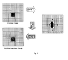
- FIGs 3a and 3b is shown the zone distribution of a thorax in varied lying positions.
- the zone distribution of a thorax in neutral supine position ( Figure 3a ) is compared with the zone distribution of a thorax in sideways turned supine position ( Figure 3b ).
- angle ⁇ is defined by the position of the dorsoventral axis 19 with respect to the gravity vector g.
- gravity vector g equals to gravity vector component g c .
- in lying position e.g.
- ⁇ is the angle between the dorsoventral saggital axis and the gravity vector component g c .
- ⁇ is the angle between the dorsoventral axis 19 and the gravity vector component g c .
- the dependency of the zone formation on the rotation around the longitudinal axis 17 of the patient is reflected in an asymmetry of the zone distribution in the two lungs.
- the zones are stacked in layers that are perpendicular to the gravitational vector g. If the body is turned to one side by the angle ⁇ , the zones still follow gravity as shown in Figure 3b .
- the angle ⁇ of the gravity vector g relative to the body axis remains unchanged at 90 degrees.
- the gravitational vector lies within the observation plane and the zones are maximally expressed.
- the mechanically ventilated lung situated lower i.e. the right lung in Figure 3b
- the other lung i.e. left lung
- FIG 4 left side, various positions of the patient (schematic of the thorax) are depicted with respect to the gravitational vector g.
- On the right side are shown respective angles ⁇ and ⁇ by which the two coordinate systems u/h and u'/h' are related to each other. Both coordinate systems have the same point of origin.
- ⁇ represents the angle between the main body axis 17 and the gravity vector g
- ⁇ represents the angle between the dorsoventral axis 19 and the gravity vector component gc.
- Vectors ⁇ u ' and ⁇ h ' result from the respective rotation of the u'/h' axis system versus the u/h axis system and define a rotated variant of the spatial filtering (see below).
- the invention combines spatial sensor data (which are preferably measured with a tri-axial acceleration sensor, for determining the orientation) and temporal sensor data (which are for example measured with a dilation sensor, a further acceleration sensor and/or an electrical and/or acoustic activity sensor) to improve the images and related information obtained by EIT.
- spatial sensor data which are preferably measured with a tri-axial acceleration sensor, for determining the orientation
- temporal sensor data which are for example measured with a dilation sensor, a further acceleration sensor and/or an electrical and/or acoustic activity sensor
- the excursion (i.e. dilation or expansion) of the belt-like structure, or parts of the belt-like structure is measured, for example by a strain gauge.
- a signal processor calculates the deviation from a local minimum and subsequently projects the onset of inhalation back in time.
- the data vector that was measured at that back-projected point in time is taken as the "breath reference vector". Since this procedure involves a certain delay in image processing, the goal of implementation is to find the balance between accuracy and timing. Since breathing in adults is done at frequencies well above three breaths per minute and well below 50 breaths per minute, a delay of a few hundred milliseconds can be tolerated and should be sufficient to reliably generate the reference point in time.
- pulmonary function testing often relies on a test called “occlusion test” to measure the respiratory drive of a patient. Such a test is done in 100 milliseconds in adults and in children. Finally, the "breath reference vector" is subtracted from each EIT data vector, making visible impedance changes that are caused by breathing activities and ventilation.
- the dilation sensor (also called breath sensor) is measuring the force on the belt-like structure by means of a strain-gauge and the body position by means of a 3D acceleration sensor.
- the user may input two parameters c and d to adjust the image with respect to zones 1, 2, and 3.
- the sensor signal is converted to digital format, typically at 50 to 100 samples per second, and preferably analyzed digitally. Analysis may include a simple low-pass filter and subsequent determination of minimal force. Alternatively, analysis may be done as in Figure 5 , illustrating the analysis of a strain gauge signal to find the EIT reference vector in presence of significant signal drift.
- the local minimum of the strain gauge (solid arrows) is around 0.1 second before every zero crossing of its high-pass filtered derivative (dotted arrows).
- the sensor data typically from a strain gauge, is first filtered by a low-pass filter with a cut-off frequency of 20 Hz. Thereafter, a high-pass filter is employed with a cut-off frequency of 0.1 Hz. If the so filtered curve crosses the zero-line going from low force to high force (dotted arrows), the chest is starting to expand and thus this point is taken as "start of inhalation".
- the breathing activity is measured by a second acceleration sensor (e.g. replacing above mentioned strain gauge sensor). Since the chest is moving with every breath, the second acceleration sensor can sense this movement and turn it into a signal that can be used to indicate the onset of inhalation and to determine the reference vector as described above.
- a second acceleration sensor e.g. replacing above mentioned strain gauge sensor. Since the chest is moving with every breath, the second acceleration sensor can sense this movement and turn it into a signal that can be used to indicate the onset of inhalation and to determine the reference vector as described above.
- the same acceleration sensor measures both, the breathing activity and the direction (i.e. orientation) of the gravity vector relative to the observation plane.
- a 3D acceleration sensor may be used.
- the temporal data sensor is an electrical activity sensor, for example a sensor as used in electrocardiography (ECG), i.e. an electrocardiography sensor.
- ECG electrocardiography
- Such a sensor can be used to create reference images related to the onset of the heart contraction thereby creating a "heart reference data vector". Thereafter, the "heart reference data vector" is subtracted from each EIT data, making visible impedance changes that are caused by heart activity.
- the temporal data sensor is an acoustic activity sensor or microphone, for example a sensor as used in phonocardiography (PCG), i.e. a phonocardiography sensor.
- PCG phonocardiography
- Such a sensor can be used to create reference images related to the onset of the heart contraction thereby creating a "heart reference data vector". Thereafter, the "heart reference data vector" is subtracted from each EIT data, making visible impedance changes that are caused by heart activity.
- At least two temporal data sensors are combined with a spatial data sensor.
- a spatial data sensor For example, an electrical or acoustic activity sensor, e.g. a sensor as used in electrocardiography or phonocardiography, respectively, and a dilation sensor, e.g. a strain gauge sensor, are combined with a 3-D acceleration sensor (spatial data sensor). This allows to measure orientation of the observation plane with respect to the gravity and at the same time dilation of the electrode belt due to breathing and electrical activity due to cardiac activity.
- the present invention can be used to enhance the image quality of EIT devices in stand-alone monitors and in mechanical ventilators and anaesthesia machines. Such improvement can be done by either creating the enhanced images or by plotting the gravity vector directly on the image, or automatically rotating the image with respect to the gravitational vector thereby providing orientation to the user.
- a particular use of such improved EIT images is to initiate specific therapies such as recruitment manoeuvres, physiotherapy, or changes in posture and to measure the effectiveness of the therapeutic interventions.
- a typical application of the sensor device for EIT imaging, the EIT imaging instrument and EIT imaging method according to present invention is in mechanically ventilated intensive care patients. About 15% of these patients suffer from acute lung injury and more than 30% of these die. It is estimated that about half of these patients could be saved by adequate treatment. Such treatment involves lung recruitment to effectively minimize zones 2 and 3. However, lung recruitment manoeuvres entail risks. Clinicians therefore often use lung recruitments only when lung damage has already become obvious. Unfortunately, this is often too late. With the disclosed invention, a care provider would have the means to judge the need and the success of lung recruitment manoeuvres early in disease, save lives, and reduce cost of care.
- the context sensitive EIT can be used to optimize the body position of a patient with respect to lung function.
- the reconstruction problem is solved using the finite-element method (FEM).
- FEM finite-element method
- the FEM uses a mesh of triangular elements, defined by nodes, to discretize the space or surface of interest. Then the physics of the problem is applied to the mesh and the problem is solved using given boundary conditions.
- the application of this filter results in an image with filtered high spatial frequencies, i.e. a smoother image.
- the new cutoff frequencies are ⁇ u' and ⁇ h ' linked to the u' and h' axis respectively.
- F P T ⁇ P - 1 ⁇ P T ⁇ R .
- the invention proposes a sine function for the gamma function but it is understood that any other function could be used.
- the gamma function could also be a mathematical model that represents the physiological zones (1 to 3) expression described above.
- the same notice is also valid for the F function, because other spatial filtering shapes could be used, for example a rectangle or an ellipse.
Landscapes
- Health & Medical Sciences (AREA)
- Life Sciences & Earth Sciences (AREA)
- Engineering & Computer Science (AREA)
- General Health & Medical Sciences (AREA)
- Veterinary Medicine (AREA)
- Public Health (AREA)
- Biomedical Technology (AREA)
- Heart & Thoracic Surgery (AREA)
- Medical Informatics (AREA)
- Molecular Biology (AREA)
- Surgery (AREA)
- Animal Behavior & Ethology (AREA)
- Biophysics (AREA)
- Pathology (AREA)
- Physics & Mathematics (AREA)
- Physiology (AREA)
- Pulmonology (AREA)
- Nuclear Medicine, Radiotherapy & Molecular Imaging (AREA)
- Cardiology (AREA)
- Human Computer Interaction (AREA)
- Radiology & Medical Imaging (AREA)
- Dentistry (AREA)
- Oral & Maxillofacial Surgery (AREA)
- Measurement And Recording Of Electrical Phenomena And Electrical Characteristics Of The Living Body (AREA)
- Measurement Of The Respiration, Hearing Ability, Form, And Blood Characteristics Of Living Organisms (AREA)
Applications Claiming Priority (2)
| Application Number | Priority Date | Filing Date | Title |
|---|---|---|---|
| CH16382010 | 2010-10-07 | ||
| PCT/CH2011/000236 WO2012045188A1 (en) | 2010-10-07 | 2011-10-04 | Sensor device for electrical impedance tomography imaging, electrical impedance tomography imaging intrument and electrical impeance tomography method |
Publications (2)
| Publication Number | Publication Date |
|---|---|
| EP2624750A1 EP2624750A1 (en) | 2013-08-14 |
| EP2624750B1 true EP2624750B1 (en) | 2014-12-17 |
Family
ID=44146683
Family Applications (1)
| Application Number | Title | Priority Date | Filing Date |
|---|---|---|---|
| EP11767603.1A Active EP2624750B1 (en) | 2010-10-07 | 2011-10-04 | Sensor device for electrical impedance tomography imaging, electrical impedance tomography imaging instrument and electrical impedance tomography method |
Country Status (6)
| Country | Link |
|---|---|
| US (2) | US10548484B2 (enExample) |
| EP (1) | EP2624750B1 (enExample) |
| JP (2) | JP5865376B2 (enExample) |
| CN (1) | CN103153180B (enExample) |
| BR (1) | BR112013007147A2 (enExample) |
| WO (1) | WO2012045188A1 (enExample) |
Families Citing this family (39)
| Publication number | Priority date | Publication date | Assignee | Title |
|---|---|---|---|---|
| CN103153180B (zh) * | 2010-10-07 | 2015-07-29 | 斯威斯托姆公开股份有限公司 | 用于电阻抗断层成像的传感器装置、电阻抗断层成像装置和电阻抗断层成像方法 |
| WO2014054045A1 (en) * | 2012-10-03 | 2014-04-10 | Ramot At Tel-Aviv University Ltd. | Parametric electric impedance tomography of the chest |
| BR102012028367B1 (pt) * | 2012-11-06 | 2022-03-22 | Timpel S.A | Método e aparato para gerar e exibir uma representação simplificada de informações obtidas através de tomografia por impedância elétrica |
| DE102013203177A1 (de) * | 2013-02-26 | 2014-08-28 | Hamilton Medical Ag | System zur automatisierten Einstellung eines durch eine Beatmungseinrichtung vorgegebenen Drucks |
| US11457832B2 (en) * | 2013-07-02 | 2022-10-04 | School Juridical Person Kitasato Institute | Measurement device, shape estimation device, measurement method, shape estimation method, and non-transitory recording medium recording program |
| US10285618B2 (en) * | 2013-07-02 | 2019-05-14 | School Juridical Person Kitasato Institute | EIT measurement device, EIT measurement method and program |
| US10952634B2 (en) | 2013-10-04 | 2021-03-23 | Swisstom Ag | Electrical impedance tomography system |
| US10438631B2 (en) | 2014-02-05 | 2019-10-08 | Snap Inc. | Method for real-time video processing involving retouching of an object in the video |
| DE102014004392A1 (de) | 2014-03-26 | 2015-10-15 | Epsilon Bootes - Pi Entwicklung Von Trainingswissenschaftlichen Sportgeräten E.K. | Mobile Spiroergometrie, EEG, 4D-EIT mit 4D-Ultraschall, Startzeit Zwischenzeitregistration Eindzeit, Schwimm Laufwiederstand Zug gerät, Venen Arterien Wahrnehmende 4D-Kamera als Einheit oder Individuell im Verarbeitsprozessor Bio-Physiologische als Megani |
| US20170143224A1 (en) * | 2014-05-30 | 2017-05-25 | Timpel S.A. | Module for detecting bodily signals |
| CN104605850B (zh) * | 2015-01-19 | 2017-08-01 | 中山大学 | 一种基于电阻抗断层成像技术的膀胱尿量实时监测装置和方法 |
| US10116901B2 (en) | 2015-03-18 | 2018-10-30 | Avatar Merger Sub II, LLC | Background modification in video conferencing |
| CN105976411B (zh) * | 2016-05-18 | 2017-06-20 | 中国人民解放军第四军医大学 | 一种用于电阻抗断层成像数据采集系统的前置测量模块及标校方法 |
| CN105997096B (zh) * | 2016-06-22 | 2019-04-26 | 合肥诺和电子科技有限公司 | 基于3d加速计的电阻抗断层肺成像方法 |
| US11793418B2 (en) | 2016-11-11 | 2023-10-24 | Sentec Ag | Sensor belt and positioning aid for electro-impedance tomography imaging in neonates |
| KR101812587B1 (ko) * | 2016-11-18 | 2018-01-30 | 주식회사 바이랩 | 피험자의 영상 모니터링 장치 및 그 방법과, 영상 모니터링 시스템 |
| WO2018140509A1 (en) * | 2017-01-24 | 2018-08-02 | Analog Devices, Inc. | Multi-sensor device for monitoring health |
| WO2019060298A1 (en) | 2017-09-19 | 2019-03-28 | Neuroenhancement Lab, LLC | METHOD AND APPARATUS FOR NEURO-ACTIVATION |
| US11412946B2 (en) | 2017-11-14 | 2022-08-16 | Timpel Medical B.V. | Electrical impedance tomography device and system having a multi-dimensional electrode arrangement |
| US11717686B2 (en) | 2017-12-04 | 2023-08-08 | Neuroenhancement Lab, LLC | Method and apparatus for neuroenhancement to facilitate learning and performance |
| US12280219B2 (en) | 2017-12-31 | 2025-04-22 | NeuroLight, Inc. | Method and apparatus for neuroenhancement to enhance emotional response |
| US11478603B2 (en) | 2017-12-31 | 2022-10-25 | Neuroenhancement Lab, LLC | Method and apparatus for neuroenhancement to enhance emotional response |
| JP6731435B2 (ja) * | 2018-03-16 | 2020-07-29 | ティンペル・メディカル・ベー・フェー | 生体信号検出モジュール |
| US11364361B2 (en) | 2018-04-20 | 2022-06-21 | Neuroenhancement Lab, LLC | System and method for inducing sleep by transplanting mental states |
| KR102219685B1 (ko) * | 2018-06-18 | 2021-02-24 | 주식회사 바이랩 | 저호흡 모니터링 시스템 및 방법 |
| US11452839B2 (en) | 2018-09-14 | 2022-09-27 | Neuroenhancement Lab, LLC | System and method of improving sleep |
| DE102018008545A1 (de) * | 2018-11-01 | 2020-05-07 | Drägerwerk AG & Co. KGaA | Vorrichtung und Verfahren zur Elektro-lmpedanz-Tomographie (EIT) mit Ermittlung einer Herzregion |
| DE212020000509U1 (de) | 2019-01-14 | 2021-09-30 | Analog Devices International Unlimited Company | Multisensorvorrichtung zur Gesundheitsüberwachung |
| US12419533B2 (en) | 2019-05-20 | 2025-09-23 | Udayan Kanade | System and method for acquiring electrical impedance tomography data |
| US11786694B2 (en) | 2019-05-24 | 2023-10-17 | NeuroLight, Inc. | Device, method, and app for facilitating sleep |
| CN114641236A (zh) * | 2019-10-07 | 2022-06-17 | 提姆佩尔医疗有限责任公司 | 经由区域阻抗和患者定位评估肺部特征的装置、系统和方法 |
| JP7767288B2 (ja) | 2019-12-23 | 2025-11-11 | アリメトリー リミテッド | 電極パッチおよび接続システム |
| WO2021137136A1 (en) * | 2019-12-30 | 2021-07-08 | Timpel Medical B.V. | Assessing hemodynamics using electrical impedance measurements |
| JP2022006490A (ja) | 2020-06-24 | 2022-01-13 | 朝日インテック株式会社 | 医療システム、および、画像生成方法 |
| TWI740586B (zh) * | 2020-07-28 | 2021-09-21 | 麗臺科技股份有限公司 | 利用週期性生理訊號產生電阻抗體層成像方法與裝置 |
| CN112231997B (zh) * | 2020-09-25 | 2023-04-07 | 重庆大学 | 基于人体组织电导率精细化建模设计的胸腔电阻抗仿真方法 |
| CN114847913B (zh) * | 2022-04-14 | 2023-10-27 | 四川大学华西医院 | 一种生物电阻抗断层成像装置和方法 |
| CN115137340A (zh) * | 2022-05-16 | 2022-10-04 | 思澜科技(成都)有限公司 | 一种用于eit成像的装置、系统及方法 |
| WO2024127069A1 (en) | 2022-12-15 | 2024-06-20 | Ceske Vysoke Uceni Technicke V Praze | System for increasing precision of electric impedance tomography |
Family Cites Families (26)
| Publication number | Priority date | Publication date | Assignee | Title |
|---|---|---|---|---|
| US6005916A (en) | 1992-10-14 | 1999-12-21 | Techniscan, Inc. | Apparatus and method for imaging with wavefields using inverse scattering techniques |
| GB9226376D0 (en) | 1992-12-18 | 1993-02-10 | British Tech Group | Tomography |
| DE19857090A1 (de) | 1998-12-10 | 2000-06-29 | Stephan Boehm | Verfahren zur regionalen Bestimmung des alveolären Öffnens und des alveolären Schließens der Lunge |
| US7096061B2 (en) * | 2002-07-03 | 2006-08-22 | Tel-Aviv University Future Technology Development L.P. | Apparatus for monitoring CHF patients using bio-impedance technique |
| US7226422B2 (en) * | 2002-10-09 | 2007-06-05 | Cardiac Pacemakers, Inc. | Detection of congestion from monitoring patient response to a recumbent position |
| US8672852B2 (en) * | 2002-12-13 | 2014-03-18 | Intercure Ltd. | Apparatus and method for beneficial modification of biorhythmic activity |
| GB2396426B (en) * | 2002-12-21 | 2005-08-24 | Draeger Medical Ag | Artificial respiration system |
| DE10301202B3 (de) * | 2002-12-21 | 2004-01-22 | Dräger Medical AG & Co. KGaA | Beatmungssystem |
| DE10315863B4 (de) * | 2003-04-08 | 2013-03-14 | Dräger Medical GmbH | Elektrodengürtel |
| US20040236202A1 (en) | 2003-05-22 | 2004-11-25 | Burton Steven Angell | Expandable strap for use in electrical impedance tomography |
| WO2005044090A2 (en) * | 2003-11-04 | 2005-05-19 | General Hospital Corporation | Respiration motion detection and health state assessment system |
| US20050107833A1 (en) | 2003-11-13 | 2005-05-19 | Freeman Gary A. | Multi-path transthoracic defibrillation and cardioversion |
| JP4633374B2 (ja) * | 2004-03-10 | 2011-02-16 | 公立大学法人会津大学 | 生体センサ装置 |
| US20070163584A1 (en) | 2004-03-29 | 2007-07-19 | Kci Licensing, Inc. | Method and apparatus for controlling at least one ventilation parameter of an artificial ventilator for ventilating the lung of a patient in accordance with a plurality of lung positions |
| AU2006235722A1 (en) | 2005-04-14 | 2006-10-19 | Hidalgo Limited | Apparatus and system for monitoring |
| EP1903935B1 (en) | 2005-05-06 | 2016-11-16 | The General Hospital Corporation | Apparatuses for electrophysiological signal delivery and recording during mri |
| US9089275B2 (en) * | 2005-05-11 | 2015-07-28 | Cardiac Pacemakers, Inc. | Sensitivity and specificity of pulmonary edema detection when using transthoracic impedance |
| EP1962680A1 (en) * | 2005-12-20 | 2008-09-03 | Dixtal Biomedica Industria e Commercio Ltda. | Electrode assembly for electrical impedance tomography |
| CN101248989B (zh) * | 2007-02-25 | 2011-10-12 | 香港中文大学 | 一种生理参数的监测系统 |
| US8419649B2 (en) * | 2007-06-12 | 2013-04-16 | Sotera Wireless, Inc. | Vital sign monitor for measuring blood pressure using optical, electrical and pressure waveforms |
| US8140154B2 (en) * | 2007-06-13 | 2012-03-20 | Zoll Medical Corporation | Wearable medical treatment device |
| US8808193B2 (en) | 2007-09-11 | 2014-08-19 | Carefusion 207, Inc. | Regional oxygen uptake/perfusion measuring device and method |
| US20100198101A1 (en) * | 2007-09-24 | 2010-08-05 | Xubo Song | Non-invasive location and tracking of tumors and other tissues for radiation therapy |
| EP2228009B1 (en) * | 2009-03-09 | 2018-05-16 | Drägerwerk AG & Co. KGaA | Apparatus and method to determine functional lung characteristics |
| CN101564294B (zh) * | 2009-06-01 | 2011-04-20 | 中国人民解放军第四军医大学 | 一种结构信息融合的电阻抗断层成像方法 |
| CN103153180B (zh) | 2010-10-07 | 2015-07-29 | 斯威斯托姆公开股份有限公司 | 用于电阻抗断层成像的传感器装置、电阻抗断层成像装置和电阻抗断层成像方法 |
-
2011
- 2011-10-04 CN CN201180048483.7A patent/CN103153180B/zh active Active
- 2011-10-04 JP JP2013532023A patent/JP5865376B2/ja active Active
- 2011-10-04 EP EP11767603.1A patent/EP2624750B1/en active Active
- 2011-10-04 BR BR112013007147A patent/BR112013007147A2/pt not_active Application Discontinuation
- 2011-10-04 US US13/878,401 patent/US10548484B2/en active Active
- 2011-10-04 WO PCT/CH2011/000236 patent/WO2012045188A1/en not_active Ceased
-
2015
- 2015-10-09 JP JP2015200888A patent/JP6093421B2/ja active Active
-
2020
- 2020-01-09 US US16/738,769 patent/US11317815B2/en active Active
Also Published As
| Publication number | Publication date |
|---|---|
| JP2016039914A (ja) | 2016-03-24 |
| US20130190577A1 (en) | 2013-07-25 |
| JP5865376B2 (ja) | 2016-02-17 |
| US11317815B2 (en) | 2022-05-03 |
| EP2624750A1 (en) | 2013-08-14 |
| US20200146560A1 (en) | 2020-05-14 |
| US10548484B2 (en) | 2020-02-04 |
| BR112013007147A2 (pt) | 2016-06-14 |
| WO2012045188A1 (en) | 2012-04-12 |
| CN103153180B (zh) | 2015-07-29 |
| JP6093421B2 (ja) | 2017-03-08 |
| JP2013540523A (ja) | 2013-11-07 |
| CN103153180A (zh) | 2013-06-12 |
Similar Documents
| Publication | Publication Date | Title |
|---|---|---|
| US11317815B2 (en) | Sensor device for electrical impedance tomography imaging, electrical impedance tomography imaging instrument and electrical impedance tomography method | |
| Frerichs | Electrical impedance tomography (EIT) in applications related to lung and ventilation: a review of experimental and clinical activities | |
| CN113598726B (zh) | 用于确定和/或监测受试者的呼吸努力的肌电图膜片、装置和方法 | |
| Jafari Tadi et al. | Accelerometer‐based method for extracting respiratory and cardiac gating information for dual gating during nuclear medicine imaging | |
| JP2023502854A (ja) | 電気インピーダンス断層撮影を用いた心肺機能モニタリング方法及びシステム | |
| CN102525454A (zh) | 基于电阻抗测量来确定生理参数的系统和方法 | |
| Graf et al. | Electrical impedance tomography: Amplitudes of cardiac related impedance changes in the lung are highly position dependent | |
| Młyńczak et al. | Impedance pneumography: Is it possible? | |
| Hutten et al. | Relative impact of respiratory muscle activity on tidal flow and end expiratory volume in healthy neonates | |
| JP5469574B2 (ja) | 電気的インピーダンス断層像測定装置。 | |
| CN119969994B (zh) | 一种三维eit成像设备、方法及程序产品 | |
| Bayford et al. | Focus on advances in electrical impedance tomography | |
| Holder | Appendix B Introduction to biomedical electrical impedance tomography | |
| Haris et al. | Respiratory image analysis | |
| Putensen et al. | Electrical impedance tomography for monitoring of regional ventilation in critically III patients | |
| Cinel et al. | Dynamic lung imaging techniques in mechanically ventilated patients | |
| Sharp et al. | P83 Remote pulmonary function testing–computer gaming in the respiratory world | |
| Yerworth et al. | A new clinical data and image analysis tool for monitoring neonatal lung function | |
| WO2014117205A1 (en) | Method and system for clinical measurement of lung health | |
| Wu et al. | Clinical Research on the Application of Inertial Measurement Units in Respiratory Cycle Measurement | |
| Zhao et al. | Chest electrical impedance tomography and its clinical applications | |
| CN116801797A (zh) | 输出心电信号和呼吸信号的装置以及方法 | |
| Dargaville et al. | Monitoring Lung Volumes During Mechanical Ventilation | |
| JP2022021806A (ja) | 生体状態モニタリングシステム、これを備えるベッドシステム、及び生体状態モニタリング方法 | |
| Al-Dhaheri | Cardiovascular responses to high-altitude and high-G environments by impedance cardiography with enhanced signal processing algorithms |
Legal Events
| Date | Code | Title | Description |
|---|---|---|---|
| PUAI | Public reference made under article 153(3) epc to a published international application that has entered the european phase |
Free format text: ORIGINAL CODE: 0009012 |
|
| 17P | Request for examination filed |
Effective date: 20130506 |
|
| AK | Designated contracting states |
Kind code of ref document: A1 Designated state(s): AL AT BE BG CH CY CZ DE DK EE ES FI FR GB GR HR HU IE IS IT LI LT LU LV MC MK MT NL NO PL PT RO RS SE SI SK SM TR |
|
| DAX | Request for extension of the european patent (deleted) | ||
| GRAP | Despatch of communication of intention to grant a patent |
Free format text: ORIGINAL CODE: EPIDOSNIGR1 |
|
| INTG | Intention to grant announced |
Effective date: 20140717 |
|
| GRAS | Grant fee paid |
Free format text: ORIGINAL CODE: EPIDOSNIGR3 |
|
| GRAA | (expected) grant |
Free format text: ORIGINAL CODE: 0009210 |
|
| AK | Designated contracting states |
Kind code of ref document: B1 Designated state(s): AL AT BE BG CH CY CZ DE DK EE ES FI FR GB GR HR HU IE IS IT LI LT LU LV MC MK MT NL NO PL PT RO RS SE SI SK SM TR |
|
| REG | Reference to a national code |
Ref country code: GB Ref legal event code: FG4D |
|
| RIN1 | Information on inventor provided before grant (corrected) |
Inventor name: GAGGERO, PASCAL, OLIVIER Inventor name: ROBITAILLE, NICOLAS Inventor name: BRUNNER, JOSEF, X. |
|
| REG | Reference to a national code |
Ref country code: CH Ref legal event code: EP |
|
| REG | Reference to a national code |
Ref country code: IE Ref legal event code: FG4D |
|
| REG | Reference to a national code |
Ref country code: AT Ref legal event code: REF Ref document number: 701271 Country of ref document: AT Kind code of ref document: T Effective date: 20150115 |
|
| REG | Reference to a national code |
Ref country code: DE Ref legal event code: R096 Ref document number: 602011012366 Country of ref document: DE Effective date: 20150212 |
|
| PG25 | Lapsed in a contracting state [announced via postgrant information from national office to epo] |
Ref country code: LT Free format text: LAPSE BECAUSE OF FAILURE TO SUBMIT A TRANSLATION OF THE DESCRIPTION OR TO PAY THE FEE WITHIN THE PRESCRIBED TIME-LIMIT Effective date: 20141217 Ref country code: FI Free format text: LAPSE BECAUSE OF FAILURE TO SUBMIT A TRANSLATION OF THE DESCRIPTION OR TO PAY THE FEE WITHIN THE PRESCRIBED TIME-LIMIT Effective date: 20141217 Ref country code: NO Free format text: LAPSE BECAUSE OF FAILURE TO SUBMIT A TRANSLATION OF THE DESCRIPTION OR TO PAY THE FEE WITHIN THE PRESCRIBED TIME-LIMIT Effective date: 20150317 |
|
| REG | Reference to a national code |
Ref country code: LT Ref legal event code: MG4D |
|
| PG25 | Lapsed in a contracting state [announced via postgrant information from national office to epo] |
Ref country code: GR Free format text: LAPSE BECAUSE OF FAILURE TO SUBMIT A TRANSLATION OF THE DESCRIPTION OR TO PAY THE FEE WITHIN THE PRESCRIBED TIME-LIMIT Effective date: 20150318 Ref country code: HR Free format text: LAPSE BECAUSE OF FAILURE TO SUBMIT A TRANSLATION OF THE DESCRIPTION OR TO PAY THE FEE WITHIN THE PRESCRIBED TIME-LIMIT Effective date: 20141217 Ref country code: LV Free format text: LAPSE BECAUSE OF FAILURE TO SUBMIT A TRANSLATION OF THE DESCRIPTION OR TO PAY THE FEE WITHIN THE PRESCRIBED TIME-LIMIT Effective date: 20141217 Ref country code: SE Free format text: LAPSE BECAUSE OF FAILURE TO SUBMIT A TRANSLATION OF THE DESCRIPTION OR TO PAY THE FEE WITHIN THE PRESCRIBED TIME-LIMIT Effective date: 20141217 Ref country code: RS Free format text: LAPSE BECAUSE OF FAILURE TO SUBMIT A TRANSLATION OF THE DESCRIPTION OR TO PAY THE FEE WITHIN THE PRESCRIBED TIME-LIMIT Effective date: 20141217 |
|
| REG | Reference to a national code |
Ref country code: AT Ref legal event code: MK05 Ref document number: 701271 Country of ref document: AT Kind code of ref document: T Effective date: 20141217 |
|
| PG25 | Lapsed in a contracting state [announced via postgrant information from national office to epo] |
Ref country code: NL Free format text: LAPSE BECAUSE OF FAILURE TO SUBMIT A TRANSLATION OF THE DESCRIPTION OR TO PAY THE FEE WITHIN THE PRESCRIBED TIME-LIMIT Effective date: 20141217 |
|
| PG25 | Lapsed in a contracting state [announced via postgrant information from national office to epo] |
Ref country code: ES Free format text: LAPSE BECAUSE OF FAILURE TO SUBMIT A TRANSLATION OF THE DESCRIPTION OR TO PAY THE FEE WITHIN THE PRESCRIBED TIME-LIMIT Effective date: 20141217 Ref country code: RO Free format text: LAPSE BECAUSE OF FAILURE TO SUBMIT A TRANSLATION OF THE DESCRIPTION OR TO PAY THE FEE WITHIN THE PRESCRIBED TIME-LIMIT Effective date: 20141217 Ref country code: SK Free format text: LAPSE BECAUSE OF FAILURE TO SUBMIT A TRANSLATION OF THE DESCRIPTION OR TO PAY THE FEE WITHIN THE PRESCRIBED TIME-LIMIT Effective date: 20141217 Ref country code: PT Free format text: LAPSE BECAUSE OF FAILURE TO SUBMIT A TRANSLATION OF THE DESCRIPTION OR TO PAY THE FEE WITHIN THE PRESCRIBED TIME-LIMIT Effective date: 20150417 Ref country code: EE Free format text: LAPSE BECAUSE OF FAILURE TO SUBMIT A TRANSLATION OF THE DESCRIPTION OR TO PAY THE FEE WITHIN THE PRESCRIBED TIME-LIMIT Effective date: 20141217 Ref country code: CZ Free format text: LAPSE BECAUSE OF FAILURE TO SUBMIT A TRANSLATION OF THE DESCRIPTION OR TO PAY THE FEE WITHIN THE PRESCRIBED TIME-LIMIT Effective date: 20141217 |
|
| PG25 | Lapsed in a contracting state [announced via postgrant information from national office to epo] |
Ref country code: IS Free format text: LAPSE BECAUSE OF FAILURE TO SUBMIT A TRANSLATION OF THE DESCRIPTION OR TO PAY THE FEE WITHIN THE PRESCRIBED TIME-LIMIT Effective date: 20150417 Ref country code: AT Free format text: LAPSE BECAUSE OF FAILURE TO SUBMIT A TRANSLATION OF THE DESCRIPTION OR TO PAY THE FEE WITHIN THE PRESCRIBED TIME-LIMIT Effective date: 20141217 Ref country code: PL Free format text: LAPSE BECAUSE OF FAILURE TO SUBMIT A TRANSLATION OF THE DESCRIPTION OR TO PAY THE FEE WITHIN THE PRESCRIBED TIME-LIMIT Effective date: 20141217 |
|
| REG | Reference to a national code |
Ref country code: DE Ref legal event code: R097 Ref document number: 602011012366 Country of ref document: DE |
|
| PLBE | No opposition filed within time limit |
Free format text: ORIGINAL CODE: 0009261 |
|
| REG | Reference to a national code |
Ref country code: FR Ref legal event code: PLFP Year of fee payment: 5 |
|
| STAA | Information on the status of an ep patent application or granted ep patent |
Free format text: STATUS: NO OPPOSITION FILED WITHIN TIME LIMIT |
|
| PG25 | Lapsed in a contracting state [announced via postgrant information from national office to epo] |
Ref country code: DK Free format text: LAPSE BECAUSE OF FAILURE TO SUBMIT A TRANSLATION OF THE DESCRIPTION OR TO PAY THE FEE WITHIN THE PRESCRIBED TIME-LIMIT Effective date: 20141217 |
|
| 26N | No opposition filed |
Effective date: 20150918 |
|
| PG25 | Lapsed in a contracting state [announced via postgrant information from national office to epo] |
Ref country code: IT Free format text: LAPSE BECAUSE OF FAILURE TO SUBMIT A TRANSLATION OF THE DESCRIPTION OR TO PAY THE FEE WITHIN THE PRESCRIBED TIME-LIMIT Effective date: 20141217 |
|
| PG25 | Lapsed in a contracting state [announced via postgrant information from national office to epo] |
Ref country code: SI Free format text: LAPSE BECAUSE OF FAILURE TO SUBMIT A TRANSLATION OF THE DESCRIPTION OR TO PAY THE FEE WITHIN THE PRESCRIBED TIME-LIMIT Effective date: 20141217 |
|
| PG25 | Lapsed in a contracting state [announced via postgrant information from national office to epo] |
Ref country code: LU Free format text: LAPSE BECAUSE OF FAILURE TO SUBMIT A TRANSLATION OF THE DESCRIPTION OR TO PAY THE FEE WITHIN THE PRESCRIBED TIME-LIMIT Effective date: 20151004 Ref country code: BE Free format text: LAPSE BECAUSE OF FAILURE TO SUBMIT A TRANSLATION OF THE DESCRIPTION OR TO PAY THE FEE WITHIN THE PRESCRIBED TIME-LIMIT Effective date: 20141217 |
|
| PG25 | Lapsed in a contracting state [announced via postgrant information from national office to epo] |
Ref country code: MC Free format text: LAPSE BECAUSE OF FAILURE TO SUBMIT A TRANSLATION OF THE DESCRIPTION OR TO PAY THE FEE WITHIN THE PRESCRIBED TIME-LIMIT Effective date: 20141217 |
|
| REG | Reference to a national code |
Ref country code: IE Ref legal event code: MM4A |
|
| REG | Reference to a national code |
Ref country code: FR Ref legal event code: PLFP Year of fee payment: 6 |
|
| PG25 | Lapsed in a contracting state [announced via postgrant information from national office to epo] |
Ref country code: IE Free format text: LAPSE BECAUSE OF NON-PAYMENT OF DUE FEES Effective date: 20151004 |
|
| PG25 | Lapsed in a contracting state [announced via postgrant information from national office to epo] |
Ref country code: BG Free format text: LAPSE BECAUSE OF FAILURE TO SUBMIT A TRANSLATION OF THE DESCRIPTION OR TO PAY THE FEE WITHIN THE PRESCRIBED TIME-LIMIT Effective date: 20141217 Ref country code: HU Free format text: LAPSE BECAUSE OF FAILURE TO SUBMIT A TRANSLATION OF THE DESCRIPTION OR TO PAY THE FEE WITHIN THE PRESCRIBED TIME-LIMIT; INVALID AB INITIO Effective date: 20111004 Ref country code: SM Free format text: LAPSE BECAUSE OF FAILURE TO SUBMIT A TRANSLATION OF THE DESCRIPTION OR TO PAY THE FEE WITHIN THE PRESCRIBED TIME-LIMIT Effective date: 20141217 |
|
| PG25 | Lapsed in a contracting state [announced via postgrant information from national office to epo] |
Ref country code: CY Free format text: LAPSE BECAUSE OF FAILURE TO SUBMIT A TRANSLATION OF THE DESCRIPTION OR TO PAY THE FEE WITHIN THE PRESCRIBED TIME-LIMIT Effective date: 20141217 |
|
| PG25 | Lapsed in a contracting state [announced via postgrant information from national office to epo] |
Ref country code: MT Free format text: LAPSE BECAUSE OF FAILURE TO SUBMIT A TRANSLATION OF THE DESCRIPTION OR TO PAY THE FEE WITHIN THE PRESCRIBED TIME-LIMIT Effective date: 20141217 |
|
| REG | Reference to a national code |
Ref country code: FR Ref legal event code: PLFP Year of fee payment: 7 |
|
| PG25 | Lapsed in a contracting state [announced via postgrant information from national office to epo] |
Ref country code: TR Free format text: LAPSE BECAUSE OF FAILURE TO SUBMIT A TRANSLATION OF THE DESCRIPTION OR TO PAY THE FEE WITHIN THE PRESCRIBED TIME-LIMIT Effective date: 20141217 Ref country code: MK Free format text: LAPSE BECAUSE OF FAILURE TO SUBMIT A TRANSLATION OF THE DESCRIPTION OR TO PAY THE FEE WITHIN THE PRESCRIBED TIME-LIMIT Effective date: 20141217 |
|
| REG | Reference to a national code |
Ref country code: FR Ref legal event code: PLFP Year of fee payment: 8 |
|
| PG25 | Lapsed in a contracting state [announced via postgrant information from national office to epo] |
Ref country code: AL Free format text: LAPSE BECAUSE OF FAILURE TO SUBMIT A TRANSLATION OF THE DESCRIPTION OR TO PAY THE FEE WITHIN THE PRESCRIBED TIME-LIMIT Effective date: 20141217 |
|
| REG | Reference to a national code |
Ref country code: CH Ref legal event code: NV Representative=s name: HEPP WENGER RYFFEL AG, CH Ref country code: CH Ref legal event code: PFUS Owner name: SENTEC AG, CH Free format text: FORMER OWNER: SWISSTOM AG, CH |
|
| PGFP | Annual fee paid to national office [announced via postgrant information from national office to epo] |
Ref country code: GB Payment date: 20250821 Year of fee payment: 15 |
|
| PGFP | Annual fee paid to national office [announced via postgrant information from national office to epo] |
Ref country code: FR Payment date: 20250821 Year of fee payment: 15 |
|
| REG | Reference to a national code |
Ref country code: CH Ref legal event code: U11 Free format text: ST27 STATUS EVENT CODE: U-0-0-U10-U11 (AS PROVIDED BY THE NATIONAL OFFICE) Effective date: 20251101 |
|
| PGFP | Annual fee paid to national office [announced via postgrant information from national office to epo] |
Ref country code: DE Payment date: 20250819 Year of fee payment: 15 |
|
| PGFP | Annual fee paid to national office [announced via postgrant information from national office to epo] |
Ref country code: CH Payment date: 20251101 Year of fee payment: 15 |