EP2624267A1 - Electrolytic capacitor socket - Google Patents
Electrolytic capacitor socket Download PDFInfo
- Publication number
- EP2624267A1 EP2624267A1 EP11748867.6A EP11748867A EP2624267A1 EP 2624267 A1 EP2624267 A1 EP 2624267A1 EP 11748867 A EP11748867 A EP 11748867A EP 2624267 A1 EP2624267 A1 EP 2624267A1
- Authority
- EP
- European Patent Office
- Prior art keywords
- socket
- capacitor
- support
- housing
- leads
- Prior art date
- Legal status (The legal status is an assumption and is not a legal conclusion. Google has not performed a legal analysis and makes no representation as to the accuracy of the status listed.)
- Withdrawn
Links
Images





Classifications
-
- H—ELECTRICITY
- H01—ELECTRIC ELEMENTS
- H01G—CAPACITORS; CAPACITORS, RECTIFIERS, DETECTORS, SWITCHING DEVICES, LIGHT-SENSITIVE OR TEMPERATURE-SENSITIVE DEVICES OF THE ELECTROLYTIC TYPE
- H01G9/00—Electrolytic capacitors, rectifiers, detectors, switching devices, light-sensitive or temperature-sensitive devices; Processes of their manufacture
- H01G9/004—Details
- H01G9/08—Housing; Encapsulation
-
- H—ELECTRICITY
- H01—ELECTRIC ELEMENTS
- H01G—CAPACITORS; CAPACITORS, RECTIFIERS, DETECTORS, SWITCHING DEVICES, LIGHT-SENSITIVE OR TEMPERATURE-SENSITIVE DEVICES OF THE ELECTROLYTIC TYPE
- H01G2/00—Details of capacitors not covered by a single one of groups H01G4/00-H01G11/00
- H01G2/02—Mountings
- H01G2/06—Mountings specially adapted for mounting on a printed-circuit support
-
- H—ELECTRICITY
- H01—ELECTRIC ELEMENTS
- H01G—CAPACITORS; CAPACITORS, RECTIFIERS, DETECTORS, SWITCHING DEVICES, LIGHT-SENSITIVE OR TEMPERATURE-SENSITIVE DEVICES OF THE ELECTROLYTIC TYPE
- H01G9/00—Electrolytic capacitors, rectifiers, detectors, switching devices, light-sensitive or temperature-sensitive devices; Processes of their manufacture
- H01G9/004—Details
- H01G9/008—Terminals
-
- H—ELECTRICITY
- H01—ELECTRIC ELEMENTS
- H01R—ELECTRICALLY-CONDUCTIVE CONNECTIONS; STRUCTURAL ASSOCIATIONS OF A PLURALITY OF MUTUALLY-INSULATED ELECTRICAL CONNECTING ELEMENTS; COUPLING DEVICES; CURRENT COLLECTORS
- H01R12/00—Structural associations of a plurality of mutually-insulated electrical connecting elements, specially adapted for printed circuits, e.g. printed circuit boards [PCB], flat or ribbon cables, or like generally planar structures, e.g. terminal strips, terminal blocks; Coupling devices specially adapted for printed circuits, flat or ribbon cables, or like generally planar structures; Terminals specially adapted for contact with, or insertion into, printed circuits, flat or ribbon cables, or like generally planar structures
- H01R12/70—Coupling devices
- H01R12/7076—Coupling devices for connection between PCB and component, e.g. display
-
- H—ELECTRICITY
- H01—ELECTRIC ELEMENTS
- H01R—ELECTRICALLY-CONDUCTIVE CONNECTIONS; STRUCTURAL ASSOCIATIONS OF A PLURALITY OF MUTUALLY-INSULATED ELECTRICAL CONNECTING ELEMENTS; COUPLING DEVICES; CURRENT COLLECTORS
- H01R13/00—Details of coupling devices of the kinds covered by groups H01R12/70 or H01R24/00 - H01R33/00
- H01R13/46—Bases; Cases
- H01R13/52—Dustproof, splashproof, drip-proof, waterproof, or flameproof cases
-
- H—ELECTRICITY
- H05—ELECTRIC TECHNIQUES NOT OTHERWISE PROVIDED FOR
- H05K—PRINTED CIRCUITS; CASINGS OR CONSTRUCTIONAL DETAILS OF ELECTRIC APPARATUS; MANUFACTURE OF ASSEMBLAGES OF ELECTRICAL COMPONENTS
- H05K3/00—Apparatus or processes for manufacturing printed circuits
- H05K3/30—Assembling printed circuits with electric components, e.g. with resistors
- H05K3/32—Assembling printed circuits with electric components, e.g. with resistors electrically connecting electric components or wires to printed circuits
-
- H—ELECTRICITY
- H05—ELECTRIC TECHNIQUES NOT OTHERWISE PROVIDED FOR
- H05K—PRINTED CIRCUITS; CASINGS OR CONSTRUCTIONAL DETAILS OF ELECTRIC APPARATUS; MANUFACTURE OF ASSEMBLAGES OF ELECTRICAL COMPONENTS
- H05K2201/00—Indexing scheme relating to printed circuits covered by H05K1/00
- H05K2201/10—Details of components or other objects attached to or integrated in a printed circuit board
- H05K2201/10007—Types of components
- H05K2201/10015—Non-printed capacitor
-
- H—ELECTRICITY
- H05—ELECTRIC TECHNIQUES NOT OTHERWISE PROVIDED FOR
- H05K—PRINTED CIRCUITS; CASINGS OR CONSTRUCTIONAL DETAILS OF ELECTRIC APPARATUS; MANUFACTURE OF ASSEMBLAGES OF ELECTRICAL COMPONENTS
- H05K2201/00—Indexing scheme relating to printed circuits covered by H05K1/00
- H05K2201/10—Details of components or other objects attached to or integrated in a printed circuit board
- H05K2201/10227—Other objects, e.g. metallic pieces
- H05K2201/10325—Sockets, i.e. female type connectors comprising metallic connector elements integrated in, or bonded to a common dielectric support
-
- H—ELECTRICITY
- H05—ELECTRIC TECHNIQUES NOT OTHERWISE PROVIDED FOR
- H05K—PRINTED CIRCUITS; CASINGS OR CONSTRUCTIONAL DETAILS OF ELECTRIC APPARATUS; MANUFACTURE OF ASSEMBLAGES OF ELECTRICAL COMPONENTS
- H05K3/00—Apparatus or processes for manufacturing printed circuits
- H05K3/30—Assembling printed circuits with electric components, e.g. with resistors
- H05K3/306—Assembling printed circuits with electric components, e.g. with resistors with lead-in-hole components
-
- H—ELECTRICITY
- H05—ELECTRIC TECHNIQUES NOT OTHERWISE PROVIDED FOR
- H05K—PRINTED CIRCUITS; CASINGS OR CONSTRUCTIONAL DETAILS OF ELECTRIC APPARATUS; MANUFACTURE OF ASSEMBLAGES OF ELECTRICAL COMPONENTS
- H05K3/00—Apparatus or processes for manufacturing printed circuits
- H05K3/30—Assembling printed circuits with electric components, e.g. with resistors
- H05K3/32—Assembling printed circuits with electric components, e.g. with resistors electrically connecting electric components or wires to printed circuits
- H05K3/34—Assembling printed circuits with electric components, e.g. with resistors electrically connecting electric components or wires to printed circuits by soldering
- H05K3/341—Surface mounted components
- H05K3/3421—Leaded components
Definitions
- the present invention relates to a socket for electrolytic capacitors and, more specifically, the present invention relates to a socket for electrolytic capacitors, by which relatively short-lived electrolytic capacitors can be replaced by new ones and an electric circuit can also be used with the newly replaced electrolytic capacitors.
- the electrolytic capacitor is incorporated in, for example, a smoothing circuit, together with circuit components.
- the circuit components can be used for a long time. Contrarily, the life of the electrolytic capacitor is relatively short. In particular, a life of the low capacitance capacitor is shorter than that of high capacitance capacitor. This results in that the life of the circuit is determined by, among others, the life of low capacitance capacitor.
- the electrolytic capacitor which has reached the end of its life should be replaced with new one.
- the electrolytic capacitor is securely fixed by means of press fitting or soldering.
- an electrolytic capacitor disclosed in the Japanese Utility Model Publication No. 3-68386 A comprises a plate-like socket base which has electrically conductive legs extending downward therefrom and a socket cover which is engaged with the socket base to securely hold the electrolytic capacitor mounted on the socket base.
- the conductive legs have respective holes defined therein for receiving the leads of the electrolytic capacitor.
- the lower ends of the legs extending coaxially with the leads are securely soldered to the circuit substrate with the socket base spaced away from the substrate.
- the electrolytic capacitor is fixed to and removed from the substrate simply by inserting and drawing the capacitor, respectively. This allows that the electrolytic capacitor which has reached the end of its life can be replaced with a new one and the circuit can be used for the newly replaced capacitor.
- the electrolytic capacitor 101 has a housing 103 for accommodating several components and electrolyte.
- Leads 104 and 105 are extended out through the lower end opening of the housing.
- the opening is closed by a rubber seal 106.
- an internal pressure within the housing may increase in response to atmospheric temperature, voltage and ripple current applied thereto or the like.
- the pressure increase causes an expansion of the rubber seal 106 as indicated in Fig. 15 by an imaginary line.
- the expanded rubber seal since it is in contact at its bottom surface with the socket base, forces its housing 107 away from the substrate, which loses a retaining force of the capacitor 101.
- the losing of the retaining force results in a reduction of resistance to vibrations, which may in turn degrade the circuit performance including an unwanted dropping of the electrolytic capacitor from the substrate to result in a cancellation of the advantages such as repetitive usage of the circuit.
- the present invention is to overcome the disadvantages such as reduction of the retaining force at the pressure increase within the electrolytic capacitor and thereby maintain the effectiveness of the repetitive usage of the circuit.
- a socket for an electrolytic capacitor having a housing and leads extending from a bottom surface of the housing, comprises a support for receiving the bottom surface of the capacitor; and connecting terminals for electrically connecting the leads to a circuit substrate; wherein the support comprises a holder for releasably holding a portion of the housing of the capacitor, the portion being adjacent to the leads, and the support further comprises a recess defined in a top surface of the support for accommodating a deformation of a seal rubber provided at a bottom portion of the housing of the capacitor.
- the electrolytic capacitor is releasably held by the holder. Also, the holder stabilizes the housing of the electrolytic capacitor and maintains a force for holding the electrolytic capacitor while allowing the deformation of the seal rubber.
- the support has a groove extending from an outer peripheral surface of the support to the recess. According to this arrangement, air moves through the connecting groove in response to expansions and contractions of the seal rubber, which ensures the expansions and contractions without any restriction and thereby maintains a holding force of the holder in a stable manner.
- the groove is positioned on a plane connecting the connecting terminals to which the leads are connected. This causes that the connecting groove passes through positions where the leads of the electrolytic capacitor are inserted, so that the groove works as a guide mark when holding the electrolytic capacitor by the holder.
- the bottom surface of the support defines a contact surface which will be brought into contact with the circuit substrate. This causes that, by the contact of the contact surface with the circuit substrate, the mounted socket is more stabilized to successfully resist vibrations than it is supported by the connecting terminals.
- the holder has an engaging means for engaging an associated constriction defined at the housing of the capacitor. This allows that the engaging means holds the electrolytic capacitor in a stable manner to prevent the electrolytic capacitor from dropping due to vibrations.
- the engaging means is made of an engaging spring which is extended downwardly from an upper portion of the holder and is elastically deformable in an inside-outside direction.
- This allows that the engaging spring is designed to be longer and therefore the capacitor is held firmly while reducing stress applied to the capacitor even for the commercially available products having differences in diameter of the housings thereof and/or in size and shape of the constrictions.
- each of the connecting terminals has a bottomed-hole into which the lead is inserted and a spring provided at an inner surface of the bottomed-hole for elastically holding the inserted lead.
- the bottomed-hole prevents a fluid leaked from the capacitor from reaching other portions such as circuit substrate.
- the electrolytic capacitor can be removed and therefore the circuit can be reused easily. Also, the recess of the support allows the deformations of the seal rubber while maintaining a stable holding of the capacitor by the holder. This in turn prevents the capacitor from dropping and allows the reuse of the capacitor while maintaining a reliable operation of the circuit.
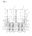
- Fig. 1 is a cross sectional view of a socket for electrolytic capacitors, showing an operational state of the socket;
- Fig. 2 is a perspective view of the socket for electrolytic capacitors
- Fig. 3 is a perspective view of the socket for electrolytic capacitors
- Fig. 4 is a plan view of the socket for electrolytic capacitors
- Fig. 5A is a cross sectional view taken along lines A-A in Fig. 4 ;
- Fig. 5B is a cross sectional view taken along lines B-B in Fig. 4 ;
- Fig. 6A is a cross sectional view showing a relationship between the socket for electrolytic capacitors and the electrolytic capacitor;
- Fig. 6B is a cross sectional view showing a relationship between the socket for electrolytic capacitors and the electrolytic capacitor;
- Fig. 7 is a side elevational view showing how the electrolytic capacitor is inserted in the socket for electrolytic capacitors
- Fig. 8A is a view showing a process for mounting the socket for electrolytic capacitors
- Fig. 8A is a view showing a process for mounting the socket for electrolytic capacitors
- Fig. 8A is a view showing a process for mounting the socket for electrolytic capacitors
- Fig. 9A is a view showing a process for mounting the socket for electrolytic capacitors
- Fig. 9B is a view showing a process for mounting the socket for electrolytic capacitors
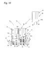
- Fig. 10 is a view showing an operational state of the socket for electrolytic capacitors
- Fig. 11 is a perspective view showing another embodiment of the socket for electrolytic capacitors
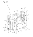
- Fig. 12 is a view showing another embodiment of the surface-mounting socket for electrolytic capacitors
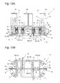
- Fig. 13A is a cross sectional view showing the surface-mounting socket for electrolytic capacitors in Fig. 12 ;
- Fig. 13B is a bottom view showing the surface-mounting socket for electrolytic capacitors in Fig. 12 ;
- Fig. 14 is a view showing an operational state of the surface-mounting socket for electrolytic capacitors in Fig. 12 ;
- Fig. 15 is a cross sectional view showing an internal structure of the conventional electrolytic capacitor.
- Fig. 1 shows a cross sectional view showing an operational state of a socket 11 for electrolytic capacitors.
- the socket 11 is securely mounted on a circuit substrate 51 by soldering, in which the socket 11 releasably holds electrolytic capacitors 61.
- the socket 11 is so designed that it can accommodate partial expansions of the capacitors which may be caused by the internal pressure increase in the electrolytic capacitors 61 and thereby maintain their stable holdings.
- the electrolytic capacitor 61 is a general purpose capacitor which comprises a housing 62 and two leads 63 and 64 as positive and negative terminals positioned at a bottom portion of the housing 62.
- Figs. 2 and 3 are perspective views of the socket 11 viewed from its above and below, respectively.
- Fig. 4 is a plan view and Figs. 5A and 5B are cross sectional views taken along lines A-A and B-B in Fig. 4 , respectively.
- the socket 11 comprises a support 12 for supporting the bottom surface of the housing 62 of the capacitor 61.
- the support 12 comprises a plurality of connecting terminals 31 for the electrical connections of the leads 63 and 64 extending from the housing 62 of the capacitor 61 to the associated portions of the circuit substrate 51.
- the support 12 further comprises a holder 13 formed therewith for releasably holding portions of housings 62 of the electrolytic capacitors 61, adjacent to the leads 63, 64.
- the support 12 also comprises a plurality of recesses 14 formed at the top portions thereof for accommodating expansions of the rubber seals 65 sealingly fitted in respective bottom openings of the housings 62 of the electrolytic capacitors 61 (see Fig. 1 ).
- the support 12 and the holder 13 are integrally formed with each other.
- the support 12 is designed to have substantially a rectangular configuration when viewed from above, which allows that two electrolytic capacitors 61 are arranged side by side on the support 12 with their leads 63 and 64 oriented downwardly.
- the holder 13 is provided to extend upwardly from peripheral portions of the top surface of the support 12.
- the holder 13 may be a hollow cylinder capable of surrounding substantially an entire portion of the housing 62 of the electrolytic capacitor 61, as shown in Figs. 2 and 4 it is designed to have a plurality of cutouts 16 in this embodiment.
- the holder 13 has an inside holder portion 13a provided at an intermediate portion of the support 12 with respect to its longitudinal direction and two pairs of outside holder portions 13b provided at the four corners of the support 12.
- the inside and outside holder portions 13a and 13b are so arranged to form the cutouts 16 between the inside and outside holder portions 13a and 13b and between the outside holding portions 13b, r respectively, which allows that peripheral three surface portions of each electrolytic capacitor 61 held on the support 12 are exposed between the neighboring holding portions.
- Each holder 13 is designed to have a certain height needed for holding the housing 62 of the electrolytic capacitor 61 with a suitable holding force.
- Each of the two paired outside holder portions 13b has an engaging means to make a secure engagement with an associated recess or constriction 62a formed in the housing 62 of the electrolytic capacitor 61, allowing the holder to securely hold the housing 62 of the electrolytic capacitor 61.
- the engaging means may be made of elongated projections formed integrally on an internal peripheral surface of the holder 13, as shown in Fig. 5B it is constituted by engaging springs 17 capable of moving elastically in radial directions in the embodiment.
- the engaging springs 17 are formed at intermediate portions of outside holder portions 13b with respect to the widthwise directions thereof to extend downwardly from upper portions thereof.
- the distal ends of the engaging springs 17 have projections 17a integrally formed therewith and projecting inwardly therefrom.
- the projections 17a are so positioned and sized as to engage with the associated constrictions 62a of the housing 62 of the electrolytic capacitor 61.
- a height and shape of the projections and lengths of the leads 63 and 64 of the electrolytic capacitor 61 are so determined that the projections 17a of the engaging springs 17 do not engage with the associated constrictions 62a when the electrolytic capacitor 61 is not retained firmly as shown in Fig. 6A , but the projections 17a of the engaging springs 17 come to engage with the associated constrictions 62a with click actions when the electrolytic capacitor 61 has been securely retained as shown in Fig. 6B , which ensures a secure mounting of the electrolytic capacitor 61.
- peripheral portions of the support 12 inside the lower ends of the holder 13 so constructed have a flat surface portion 18 for supporting a lower end of the housing 62 of the electrolytic capacitor 61 (see Figs. 1 and 6A, 6B ).
- the recess 14 is formed inside the supporting surface portion 18 to oppose the lowermost end rubber seal 65 provided at the bottom opening of the housing 62 of the electrolytic capacitor 61 so that it can accommodate the deformation of the seal rubber 65.
- the recess 14 is circular in shape when viewed from above and has a suitable depth which is determined by an amount of expansion of the seal rubber 65.
- each through hole 19 is so designed that it has an upper larger diameter portion, a lower smaller diameter portion and a step 19a defined therebetween, which allows that the connecting terminal 31 is press fitted and securely held in the through hole 19.
- each pair of through holes 19 are arranged in parallel to each other and spaced away from each other in the longitudinal direction of the support 12.
- the support 12 comprises a connecting groove 20 defined therein to extend from the outer peripheral surface of the support 12 to the interior of the recess 14.
- the connecting groove 20 is configured to have a suitable width and depth and extend linearly along a plane connecting centers of the paired through holes 19.
- the groove 20 is formed in the support surface portion 18 across the cutout 16 between the neighboring outside holder portions 13b. This arrangement ensures that, as shown in Fig. 7 , the leads 63 and 64 of the electrolytic capacitor 61 are aligned with the connecting groove 20 by mounting the electrolytic capacitor 61 in the holder 13.
- the connecting groove may be extended in that line accordingly.
- the bottom surface of the support 12 defines a contact surface 21 to be brought into contact with the circuit substrate 51.
- the contact surface 21 has a pair of press-fitting projections 22 positioned on opposite sides with respect to the longitudinal direction of the support 12 and projecting downwardly (see Fig. 5A ).
- the press-fitting projections 22 are so designed that they are press-fitted in the associated fitting holes 52 defined in the circuit substrate 51.
- Each of the connecting terminals 31, which is made of electrically conductive metal material and has a pin-like configuration, has an insert hole 32 in the form of bottomed hole into which the lead is inserted as shown in Fig. 5A .
- the inner peripheral surface of the hole 32 has springs 33 for elastically holding the lead inserted in the hole 32.
- the connecting terminal 31 has an upper larger diameter portion 34 and a lower smaller diameter portion 35, both received within the through hole 19.
- the larger diameter portion 34 which defines the insert hole 32 therein, has a flange 34a which engages with the step 19a of the through-hole 19 and a peg 34b which engages in the smaller diameter portion of the through-hole 19 positioned below the step 19a.
- the larger diameter portion 34 has substantially cylinder-shaped and downwardly tapered spring 33 integrally formed therewith and made of leaf springs 33a, so that the spring 33 makes a stable contact with the inserted lead 63 or 64 to hold it releasably and securely.
- the smaller diameter portion 35 of the connecting terminal 31 is extended straight downwardly beyond the contact surface 21 of the support 12, which allows the through-hole mounting of the socket 11, similar to the lead components (see Fig. 1 ).
- the socket 11 so constructed is securely mounted on a predetermined position of the circuit substrate 51 by soldering for holding the electrolytic capacitors 61.
- the circuit substrate 51 comprises through-holes 53 in which the connecting terminals 31 of the socket 11 are received and fitting holes 52 in which the projections 22 on the contact surface 21 of the socket 11 are press-fitted.
- the socket 11 is mounted on the circuit substrate 51 so that the connecting terminals 31 and the projections 22 are inserted in the through-holes 53 and the fitting holes 52, respectively.
- the connecting terminals 31 are soldered by the flowing method (see Fig. 8B ). The soldering is simultaneously performed for other circuit components.
- the solder mounting of the socket 11 to the circuit substrate 51 causes the contact surface 21 of the support 12 to make a surface contact with the circuit substrate. This cooperates with the press-fittings of the projections to provide the socket with a stable mounting and an elevated resistance to vibrations.
- the leads 63 and 64 of the electrolytic capacitor 61 are opposed to the through-holes 19 (i.e., insert holes 32 of the connecting terminal 31) of the socket 11. Then, the leads 63 and 64 are inserted in the insert holes 32 while the housing 62 is received in the holder 13. In this operation, the positive and negative leads are connected to the associated positive and negative connecting terminals, respectively.
- a modification in which the connecting terminals 31 have different lengths (e.g., the positive terminal is longer than the negative terminal) or any mark is provided at the bottom of the recess 14 ensures a correct connection of the capacitor and the socket without mixing up positive and negative polarities.
- An automatic mounting of the capacitors 61 ensures the positive and negative leads to be pre-oriented precisely, so that there is no need to provide such marks.
- the support 12 has the connecting groove 20 as described above and the groove 20 may work as an appropriate guide for insertion of the capacitor (see Fig. 7 ).
- the insertions of the leads 63 and 64 can be performed without receiving excessive resistance because the peripheral walls of the insertion holes 32 are made of springs 33.
- the leads 63 and 64 are fully accommodated within the holes 32 of the contact terminals 31 to form stable electric contacts and connections with the contact terminal 31 by the biasing forces from the springs 31 provided in the insert holes 32. Also, the housing 62 of the capacitor 61 is firmly held by the engaging springs 17.
- the lowermost end surface of the housing 62 is in contact with the receiving surface portion 18 of the support 12 and thereby retained in a stable manner. This ensures an elevated resistance to vibrations, so that no considerable stress will act on the leads 63, 64 even in the vibration environment.
- the engaging springs 17 of the holder 13 are elastically forced outwardly and then the distal projections 17a are clickingly engaged with the constrictions 62a, which provides a comfortable click feeling at the completion of the mounting of the capacitor. This also ensures a stable mounting of the capacitor without causing any excessive stress to the housing 62.
- the engaging springs 17 of the holder 13 are extended downwardly, they can be designed to have a length longer than that when being extended upwardly, which ensures sufficient elastic deformations of the springs. Therefore, the commercially available and widely used electrolytic capacitors 61 can be retained firmly even when they have differences in diameter of the housings 62 and/or in size and shape of the constrictions 62a.
- the deformation is accommodated by the recess 14 of the support to prevent the housing 62 from being raised which would otherwise be caused by the deformation and to ensure a stable holding of the capacitor by the holder 13. Also, a liquid leaked from the capacitor, if any, is received by the recess 13 to prevent the leaked liquid from flowing into contacts with another components or portions. This is also prevented by the fact that the holes 32 of the connecting terminal 31 are designed as bottomed holes.
- the connecting groove 20 allows air to flow between the recess and the atmosphere, which prevents a pressure increase and decrease in the recess due to the deformations of the seal rubber 65 and an upward movement of the housing 62 which would otherwise be caused thereby. Therefore, the retaining force of the capacitor is maintained reliably.
- the deteriorated capacitors 61 can be dismounted from the socket 11 and replaced by new ones.
- the circuit on the circuit substrate can be used with the new capacitors, so that the circuit substrate 51 does not need to be discarded with the deteriorated capacitor.
- the capacitor 61 can be retained in a stable manner irrelevant to the deformations caused in the capacitor. Also, the capacitor 61 can work without being affected by vibrations. Further, the liquid leaked from the capacitor is prohibited from flowing into contact with other components. Therefore, the circuit is well reused for the newly replaced capacitors.
- Fig. 11 shows a socket 11 for which four electrolytic capacitors can be mounted.
- the support 12 and the holder 13 are suitably configured to receive a required number of electrolytic capacitors.
- Fig. 12 is a perspective view of another socket 11 for surface-mounting, rather than through-hole mounting.
- the socket 11 comprises a plurality of grooves 15 defined in the bottom surface of the support 12 for receiving and guiding angled and horizontally oriented smaller diameter portions 35 of the connecting terminals 31.
- the guide grooves 15 are provided for respective through-holes 19, i.e., one guide groove 15a extending in a longitudinal direction of the support 12 and four guide grooves 15b extending in a transverse direction of the support 12.
- Each fixing bracket 22 has a cutout 22a formed therein to define the guide groove 15a.
- the socket 11 so constructed is mounted on the surface of the circuit substrate 51 by the reflow soldering, to which the electrolytic capacitors are mounted. Therefore, as shown in Fig. 14 , the recess 14 works as described above and attains the advantages described above. Also, according to the embodiment, high capacitance capacitors can be surface-mounted. Further, the capacitors can be well protected from heat at the reflow soldering.
- the engaging means corresponds to the engaging spring 17 but it is not limited thereto and other modifications can be contemplated and employed.
- the number and/sizes of the electrolytic capacitors to be mounted on the socket are suitably determined.
Landscapes
- Engineering & Computer Science (AREA)
- Power Engineering (AREA)
- Microelectronics & Electronic Packaging (AREA)
- Manufacturing & Machinery (AREA)
- Structures For Mounting Electric Components On Printed Circuit Boards (AREA)
- Details Of Connecting Devices For Male And Female Coupling (AREA)
Abstract
The invention is to prevent any reduction of a force for holding an electrolytic capacitor even when an internal pressure is increased and increase an effectiveness of repetitive use of an electric circuit used therewith. For this purpose, a socket 11 for electrolytic capacitors has a support 12 for supporting a bottom surface of the capacitor 61 having a housing 62 and leads 63, 64 provided at the bottom surface thereof, the support surface 12 comprising connecting terminals 31 for electrically connecting the leads 63, 64 to a circuit substrate 51. The support 12 comprises a holder 13 formed therewith for releasably holding a portion of capacitor 61, adjacent the leads 63, 64, and a recess 14 formed therein for accommodating deformations of seal rubber 65 provided at the housing 62 of the capacitor 61.
Description
- The present invention relates to a socket for electrolytic capacitors and, more specifically, the present invention relates to a socket for electrolytic capacitors, by which relatively short-lived electrolytic capacitors can be replaced by new ones and an electric circuit can also be used with the newly replaced electrolytic capacitors.
- Typically, the electrolytic capacitor is incorporated in, for example, a smoothing circuit, together with circuit components.
- The circuit components can be used for a long time. Contrarily, the life of the electrolytic capacitor is relatively short. In particular, a life of the low capacitance capacitor is shorter than that of high capacitance capacitor. This results in that the life of the circuit is determined by, among others, the life of low capacitance capacitor.
- In order for the circuit to be used for a long time, the electrolytic capacitor which has reached the end of its life should be replaced with new one. Conventionally, however, the electrolytic capacitor is securely fixed by means of press fitting or soldering.
- For example, an electrolytic capacitor disclosed in the Japanese Utility Model Publication No.
3-68386 A - With the arrangement, the electrolytic capacitor is fixed to and removed from the substrate simply by inserting and drawing the capacitor, respectively. This allows that the electrolytic capacitor which has reached the end of its life can be replaced with a new one and the circuit can be used for the newly replaced capacitor.
- Conventionally, as shown in
Fig. 15 , theelectrolytic capacitor 101 has ahousing 103 for accommodating several components and electrolyte.Leads rubber seal 106. Accordingly, an internal pressure within the housing may increase in response to atmospheric temperature, voltage and ripple current applied thereto or the like. The pressure increase causes an expansion of therubber seal 106 as indicated inFig. 15 by an imaginary line. The expanded rubber seal, since it is in contact at its bottom surface with the socket base, forces itshousing 107 away from the substrate, which loses a retaining force of thecapacitor 101. - The losing of the retaining force results in a reduction of resistance to vibrations, which may in turn degrade the circuit performance including an unwanted dropping of the electrolytic capacitor from the substrate to result in a cancellation of the advantages such as repetitive usage of the circuit.
- Accordingly, the present invention is to overcome the disadvantages such as reduction of the retaining force at the pressure increase within the electrolytic capacitor and thereby maintain the effectiveness of the repetitive usage of the circuit.
- Therefore, a socket for an electrolytic capacitor having a housing and leads extending from a bottom surface of the housing, comprises a support for receiving the bottom surface of the capacitor; and connecting terminals for electrically connecting the leads to a circuit substrate; wherein the support comprises a holder for releasably holding a portion of the housing of the capacitor, the portion being adjacent to the leads, and the support further comprises a recess defined in a top surface of the support for accommodating a deformation of a seal rubber provided at a bottom portion of the housing of the capacitor.
- According to the arrangement, the electrolytic capacitor is releasably held by the holder. Also, the holder stabilizes the housing of the electrolytic capacitor and maintains a force for holding the electrolytic capacitor while allowing the deformation of the seal rubber.
- Preferably, the support has a groove extending from an outer peripheral surface of the support to the recess. According to this arrangement, air moves through the connecting groove in response to expansions and contractions of the seal rubber, which ensures the expansions and contractions without any restriction and thereby maintains a holding force of the holder in a stable manner.
- Preferably, the groove is positioned on a plane connecting the connecting terminals to which the leads are connected. This causes that the connecting groove passes through positions where the leads of the electrolytic capacitor are inserted, so that the groove works as a guide mark when holding the electrolytic capacitor by the holder.
- Preferably, the bottom surface of the support defines a contact surface which will be brought into contact with the circuit substrate. This causes that, by the contact of the contact surface with the circuit substrate, the mounted socket is more stabilized to successfully resist vibrations than it is supported by the connecting terminals.
- Preferably, the holder has an engaging means for engaging an associated constriction defined at the housing of the capacitor. This allows that the engaging means holds the electrolytic capacitor in a stable manner to prevent the electrolytic capacitor from dropping due to vibrations.
- Preferably, the engaging means is made of an engaging spring which is extended downwardly from an upper portion of the holder and is elastically deformable in an inside-outside direction. This allows that the engaging spring is designed to be longer and therefore the capacitor is held firmly while reducing stress applied to the capacitor even for the commercially available products having differences in diameter of the housings thereof and/or in size and shape of the constrictions.
- Preferably, each of the connecting terminals has a bottomed-hole into which the lead is inserted and a spring provided at an inner surface of the bottomed-hole for elastically holding the inserted lead. This allows that the spring makes an elastic contact with the lead to establish a reliable electric connection, which reduces a stress to be applied to the lead being inserted. The bottomed-hole prevents a fluid leaked from the capacitor from reaching other portions such as circuit substrate.
- As described above, according to the invention, since the electrolytic capacitor can be removed and therefore the circuit can be reused easily. Also, the recess of the support allows the deformations of the seal rubber while maintaining a stable holding of the capacitor by the holder. This in turn prevents the capacitor from dropping and allows the reuse of the capacitor while maintaining a reliable operation of the circuit.
-
Fig. 1 is a cross sectional view of a socket for electrolytic capacitors, showing an operational state of the socket; -
Fig. 2 is a perspective view of the socket for electrolytic capacitors; -
Fig. 3 is a perspective view of the socket for electrolytic capacitors; -
Fig. 4 is a plan view of the socket for electrolytic capacitors; -
Fig. 5A is a cross sectional view taken along lines A-A inFig. 4 ; -
Fig. 5B is a cross sectional view taken along lines B-B inFig. 4 ; -
Fig. 6A is a cross sectional view showing a relationship between the socket for electrolytic capacitors and the electrolytic capacitor; -
Fig. 6B is a cross sectional view showing a relationship between the socket for electrolytic capacitors and the electrolytic capacitor; -
Fig. 7 is a side elevational view showing how the electrolytic capacitor is inserted in the socket for electrolytic capacitors; -
Fig. 8A is a view showing a process for mounting the socket for electrolytic capacitors; -
Fig. 8A is a view showing a process for mounting the socket for electrolytic capacitors; -
Fig. 8A is a view showing a process for mounting the socket for electrolytic capacitors; -
Fig. 9A is a view showing a process for mounting the socket for electrolytic capacitors; -
Fig. 9B is a view showing a process for mounting the socket for electrolytic capacitors; -
Fig. 10 is a view showing an operational state of the socket for electrolytic capacitors; -
Fig. 11 is a perspective view showing another embodiment of the socket for electrolytic capacitors; -
Fig. 12 is a view showing another embodiment of the surface-mounting socket for electrolytic capacitors; -
Fig. 13A is a cross sectional view showing the surface-mounting socket for electrolytic capacitors inFig. 12 ; -
Fig. 13B is a bottom view showing the surface-mounting socket for electrolytic capacitors inFig. 12 ; -
Fig. 14 is a view showing an operational state of the surface-mounting socket for electrolytic capacitors inFig. 12 ; and -
Fig. 15 is a cross sectional view showing an internal structure of the conventional electrolytic capacitor. - Referring to the accompanying drawings, an embodiment of the invention will be described.
Fig. 1 shows a cross sectional view showing an operational state of asocket 11 for electrolytic capacitors. As shown in the drawing, thesocket 11 is securely mounted on acircuit substrate 51 by soldering, in which thesocket 11 releasably holdselectrolytic capacitors 61. Also, thesocket 11 is so designed that it can accommodate partial expansions of the capacitors which may be caused by the internal pressure increase in theelectrolytic capacitors 61 and thereby maintain their stable holdings. In the embodiment, theelectrolytic capacitor 61 is a general purpose capacitor which comprises ahousing 62 and twoleads housing 62. - Discussions will be made to a general construction of the socket.
Figs. 2 and3 are perspective views of thesocket 11 viewed from its above and below, respectively.Fig. 4 is a plan view andFigs. 5A and 5B are cross sectional views taken along lines A-A and B-B inFig. 4 , respectively. As shown in the drawings, thesocket 11 comprises asupport 12 for supporting the bottom surface of thehousing 62 of thecapacitor 61. Thesupport 12 comprises a plurality of connectingterminals 31 for the electrical connections of theleads housing 62 of thecapacitor 61 to the associated portions of thecircuit substrate 51. Thesupport 12 further comprises aholder 13 formed therewith for releasably holding portions ofhousings 62 of theelectrolytic capacitors 61, adjacent to theleads support 12 also comprises a plurality ofrecesses 14 formed at the top portions thereof for accommodating expansions of the rubber seals 65 sealingly fitted in respective bottom openings of thehousings 62 of the electrolytic capacitors 61 (seeFig. 1 ). - Specifically, the
support 12 and theholder 13 are integrally formed with each other. Thesupport 12 is designed to have substantially a rectangular configuration when viewed from above, which allows that twoelectrolytic capacitors 61 are arranged side by side on thesupport 12 with theirleads holder 13 is provided to extend upwardly from peripheral portions of the top surface of thesupport 12. - Although the
holder 13 may be a hollow cylinder capable of surrounding substantially an entire portion of thehousing 62 of theelectrolytic capacitor 61, as shown inFigs. 2 and4 it is designed to have a plurality ofcutouts 16 in this embodiment. For example, theholder 13 has aninside holder portion 13a provided at an intermediate portion of thesupport 12 with respect to its longitudinal direction and two pairs ofoutside holder portions 13b provided at the four corners of thesupport 12. Also, the inside andoutside holder portions cutouts 16 between the inside andoutside holder portions outside holding portions 13b, r respectively, which allows that peripheral three surface portions of eachelectrolytic capacitor 61 held on thesupport 12 are exposed between the neighboring holding portions. - Each
holder 13 is designed to have a certain height needed for holding thehousing 62 of theelectrolytic capacitor 61 with a suitable holding force. - Each of the two paired outside
holder portions 13b has an engaging means to make a secure engagement with an associated recess orconstriction 62a formed in thehousing 62 of theelectrolytic capacitor 61, allowing the holder to securely hold thehousing 62 of theelectrolytic capacitor 61. - Although the engaging means may be made of elongated projections formed integrally on an internal peripheral surface of the
holder 13, as shown inFig. 5B it is constituted by engagingsprings 17 capable of moving elastically in radial directions in the embodiment. The engaging springs 17 are formed at intermediate portions ofoutside holder portions 13b with respect to the widthwise directions thereof to extend downwardly from upper portions thereof. The distal ends of the engagingsprings 17 haveprojections 17a integrally formed therewith and projecting inwardly therefrom. Theprojections 17a are so positioned and sized as to engage with the associatedconstrictions 62a of thehousing 62 of theelectrolytic capacitor 61. - A height and shape of the projections and lengths of the
leads electrolytic capacitor 61 are so determined that theprojections 17a of the engagingsprings 17 do not engage with the associatedconstrictions 62a when theelectrolytic capacitor 61 is not retained firmly as shown inFig. 6A , but theprojections 17a of the engagingsprings 17 come to engage with the associatedconstrictions 62a with click actions when theelectrolytic capacitor 61 has been securely retained as shown inFig. 6B , which ensures a secure mounting of theelectrolytic capacitor 61. - The peripheral portions of the
support 12 inside the lower ends of theholder 13 so constructed have aflat surface portion 18 for supporting a lower end of thehousing 62 of the electrolytic capacitor 61 (seeFigs. 1 and6A, 6B ). - The
recess 14 is formed inside the supportingsurface portion 18 to oppose the lowermostend rubber seal 65 provided at the bottom opening of thehousing 62 of theelectrolytic capacitor 61 so that it can accommodate the deformation of theseal rubber 65. Therecess 14 is circular in shape when viewed from above and has a suitable depth which is determined by an amount of expansion of theseal rubber 65. - An inside bottom surface of the
recess 14 has two throughholes 19 extending therethrough for receiving the connectingterminals 31 therein. As shown inFig. 5A , each throughhole 19 is so designed that it has an upper larger diameter portion, a lower smaller diameter portion and astep 19a defined therebetween, which allows that the connectingterminal 31 is press fitted and securely held in the throughhole 19. As shown inFig. 4 , each pair of throughholes 19 are arranged in parallel to each other and spaced away from each other in the longitudinal direction of thesupport 12. - As shown in
Figs. 1 ,2 and5A , thesupport 12 comprises a connectinggroove 20 defined therein to extend from the outer peripheral surface of thesupport 12 to the interior of therecess 14. The connectinggroove 20 is configured to have a suitable width and depth and extend linearly along a plane connecting centers of the paired throughholes 19. For example, as shown inFigs. 2 and4 , thegroove 20 is formed in thesupport surface portion 18 across thecutout 16 between the neighboringoutside holder portions 13b. This arrangement ensures that, as shown inFig. 7 , theleads electrolytic capacitor 61 are aligned with the connectinggroove 20 by mounting theelectrolytic capacitor 61 in theholder 13. - If the through
holes 19 are positioned on a different line, the connecting groove may be extended in that line accordingly. - Further, as shown in
Fig. 1 , the bottom surface of thesupport 12 defines acontact surface 21 to be brought into contact with thecircuit substrate 51. Thecontact surface 21 has a pair of press-fittingprojections 22 positioned on opposite sides with respect to the longitudinal direction of thesupport 12 and projecting downwardly (seeFig. 5A ). The press-fittingprojections 22 are so designed that they are press-fitted in the associatedfitting holes 52 defined in thecircuit substrate 51. - Each of the connecting
terminals 31, which is made of electrically conductive metal material and has a pin-like configuration, has aninsert hole 32 in the form of bottomed hole into which the lead is inserted as shown inFig. 5A . The inner peripheral surface of thehole 32 hassprings 33 for elastically holding the lead inserted in thehole 32. - Specifically, the connecting
terminal 31 has an upperlarger diameter portion 34 and a lowersmaller diameter portion 35, both received within the throughhole 19. Thelarger diameter portion 34, which defines theinsert hole 32 therein, has aflange 34a which engages with thestep 19a of the through-hole 19 and apeg 34b which engages in the smaller diameter portion of the through-hole 19 positioned below thestep 19a. Also, thelarger diameter portion 34 has substantially cylinder-shaped and downwardly taperedspring 33 integrally formed therewith and made ofleaf springs 33a, so that thespring 33 makes a stable contact with the insertedlead - The
smaller diameter portion 35 of the connectingterminal 31 is extended straight downwardly beyond thecontact surface 21 of thesupport 12, which allows the through-hole mounting of thesocket 11, similar to the lead components (seeFig. 1 ). - The
socket 11 so constructed is securely mounted on a predetermined position of thecircuit substrate 51 by soldering for holding theelectrolytic capacitors 61. - For this purpose, as shown in
Fig. 8A , thecircuit substrate 51 comprises through-holes 53 in which the connectingterminals 31 of thesocket 11 are received andfitting holes 52 in which theprojections 22 on thecontact surface 21 of thesocket 11 are press-fitted. This allows that thesocket 11 is mounted on thecircuit substrate 51 so that the connectingterminals 31 and theprojections 22 are inserted in the through-holes 53 and the fitting holes 52, respectively. Then, the connectingterminals 31 are soldered by the flowing method (seeFig. 8B ). The soldering is simultaneously performed for other circuit components. - The solder mounting of the
socket 11 to thecircuit substrate 51 causes thecontact surface 21 of thesupport 12 to make a surface contact with the circuit substrate. This cooperates with the press-fittings of the projections to provide the socket with a stable mounting and an elevated resistance to vibrations. - Next, as shown in
Fig. 9A , theleads electrolytic capacitor 61 are opposed to the through-holes 19 (i.e., insert holes 32 of the connecting terminal 31) of thesocket 11. Then, theleads housing 62 is received in theholder 13. In this operation, the positive and negative leads are connected to the associated positive and negative connecting terminals, respectively. A modification in which the connectingterminals 31 have different lengths (e.g., the positive terminal is longer than the negative terminal) or any mark is provided at the bottom of therecess 14 ensures a correct connection of the capacitor and the socket without mixing up positive and negative polarities. An automatic mounting of thecapacitors 61 ensures the positive and negative leads to be pre-oriented precisely, so that there is no need to provide such marks. - Further, the
support 12 has the connectinggroove 20 as described above and thegroove 20 may work as an appropriate guide for insertion of the capacitor (seeFig. 7 ). - Furthermore, the insertions of the
leads springs 33. - As shown in
Fig. 9B , when theelectrolytic capacitor 61 is received by thesocket 11, theleads holes 32 of thecontact terminals 31 to form stable electric contacts and connections with thecontact terminal 31 by the biasing forces from thesprings 31 provided in the insert holes 32. Also, thehousing 62 of thecapacitor 61 is firmly held by the engaging springs 17. - In this condition, the lowermost end surface of the
housing 62 is in contact with the receivingsurface portion 18 of thesupport 12 and thereby retained in a stable manner. This ensures an elevated resistance to vibrations, so that no considerable stress will act on theleads - Also, during the insertion of the
housing 62 of thecapacitor 61 into theholder 13, the engagingsprings 17 of theholder 13 are elastically forced outwardly and then thedistal projections 17a are clickingly engaged with theconstrictions 62a, which provides a comfortable click feeling at the completion of the mounting of the capacitor. This also ensures a stable mounting of the capacitor without causing any excessive stress to thehousing 62. - Further, since the engaging
springs 17 of theholder 13 are extended downwardly, they can be designed to have a length longer than that when being extended upwardly, which ensures sufficient elastic deformations of the springs. Therefore, the commercially available and widely usedelectrolytic capacitors 61 can be retained firmly even when they have differences in diameter of thehousings 62 and/or in size and shape of theconstrictions 62a. - Furthermore, when the internal pressure of the
electrolytic capacitor 61 is increased due to heat generated during operations thereof and thereby theseal rubber 65 is deformed by thermal expansion thereof, the deformation is accommodated by therecess 14 of the support to prevent thehousing 62 from being raised which would otherwise be caused by the deformation and to ensure a stable holding of the capacitor by theholder 13. Also, a liquid leaked from the capacitor, if any, is received by therecess 13 to prevent the leaked liquid from flowing into contacts with another components or portions. This is also prevented by the fact that theholes 32 of the connectingterminal 31 are designed as bottomed holes. - Moreover, the connecting
groove 20 allows air to flow between the recess and the atmosphere, which prevents a pressure increase and decrease in the recess due to the deformations of theseal rubber 65 and an upward movement of thehousing 62 which would otherwise be caused thereby. Therefore, the retaining force of the capacitor is maintained reliably. - As shown in
Figs. 10A and 10B, the deterioratedcapacitors 61 can be dismounted from thesocket 11 and replaced by new ones. The circuit on the circuit substrate can be used with the new capacitors, so that thecircuit substrate 51 does not need to be discarded with the deteriorated capacitor. - As described above, the
capacitor 61 can be retained in a stable manner irrelevant to the deformations caused in the capacitor. Also, thecapacitor 61 can work without being affected by vibrations. Further, the liquid leaked from the capacitor is prohibited from flowing into contact with other components. Therefore, the circuit is well reused for the newly replaced capacitors. - Other modifications will be described below. In the following descriptions, like parts are designated by like reference numerals and therefore no descriptions will be duplicated for those parts.
-
Fig. 11 shows asocket 11 for which four electrolytic capacitors can be mounted. As shown in the drawing, thesupport 12 and theholder 13 are suitably configured to receive a required number of electrolytic capacitors. -
Fig. 12 is a perspective view of anothersocket 11 for surface-mounting, rather than through-hole mounting. As shown inFig. 13 A , thesocket 11 comprises a plurality ofgrooves 15 defined in the bottom surface of thesupport 12 for receiving and guiding angled and horizontally orientedsmaller diameter portions 35 of the connectingterminals 31. As shown inFig. 13B , theguide grooves 15 are provided for respective through-holes 19, i.e., oneguide groove 15a extending in a longitudinal direction of thesupport 12 and fourguide grooves 15b extending in a transverse direction of thesupport 12. - The opposite end portions of the
contact surface 21 of thesupport 12 with respect to the longitudinal direction carry L-shapedfixing brackets 22 fixed thereto. The fixing clamps 22 are fixed at the mounting of thesocket 11. Each fixingbracket 22 has acutout 22a formed therein to define theguide groove 15a. - The
socket 11 so constructed is mounted on the surface of thecircuit substrate 51 by the reflow soldering, to which the electrolytic capacitors are mounted. Therefore, as shown inFig. 14 , therecess 14 works as described above and attains the advantages described above. Also, according to the embodiment, high capacitance capacitors can be surface-mounted. Further, the capacitors can be well protected from heat at the reflow soldering. - In the above-described arrangements and structures according to the several embodiments, the engaging means corresponds to the engaging
spring 17 but it is not limited thereto and other modifications can be contemplated and employed. For example, the number and/sizes of the electrolytic capacitors to be mounted on the socket are suitably determined. - Also, instead of the connecting terminals described above, another structure having a leaf spring, for example, and capable of retaining the leads may be used.
Claims (7)
- A socket for an electrolytic capacitor comprising a housing and leads extending from a bottom surface of the housing, comprising:a support for receiving the bottom surface of the capacitor; andconnecting terminals for electrically connecting the leads to a circuit substrate;whereinthe support comprises a holder for releasably holding a portion of the housing of the capacitor, the portion being adjacent to the leads,the support further comprises a recess defined in a top surface of the support for accommodating a deformation of a seal rubber provided at a bottom portion of the housing of the capacitor.
- The socket of claim 1, wherein the support has a groove extending from an outer peripheral surface of the support to the recess.
- The socket of claim 2, wherein the groove is positioned on a plane connecting the connecting terminals to which the leads are connected.
- The socket in any one of claims 1-3, wherein the support has a bottom surface which defines a contact surface which will make a contact with the circuit substrate.
- The socket in any one of claims 1-4, wherein the holder has an engaging means for engaging an associated recess defined at the housing of the capacitor.
- The socket of claim 5, wherein the engaging means is made of an engaging spring which is extended downwardly from an upper portion of the holder and is elastically deformable in an inside-outside direction.
- The socket in any one of claims 1-6, wherein each of the connecting terminals has a bottomed-hole into which the lead is inserted and a spring provided at an inner surface of the bottomed-hole for elastically holding the inserted lead.
Applications Claiming Priority (2)
| Application Number | Priority Date | Filing Date | Title |
|---|---|---|---|
| JP2010218607A JP2012074561A (en) | 2010-09-29 | 2010-09-29 | Socket for electrolytic capacitor |
| PCT/JP2011/056714 WO2012042936A1 (en) | 2010-09-29 | 2011-03-22 | Electrolytic capacitor socket |
Publications (1)
| Publication Number | Publication Date |
|---|---|
| EP2624267A1 true EP2624267A1 (en) | 2013-08-07 |
Family
ID=45892419
Family Applications (1)
| Application Number | Title | Priority Date | Filing Date |
|---|---|---|---|
| EP11748867.6A Withdrawn EP2624267A1 (en) | 2010-09-29 | 2011-03-22 | Electrolytic capacitor socket |
Country Status (6)
| Country | Link |
|---|---|
| US (1) | US20120077356A1 (en) |
| EP (1) | EP2624267A1 (en) |
| JP (1) | JP2012074561A (en) |
| CN (1) | CN102598171A (en) |
| TW (1) | TW201230560A (en) |
| WO (1) | WO2012042936A1 (en) |
Cited By (2)
| Publication number | Priority date | Publication date | Assignee | Title |
|---|---|---|---|---|
| CN105337093A (en) * | 2015-08-19 | 2016-02-17 | 富士康(昆山)电脑接插件有限公司 | Electric connector |
| DE102023136110A1 (en) * | 2023-12-20 | 2025-06-26 | Valeo Eautomotive Germany Gmbh | Arrangement comprising a DC link capacitor, corresponding manufacturing method and inverter |
Families Citing this family (24)
| Publication number | Priority date | Publication date | Assignee | Title |
|---|---|---|---|---|
| KR101472172B1 (en) * | 2007-09-26 | 2014-12-12 | 몰렉스 인코포레이티드 | Electrical component mounting assemblies |
| JP5725353B2 (en) * | 2011-08-11 | 2015-05-27 | 住友電装株式会社 | Connector with capacitor |
| FR2986657B1 (en) * | 2012-02-03 | 2014-01-31 | Batscap Sa | POSITIONING SPACER, ENERGY STORAGE MODULE THE ASSEMBLY AND METHOD FOR ASSEMBLING THE MODULE |
| KR20130112284A (en) * | 2012-04-03 | 2013-10-14 | 현대모비스 주식회사 | A capacitor carrier |
| JP5935760B2 (en) * | 2013-06-11 | 2016-06-15 | 住友電装株式会社 | Connector with electronic components |
| JP6065765B2 (en) * | 2013-06-28 | 2017-01-25 | 住友電装株式会社 | Connector with electronic components |
| CN104465074B (en) * | 2013-09-12 | 2018-04-17 | 伊顿公司 | For fixed and protective capacitor device |
| JP6322407B2 (en) * | 2013-12-24 | 2018-05-09 | Kyb株式会社 | Electronics |
| DE102014105114B4 (en) * | 2014-04-10 | 2022-12-29 | Semikron Elektronik Gmbh & Co. Kg | Converter arrangement with capacitor device |
| EP3029779B1 (en) | 2014-12-02 | 2018-03-21 | Samsung Electronics Co., Ltd. | Ac socket, power cord and display apparatus having the same |
| US9585255B2 (en) * | 2015-03-11 | 2017-02-28 | Raytheon Company | Component support for dense circuit board |
| DE102015214311A1 (en) * | 2015-07-29 | 2017-02-02 | Robert Bosch Gmbh | Electronic module with flexible placeable component via base element and method for manufacturing the same |
| CN108461282A (en) * | 2017-02-20 | 2018-08-28 | 罗伯特·博世有限公司 | Connector modules |
| DE102017105134B4 (en) * | 2017-03-10 | 2019-07-04 | Borgwarner Ludwigsburg Gmbh | Assembly aid for mounting electrical components on a printed circuit board and method for mounting electrical components on a printed circuit board |
| US10199753B2 (en) * | 2017-04-28 | 2019-02-05 | Corning Optical Communications Rf Llc | Multi-pin connector block assembly |
| CN110622335B (en) * | 2017-05-24 | 2023-04-04 | 松下知识产权经营株式会社 | Power storage module and power storage unit |
| JP2019186451A (en) * | 2018-04-13 | 2019-10-24 | 日本ケミコン株式会社 | Power storage device module and power storage device holder |
| US10716232B2 (en) * | 2018-08-22 | 2020-07-14 | Raytheon Company | Low profile, nesting capacitor collars |
| WO2020246195A1 (en) * | 2019-06-06 | 2020-12-10 | 日本ケミコン株式会社 | Capacitor and method for producing same, and capacitor-mounting method |
| JP7598085B2 (en) | 2019-06-06 | 2024-12-11 | 日本ケミコン株式会社 | Capacitor, manufacturing method thereof, and capacitor mounting method |
| US11581136B2 (en) * | 2020-03-25 | 2023-02-14 | Robert Bosch Llc | Capacitor carrier assembly with housing having expansion features |
| CN113571335B (en) * | 2021-06-03 | 2023-03-31 | 深圳市吉利通电子有限公司 | Intelligent high-frequency capacitor and manufacturing method thereof |
| JP2023140653A (en) * | 2022-03-23 | 2023-10-05 | パナソニックIpマネジメント株式会社 | Energy storage module |
| DE102024132723B3 (en) * | 2024-11-08 | 2025-12-31 | Danfoss Power Electronics A/S | Mounting bracket for an electrical device for holding capacitors, and device with this mounting bracket |
Family Cites Families (30)
| Publication number | Priority date | Publication date | Assignee | Title |
|---|---|---|---|---|
| US2874342A (en) * | 1953-06-23 | 1959-02-17 | Cinch Mfg Corp | Tube socket and capacitor assembly |
| US2901678A (en) * | 1956-10-05 | 1959-08-25 | Eitel Mccullough Inc | Electron tube socket |
| US3648337A (en) * | 1970-08-24 | 1972-03-14 | Mallory & Co Inc P R | Encapsulating of electronic components |
| US3880493A (en) * | 1973-12-28 | 1975-04-29 | Burroughs Corp | Capacitor socket for a dual-in-line package |
| JPH0368386U (en) * | 1989-11-08 | 1991-07-04 | ||
| JPH0655232U (en) * | 1992-12-29 | 1994-07-26 | 日本ケミコン株式会社 | Electrolytic capacitor |
| JPH06204098A (en) * | 1992-12-30 | 1994-07-22 | Nippon Chemicon Corp | Casing for electrolytic capacitor |
| US5403195A (en) * | 1994-05-24 | 1995-04-04 | The Whitaker Corporation | Socket having an auxiliary electrical component mounted thereon |
| JP3497242B2 (en) * | 1994-06-15 | 2004-02-16 | ニチコン株式会社 | Mounting structure of electrolytic capacitor |
| WO1997001263A1 (en) * | 1995-06-20 | 1997-01-09 | Matsushita Electric Industrial Co., Ltd. | Part holder, substrate having same, and method of manufacturing same |
| JPH09162061A (en) * | 1995-12-12 | 1997-06-20 | Hitachi Ltd | Capacitor connection method and connection device |
| JP3683344B2 (en) * | 1996-05-30 | 2005-08-17 | ニチコン株式会社 | Electrolytic capacitor |
| JPH10199772A (en) * | 1996-11-12 | 1998-07-31 | Toyo Denji Kikai Seisakusho:Kk | Electrolytic capacitor |
| JP3777748B2 (en) * | 1997-09-30 | 2006-05-24 | 株式会社ジーエス・ユアサコーポレーション | Assembled battery |
| JPH11233384A (en) * | 1998-02-18 | 1999-08-27 | Toyo Denji Kikai Seisakusho:Kk | Electrolytic capacitor and cap-type pedestal for electrolytic capacitor |
| KR200215511Y1 (en) * | 1998-03-03 | 2001-03-15 | 윤종용 | Socket, circuit board and sub-circuit board for integrated circuit device |
| JP2003156235A (en) * | 2001-11-20 | 2003-05-30 | Fujitsu General Ltd | Capacitor holder |
| JP3848565B2 (en) * | 2001-11-27 | 2006-11-22 | 松下電器産業株式会社 | Battery connection structure, battery module, and battery pack |
| JP2003264124A (en) * | 2002-03-08 | 2003-09-19 | Nippon Chemicon Corp | Chip type capacitor |
| US6623293B1 (en) * | 2002-04-03 | 2003-09-23 | Hon Hai Precision Ind. Co., Ltd. | Battery holder having means for securely retaining battery in position |
| US6717797B1 (en) * | 2002-11-22 | 2004-04-06 | Tyco Electronics Corporation | Apparatus, methods and articles of manufacture for a module box with integrated components |
| JP2004221182A (en) * | 2003-01-10 | 2004-08-05 | Matsushita Electric Ind Co Ltd | Capacitor device and method of manufacturing the same |
| JP2005033109A (en) * | 2003-07-10 | 2005-02-03 | Elna Co Ltd | Chip electronic component |
| JP2005209823A (en) * | 2004-01-21 | 2005-08-04 | Nippon Chemicon Corp | Electrolytic capacitor |
| US7287648B2 (en) * | 2005-09-02 | 2007-10-30 | Tools Aviation, Llc | Battery holder and dispenser |
| JP2007173311A (en) * | 2005-12-19 | 2007-07-05 | Yaskawa Electric Corp | Capacitor holder and capacitor vibration-proof structure using the same |
| DE112007000056T5 (en) * | 2006-09-29 | 2008-08-07 | Matsushita Electric Industrial Co., Ltd., Kadoma | Electronic component and electronic control device using this |
| JP4782044B2 (en) * | 2007-02-27 | 2011-09-28 | ニチコン株式会社 | Chip type aluminum electrolytic capacitor |
| JP2008270338A (en) * | 2007-04-17 | 2008-11-06 | Nichicon Corp | Chip type electrolytic capacitor |
| FR2916306B1 (en) * | 2007-05-15 | 2009-07-17 | Batscap Sa | MODULE FOR ELECTRIC ENERGY STORAGE ASSEMBLIES FOR DETECTING THE AGING OF THESE ASSEMBLIES. |
-
2010
- 2010-09-29 JP JP2010218607A patent/JP2012074561A/en active Pending
-
2011
- 2011-03-22 US US13/254,312 patent/US20120077356A1/en not_active Abandoned
- 2011-03-22 CN CN2011800013561A patent/CN102598171A/en active Pending
- 2011-03-22 WO PCT/JP2011/056714 patent/WO2012042936A1/en not_active Ceased
- 2011-03-22 EP EP11748867.6A patent/EP2624267A1/en not_active Withdrawn
- 2011-09-14 TW TW100132928A patent/TW201230560A/en unknown
Non-Patent Citations (1)
| Title |
|---|
| See references of WO2012042936A1 * |
Cited By (3)
| Publication number | Priority date | Publication date | Assignee | Title |
|---|---|---|---|---|
| CN105337093A (en) * | 2015-08-19 | 2016-02-17 | 富士康(昆山)电脑接插件有限公司 | Electric connector |
| CN105337093B (en) * | 2015-08-19 | 2018-11-09 | 富士康(昆山)电脑接插件有限公司 | Electric connector |
| DE102023136110A1 (en) * | 2023-12-20 | 2025-06-26 | Valeo Eautomotive Germany Gmbh | Arrangement comprising a DC link capacitor, corresponding manufacturing method and inverter |
Also Published As
| Publication number | Publication date |
|---|---|
| WO2012042936A1 (en) | 2012-04-05 |
| TW201230560A (en) | 2012-07-16 |
| US20120077356A1 (en) | 2012-03-29 |
| JP2012074561A (en) | 2012-04-12 |
| CN102598171A (en) | 2012-07-18 |
Similar Documents
| Publication | Publication Date | Title |
|---|---|---|
| EP2624267A1 (en) | Electrolytic capacitor socket | |
| EP2624268A1 (en) | Surface mount socket for electrolytic capacitor and surface mount method for electrolytic capacitor | |
| US10797428B2 (en) | Card edge connector with protective cover | |
| KR20090015787A (en) | Board-Mount Connectors | |
| WO2009010705A1 (en) | An electrical unit | |
| EP3783743A1 (en) | Electrical connector and electrical connector assembly | |
| US5352125A (en) | Anti-wicking electrical connector | |
| JP2013168324A (en) | Connector | |
| CN114342024A (en) | Capacitor, method for manufacturing the same, and method for mounting the same | |
| WO2009010704A1 (en) | An electrical unit | |
| KR100816619B1 (en) | Board mounted terminal construction | |
| US20190173205A1 (en) | Electrical connector | |
| JP2007095629A (en) | Terminal mounting structure and mounting method | |
| CN211126138U (en) | Crimping terminal and intelligent power module | |
| JP4084265B2 (en) | Press-fit contact and press-fit connector using the same | |
| CN219286793U (en) | Female end of connector | |
| CN219321678U (en) | Male end of connector | |
| CN223451235U (en) | Connector terminals, connectors, and connector assemblies | |
| JP4133895B2 (en) | Bottom entry type connector | |
| JP2007149663A (en) | Connector and its base | |
| JP2018078078A (en) | Connector and electronic component with connector | |
| CN116454666A (en) | Board-to-board connector | |
| JP2006310026A (en) | Socket connector | |
| KR100400487B1 (en) | Jack connecting in the printed circuit board | |
| KR200324360Y1 (en) | electricity connector |
Legal Events
| Date | Code | Title | Description |
|---|---|---|---|
| PUAI | Public reference made under article 153(3) epc to a published international application that has entered the european phase |
Free format text: ORIGINAL CODE: 0009012 |
|
| 17P | Request for examination filed |
Effective date: 20120326 |
|
| AK | Designated contracting states |
Kind code of ref document: A1 Designated state(s): AL AT BE BG CH CY CZ DE DK EE ES FI FR GB GR HR HU IE IS IT LI LT LU LV MC MK MT NL NO PL PT RO RS SE SI SK SM TR |
|
| STAA | Information on the status of an ep patent application or granted ep patent |
Free format text: STATUS: THE APPLICATION HAS BEEN WITHDRAWN |
|
| 18W | Application withdrawn |
Effective date: 20131022 |