EP2623939A1 - Messwertgeber sowie System mit einer Antriebseinheit und einem Messwertgeber - Google Patents
Messwertgeber sowie System mit einer Antriebseinheit und einem Messwertgeber Download PDFInfo
- Publication number
- EP2623939A1 EP2623939A1 EP12153822.7A EP12153822A EP2623939A1 EP 2623939 A1 EP2623939 A1 EP 2623939A1 EP 12153822 A EP12153822 A EP 12153822A EP 2623939 A1 EP2623939 A1 EP 2623939A1
- Authority
- EP
- European Patent Office
- Prior art keywords
- diffractive
- freedom
- drive unit
- dimensional
- transmitter
- Prior art date
- Legal status (The legal status is an assumption and is not a legal conclusion. Google has not performed a legal analysis and makes no representation as to the accuracy of the status listed.)
- Granted
Links
- 239000000463 material Substances 0.000 abstract description 14
- 230000005540 biological transmission Effects 0.000 abstract description 4
- 230000033001 locomotion Effects 0.000 description 4
- 239000000523 sample Substances 0.000 description 3
- 230000001419 dependent effect Effects 0.000 description 2
- 238000006243 chemical reaction Methods 0.000 description 1
- 238000001514 detection method Methods 0.000 description 1
- 238000011156 evaluation Methods 0.000 description 1
- 238000000034 method Methods 0.000 description 1
Images
Classifications
-
- G—PHYSICS
- G01—MEASURING; TESTING
- G01D—MEASURING NOT SPECIALLY ADAPTED FOR A SPECIFIC VARIABLE; ARRANGEMENTS FOR MEASURING TWO OR MORE VARIABLES NOT COVERED IN A SINGLE OTHER SUBCLASS; TARIFF METERING APPARATUS; MEASURING OR TESTING NOT OTHERWISE PROVIDED FOR
- G01D5/00—Mechanical means for transferring the output of a sensing member; Means for converting the output of a sensing member to another variable where the form or nature of the sensing member does not constrain the means for converting; Transducers not specially adapted for a specific variable
- G01D5/26—Mechanical means for transferring the output of a sensing member; Means for converting the output of a sensing member to another variable where the form or nature of the sensing member does not constrain the means for converting; Transducers not specially adapted for a specific variable characterised by optical transfer means, i.e. using infrared, visible, or ultraviolet light
- G01D5/32—Mechanical means for transferring the output of a sensing member; Means for converting the output of a sensing member to another variable where the form or nature of the sensing member does not constrain the means for converting; Transducers not specially adapted for a specific variable characterised by optical transfer means, i.e. using infrared, visible, or ultraviolet light with attenuation or whole or partial obturation of beams of light
- G01D5/34—Mechanical means for transferring the output of a sensing member; Means for converting the output of a sensing member to another variable where the form or nature of the sensing member does not constrain the means for converting; Transducers not specially adapted for a specific variable characterised by optical transfer means, i.e. using infrared, visible, or ultraviolet light with attenuation or whole or partial obturation of beams of light the beams of light being detected by photocells
- G01D5/36—Forming the light into pulses
- G01D5/38—Forming the light into pulses by diffraction gratings
-
- G—PHYSICS
- G01—MEASURING; TESTING
- G01D—MEASURING NOT SPECIALLY ADAPTED FOR A SPECIFIC VARIABLE; ARRANGEMENTS FOR MEASURING TWO OR MORE VARIABLES NOT COVERED IN A SINGLE OTHER SUBCLASS; TARIFF METERING APPARATUS; MEASURING OR TESTING NOT OTHERWISE PROVIDED FOR
- G01D2205/00—Indexing scheme relating to details of means for transferring or converting the output of a sensing member
- G01D2205/90—Two-dimensional encoders, i.e. having one or two codes extending in two directions
Definitions
- the invention initially relates to a drive unit which is movable in at least two degrees of freedom, that is to say, for example, rotationally and translationally, in which position information can be obtained with regard to the at least two degrees of freedom.
- a transmitter is provided, and thus the invention relates to a total of a system with such a drive unit and such a transmitter and on the other hand such a transmitter.
- Hall sensors for obtaining position information is known.
- a two-coordinate transmitter ie a transmitter system, which does not consist of two encoder systems for detecting position information with respect to independent degrees of freedom, one of which detects an axial position and a rotational angle, but both variables by means of one unit which summarizes the two previously independent encoder systems.
- a rotational body with a radially magnetized permanent magnet and to detect its magnetic field with at least one in the region of a rotational axis of the rotational body when the linear motion also occurs along this rotational axis.
- a multi-coordinate probe is known, with the position information can be generated in relation to two degrees of freedom.
- a ball-guided 3-coordinate probe is known with which even a detection of position information in relation to the three Cartesian coordinates should be possible.
- a disadvantage of these known systems are their sometimes not inconsiderable electrical and mechanical complexity, this particular applies to the probes, as well as the necessary mounting location and resulting problems.
- a Hall sensor which is mounted inside a linearly and rotationally movable rotary body, it must be ensured, for example, that neither the sensor nor a support required for its support comes into mechanical contact with it during a movement of the rotary body.
- a complex carrier is required for it.
- An object of the invention is to provide a further possibility for detecting two position information with respect to at least two degrees of freedom of a drive unit.
- a transmitting / receiving unit acts as a transducer, which interacts with a diffractive and two-dimensional measuring standard that can be attached to the rotational body by the transmitting / receiving unit, the diffractive, two-dimensional measuring scale is scanned.
- the invention can also be understood as a system having such a drive unit and a transmitter.
- the solution of the task is then carried out with a system having a drive unit and a transmitter, wherein the drive unit is movable in at least two degrees of freedom and wherein the drive unit acts on a rotary body by the rotary body has a diffractive, two-dimensional measuring scale and as transmitter a transmission / Receiving unit acts with in which the diffractive, two-dimensional material measure can be scanned.
- the advantage of the invention is that the material measure can be scanned without contact and the material measure can be applied in the form of a diffractive, two-dimensional measuring scale on an outer surface of the rotating body, so that also provided for the scanning transmitting / receiving unit can be located outside the body of revolution , As a result, the attachment of the two elements necessary for detecting the position information is largely problem-free.
- These elements are, on the one hand, the transmitting / receiving unit provided for scanning the measuring standard and, on the other hand, the diffractive, two-dimensional measuring standard.
- the two degrees of freedom of the drive system are a first translational degree of freedom and a second degree of rotational freedom.
- a translational and a subsequent or simultaneous rotational movement can be detected particularly well with a diffractive, two-dimensional measuring standard, which is applied to a rotational body which is likewise moved during such movement processes. If a motor shaft of the drive system or a cylinder rotatably connected to a motor shaft acts as a rotational body, no additional element is required when using the motor shaft.
- the diffractive, two-dimensional material measure in encoded form comprises absolute position information that can be read out with the transmitter / receiver unit.
- absolute position information can be read out, for example in the form as in the EP 1 677 081 B1 is described, can be dispensed with complex evaluations and conversions of otherwise available position information.
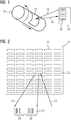
- FIG. 1 shows a rotary body 10 which, as indicated by the arrows, is rotatory and translationally movable.
- the illustrated rotary body 10 is a schematically simplified example of a motor shaft of a self-propelled drive unit, which is not known per se, or a cylinder rotatably connected to such a motor shaft.
- the rotary body 10 is thus an element of a drive system with at least two degrees of freedom, namely a rotational degree of freedom and a translational degree of freedom.
- Such a drive system comes into consideration in a manner known per se, for example for use in a machine tool, a robot or the like.
- a material measure which is a diffractive, two-dimensional material measure 12.
- This can be scanned with a transmitting / receiving unit 14, which is likewise shown only in a schematically simplified manner.
- a beam 16 emanating from the transmitting / receiving unit 14 is shown, which is normally a laser beam which strikes the diffractive, two-dimensional dimensional standard 12 and is diffracted and reflected there.
- a beam 18 emanating from the diffractive, two-dimensional measuring graduation 12 is shown.
- due to the diffraction it is a bundle of rays, which is received and evaluated by the transmitting / receiving unit 14.
- the diffractive, two-dimensional material measure 12 in encoded form comprises absolute position information
- FIG. 1 For a situation in which the diffractive, two-dimensional material measure 12 in encoded form comprises absolute position information, is shown in FIG. 1 in the inner transmitter / receiver unit 14, a pattern 20 is shown, as may result from a reflection / diffraction on the material measure 12.
- the pattern 20 can be evaluated, for example, according to a binary code, so that the respective position information results directly.
- FIG. 2 is a schematically simplified representation of a section of a diffractive, two-dimensional material measure 12.
- the illustration attempts to show that the material measure 12 comprises a large number of positions 22 arranged, for example, in rows and columns. These are diffractive microstructured fields. If the transmitting / receiving unit scans one of these positions 22 with a transmission beam 16, a reflection / diffraction 18 occurs, as is likewise simplified schematically and, for the special case, a coding of absolute position information in FIG FIG. 2 is shown.
- the resulting pattern 20 comprises a first and a second part 24, 26, wherein the first part 24, for example, a position information regarding a translational position of the rotating body 10 and the second part 26 a position information with respect to a translational position of the rotating body 10th reproduces.
Abstract
Description
- Die Erfindung betrifft zunächst eine Antriebseinheit, die in zumindest zwei Freiheitsgraden beweglich ist, also zum Beispiel rotatorisch und translatorisch, bei der hinsichtlich der zumindest zwei Freiheitsgrade eine Positionsinformation erhältlich ist. Zum Erhalt einer solchen Positionsinformation ist ein Messwertgeber vorgesehen und damit betrifft die Erfindung insgesamt einerseits ein System mit einer solchen Antriebseinheit und einem solchen Messwertgeber sowie andererseits einen solchen Messwertgeber.
- Bekannt ist die Verwendung von Hallsensoren zum Erhalt von Positionsinformationen. In Betracht kommt auch ein Zwei-Koordinaten-Geber, also ein Gebersystem, welches sich zur Erfassung von Positionsinformationen in Bezug auf unabhängige Freiheitsgrade nicht aus zwei Gebersystemen zusammensetzt, von denen eines eine axiale Position und eines einen Drehwinkel erfasst, sondern beide Größen mittels einer Einheit erfasst, in der die beiden bisher unabhängigen Gebersysteme zusammengefasst sind. Beispielhaft zu nennen wäre in diesem Zusammenhang eine Kombination zweier Inkrementalgeber. Im Hinblick auf eine Verwendung von Hallsensoren kommt in Betracht, einen Rotationskörper mit einem radial magnetisierten Permanentmagneten zu versehen und dessen Magnetfeld mit zumindest einem im Bereich einer Drehachse des Rotationskörpers, wenn entlang dieser Drehachse auch die Linearbewegung erfolgt, zu erfassen.
- Aus der
DE 43 25 743 C ist ein Mehrkoordinaten-Tastkopf bekannt, mit dem Positionsinformationen in Bezug auf zwei Freiheitsgrade generierbar sind. Aus derDE 38 42 032 C ist ein kugelgeführter 3-Koordinaten-Messtaster bekannt, mit dem sogar einen Erfassung von Positionsinformationen in Bezug die drei kartesischen Koordinaten möglich sein sollen. Nachteilig bei diesen bekannten Systemen sind deren teilweise nicht unerheblich elektrische und mechanische Komplexität, wobei dieses besondere für die Tastköpfe gilt, sowie der notwendige Anbringungsort und daraus resultierende Probleme. Bei einem Hallsensor, der im Innern eines linear und rotatorisch beweglichen Rotationskörpers angebracht ist, muss zum Beispiel sichergestellt sein, dass weder der Sensor noch ein für dessen Halterung erforderlicher Träger bei einer Bewegung des Rotationskörpers mit diesem in mechanischen Kontakt kommt. Je nach Umfang der Längserstreckung des Rotationskörpers ist dafür mitunter ein aufwändiger Träger erforderlich. - Eine Aufgabe der Erfindung besteht darin, eine weitere Möglichkeit zur Erfassung zweier Positionsinformationen in Bezug auf mindestens zwei Freiheitsgrade einer Antriebseinheit anzugeben.
- Diese Aufgabe wird erfindungsgemäß mit den Merkmalen der unabhängigen Ansprüche gelöst. Dazu ist bei einem Messwertgeber für eine Antriebseinheit, die in mindestens zwei Freiheitsgraden beweglich ist und auf einen Rotationskörper wirkt, vorgesehen, dass als Messwertgeber eine Sende-/Empfangseinheit fungiert, die mit einer an dem Rotationskörper anbringbaren, diffraktiven und zweidimensionalen Maßverkörperung zusammenwirkt, indem mit der Sende-/Empfangseinheit die diffraktive, zweidimensionale Maßverkörperung abtastbar ist. Bei einer am Rotationskörper der Antriebseinheit angebrachten Maßverkörperung kann die Erfindung auch als System mit einer solchen Antriebseinheit und einen Messwertgeber aufgefasst werden. Die Lösung der Aufgabe erfolgt dann mit einem System mit einer Antriebseinheit und einem Messwertgeber, wobei die Antriebseinheit in mindestens zwei Freiheitsgraden beweglich ist und wobei die Antriebseinheit auf einen Rotationskörper wirkt, indem der Rotationskörper eine diffraktive, zweidimensionale Maßverkörperung aufweist und als Messwertgeber eine Sende-/Empfangseinheit fungiert, mit dem die diffraktive, zweidimensionale Maßverkörperung abtastbar ist.
- Der Vorteil der Erfindung besteht darin, dass die Maßverkörperung berührungslos abtastbar ist und die Maßverkörperung in Form einer diffraktiven, zweidimensionale Maßverkörperung auf einer Außenoberfläche des Rotationskörpers aufgebracht werden kann, so dass sich auch die zu dessen Abtastung vorgesehene Sende-/Empfangseinheit außerhalb des Rotationskörpers befinden kann. Im Ergebnis ist die Anbringung der beiden zur Erfassung der Positionsinformationen erforderlichen Elemente weitgehend problemlos. Bei diesen Elementen handelt es sich einerseits um die zur Abtastung der Maßverkörperung vorgesehene Sende-/Empfangseinheit und andererseits um die diffraktive, zweidimensionale Maßverkörperung.
- Vorteilhafte Ausgestaltungen der Erfindung sind Gegenstand der Unteransprüche. Dabei verwendete Rückbeziehungen weisen auf die weitere Ausbildung des Gegenstandes des Hauptanspruches durch die Merkmale des jeweiligen Unteranspruches hin; sie sind nicht als ein Verzicht auf die Erzielung eines selbständigen, gegenständlichen Schutzes für die Merkmalskombinationen der rückbezogenen Unteransprüche zu verstehen. Des Weiteren ist im Hinblick auf eine Auslegung der Ansprüche bei einer näheren Konkretisierung eines Merkmals in einem nachgeordneten Anspruch davon auszugehen, dass eine derartige Beschränkung in den jeweils vorangehenden Ansprüchen nicht vorhanden ist.
- Bei einer Ausführungsform des Systems handelt es sich bei den beiden Freiheitsgraden des Antriebssystems um einen ersten, translatorischen Freiheitsgrad und einem zweiten, rotatorischen Freiheitsgrad. Eine translatorische und eine nachfolgende oder gleichzeitige rotatorische Bewegung lässt sich besonders gut mit einer diffraktiven, zweidimensionalen Maßverkörperung erfassen, die auf einem bei solchen Bewegungsvorgängen ebenfalls mitbewegten Rotationskörper aufgebracht ist. Wenn als Rotationskörper eine Motorwelle des Antriebssystems oder ein mit einer Motorwelle drehfest verbundener Zylinder fungiert, ist bei Verwendung der Motorwelle kein zusätzliches Element erforderlich. Bei Verwendung eines drehfest mit der Motorwelle verbundenen Zylinders besteht zusätzliche Flexibilität hinsichtlich der zum Anbringen der diffraktiven, zweidimensionalen Maßverkörperung zur Verfügung stehenden Fläche, denn bei einer Motorwelle mit einem vergleichsweise geringen Durchmesser kann für den mit der Motorwelle drehfest verbundenen Zylinder ein ausreichend großer Durchmesser gewählt werden, so dass die diffraktive, zweidimensionale Maßverkörperung in einer ausreichenden Auflösung auf der Außenoberfläche des Zylinders Platz findet.
- Bei einer Ausführungsform des Messwertgebers und/oder des Systems ist vorgesehen, dass die diffraktive, zweidimensionale Maßverkörperung in kodierter Form absolute Positionsinformationen umfasst, die mit der Sende-/Empfangseinheit auslesbar sind. Indem direkt absolute Positionsinformationen auslesbar sind, zum Beispiel in der Form wie dies in der
EP 1 677 081 B1 beschrieben ist, kann auf komplexe Auswertungen und Umrechnungen ansonsten erhältlicher Positionsinformationen verzichtet werden. - Nachfolgend wird ein Ausführungsbeispiel der Erfindung anhand der Zeichnung näher erläutert. Einander entsprechende Gegenstände oder Elemente sind in allen Figuren mit den gleichen Bezugszeichen versehen.
- Es zeigen
- FIG 1
- einen Rotationskörper mit einer diffraktiven, zweidimensionalen Maßverkörperung und eine Sende/Empfangseinheit zu deren Abtastung sowie
- FIG 2
- eine graphische Veranschaulichung einer diffraktiven, zweidimensionalen Maßverkörperung.
-
FIG 1 zeigt einen Rotationskörper 10 der, wie durch die Pfeile angedeutet, rotatorisch und translatorisch bewegbar ist. Der dargestellte Rotationskörper 10 ist ein schematisch vereinfachtes Beispiel für eine Motorwelle einer selbst nicht dargestellten, an sich bekannten Antriebseinheit oder für einen mit einer solchen Motorwelle drehfest verbundenen Zylinder. Der Rotationskörper 10 ist also Element eines Antriebssystems mit mindestens zwei Freiheitsgraden, nämlich einem rotatorischen Freiheitsgrad und einem translatorischen Freiheitsgrad. Ein solches Antriebssystem kommt in an sich bekannter Art und Weise beispielsweise zur Verwendung in einer Werkzeugmaschine, einen Roboter oder dergleichen in Betracht. - Auf dem Rotationskörper 10 befindet sich eine Maßverkörperung, bei der es sich um eine diffraktive, zweidimensionale Maßverkörperung 12 handelt. Diese ist mit einer ebenfalls nur schematisch vereinfacht darstellten Sende-/Empfangseinheit 14 abtastbar. Gezeigt ist dazu ein von der Sende-/Empfangseinheit 14 ausgehender Strahl 16, bei dem es sich normalerweise um einen Laserstrahl handelt, der auf die diffraktive, zweidimensionale Maßverkörperung 12 trifft und dort gebeugt und reflektiert wird. Zur Verdeutlichung der Reflektion ist ein von der diffraktiven, zweidimensionalen Maßverkörperung 12 ausgehender Strahl 18 gezeigt. Tatsächlich handelt es sich aufgrund der Diffraktion um ein Strahlenbüschel, das von der Sende-/Empfangseinheit 14 aufgenommen und ausgewertet wird.
- Für eine Situation, bei der die diffraktive, zweidimensionale Maßverkörperung 12 in kodierter Form absolute Positionsinformationen umfasst, ist in der Darstellung in
FIG 1 im Innern Sende-/Empfangseinheit 14 ein Muster 20 gezeigt, wie es sich aufgrund einer Reflektion/Diffraktion an der Maßverkörperung 12 ergeben kann. Das Muster 20 ist zum Beispiel nach einem Binärcode auswertbar, so dass sich unmittelbar die jeweilige Positionsinformation ergibt. -
FIG 2 ist eine schematisch vereinfachte Darstellung eines Ausschnitts aus einer diffraktiven, zweidimensionale Maßverkörperung 12. Die Darstellung versucht zu zeigen, dass die Maßverkörperung 12 eine Vielzahl von zum Beispiel in Zeilen und Spalten angeordneten Positionen 22 umfasst. Dabei handelt es sich um diffraktiv wirkende mikrostrukturierte Felder. Wenn die Sende-/Empfangseinheit eine dieser Positionen 22 mit einem Sendestrahl 16 abtastet, kommt es zu einer Reflektion/Diffraktion 18, wie diese ebenfalls schematisch vereinfacht und für den Sonderfall einer Kodierung von absoluten Positionsinformationen inFIG 2 gezeigt ist. Dort ist dargestellt, dass das resultierende Muster 20 einen ersten und einen zweiten Teil 24, 26 umfasst, wobei der erste Teil 24 zum Beispiel eine Positionsinformation hinsichtlich einer translatorischen Position des Rotationskörpers 10 und der zweite Teil 26 ein Positionsinformation hinsichtlich einer translatorischen Position des Rotationskörpers 10 wiedergibt. - Obwohl die Erfindung im Detail durch das Ausführungsbeispiel näher illustriert und beschrieben wurde, so ist die Erfindung nicht durch das oder die offenbarten Beispiele eingeschränkt und andere Variationen können vom Fachmann hieraus abgeleitet werden, ohne den Schutzumfang der Erfindung zu verlassen.
- Einzelne im Vordergrund stehende Aspekte der hier eingereichten Beschreibung lassen sich damit kurz wie folgt zusammenfassen:
- Angegeben werden ein Messwertgeber für eine Antriebseinheit, die in mindestens zwei Freiheitsgraden beweglich ist und auf einen Rotationskörper 10 wirkt, wobei als Messwertgeber eine Sende-/Empfangseinheit 14 fungiert, die mit einer an dem Rotationskörper 10 anbringbaren, diffraktiven und zweidimensionale Maßverkörperung 12 zusammenwirkt, indem mit der Sende-/Empfangseinheit 14 die diffraktive, zweidimensionale Maßverkörperung 12 abtastbar ist, sowie ein System mit einer solchen Antriebseinheit und einem solchen Messwertgeber.
Claims (5)
- Messwertgeber für eine Antriebseinheit, die in mindestens zwei Freiheitsgraden beweglich ist und auf einen Rotationskörper (10) wirkt, wobei als Messwertgeber eine Sende-/Empfangseinheit (14) fungiert, die mit einer an dem Rotationskörper (10) anbringbaren, diffraktiven und zweidimensionale Maßverkörperung (12) zusammenwirkt, indem mit der Sende-/Empfangseinheit (14) die diffraktive, zweidimensionale Maßverkörperung (12) abtastbar ist.
- System mit einer Antriebseinheit und einem Messwertgeber, wobei die Antriebseinheit in mindestens zwei Freiheitsgraden beweglich ist, wobei die Antriebseinheit auf einen Rotationskörper (10) wirkt, der eine diffraktive, zweidimensionale Maßverkörperung (12) aufweist, und wobei als Messwertgeber eine Sende-/Empfangseinheit (14) fungiert, mit dem die diffraktive, zweidimensionale Maßverkörperung (12) abtastbar ist.
- System nach Anspruch 2, mit einer Antriebseinheit mit einem ersten, translatorischen Freiheitsgrad und einem zweiten, rotatorischen Freiheitsgrad.
- System nach einem der vorangehenden Ansprüche, wobei der Rotationskörper (10) eine Motorwelle oder ein mit einer Motorwelle drehfest verbundener Zylinder ist.
- Messwertgeber nach Anspruch 1 oder System nach einem der Ansprüche 2 bis 4, wobei die diffraktive zweidimensionale Maßverkörperung (12) in kodierter Form absolute Positionsinformationen umfasst, die mit der Sende-/Empfangseinheit (14) auslesbar sind.
Priority Applications (1)
| Application Number | Priority Date | Filing Date | Title |
|---|---|---|---|
| EP12153822.7A EP2623939B1 (de) | 2012-02-03 | 2012-02-03 | Messwertgeber sowie System mit einer Antriebseinheit und einem Messwertgeber |
Applications Claiming Priority (1)
| Application Number | Priority Date | Filing Date | Title |
|---|---|---|---|
| EP12153822.7A EP2623939B1 (de) | 2012-02-03 | 2012-02-03 | Messwertgeber sowie System mit einer Antriebseinheit und einem Messwertgeber |
Publications (2)
| Publication Number | Publication Date |
|---|---|
| EP2623939A1 true EP2623939A1 (de) | 2013-08-07 |
| EP2623939B1 EP2623939B1 (de) | 2016-06-29 |
Family
ID=45562828
Family Applications (1)
| Application Number | Title | Priority Date | Filing Date |
|---|---|---|---|
| EP12153822.7A Not-in-force EP2623939B1 (de) | 2012-02-03 | 2012-02-03 | Messwertgeber sowie System mit einer Antriebseinheit und einem Messwertgeber |
Country Status (1)
| Country | Link |
|---|---|
| EP (1) | EP2623939B1 (de) |
Citations (7)
| Publication number | Priority date | Publication date | Assignee | Title |
|---|---|---|---|---|
| US5341211A (en) | 1989-09-13 | 1994-08-23 | Robert Bosch Gmbh | Apparatus for making absolute two-demensional position measurements |
| DE4317064A1 (de) | 1993-05-21 | 1994-11-24 | Bosch Gmbh Robert | Positionsmeßvorrichtung |
| EP0628791A2 (de) | 1993-06-10 | 1994-12-14 | Canon Kabushiki Kaisha | Vorrichtung und Skala zur Detektierung von Drehungen |
| EP1677081B1 (de) | 2004-12-30 | 2009-03-25 | Delphi Technologies Inc. | Verfahren zur Bestimmung der Stellung eines ersten Elements das sich relativ zu einem zweiten Element bewegt und Vorrichtung zur Durchführung des Verfahrens |
| US20090284723A1 (en) * | 2008-04-30 | 2009-11-19 | Nikon Corporation | Stage device, pattern formation apparatus, exposure apparatus, stage drive method, exposure method, and device manufacturing method |
| GB2465575A (en) * | 2008-11-21 | 2010-05-26 | Rolls Royce Plc | Displacement measurement / rotor blade pitch measurement arrangement |
| WO2012004091A1 (en) * | 2010-07-06 | 2012-01-12 | Rolls-Royce Plc | Axial displacement and rotational speed monitoring |
-
2012
- 2012-02-03 EP EP12153822.7A patent/EP2623939B1/de not_active Not-in-force
Patent Citations (7)
| Publication number | Priority date | Publication date | Assignee | Title |
|---|---|---|---|---|
| US5341211A (en) | 1989-09-13 | 1994-08-23 | Robert Bosch Gmbh | Apparatus for making absolute two-demensional position measurements |
| DE4317064A1 (de) | 1993-05-21 | 1994-11-24 | Bosch Gmbh Robert | Positionsmeßvorrichtung |
| EP0628791A2 (de) | 1993-06-10 | 1994-12-14 | Canon Kabushiki Kaisha | Vorrichtung und Skala zur Detektierung von Drehungen |
| EP1677081B1 (de) | 2004-12-30 | 2009-03-25 | Delphi Technologies Inc. | Verfahren zur Bestimmung der Stellung eines ersten Elements das sich relativ zu einem zweiten Element bewegt und Vorrichtung zur Durchführung des Verfahrens |
| US20090284723A1 (en) * | 2008-04-30 | 2009-11-19 | Nikon Corporation | Stage device, pattern formation apparatus, exposure apparatus, stage drive method, exposure method, and device manufacturing method |
| GB2465575A (en) * | 2008-11-21 | 2010-05-26 | Rolls Royce Plc | Displacement measurement / rotor blade pitch measurement arrangement |
| WO2012004091A1 (en) * | 2010-07-06 | 2012-01-12 | Rolls-Royce Plc | Axial displacement and rotational speed monitoring |
Also Published As
| Publication number | Publication date |
|---|---|
| EP2623939B1 (de) | 2016-06-29 |
Similar Documents
| Publication | Publication Date | Title |
|---|---|---|
| EP1364186B1 (de) | Multiturn-codedrehgeber | |
| EP2113742B2 (de) | Messvorrichtung mit Zwei-Kanal-Abtastung | |
| EP2182330B1 (de) | Positions-/Wegmesssystem mit kodiertem Masskörper | |
| EP1706708B1 (de) | Lenkwinkelsensor | |
| DE10060287A1 (de) | Vorrichtung zur Messung des Winkels und/oder der Winkelgeschwindigkeit eines drehbaren Körpers und/oder des auf ihn wirkenden Drehmoments | |
| DE102013208986A1 (de) | Magnetgeberring einer Rotorlagesensorik eines elektrisch kommutierten Elektromotors | |
| EP0953494A2 (de) | Vorrichtung zur Bestimmung des Masses der Verdrehung zwischen zwei Teilen | |
| EP0171612A1 (de) | Lagemesseinrichtung | |
| DE102008046741A1 (de) | Induktiver Positionssensor, damit ausgestattetes Messsystem und Verfahren zum Betrieb eines Positionssensors | |
| DE102012109787A1 (de) | Lenkwinkelsensor für Kraftfahrzeuge | |
| DE10310970B4 (de) | Vorrichtung zur Messung der Position, des Weges oder des Drehwinkels eines Objektes | |
| EP2017627A2 (de) | Induktive drehzahlerkennung | |
| EP1770372B1 (de) | Positionsmesseinrichtung | |
| EP1770375B1 (de) | Positionsmesseinrichtung mit zwei Massverkörperungen deren Codespuren sich gegenseitig überlappen | |
| EP2159549B1 (de) | Vorrichtung zur Messung der Relativposition zwischen einer Massverkörperung und einem Lesekopf | |
| EP1600737A2 (de) | Vorrichtung zur rotativen Winkelmessung | |
| DE102004001570B4 (de) | Messverfahren sowie Messvorrichtung zum Durchführen des Messverfahrens | |
| EP2623939B1 (de) | Messwertgeber sowie System mit einer Antriebseinheit und einem Messwertgeber | |
| DE102007043480A1 (de) | Anordnung zur Erfassung eines Drehwinkels | |
| EP3128294B1 (de) | Sensor zur bestimmung der winkelposition eines motors sowie ein motor mit einem sensor zur bestimmung der winkelposition | |
| DE102008010095A1 (de) | Maßverkörperung, Messeinrichtung und Messverfahren zur Absolutpositionsbestimmung | |
| DE102017205267A1 (de) | Positionsmesseinrichtung und Verfahren zum Betreiben einer Positionsmesseinrichtung | |
| EP1610095B1 (de) | Drehgeber zur Bestimmung des absoluten Drehwinkels einer Welle | |
| DE102012213717A1 (de) | Inkrementalwegsensor | |
| EP0678733B1 (de) | Magnetische Positionsmesseinrichtung |
Legal Events
| Date | Code | Title | Description |
|---|---|---|---|
| PUAI | Public reference made under article 153(3) epc to a published international application that has entered the european phase |
Free format text: ORIGINAL CODE: 0009012 |
|
| 17P | Request for examination filed |
Effective date: 20121210 |
|
| AK | Designated contracting states |
Kind code of ref document: A1 Designated state(s): AL AT BE BG CH CY CZ DE DK EE ES FI FR GB GR HR HU IE IS IT LI LT LU LV MC MK MT NL NO PL PT RO RS SE SI SK SM TR |
|
| AX | Request for extension of the european patent |
Extension state: BA ME |
|
| GRAP | Despatch of communication of intention to grant a patent |
Free format text: ORIGINAL CODE: EPIDOSNIGR1 |
|
| INTG | Intention to grant announced |
Effective date: 20160126 |
|
| GRAS | Grant fee paid |
Free format text: ORIGINAL CODE: EPIDOSNIGR3 |
|
| GRAA | (expected) grant |
Free format text: ORIGINAL CODE: 0009210 |
|
| AK | Designated contracting states |
Kind code of ref document: B1 Designated state(s): AL AT BE BG CH CY CZ DE DK EE ES FI FR GB GR HR HU IE IS IT LI LT LU LV MC MK MT NL NO PL PT RO RS SE SI SK SM TR |
|
| REG | Reference to a national code |
Ref country code: GB Ref legal event code: FG4D Free format text: NOT ENGLISH |
|
| REG | Reference to a national code |
Ref country code: CH Ref legal event code: EP |
|
| REG | Reference to a national code |
Ref country code: AT Ref legal event code: REF Ref document number: 809468 Country of ref document: AT Kind code of ref document: T Effective date: 20160715 |
|
| REG | Reference to a national code |
Ref country code: IE Ref legal event code: FG4D Free format text: LANGUAGE OF EP DOCUMENT: GERMAN |
|
| REG | Reference to a national code |
Ref country code: DE Ref legal event code: R096 Ref document number: 502012007489 Country of ref document: DE |
|
| REG | Reference to a national code |
Ref country code: LT Ref legal event code: MG4D |
|
| PG25 | Lapsed in a contracting state [announced via postgrant information from national office to epo] |
Ref country code: NO Free format text: LAPSE BECAUSE OF FAILURE TO SUBMIT A TRANSLATION OF THE DESCRIPTION OR TO PAY THE FEE WITHIN THE PRESCRIBED TIME-LIMIT Effective date: 20160929 Ref country code: LT Free format text: LAPSE BECAUSE OF FAILURE TO SUBMIT A TRANSLATION OF THE DESCRIPTION OR TO PAY THE FEE WITHIN THE PRESCRIBED TIME-LIMIT Effective date: 20160629 Ref country code: FI Free format text: LAPSE BECAUSE OF FAILURE TO SUBMIT A TRANSLATION OF THE DESCRIPTION OR TO PAY THE FEE WITHIN THE PRESCRIBED TIME-LIMIT Effective date: 20160629 |
|
| REG | Reference to a national code |
Ref country code: NL Ref legal event code: MP Effective date: 20160629 |
|
| PG25 | Lapsed in a contracting state [announced via postgrant information from national office to epo] |
Ref country code: LV Free format text: LAPSE BECAUSE OF FAILURE TO SUBMIT A TRANSLATION OF THE DESCRIPTION OR TO PAY THE FEE WITHIN THE PRESCRIBED TIME-LIMIT Effective date: 20160629 Ref country code: SE Free format text: LAPSE BECAUSE OF FAILURE TO SUBMIT A TRANSLATION OF THE DESCRIPTION OR TO PAY THE FEE WITHIN THE PRESCRIBED TIME-LIMIT Effective date: 20160629 Ref country code: GR Free format text: LAPSE BECAUSE OF FAILURE TO SUBMIT A TRANSLATION OF THE DESCRIPTION OR TO PAY THE FEE WITHIN THE PRESCRIBED TIME-LIMIT Effective date: 20160930 Ref country code: HR Free format text: LAPSE BECAUSE OF FAILURE TO SUBMIT A TRANSLATION OF THE DESCRIPTION OR TO PAY THE FEE WITHIN THE PRESCRIBED TIME-LIMIT Effective date: 20160629 Ref country code: NL Free format text: LAPSE BECAUSE OF FAILURE TO SUBMIT A TRANSLATION OF THE DESCRIPTION OR TO PAY THE FEE WITHIN THE PRESCRIBED TIME-LIMIT Effective date: 20160629 Ref country code: RS Free format text: LAPSE BECAUSE OF FAILURE TO SUBMIT A TRANSLATION OF THE DESCRIPTION OR TO PAY THE FEE WITHIN THE PRESCRIBED TIME-LIMIT Effective date: 20160629 |
|
| PG25 | Lapsed in a contracting state [announced via postgrant information from national office to epo] |
Ref country code: CZ Free format text: LAPSE BECAUSE OF FAILURE TO SUBMIT A TRANSLATION OF THE DESCRIPTION OR TO PAY THE FEE WITHIN THE PRESCRIBED TIME-LIMIT Effective date: 20160629 Ref country code: IS Free format text: LAPSE BECAUSE OF FAILURE TO SUBMIT A TRANSLATION OF THE DESCRIPTION OR TO PAY THE FEE WITHIN THE PRESCRIBED TIME-LIMIT Effective date: 20161029 Ref country code: RO Free format text: LAPSE BECAUSE OF FAILURE TO SUBMIT A TRANSLATION OF THE DESCRIPTION OR TO PAY THE FEE WITHIN THE PRESCRIBED TIME-LIMIT Effective date: 20160629 Ref country code: IT Free format text: LAPSE BECAUSE OF FAILURE TO SUBMIT A TRANSLATION OF THE DESCRIPTION OR TO PAY THE FEE WITHIN THE PRESCRIBED TIME-LIMIT Effective date: 20160629 Ref country code: EE Free format text: LAPSE BECAUSE OF FAILURE TO SUBMIT A TRANSLATION OF THE DESCRIPTION OR TO PAY THE FEE WITHIN THE PRESCRIBED TIME-LIMIT Effective date: 20160629 Ref country code: SK Free format text: LAPSE BECAUSE OF FAILURE TO SUBMIT A TRANSLATION OF THE DESCRIPTION OR TO PAY THE FEE WITHIN THE PRESCRIBED TIME-LIMIT Effective date: 20160629 |
|
| PG25 | Lapsed in a contracting state [announced via postgrant information from national office to epo] |
Ref country code: ES Free format text: LAPSE BECAUSE OF FAILURE TO SUBMIT A TRANSLATION OF THE DESCRIPTION OR TO PAY THE FEE WITHIN THE PRESCRIBED TIME-LIMIT Effective date: 20160629 Ref country code: PL Free format text: LAPSE BECAUSE OF FAILURE TO SUBMIT A TRANSLATION OF THE DESCRIPTION OR TO PAY THE FEE WITHIN THE PRESCRIBED TIME-LIMIT Effective date: 20160629 Ref country code: SM Free format text: LAPSE BECAUSE OF FAILURE TO SUBMIT A TRANSLATION OF THE DESCRIPTION OR TO PAY THE FEE WITHIN THE PRESCRIBED TIME-LIMIT Effective date: 20160629 Ref country code: PT Free format text: LAPSE BECAUSE OF FAILURE TO SUBMIT A TRANSLATION OF THE DESCRIPTION OR TO PAY THE FEE WITHIN THE PRESCRIBED TIME-LIMIT Effective date: 20161031 |
|
| REG | Reference to a national code |
Ref country code: DE Ref legal event code: R097 Ref document number: 502012007489 Country of ref document: DE |
|
| PLBE | No opposition filed within time limit |
Free format text: ORIGINAL CODE: 0009261 |
|
| STAA | Information on the status of an ep patent application or granted ep patent |
Free format text: STATUS: NO OPPOSITION FILED WITHIN TIME LIMIT |
|
| PG25 | Lapsed in a contracting state [announced via postgrant information from national office to epo] |
Ref country code: DK Free format text: LAPSE BECAUSE OF FAILURE TO SUBMIT A TRANSLATION OF THE DESCRIPTION OR TO PAY THE FEE WITHIN THE PRESCRIBED TIME-LIMIT Effective date: 20160629 Ref country code: BE Free format text: LAPSE BECAUSE OF NON-PAYMENT OF DUE FEES Effective date: 20170228 |
|
| 26N | No opposition filed |
Effective date: 20170330 |
|
| STAA | Information on the status of an ep patent application or granted ep patent |
Free format text: STATUS: NO OPPOSITION FILED WITHIN TIME LIMIT |
|
| PG25 | Lapsed in a contracting state [announced via postgrant information from national office to epo] |
Ref country code: SI Free format text: LAPSE BECAUSE OF FAILURE TO SUBMIT A TRANSLATION OF THE DESCRIPTION OR TO PAY THE FEE WITHIN THE PRESCRIBED TIME-LIMIT Effective date: 20160629 Ref country code: BG Free format text: LAPSE BECAUSE OF FAILURE TO SUBMIT A TRANSLATION OF THE DESCRIPTION OR TO PAY THE FEE WITHIN THE PRESCRIBED TIME-LIMIT Effective date: 20160929 |
|
| REG | Reference to a national code |
Ref country code: DE Ref legal event code: R119 Ref document number: 502012007489 Country of ref document: DE |
|
| PG25 | Lapsed in a contracting state [announced via postgrant information from national office to epo] |
Ref country code: MC Free format text: LAPSE BECAUSE OF FAILURE TO SUBMIT A TRANSLATION OF THE DESCRIPTION OR TO PAY THE FEE WITHIN THE PRESCRIBED TIME-LIMIT Effective date: 20160629 |
|
| REG | Reference to a national code |
Ref country code: CH Ref legal event code: PL |
|
| GBPC | Gb: european patent ceased through non-payment of renewal fee |
Effective date: 20170203 |
|
| PG25 | Lapsed in a contracting state [announced via postgrant information from national office to epo] |
Ref country code: CH Free format text: LAPSE BECAUSE OF NON-PAYMENT OF DUE FEES Effective date: 20170228 Ref country code: LI Free format text: LAPSE BECAUSE OF NON-PAYMENT OF DUE FEES Effective date: 20170228 |
|
| REG | Reference to a national code |
Ref country code: IE Ref legal event code: MM4A |
|
| REG | Reference to a national code |
Ref country code: FR Ref legal event code: ST Effective date: 20171031 |
|
| PG25 | Lapsed in a contracting state [announced via postgrant information from national office to epo] |
Ref country code: LU Free format text: LAPSE BECAUSE OF NON-PAYMENT OF DUE FEES Effective date: 20170203 |
|
| PG25 | Lapsed in a contracting state [announced via postgrant information from national office to epo] |
Ref country code: DE Free format text: LAPSE BECAUSE OF NON-PAYMENT OF DUE FEES Effective date: 20170901 Ref country code: FR Free format text: LAPSE BECAUSE OF NON-PAYMENT OF DUE FEES Effective date: 20170228 |
|
| REG | Reference to a national code |
Ref country code: BE Ref legal event code: MM Effective date: 20170228 |
|
| PG25 | Lapsed in a contracting state [announced via postgrant information from national office to epo] |
Ref country code: GB Free format text: LAPSE BECAUSE OF NON-PAYMENT OF DUE FEES Effective date: 20170203 Ref country code: IE Free format text: LAPSE BECAUSE OF NON-PAYMENT OF DUE FEES Effective date: 20170203 |
|
| REG | Reference to a national code |
Ref country code: AT Ref legal event code: MM01 Ref document number: 809468 Country of ref document: AT Kind code of ref document: T Effective date: 20170203 |
|
| PG25 | Lapsed in a contracting state [announced via postgrant information from national office to epo] |
Ref country code: AT Free format text: LAPSE BECAUSE OF NON-PAYMENT OF DUE FEES Effective date: 20170203 |
|
| PG25 | Lapsed in a contracting state [announced via postgrant information from national office to epo] |
Ref country code: MT Free format text: LAPSE BECAUSE OF FAILURE TO SUBMIT A TRANSLATION OF THE DESCRIPTION OR TO PAY THE FEE WITHIN THE PRESCRIBED TIME-LIMIT Effective date: 20160629 |
|
| PG25 | Lapsed in a contracting state [announced via postgrant information from national office to epo] |
Ref country code: AL Free format text: LAPSE BECAUSE OF FAILURE TO SUBMIT A TRANSLATION OF THE DESCRIPTION OR TO PAY THE FEE WITHIN THE PRESCRIBED TIME-LIMIT Effective date: 20160629 |
|
| PG25 | Lapsed in a contracting state [announced via postgrant information from national office to epo] |
Ref country code: HU Free format text: LAPSE BECAUSE OF FAILURE TO SUBMIT A TRANSLATION OF THE DESCRIPTION OR TO PAY THE FEE WITHIN THE PRESCRIBED TIME-LIMIT; INVALID AB INITIO Effective date: 20120203 |
|
| PG25 | Lapsed in a contracting state [announced via postgrant information from national office to epo] |
Ref country code: CY Free format text: LAPSE BECAUSE OF NON-PAYMENT OF DUE FEES Effective date: 20160629 |
|
| PG25 | Lapsed in a contracting state [announced via postgrant information from national office to epo] |
Ref country code: MK Free format text: LAPSE BECAUSE OF FAILURE TO SUBMIT A TRANSLATION OF THE DESCRIPTION OR TO PAY THE FEE WITHIN THE PRESCRIBED TIME-LIMIT Effective date: 20160629 |
|
| PG25 | Lapsed in a contracting state [announced via postgrant information from national office to epo] |
Ref country code: TR Free format text: LAPSE BECAUSE OF FAILURE TO SUBMIT A TRANSLATION OF THE DESCRIPTION OR TO PAY THE FEE WITHIN THE PRESCRIBED TIME-LIMIT Effective date: 20160629 |