EP2623362A2 - Electric bus and electric bus battery exchange system - Google Patents
Electric bus and electric bus battery exchange system Download PDFInfo
- Publication number
- EP2623362A2 EP2623362A2 EP12173940.3A EP12173940A EP2623362A2 EP 2623362 A2 EP2623362 A2 EP 2623362A2 EP 12173940 A EP12173940 A EP 12173940A EP 2623362 A2 EP2623362 A2 EP 2623362A2
- Authority
- EP
- European Patent Office
- Prior art keywords
- battery exchange
- unit
- battery
- electric bus
- electric
- Prior art date
- Legal status (The legal status is an assumption and is not a legal conclusion. Google has not performed a legal analysis and makes no representation as to the accuracy of the status listed.)
- Withdrawn
Links
Images


Classifications
-
- H—ELECTRICITY
- H02—GENERATION; CONVERSION OR DISTRIBUTION OF ELECTRIC POWER
- H02J—ELECTRIC POWER NETWORKS; CIRCUIT ARRANGEMENTS OR SYSTEMS FOR SUPPLYING OR DISTRIBUTING ELECTRIC POWER; SYSTEMS FOR STORING ELECTRIC ENERGY
- H02J7/00—Circuit arrangements for charging or discharging batteries or for supplying loads from batteries
-
- B—PERFORMING OPERATIONS; TRANSPORTING
- B60—VEHICLES IN GENERAL
- B60L—PROPULSION OF ELECTRICALLY-PROPELLED VEHICLES; SUPPLYING ELECTRIC POWER FOR AUXILIARY EQUIPMENT OF ELECTRICALLY-PROPELLED VEHICLES; ELECTRODYNAMIC BRAKE SYSTEMS FOR VEHICLES IN GENERAL; MAGNETIC SUSPENSION OR LEVITATION FOR VEHICLES; MONITORING OPERATING VARIABLES OF ELECTRICALLY-PROPELLED VEHICLES; ELECTRIC SAFETY DEVICES FOR ELECTRICALLY-PROPELLED VEHICLES
- B60L53/00—Methods of charging batteries, specially adapted for electric vehicles; Charging stations or on-board charging equipment therefor; Exchange of energy storage elements in electric vehicles
- B60L53/80—Exchanging energy storage elements, e.g. removable batteries
-
- B—PERFORMING OPERATIONS; TRANSPORTING
- B60—VEHICLES IN GENERAL
- B60L—PROPULSION OF ELECTRICALLY-PROPELLED VEHICLES; SUPPLYING ELECTRIC POWER FOR AUXILIARY EQUIPMENT OF ELECTRICALLY-PROPELLED VEHICLES; ELECTRODYNAMIC BRAKE SYSTEMS FOR VEHICLES IN GENERAL; MAGNETIC SUSPENSION OR LEVITATION FOR VEHICLES; MONITORING OPERATING VARIABLES OF ELECTRICALLY-PROPELLED VEHICLES; ELECTRIC SAFETY DEVICES FOR ELECTRICALLY-PROPELLED VEHICLES
- B60L3/00—Electric devices on electrically-propelled vehicles for safety purposes; Monitoring operating variables, e.g. speed, deceleration or energy consumption
- B60L3/12—Recording operating variables ; Monitoring of operating variables
-
- B—PERFORMING OPERATIONS; TRANSPORTING
- B60—VEHICLES IN GENERAL
- B60L—PROPULSION OF ELECTRICALLY-PROPELLED VEHICLES; SUPPLYING ELECTRIC POWER FOR AUXILIARY EQUIPMENT OF ELECTRICALLY-PROPELLED VEHICLES; ELECTRODYNAMIC BRAKE SYSTEMS FOR VEHICLES IN GENERAL; MAGNETIC SUSPENSION OR LEVITATION FOR VEHICLES; MONITORING OPERATING VARIABLES OF ELECTRICALLY-PROPELLED VEHICLES; ELECTRIC SAFETY DEVICES FOR ELECTRICALLY-PROPELLED VEHICLES
- B60L50/00—Electric propulsion with power supplied within the vehicle
- B60L50/50—Electric propulsion with power supplied within the vehicle using propulsion power supplied by batteries or fuel cells
- B60L50/60—Electric propulsion with power supplied within the vehicle using propulsion power supplied by batteries or fuel cells using power supplied by batteries
- B60L50/66—Arrangements of batteries
-
- B—PERFORMING OPERATIONS; TRANSPORTING
- B60—VEHICLES IN GENERAL
- B60L—PROPULSION OF ELECTRICALLY-PROPELLED VEHICLES; SUPPLYING ELECTRIC POWER FOR AUXILIARY EQUIPMENT OF ELECTRICALLY-PROPELLED VEHICLES; ELECTRODYNAMIC BRAKE SYSTEMS FOR VEHICLES IN GENERAL; MAGNETIC SUSPENSION OR LEVITATION FOR VEHICLES; MONITORING OPERATING VARIABLES OF ELECTRICALLY-PROPELLED VEHICLES; ELECTRIC SAFETY DEVICES FOR ELECTRICALLY-PROPELLED VEHICLES
- B60L53/00—Methods of charging batteries, specially adapted for electric vehicles; Charging stations or on-board charging equipment therefor; Exchange of energy storage elements in electric vehicles
- B60L53/30—Constructional details of charging stations
- B60L53/35—Means for automatic or assisted adjustment of the relative position of charging devices and vehicles
-
- B—PERFORMING OPERATIONS; TRANSPORTING
- B60—VEHICLES IN GENERAL
- B60L—PROPULSION OF ELECTRICALLY-PROPELLED VEHICLES; SUPPLYING ELECTRIC POWER FOR AUXILIARY EQUIPMENT OF ELECTRICALLY-PROPELLED VEHICLES; ELECTRODYNAMIC BRAKE SYSTEMS FOR VEHICLES IN GENERAL; MAGNETIC SUSPENSION OR LEVITATION FOR VEHICLES; MONITORING OPERATING VARIABLES OF ELECTRICALLY-PROPELLED VEHICLES; ELECTRIC SAFETY DEVICES FOR ELECTRICALLY-PROPELLED VEHICLES
- B60L53/00—Methods of charging batteries, specially adapted for electric vehicles; Charging stations or on-board charging equipment therefor; Exchange of energy storage elements in electric vehicles
- B60L53/60—Monitoring or controlling charging stations
- B60L53/65—Monitoring or controlling charging stations involving identification of vehicles or their battery types
-
- G—PHYSICS
- G01—MEASURING; TESTING
- G01C—MEASURING DISTANCES, LEVELS OR BEARINGS; SURVEYING; NAVIGATION; GYROSCOPIC INSTRUMENTS; PHOTOGRAMMETRY OR VIDEOGRAMMETRY
- G01C21/00—Navigation; Navigational instruments not provided for in groups G01C1/00 - G01C19/00
- G01C21/26—Navigation; Navigational instruments not provided for in groups G01C1/00 - G01C19/00 specially adapted for navigation in a road network
- G01C21/34—Route searching; Route guidance
- G01C21/3407—Route searching; Route guidance specially adapted for specific applications
-
- B—PERFORMING OPERATIONS; TRANSPORTING
- B60—VEHICLES IN GENERAL
- B60L—PROPULSION OF ELECTRICALLY-PROPELLED VEHICLES; SUPPLYING ELECTRIC POWER FOR AUXILIARY EQUIPMENT OF ELECTRICALLY-PROPELLED VEHICLES; ELECTRODYNAMIC BRAKE SYSTEMS FOR VEHICLES IN GENERAL; MAGNETIC SUSPENSION OR LEVITATION FOR VEHICLES; MONITORING OPERATING VARIABLES OF ELECTRICALLY-PROPELLED VEHICLES; ELECTRIC SAFETY DEVICES FOR ELECTRICALLY-PROPELLED VEHICLES
- B60L2200/00—Type of vehicles
- B60L2200/18—Buses
-
- B—PERFORMING OPERATIONS; TRANSPORTING
- B60—VEHICLES IN GENERAL
- B60L—PROPULSION OF ELECTRICALLY-PROPELLED VEHICLES; SUPPLYING ELECTRIC POWER FOR AUXILIARY EQUIPMENT OF ELECTRICALLY-PROPELLED VEHICLES; ELECTRODYNAMIC BRAKE SYSTEMS FOR VEHICLES IN GENERAL; MAGNETIC SUSPENSION OR LEVITATION FOR VEHICLES; MONITORING OPERATING VARIABLES OF ELECTRICALLY-PROPELLED VEHICLES; ELECTRIC SAFETY DEVICES FOR ELECTRICALLY-PROPELLED VEHICLES
- B60L2250/00—Driver interactions
- B60L2250/16—Driver interactions by display
-
- B—PERFORMING OPERATIONS; TRANSPORTING
- B60—VEHICLES IN GENERAL
- B60R—VEHICLES, VEHICLE FITTINGS, OR VEHICLE PARTS, NOT OTHERWISE PROVIDED FOR
- B60R2300/00—Details of viewing arrangements using cameras and displays, specially adapted for use in a vehicle
-
- B—PERFORMING OPERATIONS; TRANSPORTING
- B60—VEHICLES IN GENERAL
- B60R—VEHICLES, VEHICLE FITTINGS, OR VEHICLE PARTS, NOT OTHERWISE PROVIDED FOR
- B60R2300/00—Details of viewing arrangements using cameras and displays, specially adapted for use in a vehicle
- B60R2300/80—Details of viewing arrangements using cameras and displays, specially adapted for use in a vehicle characterised by the intended use of the viewing arrangement
- B60R2300/8086—Details of viewing arrangements using cameras and displays, specially adapted for use in a vehicle characterised by the intended use of the viewing arrangement for vehicle path indication
-
- Y—GENERAL TAGGING OF NEW TECHNOLOGICAL DEVELOPMENTS; GENERAL TAGGING OF CROSS-SECTIONAL TECHNOLOGIES SPANNING OVER SEVERAL SECTIONS OF THE IPC; TECHNICAL SUBJECTS COVERED BY FORMER USPC CROSS-REFERENCE ART COLLECTIONS [XRACs] AND DIGESTS
- Y02—TECHNOLOGIES OR APPLICATIONS FOR MITIGATION OR ADAPTATION AGAINST CLIMATE CHANGE
- Y02T—CLIMATE CHANGE MITIGATION TECHNOLOGIES RELATED TO TRANSPORTATION
- Y02T10/00—Road transport of goods or passengers
- Y02T10/60—Other road transportation technologies with climate change mitigation effect
- Y02T10/70—Energy storage systems for electromobility, e.g. batteries
-
- Y—GENERAL TAGGING OF NEW TECHNOLOGICAL DEVELOPMENTS; GENERAL TAGGING OF CROSS-SECTIONAL TECHNOLOGIES SPANNING OVER SEVERAL SECTIONS OF THE IPC; TECHNICAL SUBJECTS COVERED BY FORMER USPC CROSS-REFERENCE ART COLLECTIONS [XRACs] AND DIGESTS
- Y02—TECHNOLOGIES OR APPLICATIONS FOR MITIGATION OR ADAPTATION AGAINST CLIMATE CHANGE
- Y02T—CLIMATE CHANGE MITIGATION TECHNOLOGIES RELATED TO TRANSPORTATION
- Y02T10/00—Road transport of goods or passengers
- Y02T10/60—Other road transportation technologies with climate change mitigation effect
- Y02T10/7072—Electromobility specific charging systems or methods for batteries, ultracapacitors, supercapacitors or double-layer capacitors
-
- Y—GENERAL TAGGING OF NEW TECHNOLOGICAL DEVELOPMENTS; GENERAL TAGGING OF CROSS-SECTIONAL TECHNOLOGIES SPANNING OVER SEVERAL SECTIONS OF THE IPC; TECHNICAL SUBJECTS COVERED BY FORMER USPC CROSS-REFERENCE ART COLLECTIONS [XRACs] AND DIGESTS
- Y02—TECHNOLOGIES OR APPLICATIONS FOR MITIGATION OR ADAPTATION AGAINST CLIMATE CHANGE
- Y02T—CLIMATE CHANGE MITIGATION TECHNOLOGIES RELATED TO TRANSPORTATION
- Y02T90/00—Enabling technologies or technologies with a potential or indirect contribution to GHG emissions mitigation
- Y02T90/10—Technologies relating to charging of electric vehicles
- Y02T90/12—Electric charging stations
-
- Y—GENERAL TAGGING OF NEW TECHNOLOGICAL DEVELOPMENTS; GENERAL TAGGING OF CROSS-SECTIONAL TECHNOLOGIES SPANNING OVER SEVERAL SECTIONS OF THE IPC; TECHNICAL SUBJECTS COVERED BY FORMER USPC CROSS-REFERENCE ART COLLECTIONS [XRACs] AND DIGESTS
- Y02—TECHNOLOGIES OR APPLICATIONS FOR MITIGATION OR ADAPTATION AGAINST CLIMATE CHANGE
- Y02T—CLIMATE CHANGE MITIGATION TECHNOLOGIES RELATED TO TRANSPORTATION
- Y02T90/00—Enabling technologies or technologies with a potential or indirect contribution to GHG emissions mitigation
- Y02T90/10—Technologies relating to charging of electric vehicles
- Y02T90/14—Plug-in electric vehicles
-
- Y—GENERAL TAGGING OF NEW TECHNOLOGICAL DEVELOPMENTS; GENERAL TAGGING OF CROSS-SECTIONAL TECHNOLOGIES SPANNING OVER SEVERAL SECTIONS OF THE IPC; TECHNICAL SUBJECTS COVERED BY FORMER USPC CROSS-REFERENCE ART COLLECTIONS [XRACs] AND DIGESTS
- Y02—TECHNOLOGIES OR APPLICATIONS FOR MITIGATION OR ADAPTATION AGAINST CLIMATE CHANGE
- Y02T—CLIMATE CHANGE MITIGATION TECHNOLOGIES RELATED TO TRANSPORTATION
- Y02T90/00—Enabling technologies or technologies with a potential or indirect contribution to GHG emissions mitigation
- Y02T90/10—Technologies relating to charging of electric vehicles
- Y02T90/16—Information or communication technologies improving the operation of electric vehicles
- Y02T90/167—Systems integrating technologies related to power network operation and communication or information technologies for supporting the interoperability of electric or hybrid vehicles, i.e. smartgrids as interface for battery charging of electric vehicles [EV] or hybrid vehicles [HEV]
-
- Y—GENERAL TAGGING OF NEW TECHNOLOGICAL DEVELOPMENTS; GENERAL TAGGING OF CROSS-SECTIONAL TECHNOLOGIES SPANNING OVER SEVERAL SECTIONS OF THE IPC; TECHNICAL SUBJECTS COVERED BY FORMER USPC CROSS-REFERENCE ART COLLECTIONS [XRACs] AND DIGESTS
- Y04—INFORMATION OR COMMUNICATION TECHNOLOGIES HAVING AN IMPACT ON OTHER TECHNOLOGY AREAS
- Y04S—SYSTEMS INTEGRATING TECHNOLOGIES RELATED TO POWER NETWORK OPERATION, COMMUNICATION OR INFORMATION TECHNOLOGIES FOR IMPROVING THE ELECTRICAL POWER GENERATION, TRANSMISSION, DISTRIBUTION, MANAGEMENT OR USAGE, i.e. SMART GRIDS
- Y04S30/00—Systems supporting specific end-user applications in the sector of transportation
- Y04S30/10—Systems supporting the interoperability of electric or hybrid vehicles
- Y04S30/14—Details associated with the interoperability, e.g. vehicle recognition, authentication, identification or billing
Definitions
- the present invention relates to an electric bus and an electric bus battery exchange system, and more particularly, relates to the electric bus with an exchangeable battery and the electric bus battery exchange system that exchanges a discharged battery for a charged battery.
- An electric bus refers to a bus powered by electric energy.
- the electric bus has an eco-friendly characteristic that does not emit harmful gases, compared with existing automobiles using fossil fuels. Thus, the research and commercialization of the electric bus is speeding up further.
- the electric buses that are being currently commercialized have a short mileage with one charge, so it is inevitable that they should stop by several battery exchange stations to get electric energy.
- stopping by the battery exchange station causes inconvenience to passengers, because it takes 30 minutes to charge a battery with current technology. Therefore, the electric buses are obliged to take a short route in order to not stop by the battery exchange station, or take only a flat route.
- this applicant have proposed a battery exchange system that exchanges a discharged battery for a pre-charged battery.
- KR patent applications No.2011-32024 , No. 2011-34994 , No. 2011-52913 , etc are pending before the Korea patent office.
- the battery is swapped quickly through a hole positioned on top of the electric bus for battery exchange, so that battery swapping can be completed during stoppage time for boarding. Therefore, there is no need to wait for battery swapping, and the electric bus can run effectively regardless of the length of route.
- this applicant proposes an electric bus and a battery exchange system that guides the electric bus to be positioned exactly at place matched with the swapping point without any equipment disturbing the route.
- the present invention is invented based on the above description, and an embodiment of the present invention is to provide an electric bus and an electric bus battery exchange system that guide the electric bus to be positioned exactly at place which is matched with the swapping point without any equipment disturbing the route.
- an electric bus including: a battery exchange hole disposed on top of the electric bus for exchanging a discharged battery for a charged battery by being connected to a battery exchange unit of a battery exchange station; a front camera unit taking front images in the process of entering the battery exchange station for battery exchange; a communication unit for receiving position information of the battery exchange unit from the battery exchange station; a route output unit outputting a predicted driving route for reaching a swapping point below the battery exchange unit based on the front images taken by the front camera unit and the position information of the battery exchange unit; and a display unit displaying the predicted driving route outputted by the route output unit, superimposed on the front images taken by the front camera unit.
- the front camera unit could take front images only when a reservation of battery exchange exists, thereby reducing power consumption.
- an electric bus battery exchange system comprising: a battery exchange station exchanging a discharged battery for a charged battery and comprising a battery exchange unit and a position information providing unit, wherein the battery exchange unit is projected out to be connected with a battery exchange hole positioned on top of the electric bus, and wherein the position information providing unit provides position information of the battery exchange unit to the electric bus; and an electric bus taking front images in the process of entering the battery exchange station for battery exchange, and outputting a predicted driving route for reaching a swapping point below the battery exchange unit based on the front images and the position information of the battery exchange unit.
- the battery exchange station could comprise the plurality of battery exchange units, and further could comprise an exchange-position allocation unit selecting among the plurality of battery exchange units and allocating selected battery exchange unit to the electric bus as a position for exchanging the battery, and the electric bus outputs the predicted driving route for being positioned exactly below the battery exchange unit allocated by the exchange-position allocation unit.
- the exchange-position allocation unit could reallocate one of the battery exchange unit among the plurality of battery exchange units by selecting by itself or being selected by the electric bus, in case that it is impossible for the electric bus to reach below the allocated battery exchange unit due to other electric buses being positioned below the allocated battery exchange, thereby obtaining the effectiveness.
- the battery exchange station could further comprise a move-request unit, and the move-request unit transmits a signal for asking other electric buses to move away from the battery exchange unit, in case that it is impossible for the electric bus to reach below the allocated battery exchange unit due to the other electric buses being positioned below the allocated battery exchange unit.
- the present invention takes front images when an electric bus enters a battery exchange station, and provides a predicted driving route which is for guiding the electric bus to a battery exchange point based on the front images. Therefore, the electric bus can reach exactly the battery exchange point.
- FIG. 1 and FIG. 2 are schematic views showing an electric bus battery exchange system according to an exemplary embodiment of the present invention.
- the electric bus battery exchange system includes a battery exchange station 100 and an electric bus 200.
- the battery exchange station 100 is a structure where swapping operation is performed. When the electric bus 200 enters the battery exchange station 100, the battery exchange station 100 exchanges a discharged battery for a charged battery. The battery exchange station 100 provides information about position of battery swapping point so that the electric bus 200 can reach the battery swapping point.
- the battery exchange station 100 is not restricted to its particular structure or shape.
- the battery exchange station 100 can have various structures or shapes on the condition that the battery exchange station 100 enables the electric bus 200 to get in or get out conveniently and the battery exchange operation can be performed.
- the battery exchange station 100 is configured to have a vertical body perpendicular to a road and a horizontal body extended from top of the vertical body to the road as shown in FIG. 1 and FIG. 2 .
- the battery exchange station 100 is able to exchange batteries in spite of bad weather.
- the electric bus 200 takes front images in the process of entering the battery exchange station 100 for battery exchange, and outputs a predicted driving route for reaching the battery swapping point based on the front images and the position information transmitted from the battery exchange station 100.
- FIG. 3 is a block diagram showing the electric bus battery exchange system according to an exemplary embodiment.
- the battery exchange station 100 includes a battery exchange unit 110, an exchange-position allocation unit 120, and a position-information providing unit 130.
- the battery exchange unit 110 is a region in which battery exchange is practically performed.
- the battery exchange unit 110 is connected with a hole for battery exchange positioned on top of the electric bus 200 and exchanges the discharged battery for the charged battery through the hole. To achieve this, the battery exchange unit 110 is projected out to be connected with the hole positioned on top of the electric bus, and includes battery exchange robots for removal or installation of battery, which is not shown.
- the battery exchange station 100 can include the plurality of battery exchange units 110, which can be helpful to save time by providing charged batteries to the several electric buses 200 at the same time.
- the exchange-position allocation unit 120 selects one among the plurality of battery exchange units 110 and allocates to the electric bus 200, in case that the battery exchange station 100 includes the plurality of battery exchange units 110. To achieve this, the exchange-position allocation unit 120 stores information about battery-exchange-state of each of the battery exchange units 110, which is helpful to minimize the waiting time for battery exchange and enables the battery exchange station 100 to manage effectively by allocating the battery exchange unit 110 relatively easy to access.
- the exchange-position allocation unit 120 can reallocate the battery exchange unit 110, in case that the electric bus 200 is not able to reach the pre-allocated battery exchange unit 110. For example, it is need to be reallocated in case that other electric bus 200 which are not allocated or people are positioning below the allocated battery exchange unit 110, or the allocated battery exchange unit 110 needs to be repaired. In this case, the exchange-position allocation unit 120 can reallocate by selecting one among the plurality of battery exchange units 110 by itself. The exchange-position allocation unit 120 can also reallocate the battery exchange unit 110, which is selected by the electric bus 200, after analyzing whether the selected battery exchange unit 110 is able to be accessed. To achieve this, the battery exchange station 100 can include sensors like image sensors or infrared sensors for detecting the presence of electric buses 200 or people below the battery exchange units 110.
- the position-information providing unit 130 transmits position-information of the battery exchange unit 110 to the electric bus 200.
- the position-information providing unit 130 transmits the position-information of the battery exchange unit 110, which is allocated by the exchange-position allocation unit 120, in case that the battery exchange station 100 includes the plurality of battery exchange units 110.
- the position-information providing unit 130 includes communication means for communicating with the electric bus 200 and stores the position information of the battery exchange units 110.
- the electric bus battery exchange station 100 could further include a move-request unit 140 transmitting a signal for asking other electric buses 200 to move away from the battery exchange unit 110, current position.
- the move-request unit 140 transmits the signal to the other electric buses 200, in case that it is impossible for the electric bus 200 to access to the allocated battery exchange unit 110 because the other electric buses 200 are being positioned below the allocated battery exchange unit 110.
- the electric bus 200 could access the allocated battery exchange unit 110.
- the exchange-position allocation unit 120 reallocates the battery exchange unit 110.
- FIG. 4 a block diagram showing the electric bus 200 according to an exemplary embodiment.
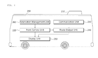
- the electric bus 200 includes a battery exchange hole 210, a front camera unit 220, a communication unit 230, a route output unit 240, a display unit 250, and a reservation management unit 260.
- the battery exchange hole 210 disposed on top of the electric bus 200 is a hole, through which the discharged battery is removed, and the charged battery is provided.
- the front camera unit 220 takes front images in the process of entering the battery exchange station 100 in order to exchange a battery.
- the front camera unit 220 can include either a single camera or a plurality of cameras for taking front images.
- the camera is placed on front of the electric bus 200, so that the camera can take images of front roads and close objects while electric bus 200 runs.
- the various types of cameras, for example, CCD cameras or CMOS cameras can be applied as the front camera unit 220.
- the communication unit 230 is for communicating with the battery exchange station 100.
- the various communication methods, including CDMA can be applied as the communication unit 230.
- the communication unit 230 receives information about the battery exchange unit 110, which is allocated by the exchange-position allocation unit 120 of the battery exchange station 100, and information about position of the allocated battery exchange unit 110, which is transmitted from the position-information providing unit 130.
- the information received through the communication unit 230 is used as basis of outputting a predicted driving route for reaching exactly below a battery exchange point.
- the route output unit 240 outputs the predicted driving route for reaching an exact point below the battery exchange unit 110 in which the battery exchange performs, based on the front images taken by the front camera unit 220 and the position-information of the battery exchange unit 110 received through the communication units 230. That is, the route output unit 240 outputs the predicted driving route, which is to guide the electric bus 200 to the point where the battery exchange can performs, with battery exchange hole 210 is connected with the battery exchange unit 110.
- the route output unit 240 outputs the predicted driving route based on the information about surroundings and close objects having potential to affect the electric bus 200, which is obtained by analyzing the front images, and also based on the distance to the battery exchange unit 110 obtained by position-information of the battery exchange unit 110. At this time, the route output unit 240 could also consider information about state of gears, angle of gears, speed of the vehicle, height of the vehicle, and so on.
- the route output unit 240 outputs the predicted driving route which is to guide the electric bus 200 to the battery exchange unit 110 allocated by the exchange-position allocation unit 120.
- the display unit 250 displays the predicted driving route outputted by the route output unit 240.
- the predicted driving route is displayed superimposed on the front images taken by the front camera unit 220.
- FIG. 5 is an example of a screen displayed on a display unit 250 of the electric bus 200 according to an exemplary embodiment of the present invention.
- the front images of the electric bus 200 and the predicted driving route which is to guide the electric bus 200 to the point below the battery exchange unit 110 in which the battery exchange performs are displayed on the display unit 250, superimposed each other.
- the display unit 250 can also displays distance remained to the battery exchange unit 110 in which the battery exchange performs, and recommended speed of vehicle at each section of the predicted driving route, which is outputted based on the distance remained.
- the electric bus 200 could further include the reservation management unit 260.
- the reservation management unit 260 stores information of reservations like existence of the reservation for battery change, reservation time, and so on.
- the reservation management unit 260 checks whether the reservation for battery exchange exists. Only when the reservation exists, that is, only when the electric bus 200 enters the battery exchange station 100 for exchanging the battery, the reservation management unit 260 controls the front camera unit 220 to take the front images.
- the route output unit 240 predicts the driving route, thereby reducing the load of communication and power consumption caused by outputting the predicted driving routed, and so on.
- the electric bus 200 could raise the alarm for a driver, in case that the electric bus 200 is running beyond the pre-determined margin of error from the predicted driving route outputted by the route output unit 240. Then, the driver can modify the driving route according to the predicted driving route.
Landscapes
- Engineering & Computer Science (AREA)
- Power Engineering (AREA)
- Mechanical Engineering (AREA)
- Transportation (AREA)
- Life Sciences & Earth Sciences (AREA)
- Sustainable Development (AREA)
- Sustainable Energy (AREA)
- Remote Sensing (AREA)
- Radar, Positioning & Navigation (AREA)
- Automation & Control Theory (AREA)
- Physics & Mathematics (AREA)
- General Physics & Mathematics (AREA)
- Arrangement Or Mounting Of Propulsion Units For Vehicles (AREA)
- Electric Propulsion And Braking For Vehicles (AREA)
- Vehicle Cleaning, Maintenance, Repair, Refitting, And Outriggers (AREA)
- Traffic Control Systems (AREA)
- Charge And Discharge Circuits For Batteries Or The Like (AREA)
- Secondary Cells (AREA)
- Navigation (AREA)
Abstract
Description
- This application claims priority under 35 U.S.C. §119 to Korean Patent Application No.
10-2012-0010005 filed on Jan 31, 2012 - The present invention relates to an electric bus and an electric bus battery exchange system, and more particularly, relates to the electric bus with an exchangeable battery and the electric bus battery exchange system that exchanges a discharged battery for a charged battery.
- An electric bus refers to a bus powered by electric energy. The electric bus has an eco-friendly characteristic that does not emit harmful gases, compared with existing automobiles using fossil fuels. Thus, the research and commercialization of the electric bus is speeding up further.
- For example, Seoul city has started the world's first electric bus since 2010, and is planning to expand the electric bus until 2014.
- The electric buses that are being currently commercialized have a short mileage with one charge, so it is inevitable that they should stop by several battery exchange stations to get electric energy. However, stopping by the battery exchange station causes inconvenience to passengers, because it takes 30 minutes to charge a battery with current technology. Therefore, the electric buses are obliged to take a short route in order to not stop by the battery exchange station, or take only a flat route.
- To solve above-mentioned problem, this applicant have proposed a battery exchange system that exchanges a discharged battery for a pre-charged battery. For instance,
KR patent applications No.2011-32024 2011-34994 2011-52913 - As mentioned above, when the battery is swapped through the hole positioned on top of the electric bus for battery exchange, it is necessary that the electric bus is positioned at exact place matched with a swapping point which is positioned above in order to exchange battery in a short time.
- Therefore, this applicant proposes an electric bus and a battery exchange system that guides the electric bus to be positioned exactly at place matched with the swapping point without any equipment disturbing the route.
- The present invention is invented based on the above description, and an embodiment of the present invention is to provide an electric bus and an electric bus battery exchange system that guide the electric bus to be positioned exactly at place which is matched with the swapping point without any equipment disturbing the route.
- To achieve the embodiment of the present invention, provided is an electric bus, including: a battery exchange hole disposed on top of the electric bus for exchanging a discharged battery for a charged battery by being connected to a battery exchange unit of a battery exchange station; a front camera unit taking front images in the process of entering the battery exchange station for battery exchange; a communication unit for receiving position information of the battery exchange unit from the battery exchange station; a route output unit outputting a predicted driving route for reaching a swapping point below the battery exchange unit based on the front images taken by the front camera unit and the position information of the battery exchange unit; and a display unit displaying the predicted driving route outputted by the route output unit, superimposed on the front images taken by the front camera unit.
- The front camera unit could take front images only when a reservation of battery exchange exists, thereby reducing power consumption.
- To achieve the embodiment of the present invention, provided is an electric bus battery exchange system comprising: a battery exchange station exchanging a discharged battery for a charged battery and comprising a battery exchange unit and a position information providing unit, wherein the battery exchange unit is projected out to be connected with a battery exchange hole positioned on top of the electric bus, and wherein the position information providing unit provides position information of the battery exchange unit to the electric bus; and an electric bus taking front images in the process of entering the battery exchange station for battery exchange, and outputting a predicted driving route for reaching a swapping point below the battery exchange unit based on the front images and the position information of the battery exchange unit.
- The battery exchange station could comprise the plurality of battery exchange units, and further could comprise an exchange-position allocation unit selecting among the plurality of battery exchange units and allocating selected battery exchange unit to the electric bus as a position for exchanging the battery, and the electric bus outputs the predicted driving route for being positioned exactly below the battery exchange unit allocated by the exchange-position allocation unit.
- The exchange-position allocation unit could reallocate one of the battery exchange unit among the plurality of battery exchange units by selecting by itself or being selected by the electric bus, in case that it is impossible for the electric bus to reach below the allocated battery exchange unit due to other electric buses being positioned below the allocated battery exchange, thereby obtaining the effectiveness.
- The battery exchange station could further comprise a move-request unit, and the move-request unit transmits a signal for asking other electric buses to move away from the battery exchange unit, in case that it is impossible for the electric bus to reach below the allocated battery exchange unit due to the other electric buses being positioned below the allocated battery exchange unit.
- According to the present invention takes front images when an electric bus enters a battery exchange station, and provides a predicted driving route which is for guiding the electric bus to a battery exchange point based on the front images. Therefore, the electric bus can reach exactly the battery exchange point.
-
-
FIG. 1 andFIG. 2 are schematic views showing an electric bus battery exchange system according to an exemplary embodiment of the present invention; -
FIG. 3 is a block diagram showing the electric bus battery exchange system according to an exemplary embodiment; -
FIG. 4 is a block diagram showing the electric bus according to an exemplary embodiment; and -
FIG. 5 is an example of a screen displayed on a display unit of the electric bus according to an exemplary embodiment of the present invention. - The foregoing and other features and advantages of the inventive concepts will be apparent from the more particular description of preferred embodiments of the inventive concepts, as illustrated in the accompanying drawings in which like reference characters refer to the same parts throughout the different views. The drawings are not necessarily to scale, emphasis instead being placed upon illustrating the principles of the inventive concepts. In the drawings:
-
FIG. 1 andFIG. 2 are schematic views showing an electric bus battery exchange system according to an exemplary embodiment of the present invention. - As shown in
FIG. 1 andFIG. 2 , the electric bus battery exchange system according to the present invention includes abattery exchange station 100 and anelectric bus 200. - The
battery exchange station 100 is a structure where swapping operation is performed. When theelectric bus 200 enters thebattery exchange station 100, thebattery exchange station 100 exchanges a discharged battery for a charged battery. Thebattery exchange station 100 provides information about position of battery swapping point so that theelectric bus 200 can reach the battery swapping point. - The
battery exchange station 100 is not restricted to its particular structure or shape. Thebattery exchange station 100 can have various structures or shapes on the condition that thebattery exchange station 100 enables theelectric bus 200 to get in or get out conveniently and the battery exchange operation can be performed. According to the exemplary embodiment, thebattery exchange station 100 is configured to have a vertical body perpendicular to a road and a horizontal body extended from top of the vertical body to the road as shown inFIG. 1 andFIG. 2 . Thus, thebattery exchange station 100 is able to exchange batteries in spite of bad weather. - The
electric bus 200 takes front images in the process of entering thebattery exchange station 100 for battery exchange, and outputs a predicted driving route for reaching the battery swapping point based on the front images and the position information transmitted from thebattery exchange station 100. - Hereinafter, with reference to
FIG. 3 andFIG. 4 , thebattery exchange station 100 and theelectric bus 200 will be explained more in detail. -
FIG. 3 is a block diagram showing the electric bus battery exchange system according to an exemplary embodiment. - As shown in
FIG. 3 , thebattery exchange station 100 includes abattery exchange unit 110, an exchange-position allocation unit 120, and a position-information providing unit 130. - The
battery exchange unit 110 is a region in which battery exchange is practically performed. Thebattery exchange unit 110 is connected with a hole for battery exchange positioned on top of theelectric bus 200 and exchanges the discharged battery for the charged battery through the hole. To achieve this, thebattery exchange unit 110 is projected out to be connected with the hole positioned on top of the electric bus, and includes battery exchange robots for removal or installation of battery, which is not shown. Thebattery exchange station 100 can include the plurality ofbattery exchange units 110, which can be helpful to save time by providing charged batteries to the severalelectric buses 200 at the same time. - The exchange-
position allocation unit 120 selects one among the plurality ofbattery exchange units 110 and allocates to theelectric bus 200, in case that thebattery exchange station 100 includes the plurality ofbattery exchange units 110. To achieve this, the exchange-position allocation unit 120 stores information about battery-exchange-state of each of thebattery exchange units 110, which is helpful to minimize the waiting time for battery exchange and enables thebattery exchange station 100 to manage effectively by allocating thebattery exchange unit 110 relatively easy to access. - The exchange-
position allocation unit 120 can reallocate thebattery exchange unit 110, in case that theelectric bus 200 is not able to reach the pre-allocatedbattery exchange unit 110. For example, it is need to be reallocated in case that otherelectric bus 200 which are not allocated or people are positioning below the allocatedbattery exchange unit 110, or the allocatedbattery exchange unit 110 needs to be repaired. In this case, the exchange-position allocation unit 120 can reallocate by selecting one among the plurality ofbattery exchange units 110 by itself. The exchange-position allocation unit 120 can also reallocate thebattery exchange unit 110, which is selected by theelectric bus 200, after analyzing whether the selectedbattery exchange unit 110 is able to be accessed. To achieve this, thebattery exchange station 100 can include sensors like image sensors or infrared sensors for detecting the presence ofelectric buses 200 or people below thebattery exchange units 110. - The position-information providing unit 130 transmits position-information of the
battery exchange unit 110 to theelectric bus 200. The position-information providing unit 130 transmits the position-information of thebattery exchange unit 110, which is allocated by the exchange-position allocation unit 120, in case that thebattery exchange station 100 includes the plurality ofbattery exchange units 110. The position-information providing unit 130 includes communication means for communicating with theelectric bus 200 and stores the position information of thebattery exchange units 110. - The electric bus
battery exchange station 100 according to the exemplary embodiment of the present invention could further include a move-request unit 140 transmitting a signal for asking otherelectric buses 200 to move away from thebattery exchange unit 110, current position. The move-request unit 140 transmits the signal to the otherelectric buses 200, in case that it is impossible for theelectric bus 200 to access to the allocatedbattery exchange unit 110 because the otherelectric buses 200 are being positioned below the allocatedbattery exchange unit 110. When the otherelectric buses 200 move away from the allocatedbattery exchange unit 110 in response to the request of the move-request unit 140, theelectric bus 200 could access the allocatedbattery exchange unit 110. On the other hand, in case that the otherelectric buses 200 cannot move away somewhere, the exchange-position allocation unit 120 reallocates thebattery exchange unit 110. -
FIG. 4 a block diagram showing theelectric bus 200 according to an exemplary embodiment. - As shown in
FIG. 4 , theelectric bus 200 according to the exemplary embodiment includes abattery exchange hole 210, afront camera unit 220, acommunication unit 230, aroute output unit 240, adisplay unit 250, and areservation management unit 260. - The
battery exchange hole 210 disposed on top of theelectric bus 200 is a hole, through which the discharged battery is removed, and the charged battery is provided. - The
front camera unit 220 takes front images in the process of entering thebattery exchange station 100 in order to exchange a battery. Thefront camera unit 220 can include either a single camera or a plurality of cameras for taking front images. The camera is placed on front of theelectric bus 200, so that the camera can take images of front roads and close objects whileelectric bus 200 runs. The various types of cameras, for example, CCD cameras or CMOS cameras can be applied as thefront camera unit 220. - The
communication unit 230 is for communicating with thebattery exchange station 100. The various communication methods, including CDMA can be applied as thecommunication unit 230. Thecommunication unit 230 receives information about thebattery exchange unit 110, which is allocated by the exchange-position allocation unit 120 of thebattery exchange station 100, and information about position of the allocatedbattery exchange unit 110, which is transmitted from the position-information providing unit 130. The information received through thecommunication unit 230 is used as basis of outputting a predicted driving route for reaching exactly below a battery exchange point. - The
route output unit 240 outputs the predicted driving route for reaching an exact point below thebattery exchange unit 110 in which the battery exchange performs, based on the front images taken by thefront camera unit 220 and the position-information of thebattery exchange unit 110 received through thecommunication units 230. That is, theroute output unit 240 outputs the predicted driving route, which is to guide theelectric bus 200 to the point where the battery exchange can performs, withbattery exchange hole 210 is connected with thebattery exchange unit 110. Theroute output unit 240 outputs the predicted driving route based on the information about surroundings and close objects having potential to affect theelectric bus 200, which is obtained by analyzing the front images, and also based on the distance to thebattery exchange unit 110 obtained by position-information of thebattery exchange unit 110. At this time, theroute output unit 240 could also consider information about state of gears, angle of gears, speed of the vehicle, height of the vehicle, and so on. - In case that the
battery exchange station 100 includes the plurality ofbattery exchange units 110, theroute output unit 240 outputs the predicted driving route which is to guide theelectric bus 200 to thebattery exchange unit 110 allocated by the exchange-position allocation unit 120. - The
display unit 250 displays the predicted driving route outputted by theroute output unit 240. The predicted driving route is displayed superimposed on the front images taken by thefront camera unit 220. -
FIG. 5 is an example of a screen displayed on adisplay unit 250 of theelectric bus 200 according to an exemplary embodiment of the present invention. - As shown in
FIG. 5 , the front images of theelectric bus 200 and the predicted driving route which is to guide theelectric bus 200 to the point below thebattery exchange unit 110 in which the battery exchange performs are displayed on thedisplay unit 250, superimposed each other. At this time, thedisplay unit 250 can also displays distance remained to thebattery exchange unit 110 in which the battery exchange performs, and recommended speed of vehicle at each section of the predicted driving route, which is outputted based on the distance remained. - The
electric bus 200 according to the exemplary embodiment of the present invention could further include thereservation management unit 260. Thereservation management unit 260 stores information of reservations like existence of the reservation for battery change, reservation time, and so on. Thereservation management unit 260 checks whether the reservation for battery exchange exists. Only when the reservation exists, that is, only when theelectric bus 200 enters thebattery exchange station 100 for exchanging the battery, thereservation management unit 260 controls thefront camera unit 220 to take the front images. As a result, in case that thebattery exchange station 100 is also used as a bus stop, only when theelectric bus 200 enters for battery exchange, theroute output unit 240 predicts the driving route, thereby reducing the load of communication and power consumption caused by outputting the predicted driving routed, and so on. - The above description is suggested only as an exemplary embodiment for realizing the
electric bus 200 and the electric bus battery exchange system according to the present invention described above. The present invention is not limited to the exemplary embodiment. For example, theelectric bus 200 could raise the alarm for a driver, in case that theelectric bus 200 is running beyond the pre-determined margin of error from the predicted driving route outputted by theroute output unit 240. Then, the driver can modify the driving route according to the predicted driving route. - It will be apparent that various changes and modifications may be made by those skilled in the art without deviating from the basic concept and scope of the invention as set forth in the appended claims.
Claims (6)
- An electric bus comprising:a battery exchange hole disposed on top of the electric bus for exchanging a discharged battery for a charged battery by being connected to a battery exchange unit of a battery exchange station;a front camera unit taking front images in the process of entering the battery exchange station for battery exchange;a communication unit for receiving position information of the battery exchange unit from the battery exchange station;a route output unit outputting a predicted driving route for reaching a swapping point below the battery exchange unit based on the front images taken by the front camera unit and the position information of the battery exchange unit; anda display unit displaying the predicted driving route outputted by the route output unit, superimposed on the front images taken by the front camera unit.
- The electric bus of claim 1 wherein the front camera unit takes front images only when a reservation of battery exchange exists.
- An electric bus battery exchange system comprising:a battery exchange station exchanging a discharged battery for a charged battery and comprising a battery exchange unit and a position-information providing unit, wherein the battery exchange unit is projected out to be connected with a battery exchange hole positioned on top of the electric bus, and wherein the position-information providing unit provides position information of the battery exchange unit to the electric bus; andan electric bus taking front images in the process of entering the battery exchange station for battery exchange, and outputting a predicted driving route for reaching a swapping point below the battery exchange unit based on the front images and the position information of the battery exchange unit.
- The electric bus battery exchange system of claim 3,
wherein the battery exchange station comprises the plurality of battery exchange units, and further comprises an exchange-position allocation unit selecting among the plurality of battery exchange units and allocating selected battery exchange unit to the electric bus as a position for exchanging the battery, and
wherein the electric bus outputs the predicted driving route for being positioned exactly below the battery exchange unit allocated by the exchange-position allocation unit. - The electric bus battery exchange system of claim 4,
wherein the exchange-position allocation unit reallocates one of the battery exchange unit among the plurality of battery exchange units by selecting by itself or being selected by the electric bus, in case that it is impossible for the electric bus to reach below the allocated battery exchange unit due to other electric buses being positioned below the allocated battery exchange unit. - The electric bus battery exchange system of claim 4,
wherein the battery exchange station further comprises a move-request unit, and wherein the move-request unit transmits a signal for asking other electric buses to move away from the battery exchange unit, in case that it is impossible for the electric bus to reach below the allocated battery exchange unit due to the other electric buses being positioned below the allocated battery exchange.
Applications Claiming Priority (1)
| Application Number | Priority Date | Filing Date | Title |
|---|---|---|---|
| KR1020120010005A KR101245566B1 (en) | 2012-01-31 | 2012-01-31 | Electric bus and electric bus battery exchanging system |
Publications (2)
| Publication Number | Publication Date |
|---|---|
| EP2623362A2 true EP2623362A2 (en) | 2013-08-07 |
| EP2623362A3 EP2623362A3 (en) | 2017-04-26 |
Family
ID=46397054
Family Applications (1)
| Application Number | Title | Priority Date | Filing Date |
|---|---|---|---|
| EP12173940.3A Withdrawn EP2623362A3 (en) | 2012-01-31 | 2012-06-27 | Electric bus and electric bus battery exchange system |
Country Status (6)
| Country | Link |
|---|---|
| US (2) | US8862391B2 (en) |
| EP (1) | EP2623362A3 (en) |
| JP (1) | JP5449465B2 (en) |
| KR (1) | KR101245566B1 (en) |
| CN (1) | CN103223924B (en) |
| CA (1) | CA2781514C (en) |
Cited By (2)
| Publication number | Priority date | Publication date | Assignee | Title |
|---|---|---|---|---|
| GB2568022A (en) * | 2017-09-11 | 2019-05-08 | John Hill David | Concept for interchangeable power source(s) for electric vehicles |
| EE202300004A (en) * | 2023-01-12 | 2024-08-15 | Eesti Maaülikool | Device for changing and charging the battery of the agricultural robot |
Families Citing this family (23)
| Publication number | Priority date | Publication date | Assignee | Title |
|---|---|---|---|---|
| DK2694424T3 (en) * | 2011-04-06 | 2015-09-07 | Terex Mhps Gmbh | Portal vows with electric drive |
| JP5563626B2 (en) * | 2012-06-29 | 2014-07-30 | 国民大学校産学協力団 | Battery exchange type electric vehicle charging station system |
| KR101510147B1 (en) | 2013-07-19 | 2015-04-08 | 국민대학교산학협력단 | Guide system for electric bus in battery exchange station |
| KR101483294B1 (en) * | 2013-07-19 | 2015-01-15 | 국민대학교산학협력단 | Apparatus and method for adjusting position of electric bus battery exchanger |
| US9688252B2 (en) | 2014-04-23 | 2017-06-27 | Tesla, Inc. | Battery swapping system and techniques |
| FR3026355B1 (en) | 2014-09-30 | 2017-12-29 | Bluetram | METHOD AND SYSTEM FOR ASSISTING POSITIONING OF AN ELECTRIC VEHICLE IN RELATION TO A RECHARGE STATION, RECHARGING STATION AND ELECTRIC VEHICLE IMPLEMENTING SAID METHOD |
| BR112017022791A2 (en) | 2015-04-22 | 2018-07-17 | Ahrens Jason | vehicle power exchange system, vehicle on-board vehicle system and vehicle power exchange method |
| CN106064568A (en) * | 2015-04-23 | 2016-11-02 | 苏州宝时得电动工具有限公司 | Electric vehicle energy supplement system, method and apparatus |
| KR101754975B1 (en) | 2015-11-11 | 2017-07-19 | 주식회사 티원 | apparatus for controlling position of battery |
| JP6766343B2 (en) | 2015-11-17 | 2020-10-14 | オムロン株式会社 | Battery reservation device |
| JP6582909B2 (en) * | 2015-11-17 | 2019-10-02 | オムロン株式会社 | Battery reservation device and battery reservation method |
| JP6724343B2 (en) * | 2015-11-17 | 2020-07-15 | オムロン株式会社 | Reservation management device, reservation management system, and reservation management method |
| JP6597218B2 (en) * | 2015-11-17 | 2019-10-30 | オムロン株式会社 | Battery reservation device and battery reservation method |
| CN107310534A (en) * | 2017-06-21 | 2017-11-03 | 广东高标电子科技有限公司 | A kind of battery change method of electric car and mobile electrical changing station and server |
| CN107310412A (en) * | 2017-06-21 | 2017-11-03 | 广东高标电子科技有限公司 | A kind of electric car changes method for electrically, device and server and mobile electrical changing station |
| CN107770497A (en) * | 2017-11-03 | 2018-03-06 | 重庆立洋机电设备制造有限公司 | Battery type mobile monitoring robot and its monitoring system and method |
| WO2019190556A1 (en) | 2018-03-30 | 2019-10-03 | Cummins Inc. | Vehicle to vehicle communication |
| CN109367524B (en) * | 2018-12-03 | 2023-04-25 | 黄河科技学院 | Automatic battery replacement method for electric vehicles |
| EP3726241A1 (en) * | 2019-04-19 | 2020-10-21 | Siemens Mobility GmbH | Method and system for locating an object |
| CN114683910B (en) * | 2020-12-31 | 2023-10-31 | 奥动新能源汽车科技有限公司 | Battery replacement prompt method, system, equipment and readable storage medium |
| CN113428044B (en) * | 2021-06-21 | 2023-06-09 | 深圳先阳新能源技术有限公司 | A replacement system for a spare battery pack on a vehicle roof |
| US11400829B1 (en) | 2021-07-13 | 2022-08-02 | Popion Mobility Inc. | Methods and systems for battery-vehicle interface solutions for supporting use of swappable batteries in electric vehicles |
| KR102760984B1 (en) * | 2023-12-19 | 2025-02-03 | 주식회사 펌프킨 | Ground leveling device that improves the contact efficiency of the pantograph and contact bar |
Citations (3)
| Publication number | Priority date | Publication date | Assignee | Title |
|---|---|---|---|---|
| KR20110032024A (en) | 2009-09-22 | 2011-03-30 | 엘지전자 주식회사 | Method of processing remote control signal, transmitting device, receiving device and display device using same |
| KR20110034994A (en) | 2009-09-29 | 2011-04-06 | 주식회사 캐프 | Multi Adapter for Car Wiper |
| KR20110052913A (en) | 2009-11-13 | 2011-05-19 | 이운형 | Sensor network system for emergency call |
Family Cites Families (17)
| Publication number | Priority date | Publication date | Assignee | Title |
|---|---|---|---|---|
| JP3182689B2 (en) * | 1999-05-18 | 2001-07-03 | 矢崎化工株式会社 | Automatic battery changer for unmanned vehicles |
| JP2003102110A (en) * | 2001-09-25 | 2003-04-04 | Sanyo Electric Co Ltd | Battery replacement system for traveling electric vehicle |
| JP2004066889A (en) * | 2002-08-02 | 2004-03-04 | Mitsubishi Fuso Truck & Bus Corp | Battery unit mounting structure |
| CN1261319C (en) * | 2004-11-11 | 2006-06-28 | 北京电巴科技有限公司 | An electric bus system |
| JP2006331405A (en) * | 2005-04-21 | 2006-12-07 | Ntt Facilities Inc | Secondary battery supply system and secondary battery supply method |
| FR2892069B1 (en) * | 2005-10-17 | 2014-07-18 | Pvi | RECHARGING STATION AND ASSOCIATED ELECTRIC VEHICLE |
| JP2008309529A (en) * | 2007-06-12 | 2008-12-25 | Panasonic Corp | NAVIGATION DEVICE, NAVIGATION METHOD, AND NAVIGATION PROGRAM |
| GB2460500A (en) * | 2007-12-24 | 2009-12-09 | Yaron Mayer | Electric cars, electric car batteries, and infrastructures for recharging electric cars |
| CA2648972A1 (en) * | 2007-12-24 | 2009-06-24 | Yaron Mayer | System and method for improved electric cars and/or electric car batteries and/or improved infrastructures for recharging electric cars |
| CN201189858Y (en) * | 2008-03-21 | 2009-02-04 | 陈玉启 | Urban low cost pure electric public transport system |
| JP5334604B2 (en) * | 2009-01-28 | 2013-11-06 | 中国電力株式会社 | Electric vehicle charging system |
| KR101197349B1 (en) * | 2009-03-17 | 2012-11-05 | 알리스 에이알케이 코. 엘티디. | Method of power management for plug-in hybrid and electric vehicle |
| JP5377119B2 (en) * | 2009-07-02 | 2013-12-25 | トヨタ自動車株式会社 | Parking support system and control method for parking support system |
| DE102009045448B4 (en) * | 2009-08-20 | 2025-09-04 | Proton Motor Fuel Cell Gmbh | Vehicle for driving in stages with an electric motor and a battery and method for driving a vehicle |
| JP5494130B2 (en) * | 2010-03-31 | 2014-05-14 | アイシン・エィ・ダブリュ株式会社 | VEHICLE CHARGE SUPPORT DEVICE, VEHICLE CHARGE SUPPORT METHOD, AND COMPUTER PROGRAM |
| CN101823473B (en) * | 2010-05-31 | 2012-08-15 | 团国兴 | Mobile battery change system for electric automobile by utilizing mobile battery change vehicle |
| JP2012008020A (en) * | 2010-06-25 | 2012-01-12 | Clarion Co Ltd | On-vehicle device |
-
2012
- 2012-01-31 KR KR1020120010005A patent/KR101245566B1/en active Active
- 2012-06-22 CA CA2781514A patent/CA2781514C/en active Active
- 2012-06-27 EP EP12173940.3A patent/EP2623362A3/en not_active Withdrawn
- 2012-06-29 JP JP2012147549A patent/JP5449465B2/en not_active Expired - Fee Related
- 2012-07-01 US US13/539,482 patent/US8862391B2/en active Active
- 2012-07-05 CN CN201210232786.0A patent/CN103223924B/en active Active
-
2014
- 2014-09-22 US US14/492,640 patent/US9026357B2/en active Active
Patent Citations (3)
| Publication number | Priority date | Publication date | Assignee | Title |
|---|---|---|---|---|
| KR20110032024A (en) | 2009-09-22 | 2011-03-30 | 엘지전자 주식회사 | Method of processing remote control signal, transmitting device, receiving device and display device using same |
| KR20110034994A (en) | 2009-09-29 | 2011-04-06 | 주식회사 캐프 | Multi Adapter for Car Wiper |
| KR20110052913A (en) | 2009-11-13 | 2011-05-19 | 이운형 | Sensor network system for emergency call |
Cited By (3)
| Publication number | Priority date | Publication date | Assignee | Title |
|---|---|---|---|---|
| GB2568022A (en) * | 2017-09-11 | 2019-05-08 | John Hill David | Concept for interchangeable power source(s) for electric vehicles |
| EE202300004A (en) * | 2023-01-12 | 2024-08-15 | Eesti Maaülikool | Device for changing and charging the battery of the agricultural robot |
| EE05874B1 (en) * | 2023-01-12 | 2024-10-15 | Eesti Maaülikool | Device for changing and charging the battery of the agricultural robot |
Also Published As
| Publication number | Publication date |
|---|---|
| US20130197803A1 (en) | 2013-08-01 |
| CN103223924B (en) | 2015-09-09 |
| US8862391B2 (en) | 2014-10-14 |
| JP5449465B2 (en) | 2014-03-19 |
| US9026357B2 (en) | 2015-05-05 |
| JP2013158229A (en) | 2013-08-15 |
| KR101245566B1 (en) | 2013-03-22 |
| CA2781514A1 (en) | 2013-07-31 |
| EP2623362A3 (en) | 2017-04-26 |
| CA2781514C (en) | 2015-08-11 |
| CN103223924A (en) | 2013-07-31 |
| US20150012212A1 (en) | 2015-01-08 |
Similar Documents
| Publication | Publication Date | Title |
|---|---|---|
| US8862391B2 (en) | Electric bus and electric bus battery exchange system | |
| CA2781543C (en) | Electric bus battery exchange station | |
| CN110015113A (en) | Vehicular charging control device and method and vehicle charging system | |
| CN203721041U (en) | Parking guiding system | |
| CN104157164A (en) | Parking guidance system | |
| CN107633694A (en) | A kind of parking management system of pilotless automobile | |
| US11500381B2 (en) | Stopping position control device, stopping position control method, and computer program for stopping position control | |
| JP2011214895A (en) | Device and method for guiding vehicle change | |
| JP2015094695A (en) | Electric vehicle driving support system | |
| JP7468489B2 (en) | Parking lot management system, parking lot management method and program | |
| CN110544391A (en) | Vehicle-mounted system, parking lot management system, auxiliary parking system and method | |
| JP2023011180A (en) | Non-contact charger and non-contact charging method | |
| CN105809769A (en) | Panorama image automobile data recorder connected through WiFi | |
| KR101402668B1 (en) | Electric Bus Battery Exchange Station | |
| JP2021162959A (en) | Accommodation area management apparatus | |
| CN108510765A (en) | A kind of multichannel bus station stop parking stall distribution method | |
| CN105280013A (en) | Garage management system and management method thereof | |
| JP7574750B2 (en) | Vehicles and charging systems | |
| CN202838455U (en) | Intelligent leading system of highway toll station | |
| JP7798049B2 (en) | Server device | |
| US12447989B2 (en) | Determination device | |
| JP2025026115A (en) | SERVER DEVICE, SYSTEM, AND SYSTEM OPERATION METHOD | |
| CN117523908A (en) | Method and system for replacing parking space of vehicle | |
| KR20250172022A (en) | System and apparatus for providing information about parking spaces available to electric vehicles for being charged | |
| CN118627790A (en) | A parking area determination and parking method and device |
Legal Events
| Date | Code | Title | Description |
|---|---|---|---|
| PUAI | Public reference made under article 153(3) epc to a published international application that has entered the european phase |
Free format text: ORIGINAL CODE: 0009012 |
|
| 17P | Request for examination filed |
Effective date: 20120627 |
|
| AK | Designated contracting states |
Kind code of ref document: A2 Designated state(s): AL AT BE BG CH CY CZ DE DK EE ES FI FR GB GR HR HU IE IS IT LI LT LU LV MC MK MT NL NO PL PT RO RS SE SI SK SM TR |
|
| AX | Request for extension of the european patent |
Extension state: BA ME |
|
| PUAL | Search report despatched |
Free format text: ORIGINAL CODE: 0009013 |
|
| AK | Designated contracting states |
Kind code of ref document: A3 Designated state(s): AL AT BE BG CH CY CZ DE DK EE ES FI FR GB GR HR HU IE IS IT LI LT LU LV MC MK MT NL NO PL PT RO RS SE SI SK SM TR |
|
| AX | Request for extension of the european patent |
Extension state: BA ME |
|
| RIC1 | Information provided on ipc code assigned before grant |
Ipc: B60L 11/18 20060101AFI20170323BHEP Ipc: B60S 5/06 20060101ALI20170323BHEP Ipc: B60L 3/12 20060101ALI20170323BHEP Ipc: G01C 21/34 20060101ALI20170323BHEP |
|
| RBV | Designated contracting states (corrected) |
Designated state(s): AL AT BE BG CH CY CZ DE DK EE ES FI FR GB GR HR HU IE IS IT LI LT LU LV MC MK MT NL NO PL PT RO RS SE SI SK SM TR |
|
| 17Q | First examination report despatched |
Effective date: 20181025 |
|
| RIC1 | Information provided on ipc code assigned before grant |
Ipc: B60L 50/60 20190101ALI20190918BHEP Ipc: B60L 3/12 20060101ALI20190918BHEP Ipc: B60L 53/65 20190101ALI20190918BHEP Ipc: B60L 53/35 20190101ALI20190918BHEP Ipc: B60L 53/80 20190101AFI20190918BHEP |
|
| GRAP | Despatch of communication of intention to grant a patent |
Free format text: ORIGINAL CODE: EPIDOSNIGR1 |
|
| INTG | Intention to grant announced |
Effective date: 20191218 |
|
| STAA | Information on the status of an ep patent application or granted ep patent |
Free format text: STATUS: THE APPLICATION IS DEEMED TO BE WITHDRAWN |
|
| 18D | Application deemed to be withdrawn |
Effective date: 20200603 |