EP2622716B1 - Magnetic rotor having inset bridges to promote cooling - Google Patents
Magnetic rotor having inset bridges to promote cooling Download PDFInfo
- Publication number
- EP2622716B1 EP2622716B1 EP11831282.6A EP11831282A EP2622716B1 EP 2622716 B1 EP2622716 B1 EP 2622716B1 EP 11831282 A EP11831282 A EP 11831282A EP 2622716 B1 EP2622716 B1 EP 2622716B1
- Authority
- EP
- European Patent Office
- Prior art keywords
- bridges
- rotor
- spokes
- lamination
- rotor arrangement
- Prior art date
- Legal status (The legal status is an assumption and is not a legal conclusion. Google has not performed a legal analysis and makes no representation as to the accuracy of the status listed.)
- Active
Links
Images


Classifications
-
- H—ELECTRICITY
- H02—GENERATION; CONVERSION OR DISTRIBUTION OF ELECTRIC POWER
- H02K—DYNAMO-ELECTRIC MACHINES
- H02K1/00—Details of the magnetic circuit
- H02K1/06—Details of the magnetic circuit characterised by the shape, form or construction
- H02K1/22—Rotating parts of the magnetic circuit
- H02K1/32—Rotating parts of the magnetic circuit with channels or ducts for flow of cooling medium
-
- H—ELECTRICITY
- H02—GENERATION; CONVERSION OR DISTRIBUTION OF ELECTRIC POWER
- H02K—DYNAMO-ELECTRIC MACHINES
- H02K1/00—Details of the magnetic circuit
- H02K1/06—Details of the magnetic circuit characterised by the shape, form or construction
- H02K1/22—Rotating parts of the magnetic circuit
- H02K1/27—Rotor cores with permanent magnets
- H02K1/2706—Inner rotors
- H02K1/272—Inner rotors the magnetisation axis of the magnets being perpendicular to the rotor axis
- H02K1/274—Inner rotors the magnetisation axis of the magnets being perpendicular to the rotor axis the rotor consisting of two or more circumferentially positioned magnets
- H02K1/2753—Inner rotors the magnetisation axis of the magnets being perpendicular to the rotor axis the rotor consisting of two or more circumferentially positioned magnets the rotor consisting of magnets or groups of magnets arranged with alternating polarity
- H02K1/276—Magnets embedded in the magnetic core, e.g. interior permanent magnets [IPM]
- H02K1/2766—Magnets embedded in the magnetic core, e.g. interior permanent magnets [IPM] having a flux concentration effect
-
- H—ELECTRICITY
- H02—GENERATION; CONVERSION OR DISTRIBUTION OF ELECTRIC POWER
- H02K—DYNAMO-ELECTRIC MACHINES
- H02K1/00—Details of the magnetic circuit
- H02K1/06—Details of the magnetic circuit characterised by the shape, form or construction
- H02K1/22—Rotating parts of the magnetic circuit
- H02K1/24—Rotor cores with salient poles ; Variable reluctance rotors
- H02K1/246—Variable reluctance rotors
Definitions
- the present invention relates to an interior permanent magnet synchronous motor having a rotor configuration permitting an increased flow of air or other fluid between the rotor and a stator of the motor for improved heat transfer.
- U.S. Patent 5,051 ,634 to Overton discloses an electric motor including a steel shaft surrounded by an iron sleeve on which four permanent magnets are mounted. A banding surrounds the rotor structure to hold the magnets in place. To effect a transfer of heat from windings of the motor to the motor housing, a heat spike is added into each stator slot of the motor.
- U.S. Patent Application Publication 2008/0030108 to Trago et al. discloses a stepper motor having a rotor shaft with front and rear rotor segments disposed thereon.
- An aluminum housing and aluminum endbells conduct heat generated in the motor into a faceplate for improved performance.
- US 6 225 724 B1 discloses a motor rotor having embedded permanent magnets.
- a rotor includes a rotor core with laminated rotor core plates.
- a rotor core is made of electromagnetic steel, in which a number of slits and a number of magnetic paths are formed in a direction of a center of the rotor core. The magnets are embedded in the slits.
- US 5 491 371 discloses a lamination for a stator or rotor of an electrical machine, wherein the lamination has a series of circularly spaced protrusions projecting away from the periphery and from the main extent of the lamination, whereby a stack of laminations, at least some of which incorporate the protrusions, define fluid coolant passages adjacent the protrusions.
- JP S61 254036 A discloses a rotor provided with a magnetic pole fitted on a yoke on a rotary shaft.
- the pole is provided with a ventilation flue so that the pole surface on the rear side may be cooled more than the pole surfaces on the front side in the rotational direction of the pole.
- the ventilation flue is provided continuously in the peripheral direction on the surface of the pole, and is formed with a continuous cooled groove.
- EP 1 953 896 A1 discloses a rotor for an electric rotating machine that improves cooling performance of the rotating machine.
- Figure 1 illustrates a known interior permanent magnet rotor lamination 10, in plan view, with indentations 12 on the rotor outer diameter 13.
- the rotor lamination illustrated in Figure 1 is a single layer interior permanent magnet rotor lamination.
- Each indentation 12 is located between adjacent pairs of magnet receiving voids or orifices 14 and 16, 18 and 20, 22 and 24, and 26 and 28, and each magnet receiving void or orifice of these pairs is separated from the other such void or orifice by a thin bridge 30 of rotor lamination material.
- permanent magnets (not shown) are affixed within the voids or orifices to cooperate with windings disposed around poles of a stator, within which the rotor lamination 10 is rotatable.
- a rotor shaft (not shown) is receivable within a shaft opening 32 to impart rotational motion to the rotor.
- the present invention provides a rotor arrangement according to claim 1. Specific embodiments are defined in the dependent claims.
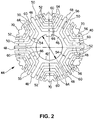
- a lamina 40 used in production of a rotor according to the present invention is shown in plan view in Figure 2 . It will be understood by those of ordinary skill in the art that the lamina 40 shown in Figure 2 is the endmost lamina of multiple (e.g., fifty) laminas joined together in a stack to produce a multilayer laminated rotor 44.
- the laminas may be stamped from sheets of steel or other suitable material.
- a rotor shaft (not shown) is receivable within a shaft opening 42 of the rotor 44 to impart rotational motion to the rotor.
- Each lamina 40 may have a unitary, one piece construction, as shown, with a solid central section 46, in which the shaft opening 42 is provided, and a multiplicity of spokes 48 extending radially outward from the solid central section 46.
- a plurality of nested ribs 50 are received between adjacent spokes 48.
- the ribs 50 and the spokes 48 are interconnected by way of outer, approximately circumferentially extending bridges 52 and inner, approximately radially extending bridges 54, so that each rotor lamina 40, as a whole, is an integral element.
- six spokes 48, at sixty degree intervals, are shown, but other numbers of spokes could be used.
- Protrusions 56 are defined at appropriate locations on opposed edges of the spokes 48 and the ribs 50. These protrusions serve to properly position permanent magnet elements (not shown) receivable within magnet receptacles 60 defined between the protrusions 56 and the outer bridges 52.
- the rotor 44 thus is formed as a multilayer IPM (interior permanent magnet) rotor, with outer bridges 52 that are inset from the outer diameter of the rotor 44.
- These bridges 52 of laminate material are not on the rotor outer diameter, as is traditional for multilayer IPM designs, but rather inset toward the inner diameter or solid central section 46 of the rotor 44.
- Insetting the bridges 52 in this way allows for recesses 64, which add significant cross- sectional area at the rotor outer diameter that is contiguous with the air or other fluid gap, within which cooling air or other fluid can flow. This area allows for a lower impedance path for fluid flow from a shaft mounted fan, and, therefore, provides improved cooling of the motor windings, which form the hottest part of the motor.
- FIG. 2 Each lamination of the rotor 44 illustrated in Figure 2 is shown with center pole tips 70 located within what otherwise would be unobstructed air channels at the rotor outer circumference.
- the center pole tips 70 are integrally formed with the rest of the lamination, and are intended to increase the average torque produced and, at the same time, minimize variations in torque, or torque "ripple.”
- Figure 3 illustrates a portion of a similar multilayer laminated rotor 44', having outer air flow channels 80 unobstructed by center pole tips 70.
- a rotor constructed from laminations 44' might have a somewhat greater degree of torque ripple, a lower average torque, or both, but would have greater cooling characteristics as well.
Landscapes
- Engineering & Computer Science (AREA)
- Power Engineering (AREA)
- Permanent Field Magnets Of Synchronous Machinery (AREA)
- Iron Core Of Rotating Electric Machines (AREA)
Description
- The present invention relates to an interior permanent magnet synchronous motor having a rotor configuration permitting an increased flow of air or other fluid between the rotor and a stator of the motor for improved heat transfer.
-
U.S. Patent 5,051 ,634 to Overton discloses an electric motor including a steel shaft surrounded by an iron sleeve on which four permanent magnets are mounted. A banding surrounds the rotor structure to hold the magnets in place. To effect a transfer of heat from windings of the motor to the motor housing, a heat spike is added into each stator slot of the motor. -
U.S. Patent Application Publication 2008/0030108 to Trago et al. discloses a stepper motor having a rotor shaft with front and rear rotor segments disposed thereon. An aluminum housing and aluminum endbells conduct heat generated in the motor into a faceplate for improved performance. -
US 6 225 724 B1 discloses a motor rotor having embedded permanent magnets. A rotor includes a rotor core with laminated rotor core plates. A rotor core is made of electromagnetic steel, in which a number of slits and a number of magnetic paths are formed in a direction of a center of the rotor core. The magnets are embedded in the slits. -
US 5 491 371 discloses a lamination for a stator or rotor of an electrical machine, wherein the lamination has a series of circularly spaced protrusions projecting away from the periphery and from the main extent of the lamination, whereby a stack of laminations, at least some of which incorporate the protrusions, define fluid coolant passages adjacent the protrusions. -
JP S61 254036 A -
EP 1 953 896 A1 discloses a rotor for an electric rotating machine that improves cooling performance of the rotating machine. -
Figure 1 illustrates a known interior permanentmagnet rotor lamination 10, in plan view, withindentations 12 on the rotorouter diameter 13. The rotor lamination illustrated inFigure 1 is a single layer interior permanent magnet rotor lamination. Eachindentation 12 is located between adjacent pairs of magnet receiving voids ororifices thin bridge 30 of rotor lamination material. In operation, permanent magnets (not shown) are affixed within the voids or orifices to cooperate with windings disposed around poles of a stator, within which therotor lamination 10 is rotatable. A rotor shaft (not shown) is receivable within a shaft opening 32 to impart rotational motion to the rotor. - The present invention provides a rotor arrangement according to claim 1. Specific embodiments are defined in the dependent claims.
-
-
Figure 1 is a plan view of a known interior permanent magnet rotor lamination. -
Figure 2 is a plan view of an interior permanent magnet rotor lamination in accordance with one embodiment of the present invention. -
Figure 3 is a plan view of part of an interior permanent magnet rotor lamination in accordance with another embodiment of the present invention. - A
lamina 40 used in production of a rotor according to the present invention is shown in plan view inFigure 2 . It will be understood by those of ordinary skill in the art that thelamina 40 shown inFigure 2 is the endmost lamina of multiple (e.g., fifty) laminas joined together in a stack to produce a multilayer laminatedrotor 44. The laminas may be stamped from sheets of steel or other suitable material. As with the known arrangement illustrated inFigure 1 , a rotor shaft (not shown) is receivable within a shaft opening 42 of therotor 44 to impart rotational motion to the rotor. - Each
lamina 40 may have a unitary, one piece construction, as shown, with a solidcentral section 46, in which theshaft opening 42 is provided, and a multiplicity ofspokes 48 extending radially outward from the solidcentral section 46. A plurality ofnested ribs 50 are received betweenadjacent spokes 48. Theribs 50 and thespokes 48 are interconnected by way of outer, approximately circumferentially extendingbridges 52 and inner, approximately radially extendingbridges 54, so that eachrotor lamina 40, as a whole, is an integral element. InFigure 2 , sixspokes 48, at sixty degree intervals, are shown, but other numbers of spokes could be used.Protrusions 56 are defined at appropriate locations on opposed edges of thespokes 48 and theribs 50. These protrusions serve to properly position permanent magnet elements (not shown) receivable withinmagnet receptacles 60 defined between theprotrusions 56 and theouter bridges 52. - The
rotor 44 thus is formed as a multilayer IPM (interior permanent magnet) rotor, withouter bridges 52 that are inset from the outer diameter of therotor 44. Thesebridges 52 of laminate material are not on the rotor outer diameter, as is traditional for multilayer IPM designs, but rather inset toward the inner diameter or solidcentral section 46 of therotor 44. Insetting thebridges 52 in this way allows forrecesses 64, which add significant cross- sectional area at the rotor outer diameter that is contiguous with the air or other fluid gap, within which cooling air or other fluid can flow. This area allows for a lower impedance path for fluid flow from a shaft mounted fan, and, therefore, provides improved cooling of the motor windings, which form the hottest part of the motor. Setting theouter bridges 52 in from the outer diameter of therotor 44, in other words, provides an increased cross-sectional area in an air gap region, which increases the airflow from a fan (not shown) and provides increased heat transfer from the winding and the rotor to the airflow, thereby cooling the motor with greater effect. Air flow, of course, will also occur throughpassages 66 remaining between themagnet receptacles 60 and the radially extendingbridges 54. - Each lamination of the
rotor 44 illustrated inFigure 2 is shown withcenter pole tips 70 located within what otherwise would be unobstructed air channels at the rotor outer circumference. Thecenter pole tips 70 are integrally formed with the rest of the lamination, and are intended to increase the average torque produced and, at the same time, minimize variations in torque, or torque "ripple."Figure 3 illustrates a portion of a similar multilayer laminated rotor 44', having outerair flow channels 80 unobstructed bycenter pole tips 70. A rotor constructed from laminations 44' might have a somewhat greater degree of torque ripple, a lower average torque, or both, but would have greater cooling characteristics as well. - The foregoing disclosure has been set forth merely to illustrate the invention and is not intended to be limiting. Modifications of the disclosed embodiments incorporating the substance of the invention may occur to persons skilled in the art, and the invention should be construed to include everything within the scope of the invention ultimately claimed.
Claims (6)
- A rotor arrangement mountable on a shaft for rotation relative to a stator of a rotary arrangement having a plurality of laminations (40) joined together to form a multilayer laminated rotor (44) with a plurality of magnet receptacles (60), each of the laminations comprising:a solid central section (46) surrounding an opening (42) within which the shaft is receivable,spokes (48) extending substantially radially outwardly from the solid central section (46),ribs (50) interposed between adjacent spokes (48),bridges (52) interconnecting the spokes (48) and ribs (50),wherein at least some of the bridges (52) are inset from an outer diameter of the lamination (40) toward the solid central section (46) to decrease fluid flow impedance and improve rotary motor cooling,wherein the bridges (52) extend approximately circumferentially and further comprising additional radially extending bridges (54) that interconnect the solid central section (46) and a plurality of the ribs (50),further comprising air flow passages (66) between the magnet receptacles (60) and the radially extending bridges (54).
- The rotor arrangement of claim 1, wherein each lamination has an unobstructed channel for fluid on its outer circumference that is centrally located between the spokes.
- The rotor arrangement of claim 1 or 2, wherein each lamination has a center pole tip on its outer circumference that is centrally located between the spokes.
- The rotor arrangement of claim 1, wherein the ribs and the spokes include protrusions defined thereon to position magnet elements between the protrusions and the outer bridges.
- The rotor arrangement of claim 1, wherein at least six of the spokes are provided.
- The rotor arrangement of claim 1, wherein each of the bridges is inset from the outer lamination diameter.
Applications Claiming Priority (3)
| Application Number | Priority Date | Filing Date | Title |
|---|---|---|---|
| US38681110P | 2010-09-27 | 2010-09-27 | |
| US13/215,296 US20120074801A1 (en) | 2010-09-27 | 2011-08-23 | Magnetic Rotor Having Inset Bridges To Promote Cooling |
| PCT/US2011/053421 WO2012047633A1 (en) | 2010-09-27 | 2011-09-27 | Magnetic rotor having inset bridges to promote cooling |
Publications (3)
| Publication Number | Publication Date |
|---|---|
| EP2622716A1 EP2622716A1 (en) | 2013-08-07 |
| EP2622716A4 EP2622716A4 (en) | 2017-12-20 |
| EP2622716B1 true EP2622716B1 (en) | 2021-12-01 |
Family
ID=45869935
Family Applications (1)
| Application Number | Title | Priority Date | Filing Date |
|---|---|---|---|
| EP11831282.6A Active EP2622716B1 (en) | 2010-09-27 | 2011-09-27 | Magnetic rotor having inset bridges to promote cooling |
Country Status (4)
| Country | Link |
|---|---|
| US (1) | US20120074801A1 (en) |
| EP (1) | EP2622716B1 (en) |
| JP (1) | JP2013539348A (en) |
| WO (1) | WO2012047633A1 (en) |
Cited By (1)
| Publication number | Priority date | Publication date | Assignee | Title |
|---|---|---|---|---|
| WO2025240583A1 (en) * | 2024-05-14 | 2025-11-20 | Schaeffler Technologies AG & Co. KG | Non-uniform flux barrier shapes for permanent magnet-assisted synchronous reluctance motors |
Families Citing this family (20)
| Publication number | Priority date | Publication date | Assignee | Title |
|---|---|---|---|---|
| US9035520B2 (en) | 2012-05-24 | 2015-05-19 | Kollmorgen Corporation | Rotor lamination stress relief |
| EP2744076B1 (en) * | 2012-12-14 | 2016-11-02 | ABB Schweiz AG | Rotor for an electric machine, an electric machine and a method for manufacturing an electric machine |
| EP2752971B1 (en) * | 2013-01-03 | 2017-09-13 | ABB Schweiz AG | Rotor for an electric machine and electric machine including the same |
| US9118230B2 (en) * | 2013-02-07 | 2015-08-25 | GM Global Technology Operations LLC | Interior permanent magnet machine |
| TW201524086A (en) * | 2013-12-09 | 2015-06-16 | Metal Ind Res & Dev Ct | Iron core assembly for reluctance motor rotor and manufacturing method thereof |
| JP2015186383A (en) * | 2014-03-25 | 2015-10-22 | アイシン・エィ・ダブリュ株式会社 | Rotating electrical machine rotor |
| CN106030989B (en) * | 2014-08-11 | 2018-09-11 | 富士电机株式会社 | Electric rotating machine |
| WO2016024325A1 (en) * | 2014-08-11 | 2016-02-18 | 富士電機株式会社 | Dynamo-electric machine |
| GB2546298B (en) * | 2016-01-14 | 2022-06-15 | Advanced Electric Machines Group Ltd | Rotor assembly |
| CN105553139B (en) | 2016-01-26 | 2017-12-12 | 珠海格力节能环保制冷技术研究中心有限公司 | A kind of synchronous magnetic resistance motor rotor and synchronous magnetic resistance motor |
| US10135306B2 (en) | 2016-07-14 | 2018-11-20 | National Cheng Kung University | Reluctance motor and flux barrier structure thereof |
| CN106329774A (en) * | 2016-09-14 | 2017-01-11 | 南京航空航天大学 | Multilayer segmented built-in permanent magnet synchronous motor used for electric automobile driving |
| TWI593214B (en) * | 2016-12-28 | 2017-07-21 | 東元電機股份有限公司 | Rotor structure of synchronous reluctance motor |
| FR3062253B1 (en) * | 2017-01-25 | 2020-06-12 | IFP Energies Nouvelles | CLOSED ROTATING ELECTRIC MACHINE WITH AN AIR COOLING SYSTEM OF THE MAGNETS IN THE ROTOR |
| CN106972663B (en) * | 2017-04-01 | 2023-09-01 | 上海英磁新能源科技有限公司 | High-torque permanent magnet motor |
| JP6992299B2 (en) * | 2017-07-19 | 2022-01-13 | 株式会社アイシン | Rotor |
| DE102017129212A1 (en) * | 2017-12-08 | 2019-06-13 | Dr. Ing. H.C. F. Porsche Aktiengesellschaft | Rotor with cooling |
| DE102018123706A1 (en) * | 2018-09-26 | 2020-03-26 | Dr. Ing. H.C. F. Porsche Aktiengesellschaft | Rotor for a synchronous machine |
| EP3657634A1 (en) * | 2018-11-26 | 2020-05-27 | Rheinisch-Westfälische Technische Hochschule (RWTH) Aachen | Rotor for an electric ring machine |
| CN110729833B (en) * | 2019-09-27 | 2021-08-31 | 珠海格力电器股份有限公司 | Motor rotor and synchronous reluctance motor |
Citations (1)
| Publication number | Priority date | Publication date | Assignee | Title |
|---|---|---|---|---|
| EP1953896A1 (en) * | 2005-11-09 | 2008-08-06 | Kabushiki Kaisha Toshiba | Rotor for electric rotating machine and electric rotating machine |
Family Cites Families (20)
| Publication number | Priority date | Publication date | Assignee | Title |
|---|---|---|---|---|
| US3364672A (en) * | 1964-08-29 | 1968-01-23 | Lab Pristroje Narodni Podnik | Arrangement for stabilizing the frequency of electric low frequency oscillators |
| DE3476497D1 (en) * | 1983-05-02 | 1989-03-02 | Weh Herbert | Electric drive |
| JPS61254036A (en) * | 1985-04-30 | 1986-11-11 | Hitachi Ltd | Rotor for rotary electric machine |
| US5051634A (en) | 1989-06-29 | 1991-09-24 | Kollmorgen Corporation | Motor stator heat spike |
| US5491371A (en) * | 1993-12-13 | 1996-02-13 | Able Corporation | Electrical machinery laminations cooling |
| JP3286542B2 (en) * | 1996-11-19 | 2002-05-27 | 株式会社日立製作所 | Reluctance motor and electric vehicle using the same |
| JP4089072B2 (en) * | 1998-10-23 | 2008-05-21 | 三菱電機株式会社 | Permanent magnet embedded motor |
| JP4299391B2 (en) * | 1998-12-09 | 2009-07-22 | アイチエレック株式会社 | Permanent magnet rotor |
| JP3507395B2 (en) * | 2000-03-03 | 2004-03-15 | 株式会社日立製作所 | Rotating electric machine and electric vehicle using the same |
| US6703746B2 (en) * | 2002-03-01 | 2004-03-09 | General Motors Corporation | Interior permanent magnet rotor |
| JP2004104962A (en) * | 2002-09-12 | 2004-04-02 | Toshiba Industrial Products Manufacturing Corp | Permanent magnet type reluctance type rotating electric machine |
| KR20050069055A (en) * | 2003-12-30 | 2005-07-05 | 현대자동차주식회사 | Rotor structure of multi-layer interior permanent magnet motor |
| US7474029B2 (en) * | 2004-06-14 | 2009-01-06 | General Motors Corporation | Rotor magnet placement in interior permanent magnet machines |
| EP1813010B1 (en) * | 2004-10-26 | 2018-01-24 | Zapi S.P.A. | Design of the magnet and webs in interior permanent magent rotors |
| US7705504B2 (en) * | 2005-11-07 | 2010-04-27 | Asmo Co., Ltd. | Embedded magnet type motor |
| JP4135018B2 (en) * | 2006-04-24 | 2008-08-20 | 株式会社富士通ゼネラル | Magnet-embedded rotor, electric motor using the rotor, and compressor using the electric motor |
| US20080030108A1 (en) | 2006-08-07 | 2008-02-07 | Kollmorgen Corporation | Hybrid stepper motor having magnetic enhancement and heat dissipating housing |
| WO2008113082A1 (en) * | 2007-03-15 | 2008-09-18 | A.O. Smith Corporation | Interior permanent magnet motor including rotor with flux barriers |
| JP5367258B2 (en) * | 2007-12-27 | 2013-12-11 | 東芝産業機器製造株式会社 | Rotating electric machine |
| US20090224624A1 (en) * | 2008-03-06 | 2009-09-10 | Ajith Kuttannair Kumar | Rotor structure for interior permanent magnet electromotive machine |
-
2011
- 2011-08-23 US US13/215,296 patent/US20120074801A1/en not_active Abandoned
- 2011-09-27 JP JP2013531712A patent/JP2013539348A/en active Pending
- 2011-09-27 WO PCT/US2011/053421 patent/WO2012047633A1/en not_active Ceased
- 2011-09-27 EP EP11831282.6A patent/EP2622716B1/en active Active
Patent Citations (1)
| Publication number | Priority date | Publication date | Assignee | Title |
|---|---|---|---|---|
| EP1953896A1 (en) * | 2005-11-09 | 2008-08-06 | Kabushiki Kaisha Toshiba | Rotor for electric rotating machine and electric rotating machine |
Cited By (1)
| Publication number | Priority date | Publication date | Assignee | Title |
|---|---|---|---|---|
| WO2025240583A1 (en) * | 2024-05-14 | 2025-11-20 | Schaeffler Technologies AG & Co. KG | Non-uniform flux barrier shapes for permanent magnet-assisted synchronous reluctance motors |
Also Published As
| Publication number | Publication date |
|---|---|
| JP2013539348A (en) | 2013-10-17 |
| WO2012047633A1 (en) | 2012-04-12 |
| US20120074801A1 (en) | 2012-03-29 |
| EP2622716A1 (en) | 2013-08-07 |
| EP2622716A4 (en) | 2017-12-20 |
Similar Documents
| Publication | Publication Date | Title |
|---|---|---|
| US20120074801A1 (en) | Magnetic Rotor Having Inset Bridges To Promote Cooling | |
| US7436096B2 (en) | Rotor having permanent magnets and axialy-extending channels | |
| KR101911978B1 (en) | Spoke permanent magnet machine with reduced torque ripple and method of manufacturing thereof | |
| EP2961043B1 (en) | Rotor of rotary electric machine | |
| EP1786088B1 (en) | Synchronous reluctance machine with a novel rotor topology | |
| EP1763121A2 (en) | Rotating electrical machine | |
| CN110462982A (en) | Synchronous reluctance machine | |
| US20170366050A1 (en) | Axial gap motor rotor and axial gap motor | |
| CN105103409A (en) | Pole shoe cooling gap for axial motor | |
| SE512783C2 (en) | Stator assembly for an electric machine | |
| JP2018518935A (en) | Rotor for embedded permanent magnet electric motor and electric motor using the same | |
| JP6868690B2 (en) | Rotating actuator | |
| CN115398774B (en) | Stator for electric axial flux machine and electric axial flux machine | |
| JP2008518580A (en) | Structure of magnet and web in permanent magnet embedded rotor | |
| JP2012235546A (en) | Rotor and rotating electric machine | |
| CN113346652A (en) | Permanent magnet motor | |
| JP2012244649A (en) | Rotor and rotary electric machine | |
| JP6085267B2 (en) | Rotating electric machine | |
| JP2012235652A (en) | Rotor and rotating electric machine | |
| US20150171673A1 (en) | System and method for retaining rotor structure in synchronous reluctance machine | |
| US7612481B2 (en) | Rotor with a cover plate for securing a magnet in the rotor | |
| US20200161933A1 (en) | Electric drive motor | |
| CN108141066A (en) | Electric machines and wind power plants with radial cooling slots | |
| EP2509198B1 (en) | Rotor | |
| JP2004350345A (en) | Permanent magnet motor |
Legal Events
| Date | Code | Title | Description |
|---|---|---|---|
| PUAI | Public reference made under article 153(3) epc to a published international application that has entered the european phase |
Free format text: ORIGINAL CODE: 0009012 |
|
| 17P | Request for examination filed |
Effective date: 20130405 |
|
| AK | Designated contracting states |
Kind code of ref document: A1 Designated state(s): AL AT BE BG CH CY CZ DE DK EE ES FI FR GB GR HR HU IE IS IT LI LT LU LV MC MK MT NL NO PL PT RO RS SE SI SK SM TR |
|
| DAX | Request for extension of the european patent (deleted) | ||
| RIC1 | Information provided on ipc code assigned before grant |
Ipc: H02K 1/32 20060101ALI20170807BHEP Ipc: H02K 1/24 20060101ALI20170807BHEP Ipc: H02K 1/27 20060101AFI20170807BHEP |
|
| RA4 | Supplementary search report drawn up and despatched (corrected) |
Effective date: 20171117 |
|
| RIC1 | Information provided on ipc code assigned before grant |
Ipc: H02K 1/24 20060101ALI20171113BHEP Ipc: H02K 1/27 20060101AFI20171113BHEP Ipc: H02K 1/32 20060101ALI20171113BHEP |
|
| STAA | Information on the status of an ep patent application or granted ep patent |
Free format text: STATUS: EXAMINATION IS IN PROGRESS |
|
| 17Q | First examination report despatched |
Effective date: 20190222 |
|
| GRAP | Despatch of communication of intention to grant a patent |
Free format text: ORIGINAL CODE: EPIDOSNIGR1 |
|
| STAA | Information on the status of an ep patent application or granted ep patent |
Free format text: STATUS: GRANT OF PATENT IS INTENDED |
|
| INTG | Intention to grant announced |
Effective date: 20210629 |
|
| GRAS | Grant fee paid |
Free format text: ORIGINAL CODE: EPIDOSNIGR3 |
|
| GRAA | (expected) grant |
Free format text: ORIGINAL CODE: 0009210 |
|
| STAA | Information on the status of an ep patent application or granted ep patent |
Free format text: STATUS: THE PATENT HAS BEEN GRANTED |
|
| RAP1 | Party data changed (applicant data changed or rights of an application transferred) |
Owner name: ZAPI S.P.A. |
|
| RIN1 | Information on inventor provided before grant (corrected) |
Inventor name: FUNK, STEPHEN J. Inventor name: FILIP, ETHAN Inventor name: BROWN, GERALD, W. |
|
| AK | Designated contracting states |
Kind code of ref document: B1 Designated state(s): AL AT BE BG CH CY CZ DE DK EE ES FI FR GB GR HR HU IE IS IT LI LT LU LV MC MK MT NL NO PL PT RO RS SE SI SK SM TR |
|
| REG | Reference to a national code |
Ref country code: GB Ref legal event code: FG4D |
|
| REG | Reference to a national code |
Ref country code: AT Ref legal event code: REF Ref document number: 1452714 Country of ref document: AT Kind code of ref document: T Effective date: 20211215 Ref country code: CH Ref legal event code: EP |
|
| REG | Reference to a national code |
Ref country code: IE Ref legal event code: FG4D |
|
| REG | Reference to a national code |
Ref country code: DE Ref legal event code: R096 Ref document number: 602011072203 Country of ref document: DE |
|
| REG | Reference to a national code |
Ref country code: SE Ref legal event code: TRGR |
|
| REG | Reference to a national code |
Ref country code: LT Ref legal event code: MG9D |
|
| REG | Reference to a national code |
Ref country code: NL Ref legal event code: MP Effective date: 20211201 |
|
| REG | Reference to a national code |
Ref country code: AT Ref legal event code: MK05 Ref document number: 1452714 Country of ref document: AT Kind code of ref document: T Effective date: 20211201 |
|
| PG25 | Lapsed in a contracting state [announced via postgrant information from national office to epo] |
Ref country code: RS Free format text: LAPSE BECAUSE OF FAILURE TO SUBMIT A TRANSLATION OF THE DESCRIPTION OR TO PAY THE FEE WITHIN THE PRESCRIBED TIME-LIMIT Effective date: 20211201 Ref country code: LT Free format text: LAPSE BECAUSE OF FAILURE TO SUBMIT A TRANSLATION OF THE DESCRIPTION OR TO PAY THE FEE WITHIN THE PRESCRIBED TIME-LIMIT Effective date: 20211201 Ref country code: FI Free format text: LAPSE BECAUSE OF FAILURE TO SUBMIT A TRANSLATION OF THE DESCRIPTION OR TO PAY THE FEE WITHIN THE PRESCRIBED TIME-LIMIT Effective date: 20211201 Ref country code: BG Free format text: LAPSE BECAUSE OF FAILURE TO SUBMIT A TRANSLATION OF THE DESCRIPTION OR TO PAY THE FEE WITHIN THE PRESCRIBED TIME-LIMIT Effective date: 20220301 Ref country code: AT Free format text: LAPSE BECAUSE OF FAILURE TO SUBMIT A TRANSLATION OF THE DESCRIPTION OR TO PAY THE FEE WITHIN THE PRESCRIBED TIME-LIMIT Effective date: 20211201 |
|
| PG25 | Lapsed in a contracting state [announced via postgrant information from national office to epo] |
Ref country code: PL Free format text: LAPSE BECAUSE OF FAILURE TO SUBMIT A TRANSLATION OF THE DESCRIPTION OR TO PAY THE FEE WITHIN THE PRESCRIBED TIME-LIMIT Effective date: 20211201 Ref country code: NO Free format text: LAPSE BECAUSE OF FAILURE TO SUBMIT A TRANSLATION OF THE DESCRIPTION OR TO PAY THE FEE WITHIN THE PRESCRIBED TIME-LIMIT Effective date: 20220301 Ref country code: LV Free format text: LAPSE BECAUSE OF FAILURE TO SUBMIT A TRANSLATION OF THE DESCRIPTION OR TO PAY THE FEE WITHIN THE PRESCRIBED TIME-LIMIT Effective date: 20211201 Ref country code: HR Free format text: LAPSE BECAUSE OF FAILURE TO SUBMIT A TRANSLATION OF THE DESCRIPTION OR TO PAY THE FEE WITHIN THE PRESCRIBED TIME-LIMIT Effective date: 20211201 Ref country code: GR Free format text: LAPSE BECAUSE OF FAILURE TO SUBMIT A TRANSLATION OF THE DESCRIPTION OR TO PAY THE FEE WITHIN THE PRESCRIBED TIME-LIMIT Effective date: 20220302 Ref country code: ES Free format text: LAPSE BECAUSE OF FAILURE TO SUBMIT A TRANSLATION OF THE DESCRIPTION OR TO PAY THE FEE WITHIN THE PRESCRIBED TIME-LIMIT Effective date: 20211201 |
|
| PG25 | Lapsed in a contracting state [announced via postgrant information from national office to epo] |
Ref country code: NL Free format text: LAPSE BECAUSE OF FAILURE TO SUBMIT A TRANSLATION OF THE DESCRIPTION OR TO PAY THE FEE WITHIN THE PRESCRIBED TIME-LIMIT Effective date: 20211201 |
|
| PG25 | Lapsed in a contracting state [announced via postgrant information from national office to epo] |
Ref country code: SM Free format text: LAPSE BECAUSE OF FAILURE TO SUBMIT A TRANSLATION OF THE DESCRIPTION OR TO PAY THE FEE WITHIN THE PRESCRIBED TIME-LIMIT Effective date: 20211201 Ref country code: SK Free format text: LAPSE BECAUSE OF FAILURE TO SUBMIT A TRANSLATION OF THE DESCRIPTION OR TO PAY THE FEE WITHIN THE PRESCRIBED TIME-LIMIT Effective date: 20211201 Ref country code: RO Free format text: LAPSE BECAUSE OF FAILURE TO SUBMIT A TRANSLATION OF THE DESCRIPTION OR TO PAY THE FEE WITHIN THE PRESCRIBED TIME-LIMIT Effective date: 20211201 Ref country code: PT Free format text: LAPSE BECAUSE OF FAILURE TO SUBMIT A TRANSLATION OF THE DESCRIPTION OR TO PAY THE FEE WITHIN THE PRESCRIBED TIME-LIMIT Effective date: 20220401 Ref country code: EE Free format text: LAPSE BECAUSE OF FAILURE TO SUBMIT A TRANSLATION OF THE DESCRIPTION OR TO PAY THE FEE WITHIN THE PRESCRIBED TIME-LIMIT Effective date: 20211201 |
|
| REG | Reference to a national code |
Ref country code: DE Ref legal event code: R097 Ref document number: 602011072203 Country of ref document: DE |
|
| PG25 | Lapsed in a contracting state [announced via postgrant information from national office to epo] |
Ref country code: IS Free format text: LAPSE BECAUSE OF FAILURE TO SUBMIT A TRANSLATION OF THE DESCRIPTION OR TO PAY THE FEE WITHIN THE PRESCRIBED TIME-LIMIT Effective date: 20220401 |
|
| PLBE | No opposition filed within time limit |
Free format text: ORIGINAL CODE: 0009261 |
|
| STAA | Information on the status of an ep patent application or granted ep patent |
Free format text: STATUS: NO OPPOSITION FILED WITHIN TIME LIMIT |
|
| PG25 | Lapsed in a contracting state [announced via postgrant information from national office to epo] |
Ref country code: DK Free format text: LAPSE BECAUSE OF FAILURE TO SUBMIT A TRANSLATION OF THE DESCRIPTION OR TO PAY THE FEE WITHIN THE PRESCRIBED TIME-LIMIT Effective date: 20211201 Ref country code: AL Free format text: LAPSE BECAUSE OF FAILURE TO SUBMIT A TRANSLATION OF THE DESCRIPTION OR TO PAY THE FEE WITHIN THE PRESCRIBED TIME-LIMIT Effective date: 20211201 |
|
| 26N | No opposition filed |
Effective date: 20220902 |
|
| PG25 | Lapsed in a contracting state [announced via postgrant information from national office to epo] |
Ref country code: SI Free format text: LAPSE BECAUSE OF FAILURE TO SUBMIT A TRANSLATION OF THE DESCRIPTION OR TO PAY THE FEE WITHIN THE PRESCRIBED TIME-LIMIT Effective date: 20211201 |
|
| PG25 | Lapsed in a contracting state [announced via postgrant information from national office to epo] |
Ref country code: MC Free format text: LAPSE BECAUSE OF FAILURE TO SUBMIT A TRANSLATION OF THE DESCRIPTION OR TO PAY THE FEE WITHIN THE PRESCRIBED TIME-LIMIT Effective date: 20211201 |
|
| REG | Reference to a national code |
Ref country code: CH Ref legal event code: PL |
|
| REG | Reference to a national code |
Ref country code: BE Ref legal event code: MM Effective date: 20220930 |
|
| PG25 | Lapsed in a contracting state [announced via postgrant information from national office to epo] |
Ref country code: LU Free format text: LAPSE BECAUSE OF NON-PAYMENT OF DUE FEES Effective date: 20220927 |
|
| PG25 | Lapsed in a contracting state [announced via postgrant information from national office to epo] |
Ref country code: LI Free format text: LAPSE BECAUSE OF NON-PAYMENT OF DUE FEES Effective date: 20220930 Ref country code: IE Free format text: LAPSE BECAUSE OF NON-PAYMENT OF DUE FEES Effective date: 20220927 Ref country code: CH Free format text: LAPSE BECAUSE OF NON-PAYMENT OF DUE FEES Effective date: 20220930 |
|
| PG25 | Lapsed in a contracting state [announced via postgrant information from national office to epo] |
Ref country code: BE Free format text: LAPSE BECAUSE OF NON-PAYMENT OF DUE FEES Effective date: 20220930 |
|
| PG25 | Lapsed in a contracting state [announced via postgrant information from national office to epo] |
Ref country code: HU Free format text: LAPSE BECAUSE OF FAILURE TO SUBMIT A TRANSLATION OF THE DESCRIPTION OR TO PAY THE FEE WITHIN THE PRESCRIBED TIME-LIMIT; INVALID AB INITIO Effective date: 20110927 |
|
| PG25 | Lapsed in a contracting state [announced via postgrant information from national office to epo] |
Ref country code: CY Free format text: LAPSE BECAUSE OF FAILURE TO SUBMIT A TRANSLATION OF THE DESCRIPTION OR TO PAY THE FEE WITHIN THE PRESCRIBED TIME-LIMIT Effective date: 20211201 |
|
| PG25 | Lapsed in a contracting state [announced via postgrant information from national office to epo] |
Ref country code: MK Free format text: LAPSE BECAUSE OF FAILURE TO SUBMIT A TRANSLATION OF THE DESCRIPTION OR TO PAY THE FEE WITHIN THE PRESCRIBED TIME-LIMIT Effective date: 20211201 |
|
| PG25 | Lapsed in a contracting state [announced via postgrant information from national office to epo] |
Ref country code: MT Free format text: LAPSE BECAUSE OF FAILURE TO SUBMIT A TRANSLATION OF THE DESCRIPTION OR TO PAY THE FEE WITHIN THE PRESCRIBED TIME-LIMIT Effective date: 20211201 |
|
| PGFP | Annual fee paid to national office [announced via postgrant information from national office to epo] |
Ref country code: DE Payment date: 20250923 Year of fee payment: 15 |
|
| PGFP | Annual fee paid to national office [announced via postgrant information from national office to epo] |
Ref country code: IT Payment date: 20250929 Year of fee payment: 15 |
|
| PGFP | Annual fee paid to national office [announced via postgrant information from national office to epo] |
Ref country code: GB Payment date: 20250926 Year of fee payment: 15 |
|
| PGFP | Annual fee paid to national office [announced via postgrant information from national office to epo] |
Ref country code: FR Payment date: 20250926 Year of fee payment: 15 |
|
| PGFP | Annual fee paid to national office [announced via postgrant information from national office to epo] |
Ref country code: SE Payment date: 20250929 Year of fee payment: 15 |
|
| PGFP | Annual fee paid to national office [announced via postgrant information from national office to epo] |
Ref country code: CZ Payment date: 20250926 Year of fee payment: 15 |
|
| PG25 | Lapsed in a contracting state [announced via postgrant information from national office to epo] |
Ref country code: TR Free format text: LAPSE BECAUSE OF FAILURE TO SUBMIT A TRANSLATION OF THE DESCRIPTION OR TO PAY THE FEE WITHIN THE PRESCRIBED TIME-LIMIT Effective date: 20211201 |