EP2621744B1 - Operation of transport refrigeration systems to prevent engine stall and overload - Google Patents
Operation of transport refrigeration systems to prevent engine stall and overload Download PDFInfo
- Publication number
- EP2621744B1 EP2621744B1 EP11761782.9A EP11761782A EP2621744B1 EP 2621744 B1 EP2621744 B1 EP 2621744B1 EP 11761782 A EP11761782 A EP 11761782A EP 2621744 B1 EP2621744 B1 EP 2621744B1
- Authority
- EP
- European Patent Office
- Prior art keywords
- engine
- operating
- speed
- refrigerant
- transport refrigeration
- Prior art date
- Legal status (The legal status is an assumption and is not a legal conclusion. Google has not performed a legal analysis and makes no representation as to the accuracy of the status listed.)
- Active
Links
Images



Classifications
-
- B—PERFORMING OPERATIONS; TRANSPORTING
- B60—VEHICLES IN GENERAL
- B60H—ARRANGEMENTS OF HEATING, COOLING, VENTILATING OR OTHER AIR-TREATING DEVICES SPECIALLY ADAPTED FOR PASSENGER OR GOODS SPACES OF VEHICLES
- B60H1/00—Heating, cooling or ventilating devices
- B60H1/32—Cooling devices
-
- B—PERFORMING OPERATIONS; TRANSPORTING
- B60—VEHICLES IN GENERAL
- B60H—ARRANGEMENTS OF HEATING, COOLING, VENTILATING OR OTHER AIR-TREATING DEVICES SPECIALLY ADAPTED FOR PASSENGER OR GOODS SPACES OF VEHICLES
- B60H1/00—Heating, cooling or ventilating devices
- B60H1/32—Cooling devices
- B60H1/3204—Cooling devices using compression
- B60H1/3205—Control means therefor
- B60H1/3208—Vehicle drive related control of the compressor drive means, e.g. for fuel saving purposes
-
- B—PERFORMING OPERATIONS; TRANSPORTING
- B60—VEHICLES IN GENERAL
- B60H—ARRANGEMENTS OF HEATING, COOLING, VENTILATING OR OTHER AIR-TREATING DEVICES SPECIALLY ADAPTED FOR PASSENGER OR GOODS SPACES OF VEHICLES
- B60H1/00—Heating, cooling or ventilating devices
- B60H1/00357—Air-conditioning arrangements specially adapted for particular vehicles
- B60H1/00364—Air-conditioning arrangements specially adapted for particular vehicles for caravans or trailers
-
- B—PERFORMING OPERATIONS; TRANSPORTING
- B60—VEHICLES IN GENERAL
- B60H—ARRANGEMENTS OF HEATING, COOLING, VENTILATING OR OTHER AIR-TREATING DEVICES SPECIALLY ADAPTED FOR PASSENGER OR GOODS SPACES OF VEHICLES
- B60H1/00—Heating, cooling or ventilating devices
- B60H1/32—Cooling devices
- B60H1/3204—Cooling devices using compression
- B60H1/3222—Cooling devices using compression characterised by the compressor driving arrangements, e.g. clutches, transmissions or multiple drives
-
- B—PERFORMING OPERATIONS; TRANSPORTING
- B60—VEHICLES IN GENERAL
- B60H—ARRANGEMENTS OF HEATING, COOLING, VENTILATING OR OTHER AIR-TREATING DEVICES SPECIALLY ADAPTED FOR PASSENGER OR GOODS SPACES OF VEHICLES
- B60H1/00—Heating, cooling or ventilating devices
- B60H1/32—Cooling devices
- B60H1/3204—Cooling devices using compression
- B60H1/3232—Cooling devices using compression particularly adapted for load transporting vehicles
-
- B—PERFORMING OPERATIONS; TRANSPORTING
- B60—VEHICLES IN GENERAL
- B60H—ARRANGEMENTS OF HEATING, COOLING, VENTILATING OR OTHER AIR-TREATING DEVICES SPECIALLY ADAPTED FOR PASSENGER OR GOODS SPACES OF VEHICLES
- B60H1/00—Heating, cooling or ventilating devices
- B60H1/32—Cooling devices
- B60H2001/3236—Cooling devices information from a variable is obtained
-
- B—PERFORMING OPERATIONS; TRANSPORTING
- B60—VEHICLES IN GENERAL
- B60H—ARRANGEMENTS OF HEATING, COOLING, VENTILATING OR OTHER AIR-TREATING DEVICES SPECIALLY ADAPTED FOR PASSENGER OR GOODS SPACES OF VEHICLES
- B60H1/00—Heating, cooling or ventilating devices
- B60H1/32—Cooling devices
- B60H2001/3236—Cooling devices information from a variable is obtained
- B60H2001/3266—Cooling devices information from a variable is obtained related to the operation of the vehicle
-
- B—PERFORMING OPERATIONS; TRANSPORTING
- B60—VEHICLES IN GENERAL
- B60H—ARRANGEMENTS OF HEATING, COOLING, VENTILATING OR OTHER AIR-TREATING DEVICES SPECIALLY ADAPTED FOR PASSENGER OR GOODS SPACES OF VEHICLES
- B60H1/00—Heating, cooling or ventilating devices
- B60H1/32—Cooling devices
- B60H2001/3269—Cooling devices output of a control signal
- B60H2001/327—Cooling devices output of a control signal related to a compressing unit
- B60H2001/3273—Cooling devices output of a control signal related to a compressing unit related to the operation of the vehicle, e.g. the compressor driving torque
-
- B—PERFORMING OPERATIONS; TRANSPORTING
- B60—VEHICLES IN GENERAL
- B60H—ARRANGEMENTS OF HEATING, COOLING, VENTILATING OR OTHER AIR-TREATING DEVICES SPECIALLY ADAPTED FOR PASSENGER OR GOODS SPACES OF VEHICLES
- B60H1/00—Heating, cooling or ventilating devices
- B60H1/32—Cooling devices
- B60H2001/3269—Cooling devices output of a control signal
- B60H2001/3276—Cooling devices output of a control signal related to a condensing unit
- B60H2001/3279—Cooling devices output of a control signal related to a condensing unit to control the refrigerant flow
Definitions
- This invention relates generally to the operation of a transport refrigeration system and, more particularly, to maintaining cooling performance of a transport refrigeration system while preventing engine stalls as well as overload of the engine.
- the transport refrigeration system includes a refrigerant vapor compression system, also referred to as a transport refrigeration unit, and an on-board power unit.
- the refrigerant vapor compression system typically includes a compressor, a condenser, an expansion device and an evaporator serially connected by refrigerant lines in a closed refrigerant circuit in accord with known refrigerant vapor compression cycles.
- the power unit includes an engine, typically diesel powered.
- clip-on power units commonly referred to as generator sets or gensets
- generator sets or gensets are available for mounting to the intermodal container, typically when the container is being transported by road or rail, to provide electrical power for operating the compressor drive motor of the transport refrigeration unit associated with the container.
- the genset includes a diesel engine and a generator driven by the diesel engine.
- the temperature within the cargo box of the truck, trailer or container must be maintained within strict temperature limits associated with the particular items being transported, regardless of potentially severe operating conditions imposed by the local environment in which the system is operating.
- the power demanded by the refrigeration unit at high cooling capacity demand may exceed the limited shaft power available from the engine, raising the potential for an engine stall or engine overload.
- the loss of power from the generator will result in an undesired shutdown of the refrigeration unit.
- control system In conventional transport refrigeration systems, the control system is open loop in that the system controller is unaware of the actual operating engine load. Rather, the transport refrigeration system controller uses algorithms that include safety margins to limit the engine shaft power demand in an attempt to prevent overload of the engine. However, at times, such as under aggravated service conditions and during transient operations, a lost in refrigeration unit performance and engine stalls or overload can still occur. A need exists for controlling the operation of the refrigeration unit in response to actual engine operating conditions so as to avoid engine stall or engine overload.
- US 2004/0003614 A1 shows an air-conditioning system and an air-conditioning controlling device used in a motor vehicle with a combustion engine controlled by an electronic engine-management device.
- the electronic engine-management device has direct access to and priority control over the adjustment of the piston stroke, so that the electronic engine-management device takes precedence over the air-conditioning control device in controlling the adjustment of the piston stroke.
- US 2002/0100285 A1 shows a method and a system for controlling a compressor in a refrigerant circuit of an air-conditioning system of a motor vehicle.
- the instantaneous load torque is determined and compared with a maximum limiting torque prescribed by an engine controller, and the compressor is controlled depending on the comparison value resulting therefrom.
- the instantaneous load torque is represented as a function of variables, such as compressor speed and high pressure of the refrigerant.
- US 5 893 272 shows a method and controlling a compressor of a motor vehicle air conditioner that is designed for variable power draw and is drivable by the vehicle drive.
- the power draw of the compressor is subject to an upper limit that is set variably as a function of the difference between the maximum drive torque that the vehicle drive can deliver and the drive torque that is required to drive the vehicle.
- a method may be provided for optimizing the performance of a transport refrigeration system having a transport refrigeration unit powered by a diesel engine, including the step of matching a capacity output of the transport refrigeration unit to an available shaft power of the diesel engine.
- the method may also include the step of operating the transport refrigeration system at the capacity output necessary to meet a current refrigeration demand load so as long as both an operating fuel rack position of the diesel engine is not at 100% and an operating speed of the diesel engine does not drop more than five percent.
- a method for controlling the power consumption of a transport refrigeration unit having a refrigerant mass flow circulating within a refrigerant circuit having a refrigerant compressor and having a diesel engine for powering the transport refrigeration unit.
- the method includes the step of selectively limiting refrigerant mass flow through the refrigerant circuit in response to an operating fuel rack position on the diesel engine and on an operating speed of the diesel engine.
- the method includes further steps of: monitoring the operating fuel rack position for the diesel engine; monitoring the operating engine speed of the diesel engine; and selectively adjusting the refrigerant mass flow through the refrigerant circuit of the transport refrigeration unit to maintain the operating fuel rack position at a position less than 98% of the maximum fuel rack position and to simultaneously maintain the operating engine speed at a speed of at least 98% of a maximum engine operating speed.
- the method may include the further steps of: monitoring the operating fuel rack position for the diesel engine; monitoring the operating engine speed of the diesel engine; determining whether the monitored fuel rack position is at a position of at least 90% of a maximum fuel rack position; determining whether the monitored engine speed is at a speed of at least 98% of a maximum engine speed; and if both the monitored fuel rack position is at a position of at least 90% of a maximum fuel rack position and the monitored engine speed is at a speed of at least 98% of a maximum engine speed, restricting an increase in refrigerant mass flow through the compressor.
- a method for controlling the operation of a transport refrigeration unit having a refrigerant mass flow circulating within a refrigerant circuit having a refrigerant compressor and a compressor suction modulation valve and having a diesel engine for powering the transport refrigeration unit.
- the method includes the steps of: determining whether a change in a system operating condition has been requested; and if a system operating condition change has been requested, restricting an increase in refrigerant mass flow by reducing a maximum rate open of the suction modulation valve to 0.1 percent per second.
- the transport refrigeration system 10 includes a transport refrigeration unit 12 including a compressor 14, a refrigerant condenser heat exchanger 16, an expansion device 18, a refrigerant evaporator heat exchanger 20 and a suction modulation valve 22 connected in a closed loop refrigerant circuit including refrigerant lines 24, 26 and 28 and arranged in a conventional refrigeration cycle.
- the transport refrigeration system 10 further includes an electronic system controller 30, a diesel engine 32 and an engine controller 34.
- the transport refrigeration system 10 is mounted as in conventional practice to an exterior wall of the truck, trailer or container with the compressor 14 and the condenser heat exchanger 16 with its associated condenser fan(s) (not shown) and diesel engine 32 disposed externally of the refrigerated cargo box.
- the transport refrigerant unit 12 when the transport refrigerant unit 12 is operating in a cooling mode, low temperature, low pressure refrigerant vapor is compressed by the compressor 14 to a high pressure, high temperature refrigerant vapor and passed from the discharge outlet of the compressor 14 into refrigerant line 24.
- the refrigerant circulates through the refrigerant circuit via refrigerant line 24 to and through the heat exchange tube coil or tube bank of the condenser heat exchanger 16, wherein the refrigerant vapor condenses to a liquid, thence through the receiver 36, which provides storage for excess liquid refrigerant, and thence through the subcooler coil 38 of the condenser.
- the subcooled liquid refrigerant then passes through refrigerant line 24 through a first refrigerant pass of the refrigerant-to-refrigerant heat exchanger 40, and thence traverses the expansion device 18 before passing through the evaporator heat exchanger 20.
- the expansion device 18 which may be an electronic expansion valve (“EXV") as depicted in FIG. 1 or a mechanical thermostatic expansion valve (“TXV”) as depicted in FIG. 2 , the liquid refrigerant is expanded to a lower temperature and lower pressure prior to passing to the evaporator heat exchanger 20.
- EXV electronic expansion valve
- TXV mechanical thermostatic expansion valve
- the refrigerant In flowing through the heat exchange tube coil or tube bank of the evaporator heat exchanger 20, the refrigerant evaporates, and is typically superheated, as it passes in heat exchange relationship return air drawn from the cargo box passing through the airside pass of the evaporator heat exchanger 20.
- the refrigerant vapor thence passes through refrigerant line 26 to the suction inlet of the compressor 14.
- the refrigerant vapor In passing through refrigerant line 26, the refrigerant vapor traverses a second refrigerant pass of the refrigerant-to-refrigerant heat exchanger 40 in heat exchange relationship with the liquid refrigerant passing through the first refrigerant pass thereof.
- the refrigerant vapor Before entering the suction inlet of the compressor 14, the refrigerant vapor passes through the suction modulation valve 22 disposed in refrigerant line 26 downstream with respect to refrigerant flow of the refrigerant-to-refrigerant heat exchanger 40 and upstream with respect to refrigerant flow of the compressor 14.
- the controller 30 controls operation of the suction modulation valve 22 and selectively modulates the open flow area through the suction modulation valve 22 so as to regulate the flow of refrigerant passing through the suction modulation valve to the suction inlet of the compressor 14.
- the controller 30 can selectively restrict the flow of refrigerant vapor supplied to the compressor 14, thereby reducing the capacity output of the transport refrigeration unit 12 and in turn reducing the power demand imposed on the engine 32.
- the air drawn from the cargo box is referred to as "return air” and the air circulated back to the cargo box is referred to as "supply air”.
- supply air includes mixtures of air and other gases, such as for example, but not limited to nitrogen or carbon dioxide, sometimes introduced into a refrigerated cargo box for transport of perishable product such as produce.
- the evaporator heat exchanger 20 may, for example, comprise one or more heat exchange tube coils, as depicted in the drawing, or one or more tube banks formed of a plurality of tubes extending between respective inlet and outlet manifolds.
- the tubes may be round tubes or flat tubes and may be finned or un-finned.
- the compressor 14 may comprise a single-stage or multiple-stage compressor such as, for example, a reciprocating compressor as depicted in the exemplary embodiments shown in FIGs. 1 and 2 .
- the compressor 14 may be a scroll compressor or other type of compressor as the particular type of compressor used is not germane to or limiting of the invention.
- the compressor 14 comprises a reciprocating compressor having a compressing mechanism, an internal electric compressor motor and an interconnecting drive shaft that are all sealed within a common housing of the compressor 14.
- the diesel engine 32 drives an electric generator 42 that generates electrical power for driving the compressor motor which in turn drives the compression mechanism of the compressor 14.
- the drive shaft of the diesel engine drives the generator shaft.
- the generator 42 comprises a single on-board engine driven synchronous generator configured to selectively produce at least one AC voltage at one or more frequencies.
- the compressor 14 comprises a reciprocating compressor having a compressing mechanism having shaft driven directly by the drive shaft of the diesel engine 32, either through a direct mechanical coupling or through a belt drive 38 as illustrated in FIG. 2 .
- the transport refrigeration system 10 also includes an electronic controller 30 that is configured to operate the transport refrigeration unit 12 to maintain a predetermined thermal environment within the interior space defined within the cargo box wherein the product is stored during transport.
- the controller 30 maintains the predetermined thermal environment selectively powering the various components of the refrigerant vapor compression system, including the compressor 14, the condenser fan(s) associated with the condenser heat exchanger 16, the evaporator fan(s) associated with the evaporator heat exchanger 20, and various valves in the refrigerant circuit, including but not limited to the suction modulation valve 22.
- the controller 30 also controls the operation of the compressor 14 to selectively varying the output capacity of the compressor 14 to match the cooling demand to maintain the desired product storage temperature for the particular products stored within the refrigerated cargo box.
- the electronic controller 30 includes a microprocessor and an associated memory.
- the memory of the controller 30 may be programmed to contain preselected operator or owner desired values for various operating parameters within the system.
- the controller 30 may include a microprocessor board that includes the microprocessor, an associated memory, and an input/output board that contains an analog-to-digital converter which receives temperature inputs and pressure inputs from a plurality of sensors located at various points throughout the refrigerant circuit and the refrigerated cargo box, current inputs, voltage inputs, and humidity levels.
- the input/output board may also include drive circuits or field effect transistors and relays which receive signals or current from the controller 30 and in turn control various external or peripheral devices associated with the transport refrigeration system.
- the particular type and design of the electronic controller 30 is within the discretion of one of ordinary skill in the art to select and is not limiting of the invention.
- the system controller 30 is also in communication with the electronic engine controller 34.
- the system controller 30 may be in closed loop communication with the electronic engine controller 34 by way of a controller area network (CAN) system.
- the system controller 30 determines the operating load state of the engine 32 based on input received from the electronic engine controller 34.
- the electronic engine controller 34 senses the position of the mechanical fuel rack, which essentially represents a fuel throttle position, and is indicative of the level of fuel flow being supplied to the engine 32 relative to the maximum permissible fuel flow fuel, which is indicative of the operating engine load relative to the maximum operating engine load.
- the electronic engine controller 34 also senses the operating engine speed, that is engine revolutions per minute (RPM), of the engine 32 in real time.
- RPM revolutions per minute
- the system controller 30 monitors both the fuel rack position and the operating engine speed through interrogation of the electronic engine controller 34.
- the electronic engine controller 34 may detect the fuel rack position and the operating engine speed (RPM) at one second intervals, and the system controller 30 may determine engine load based on a running average of the past thirty seconds of readings for both fuel rack position.
- Engine operating speed (RPM) may also be based on a running average of RPM measurements taken over a time interval, for example the past thirty seconds.
- the system controller 30 optimizes the performance of the transport refrigeration system 10 by matching the capacity output of the transport refrigeration unit 12 to an available shaft power of the diesel engine, which equates to matching the power demand of the refrigerant unit 12 to an available shaft horsepower of the diesel engine 32. By doing so, enhanced fuel economy and improved system capacity control can be realized. Additionally, engine output can be maximized while avoiding engine overload and engine stalls. Controlling the power consumption of the transport refrigeration system can also permit a smaller engine, that is an engine having a lower maximum available shaft power, to be used.
- the system controller determines the real time operating load state of the engine 32 and can adjust the capacity output of the transport refrigeration unit 12 to match the available shaft power of the engine 32 as necessary.
- the system controller 30 can adjust the capacity output of the transport refrigeration unit 12 by selectively adjusting the suction modulation valve (SMV) 22 to adjust the flow of refrigerant vapor to the suction inlet of the compressor 14.
- SMV suction modulation valve
- the system controller 30 can also adjust the capacity output of the transport refrigeration unit 12 by other techniques known in the art such as, but not limited to, unloading the compressor 14 to reduce the flow of high pressure refrigerant through the refrigerant circuit, ceasing operation in an economizer mode, throttling the evaporator expansion valve closed or a combination thereof.
- the system controller 30 In determining the operating state of the engine 32, the system controller 30 analysis the operating fuel rack position, expressed as a percent of the fuel rack position at a 100% fuel flow setting, and the operating engine speed in RPM, expressed as a percent of the target engine RPM, which is an indication of engine RPM droop, that is a drop-off in the real-time operating engine RPM relative to the target engine RPM.
- an engine RPM droop of 98% would mean that the operating engine RPM is two percent below the target engine RPM.
- an engine RPM droop of greater than 98% would indicate an operating engine RPM that is less than 2% below the target engine RPM and an engine RPM droop of less than 98% would indicate an operating engine RPM that is more than 2% below the engine target RPM.
- the diesel engine 32 may have two operating RPM points, that is a relatively lower RPM for low speed operation and a relatively higher RPM for high speed operation.
- the target RPM would be selected by the system controller 30 based upon whether the engine 32 was currently operating in a low speed mode or a high speed mode.
- the system controller 30 operates the transport refrigeration system in a normal operating mode at a capacity output necessary to meet a current refrigeration demand load so as long as the operating fuel rack position is not at 100% with the engine operating speed dropping no more than a few percent, for example dropping no more than two percent (i.e. an engine RPM droop of no less than 98%).
- An operating engine RPM of less than 98% of the target engine RPM could indicate an impending engine stall condition.
- the system controller 30 will permit engine speed shifts, changes in unloader state (on/off), rapid opening or closing of the suction modulation valve 22, and other normal operations.
- the controller 30 unload the compressor 14 and/or close the suction modulation valve 22 to reduce engine load and return the fuel rack position to less than 85% and raise the operating engine RPM to greater than 98% of the target engine RPM. Under these conditions the system controller 30 will allow the rate at which the SMV may be further closed to reach its maximum closing speed.
- the system controller 30 will limit the maximum opening speed of the suction modulation valve (SMV) 32, that is the rate at which the SMV may be further opened, to 0.1% per second and employ as a control limit logic maintaining the fuel rack position at less than 90% and maintaining the engine operating RPM equal to or greater than 98% of the engine target speed.
- SMV suction modulation valve
- system change is called for, for example a speed shift or a change in unloader state
- the system controller 30 will unload the compressor 14 and/or close the suction modulation valve (SMV) 22 to further reduce the engine load to bring the fuel rack position to less than 70% and raise the operating engine RPM to greater than 98% of the target engine RPM.
- the system controller 30 will also engage control limit logic and bring the engine operating state to a fuel rack position of less than 90% and maintain the operating engine RPM at least 98% of the target RPM, thereby ensuring against an engine stall or engine overload condition occurring.
- the system controller 30 will allow the system change request but will limit the maximum opening speed of the suction modulation valve (SMV) 32, that is the rate at which the SMV may be further opened, to 0.1% per second and employ as a control limit logic maintaining the fuel rack position at less than 90% and maintaining the engine operating RPM equal to or greater than 98% of the engine target speed.
- SMV suction modulation valve
- the controller 30 initiates the process by determining at step 302 both the operating fuel rack position (Rack) as a percent of the maximum fuel rack position at 100% fuel flow to the engine 32 and the operating engine speed as a percent of the maximum engine speed (RPM droop). Both determinations are made based on real time engine operating data obtained from the electronic engine controller 34. As explained earlier, both determinations may be running averages over a selected time interval, such as , for example, the average over a 30 second running period of individual readings made at one second intervals during that period.
- the system controller 30, at block 304 determines whether the operating fuel rack position (Rack) is at or greater than 90% and whether the operating engine speed is less than 98% of the target engine operating speed (RPM droop). If no to both conditions, i.e. the operating fuel rack position (Rack) is less than 90% and the operating engine speed is at least 98% of the target engine operating speed (RPM droop), the controller 30 maintains normal operation (block 318) of the transport refrigeration system 12.
- the system controller 30 determines that the operating fuel rack position (RACK) is at or greater than 90% and the operating engine speed is less than 98% of the target engine operating speed (RPM droop)
- the system controller 30, at block 306 will reduce the cooling output capacity of the refrigeration unit 12, for example by initiating an unload of the compressor 14 or closing the suction modulation valve (SMV) 22, to bring the operating fuel rack position (Rack) to less than 85% and the operating engine speed to at least 98% of the target engine operating speed (RPM droop).
- SMV suction modulation valve
- a system change request could be, for example, for purposes of illustration but not limitation, a change in engine speed, a compressor unload, or transient condition. If a change request is not active at block 308, the system controller 30 proceeds directly to block 312, and restricts the maximum rate of opening of the suction modulation valve (SMV) 22.to 0.1 percent per second, thereby limiting the rate of increase in refrigerant vapor flow to the suction inlet of the compressor 14, which in turn limits a change in capacity output of the transport refrigeration unit 12.
- the system controller 30 now implements as its control limit logic maintaining the operating fuel rack position (Rack) to less than 90% and the operating engine speed at at least 98% of the target engine operating speed (RPM droop).
- the system controller 30 will continue to monitor, block 316, the operating fuel rack position (RACK) and the operating engine speed, and permit normal operation (block 318) of the refrigeration system, including the refrigeration unit 12, so long as both the operating fuel rack position (Rack) remains less than 90% and the operating engine speed is at least 98% of the target engine operating speed (RPM droop).
- the system controller 30, at block 310 will reduce the cooling output capacity of the refrigeration unit 12, for example by initiating an unload of the compressor 14 or closing the suction modulation valve (SMV) 22, to bring the operating fuel rack position (Rack) to less than 70% and the operating engine speed to at least 98% of the target engine operating speed (RPM droop).
- the system controller 30 then proceeds to block 312 and restricts the maximum rate of opening of the suction modulation valve (SMV) 22.to 0.1 percent per second, thereby limiting the rate of increase in refrigerant vapor flow to the suction inlet of the compressor 14, which in turn limits a change in capacity output of the transport refrigeration unit 12.
- the system controller 30 now implements as its control limit logic maintaining the operating fuel rack position (Rack) to less than 90% and the operating engine speed at at least 98% of the target engine operating speed (RPM droop).
- Rack operating fuel rack position
- RPM droop target engine operating speed
- the system controller 30 will allow the requested system change occur with little or no risk of an engine overload or engine stall occurring that would lead to insufficient shaft horsepower output from the engine 30.
- SMV suction modulation valve
- the system controller 30 continues to monitor whether the operating fuel rack position (Rack) is less than 90% and whether the operating engine speed (RPM) is at least 98% of the target engine operating speed (RPM droop). If, at block 316, the system controller 30 determines that the operating engine speed drops below 98% of the target operating engine speed (RPM droop) or the operating fuel rack position rises above 90%, a system alarm is activated, at block 320, to warn of a potential impending engine stall or engine overload.
- RPM operating engine speed
Landscapes
- Physics & Mathematics (AREA)
- Thermal Sciences (AREA)
- Engineering & Computer Science (AREA)
- Mechanical Engineering (AREA)
- Devices That Are Associated With Refrigeration Equipment (AREA)
- Air Conditioning Control Device (AREA)
- Control Of Vehicle Engines Or Engines For Specific Uses (AREA)
Description
- This invention relates generally to the operation of a transport refrigeration system and, more particularly, to maintaining cooling performance of a transport refrigeration system while preventing engine stalls as well as overload of the engine.
- Fruits, vegetables and other perishable items, including meat, poultry and fish, fresh or frozen, are commonly transported in the cargo box of a truck or trailer, or in an intermodal container. Accordingly, it is customarily to provide a transport refrigeration system in operative association with the cargo box for cooling the atmosphere within the cargo box. The transport refrigeration system includes a refrigerant vapor compression system, also referred to as a transport refrigeration unit, and an on-board power unit. The refrigerant vapor compression system typically includes a compressor, a condenser, an expansion device and an evaporator serially connected by refrigerant lines in a closed refrigerant circuit in accord with known refrigerant vapor compression cycles. The power unit includes an engine, typically diesel powered.
- In many truck/trailer transport refrigeration systems, the compressor of the transport refrigeration unit is driven by the engine shaft either through a belt drive or by mechanical shaft-to-shaft link. More recently, all electric transport refrigeration systems have been developed for truck/trailer applications wherein the engine drives an on-board generator for generating sufficient electrical power to drive an electric motor operatively associated with the compressor of the transport refrigeration unit. For example,
U.S. Patent 6,223,546 , assigned to Carrier Corporation, discloses an electrically powered transport refrigeration unit powered by an engine driven synchronous generator capable of producing sufficient power to operate the compressor drive motor and at least one fan motor. With respect to intermodal containers, clip-on power units, commonly referred to as generator sets or gensets, are available for mounting to the intermodal container, typically when the container is being transported by road or rail, to provide electrical power for operating the compressor drive motor of the transport refrigeration unit associated with the container. The genset includes a diesel engine and a generator driven by the diesel engine. - During transport of such perishable items the temperature within the cargo box of the truck, trailer or container must be maintained within strict temperature limits associated with the particular items being transported, regardless of potentially severe operating conditions imposed by the local environment in which the system is operating. For example when the transport refrigeration system is operated at high ambient temperatures and/or high altitude operation, the power demanded by the refrigeration unit at high cooling capacity demand may exceed the limited shaft power available from the engine, raising the potential for an engine stall or engine overload. In the event of an engine stall or engine overload, the loss of power from the generator will result in an undesired shutdown of the refrigeration unit.
- In conventional transport refrigeration systems, the control system is open loop in that the system controller is unaware of the actual operating engine load. Rather, the transport refrigeration system controller uses algorithms that include safety margins to limit the engine shaft power demand in an attempt to prevent overload of the engine. However, at times, such as under aggravated service conditions and during transient operations, a lost in refrigeration unit performance and engine stalls or overload can still occur. A need exists for controlling the operation of the refrigeration unit in response to actual engine operating conditions so as to avoid engine stall or engine overload.
-
US 2004/0003614 A1 shows an air-conditioning system and an air-conditioning controlling device used in a motor vehicle with a combustion engine controlled by an electronic engine-management device. The electronic engine-management device has direct access to and priority control over the adjustment of the piston stroke, so that the electronic engine-management device takes precedence over the air-conditioning control device in controlling the adjustment of the piston stroke. -
US 2002/0100285 A1 shows a method and a system for controlling a compressor in a refrigerant circuit of an air-conditioning system of a motor vehicle. The instantaneous load torque is determined and compared with a maximum limiting torque prescribed by an engine controller, and the compressor is controlled depending on the comparison value resulting therefrom. In order to avoid complete shutdown of the compressor, the instantaneous load torque is represented as a function of variables, such as compressor speed and high pressure of the refrigerant. -
US 5 893 272 shows a method and controlling a compressor of a motor vehicle air conditioner that is designed for variable power draw and is drivable by the vehicle drive. The power draw of the compressor is subject to an upper limit that is set variably as a function of the difference between the maximum drive torque that the vehicle drive can deliver and the drive torque that is required to drive the vehicle. - In an aspect, a method may be provided for optimizing the performance of a transport refrigeration system having a transport refrigeration unit powered by a diesel engine, including the step of matching a capacity output of the transport refrigeration unit to an available shaft power of the diesel engine. The method may also include the step of operating the transport refrigeration system at the capacity output necessary to meet a current refrigeration demand load so as long as both an operating fuel rack position of the diesel engine is not at 100% and an operating speed of the diesel engine does not drop more than five percent.
- According to the invention, a method is provided for controlling the power consumption of a transport refrigeration unit having a refrigerant mass flow circulating within a refrigerant circuit having a refrigerant compressor and having a diesel engine for powering the transport refrigeration unit. The method includes the step of selectively limiting refrigerant mass flow through the refrigerant circuit in response to an operating fuel rack position on the diesel engine and on an operating speed of the diesel engine. The method includes further steps of: monitoring the operating fuel rack position for the diesel engine; monitoring the operating engine speed of the diesel engine; and selectively adjusting the refrigerant mass flow through the refrigerant circuit of the transport refrigeration unit to maintain the operating fuel rack position at a position less than 98% of the maximum fuel rack position and to simultaneously maintain the operating engine speed at a speed of at least 98% of a maximum engine operating speed. In an embodiment, the method may include the further steps of: monitoring the operating fuel rack position for the diesel engine; monitoring the operating engine speed of the diesel engine; determining whether the monitored fuel rack position is at a position of at least 90% of a maximum fuel rack position; determining whether the monitored engine speed is at a speed of at least 98% of a maximum engine speed; and if both the monitored fuel rack position is at a position of at least 90% of a maximum fuel rack position and the monitored engine speed is at a speed of at least 98% of a maximum engine speed, restricting an increase in refrigerant mass flow through the compressor.
- In an aspect, a method may be provided for controlling the operation of a transport refrigeration unit having a refrigerant mass flow circulating within a refrigerant circuit having a refrigerant compressor and a compressor suction modulation valve and having a diesel engine for powering the transport refrigeration unit. The method includes the steps of: determining whether a change in a system operating condition has been requested; and if a system operating condition change has been requested, restricting an increase in refrigerant mass flow by reducing a maximum rate open of the suction modulation valve to 0.1 percent per second.
- For a further understanding of the disclosure, reference will be made to the following detailed description which is to be read in connection with the accompanying drawing, wherein:
-
FIG. 1 shows a schematic diagram of an exemplary embodiment of a transport refrigeration system wherein the compressor is by a motor powered by a electric generator driven by a diesel engine; -
FIG. 2 shows a schematic diagram of an exemplary embodiment of a transport refrigeration system wherein the compressor is driven by a diesel motor through a belt drive; and -
FIGs. 3 (a) &(b) show a block diagram illustration of an exemplary embodiment of a control method as disclosed herein. - Referring initially to
FIGs. 1 and2 of the drawing, there are depicted exemplary embodiments of transport refrigeration systems for cooling the atmosphere within the cargo box of a truck, trailer, container, intermodal container or similar cargo transport unit. Thetransport refrigeration system 10 includes atransport refrigeration unit 12 including acompressor 14, a refrigerantcondenser heat exchanger 16, anexpansion device 18, a refrigerantevaporator heat exchanger 20 and asuction modulation valve 22 connected in a closed loop refrigerant circuit includingrefrigerant lines transport refrigeration system 10 further includes anelectronic system controller 30, adiesel engine 32 and anengine controller 34. Thetransport refrigeration system 10 is mounted as in conventional practice to an exterior wall of the truck, trailer or container with thecompressor 14 and thecondenser heat exchanger 16 with its associated condenser fan(s) (not shown) anddiesel engine 32 disposed externally of the refrigerated cargo box. - As in conventional practice, when the
transport refrigerant unit 12 is operating in a cooling mode, low temperature, low pressure refrigerant vapor is compressed by thecompressor 14 to a high pressure, high temperature refrigerant vapor and passed from the discharge outlet of thecompressor 14 intorefrigerant line 24. The refrigerant circulates through the refrigerant circuit viarefrigerant line 24 to and through the heat exchange tube coil or tube bank of thecondenser heat exchanger 16, wherein the refrigerant vapor condenses to a liquid, thence through thereceiver 36, which provides storage for excess liquid refrigerant, and thence through thesubcooler coil 38 of the condenser. The subcooled liquid refrigerant then passes throughrefrigerant line 24 through a first refrigerant pass of the refrigerant-to-refrigerant heat exchanger 40, and thence traverses theexpansion device 18 before passing through theevaporator heat exchanger 20. In traversing theexpansion device 18, which may be an electronic expansion valve ("EXV") as depicted inFIG. 1 or a mechanical thermostatic expansion valve ("TXV") as depicted inFIG. 2 , the liquid refrigerant is expanded to a lower temperature and lower pressure prior to passing to theevaporator heat exchanger 20. - In flowing through the heat exchange tube coil or tube bank of the
evaporator heat exchanger 20, the refrigerant evaporates, and is typically superheated, as it passes in heat exchange relationship return air drawn from the cargo box passing through the airside pass of theevaporator heat exchanger 20. The refrigerant vapor thence passes throughrefrigerant line 26 to the suction inlet of thecompressor 14. In passing throughrefrigerant line 26, the refrigerant vapor traverses a second refrigerant pass of the refrigerant-to-refrigerant heat exchanger 40 in heat exchange relationship with the liquid refrigerant passing through the first refrigerant pass thereof. Before entering the suction inlet of thecompressor 14, the refrigerant vapor passes through thesuction modulation valve 22 disposed inrefrigerant line 26 downstream with respect to refrigerant flow of the refrigerant-to-refrigerant heat exchanger 40 and upstream with respect to refrigerant flow of thecompressor 14. Thecontroller 30 controls operation of thesuction modulation valve 22 and selectively modulates the open flow area through thesuction modulation valve 22 so as to regulate the flow of refrigerant passing through the suction modulation valve to the suction inlet of thecompressor 14. By selectively reducing the open flow area through thesuction modulation valve 22, thecontroller 30 can selectively restrict the flow of refrigerant vapor supplied to thecompressor 14, thereby reducing the capacity output of thetransport refrigeration unit 12 and in turn reducing the power demand imposed on theengine 32. - Air drawn from within the cargo box by the evaporator fan(s) (not shown) associated with the
evaporator heat exchanger 20, is passed over the external heat transfer surface of the heat exchange tube coil or tube bank of theevaporator heat exchanger 20 and circulated back into the interior space of the cargo box. The air drawn from the cargo box is referred to as "return air" and the air circulated back to the cargo box is referred to as "supply air". It is to be understood that the term "air' as used herein includes mixtures of air and other gases, such as for example, but not limited to nitrogen or carbon dioxide, sometimes introduced into a refrigerated cargo box for transport of perishable product such as produce. - Although the particular type of
evaporator heat exchanger 20 used is not limiting of the invention, theevaporator heat exchanger 20 may, for example, comprise one or more heat exchange tube coils, as depicted in the drawing, or one or more tube banks formed of a plurality of tubes extending between respective inlet and outlet manifolds. The tubes may be round tubes or flat tubes and may be finned or un-finned. - The
compressor 14 may comprise a single-stage or multiple-stage compressor such as, for example, a reciprocating compressor as depicted in the exemplary embodiments shown inFIGs. 1 and2 . However, thecompressor 14 may be a scroll compressor or other type of compressor as the particular type of compressor used is not germane to or limiting of the invention. In the exemplary embodiment depicted inFig. 1 , thecompressor 14 comprises a reciprocating compressor having a compressing mechanism, an internal electric compressor motor and an interconnecting drive shaft that are all sealed within a common housing of thecompressor 14. Thediesel engine 32 drives an electric generator 42 that generates electrical power for driving the compressor motor which in turn drives the compression mechanism of thecompressor 14. The drive shaft of the diesel engine drives the generator shaft. In an electrically powered embodiment of thetransport refrigeration unit 10, the generator 42 comprises a single on-board engine driven synchronous generator configured to selectively produce at least one AC voltage at one or more frequencies. In the embodiment depicted inFIG. 2 , thecompressor 14 comprises a reciprocating compressor having a compressing mechanism having shaft driven directly by the drive shaft of thediesel engine 32, either through a direct mechanical coupling or through abelt drive 38 as illustrated inFIG. 2 . - As noted previously, the
transport refrigeration system 10 also includes anelectronic controller 30 that is configured to operate thetransport refrigeration unit 12 to maintain a predetermined thermal environment within the interior space defined within the cargo box wherein the product is stored during transport. Thecontroller 30 maintains the predetermined thermal environment selectively powering the various components of the refrigerant vapor compression system, including thecompressor 14, the condenser fan(s) associated with thecondenser heat exchanger 16, the evaporator fan(s) associated with theevaporator heat exchanger 20, and various valves in the refrigerant circuit, including but not limited to thesuction modulation valve 22. Thecontroller 30 also controls the operation of thecompressor 14 to selectively varying the output capacity of thecompressor 14 to match the cooling demand to maintain the desired product storage temperature for the particular products stored within the refrigerated cargo box. - In one embodiment, the
electronic controller 30 includes a microprocessor and an associated memory. The memory of thecontroller 30 may be programmed to contain preselected operator or owner desired values for various operating parameters within the system. Thecontroller 30 may include a microprocessor board that includes the microprocessor, an associated memory, and an input/output board that contains an analog-to-digital converter which receives temperature inputs and pressure inputs from a plurality of sensors located at various points throughout the refrigerant circuit and the refrigerated cargo box, current inputs, voltage inputs, and humidity levels. The input/output board may also include drive circuits or field effect transistors and relays which receive signals or current from thecontroller 30 and in turn control various external or peripheral devices associated with the transport refrigeration system. The particular type and design of theelectronic controller 30 is within the discretion of one of ordinary skill in the art to select and is not limiting of the invention. - The
system controller 30 is also in communication with theelectronic engine controller 34. For example, thesystem controller 30 may be in closed loop communication with theelectronic engine controller 34 by way of a controller area network (CAN) system. Thesystem controller 30 determines the operating load state of theengine 32 based on input received from theelectronic engine controller 34. For example, in an embodiment, theelectronic engine controller 34 senses the position of the mechanical fuel rack, which essentially represents a fuel throttle position, and is indicative of the level of fuel flow being supplied to theengine 32 relative to the maximum permissible fuel flow fuel, which is indicative of the operating engine load relative to the maximum operating engine load. Theelectronic engine controller 34 also senses the operating engine speed, that is engine revolutions per minute (RPM), of theengine 32 in real time. Thesystem controller 30 monitors both the fuel rack position and the operating engine speed through interrogation of theelectronic engine controller 34. For example, in an embodiment, theelectronic engine controller 34 may detect the fuel rack position and the operating engine speed (RPM) at one second intervals, and thesystem controller 30 may determine engine load based on a running average of the past thirty seconds of readings for both fuel rack position. Engine operating speed (RPM) may also be based on a running average of RPM measurements taken over a time interval, for example the past thirty seconds. - In accordance with an aspect of the disclosure, the
system controller 30 optimizes the performance of thetransport refrigeration system 10 by matching the capacity output of thetransport refrigeration unit 12 to an available shaft power of the diesel engine, which equates to matching the power demand of therefrigerant unit 12 to an available shaft horsepower of thediesel engine 32. By doing so, enhanced fuel economy and improved system capacity control can be realized. Additionally, engine output can be maximized while avoiding engine overload and engine stalls. Controlling the power consumption of the transport refrigeration system can also permit a smaller engine, that is an engine having a lower maximum available shaft power, to be used. By monitoring both the fuel rack position and the operating engine speed, the system controller determines the real time operating load state of theengine 32 and can adjust the capacity output of thetransport refrigeration unit 12 to match the available shaft power of theengine 32 as necessary. For example, thesystem controller 30 can adjust the capacity output of thetransport refrigeration unit 12 by selectively adjusting the suction modulation valve (SMV) 22 to adjust the flow of refrigerant vapor to the suction inlet of thecompressor 14. Thesystem controller 30 can also adjust the capacity output of thetransport refrigeration unit 12 by other techniques known in the art such as, but not limited to, unloading thecompressor 14 to reduce the flow of high pressure refrigerant through the refrigerant circuit, ceasing operation in an economizer mode, throttling the evaporator expansion valve closed or a combination thereof. - In determining the operating state of the
engine 32, thesystem controller 30 analysis the operating fuel rack position, expressed as a percent of the fuel rack position at a 100% fuel flow setting, and the operating engine speed in RPM, expressed as a percent of the target engine RPM, which is an indication of engine RPM droop, that is a drop-off in the real-time operating engine RPM relative to the target engine RPM. Thus, as used herein, an engine RPM droop of 98% would mean that the operating engine RPM is two percent below the target engine RPM. Similarly, an engine RPM droop of greater than 98% would indicate an operating engine RPM that is less than 2% below the target engine RPM and an engine RPM droop of less than 98% would indicate an operating engine RPM that is more than 2% below the engine target RPM. In many applications, thediesel engine 32 may have two operating RPM points, that is a relatively lower RPM for low speed operation and a relatively higher RPM for high speed operation. In such case, the target RPM would be selected by thesystem controller 30 based upon whether theengine 32 was currently operating in a low speed mode or a high speed mode. - In an aspect of the method of optimizing the performance of the transport refrigeration system as disclosed herein, the
system controller 30 operates the transport refrigeration system in a normal operating mode at a capacity output necessary to meet a current refrigeration demand load so as long as the operating fuel rack position is not at 100% with the engine operating speed dropping no more than a few percent, for example dropping no more than two percent (i.e. an engine RPM droop of no less than 98%). An operating engine RPM of less than 98% of the target engine RPM could indicate an impending engine stall condition. In the normal operating mode, thesystem controller 30 will permit engine speed shifts, changes in unloader state (on/off), rapid opening or closing of thesuction modulation valve 22, and other normal operations. However, when the fuel rack position reaches or exceeds 90% and the operating engine RPM simultaneously drops to 98% of the target engine RPM, thecontroller 30 unload thecompressor 14 and/or close thesuction modulation valve 22 to reduce engine load and return the fuel rack position to less than 85% and raise the operating engine RPM to greater than 98% of the target engine RPM. Under these conditions thesystem controller 30 will allow the rate at which the SMV may be further closed to reach its maximum closing speed. Once the engine load has been reduced, so long as a system change request is not active, thesystem controller 30 will limit the maximum opening speed of the suction modulation valve (SMV) 32, that is the rate at which the SMV may be further opened, to 0.1% per second and employ as a control limit logic maintaining the fuel rack position at less than 90% and maintaining the engine operating RPM equal to or greater than 98% of the engine target speed. - If under these conditions wherein the fuel rack position reaches or exceeds 90% and the operating engine RPM simultaneously drops to 98% of the target engine RPM, system change is called for, for example a speed shift or a change in unloader state, the
system controller 30 will unload thecompressor 14 and/or close the suction modulation valve (SMV) 22 to further reduce the engine load to bring the fuel rack position to less than 70% and raise the operating engine RPM to greater than 98% of the target engine RPM. Thesystem controller 30 will also engage control limit logic and bring the engine operating state to a fuel rack position of less than 90% and maintain the operating engine RPM at least 98% of the target RPM, thereby ensuring against an engine stall or engine overload condition occurring. Once the engine load has been reduced, thesystem controller 30 will allow the system change request but will limit the maximum opening speed of the suction modulation valve (SMV) 32, that is the rate at which the SMV may be further opened, to 0.1% per second and employ as a control limit logic maintaining the fuel rack position at less than 90% and maintaining the engine operating RPM equal to or greater than 98% of the engine target speed. - Referring now to
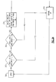
FIG. 3 , there is depicted in a process schematic block diagram illustrating an exemplary embodiment of a method of the disclosure. Atblock 300, thecontroller 30 initiates the process by determining atstep 302 both the operating fuel rack position (Rack) as a percent of the maximum fuel rack position at 100% fuel flow to theengine 32 and the operating engine speed as a percent of the maximum engine speed (RPM droop). Both determinations are made based on real time engine operating data obtained from theelectronic engine controller 34. As explained earlier, both determinations may be running averages over a selected time interval, such as , for example, the average over a 30 second running period of individual readings made at one second intervals during that period. Atblock 302, a determination is made as to whether the operating fuel rack position (Rack) is less than 85% and whether the operating engine speed (RPM) is at least 98% of the target engine operating speed (RPM droop). If yes to both conditions, i.e. the operating fuel rack position (Rack) is less than 85% and the operating engine speed is equal to or greater than 98% of the target engine operating speed (RPM droop), thecontroller 30 maintains normal operation (block 318) of thetransport refrigeration system 12. - However, if either one or both of the conditions at
block 302 is no, then thesystem controller 30, atblock 304, determines whether the operating fuel rack position (Rack) is at or greater than 90% and whether the operating engine speed is less than 98% of the target engine operating speed (RPM droop). If no to both conditions, i.e. the operating fuel rack position (Rack) is less than 90% and the operating engine speed is at least 98% of the target engine operating speed (RPM droop), thecontroller 30 maintains normal operation (block 318) of thetransport refrigeration system 12. - If, at
block 304, thecontroller 30 determines that the operating fuel rack position (RACK) is at or greater than 90% and the operating engine speed is less than 98% of the target engine operating speed (RPM droop), thesystem controller 30, atblock 306, will reduce the cooling output capacity of therefrigeration unit 12, for example by initiating an unload of thecompressor 14 or closing the suction modulation valve (SMV) 22, to bring the operating fuel rack position (Rack) to less than 85% and the operating engine speed to at least 98% of the target engine operating speed (RPM droop). Next, atblock 308, thesystem controller 30 checks to determine whether a system change request is active. A system change request could be, for example, for purposes of illustration but not limitation, a change in engine speed, a compressor unload, or transient condition. If a change request is not active atblock 308, thesystem controller 30 proceeds directly to block 312, and restricts the maximum rate of opening of the suction modulation valve (SMV) 22.to 0.1 percent per second, thereby limiting the rate of increase in refrigerant vapor flow to the suction inlet of thecompressor 14, which in turn limits a change in capacity output of thetransport refrigeration unit 12. Atblock 314, thesystem controller 30 now implements as its control limit logic maintaining the operating fuel rack position (Rack) to less than 90% and the operating engine speed at at least 98% of the target engine operating speed (RPM droop). Thesystem controller 30 will continue to monitor, block 316, the operating fuel rack position (RACK) and the operating engine speed, and permit normal operation (block 318) of the refrigeration system, including therefrigeration unit 12, so long as both the operating fuel rack position (Rack) remains less than 90% and the operating engine speed is at least 98% of the target engine operating speed (RPM droop). - However, if a system change request is active at
block 308, thesystem controller 30, atblock 310, will reduce the cooling output capacity of therefrigeration unit 12, for example by initiating an unload of thecompressor 14 or closing the suction modulation valve (SMV) 22, to bring the operating fuel rack position (Rack) to less than 70% and the operating engine speed to at least 98% of the target engine operating speed (RPM droop). Thesystem controller 30 then proceeds to block 312 and restricts the maximum rate of opening of the suction modulation valve (SMV) 22.to 0.1 percent per second, thereby limiting the rate of increase in refrigerant vapor flow to the suction inlet of thecompressor 14, which in turn limits a change in capacity output of thetransport refrigeration unit 12. Atblock 314, thesystem controller 30 now implements as its control limit logic maintaining the operating fuel rack position (Rack) to less than 90% and the operating engine speed at at least 98% of the target engine operating speed (RPM droop). During the period of operation of the refrigerant unit at reduced cooling capacity and with restriction on the rate of opening of the suction modulation valve (SMV) 22, thesystem controller 30 will allow the requested system change occur with little or no risk of an engine overload or engine stall occurring that would lead to insufficient shaft horsepower output from theengine 30. Thus, the risk of a shutdown of therefrigerant system 14 occurring as a result of the system change being implemented is greatly reduced, if not eliminated. - Additionally, at
block 316, thesystem controller 30 continues to monitor whether the operating fuel rack position (Rack) is less than 90% and whether the operating engine speed (RPM) is at least 98% of the target engine operating speed (RPM droop). If, atblock 316, thesystem controller 30 determines that the operating engine speed drops below 98% of the target operating engine speed (RPM droop) or the operating fuel rack position rises above 90%, a system alarm is activated, atblock 320, to warn of a potential impending engine stall or engine overload. - The terminology used herein is for the purpose of description, not limitation. Specific structural and functional details disclosed herein are not to be interpreted as limiting, but merely as basis for teaching one skilled in the art to employ the present invention. Those skilled in the art will also recognize the equivalents that may be substituted for elements described with reference to the exemplary embodiments disclosed herein without departing from the scope of the present invention.
- While the present invention has been particularly shown and described with reference to the exemplary embodiments as illustrated in the drawing, it will be recognized by those skilled in the art that various modifications may be made without departing from the scope of the invention. For example, in other embodiments, a different indicator of operating engine load, other than fuel rack position, could be used to monitor the operating engine load, in combination with operating engine speed in carrying out the concept of the method disclosed herein.
- Therefore, it is intended that the present disclosure not be limited to the particular embodiment(s) disclosed as, but that the disclosure will include all embodiments falling within the scope of the appended claims.
Claims (7)
- A method for controlling the power consumption of a transport refrigeration unit (10) having a refrigerant mass flow circulating within a refrigerant circuit having a refrigerant compressor (14) and having a diesel engine (32) for powering the transport refrigeration unit (10), the method comprising the step of selectively limiting refrigerant mass flow through the refrigerant circuit in response to the operating engine load on the diesel engine (32) and the operating speed of the diesel engine (32);
further comprising the steps of:monitoring the operating engine load of the diesel engine (32);monitoring the operating engine speed of the diesel engine (32); andselectively adjusting the refrigerant mass flow through the refrigerant circuit of the transport refrigeration unit (10) to maintain the operating engine load less than 98% of the maximum operating engine load and to simultaneously maintain the operating engine speed at a speed of at least 98% of a target engine operating speed. - The method as recited in claim 1 further comprising the steps of:determining whether the monitored operating engine load is less than 90% of a maximum engine load;determining whether the monitored engine speed is at a speed of at least 98% of a maximum engine speed; andif both the monitored engine operating load is at a position of at least 90% of a maximum operating engine load and the monitored engine speed is at a speed of at least 98% of a target engine operating speed, restricting an increase in refrigerant mass flow through the compressor (14).
- The method as recited in claim 2 wherein the refrigerant circuit of the transport refrigeration unit (10) includes a suction modulation valve (22) and the step restricting an increase in refrigerant mass flow through the refrigerant circuit comprises reducing a maximum rate open of the suction modulation valve to 0.1 percent per second.
- The method of claim 1 wherein the step of selectively limiting refrigerant mass flow through the refrigerant circuit in response to the operating engine load of the diesel engine (32) and the operating speed of the diesel engine (32) comprises the step of limiting refrigerant mass flow through the refrigerant circuit in response to the operating fuel rack position on the diesel engine (32) and the operating speed of the diesel engine (32).
- The method of claim 4 further comprising the steps of:monitoring the operating fuel rack position for the diesel engine (32);selectively adjusting the refrigerant mass flow through the refrigerant circuit of the transport refrigeration unit (10) to maintain the operating fuel rack position at a position less than 98% of the maximum fuel rack position and to simultaneously maintain the operating engine speed at a speed of at least 98% of a maximum engine operating speed.
- The method as recited in claim 4 further comprising the steps of:monitoring the operating fuel rack position for the diesel engine (32);determining whether the monitored fuel rack position is at a position of at least 90% of a maximum fuel rack position;determining whether the monitored engine speed is at a speed of at least 98% of a maximum engine speed; andif both the monitored fuel rack position is at a position of at least 90% of a maximum fuel rack position and the monitored engine speed is at a speed of at least 98% of a target engine operating speed, restricting an increase in refrigerant mass flow through the compressor (14).
- The method as recited in claim 6 wherein the refrigerant circuit of the transport refrigeration unit (10) includes a suction modulation valve (22) and the step restricting an increase in refrigerant mass flow through the refrigerant circuit comprises reducing a maximum rate open of the suction modulation valve to 0.1 percent per second.
Applications Claiming Priority (2)
| Application Number | Priority Date | Filing Date | Title |
|---|---|---|---|
| US38717710P | 2010-09-28 | 2010-09-28 | |
| PCT/US2011/052265 WO2012047499A2 (en) | 2010-09-28 | 2011-09-20 | Operation of transport refrigeration systems to prevent engine stall and overload |
Publications (2)
| Publication Number | Publication Date |
|---|---|
| EP2621744A2 EP2621744A2 (en) | 2013-08-07 |
| EP2621744B1 true EP2621744B1 (en) | 2016-11-02 |
Family
ID=44720168
Family Applications (1)
| Application Number | Title | Priority Date | Filing Date |
|---|---|---|---|
| EP11761782.9A Active EP2621744B1 (en) | 2010-09-28 | 2011-09-20 | Operation of transport refrigeration systems to prevent engine stall and overload |
Country Status (7)
| Country | Link |
|---|---|
| US (2) | US9499027B2 (en) |
| EP (1) | EP2621744B1 (en) |
| CN (2) | CN105667256B (en) |
| AU (1) | AU2011312647A1 (en) |
| ES (1) | ES2609611T3 (en) |
| RU (1) | RU2591105C2 (en) |
| WO (1) | WO2012047499A2 (en) |
Families Citing this family (25)
| Publication number | Priority date | Publication date | Assignee | Title |
|---|---|---|---|---|
| US9908452B2 (en) * | 2012-03-09 | 2018-03-06 | Carrier Corporation | Closed loop capacity and power management scheme for multi stage transport refrigeration system |
| EP2844519B1 (en) * | 2012-04-30 | 2019-04-03 | Thermo King Corporation | Real-time engine load control for electronically controlled engines |
| US9464827B2 (en) | 2012-04-30 | 2016-10-11 | Thermo King Corporation | Transport refrigeration system controller to engine control unit interface |
| WO2014106068A1 (en) * | 2012-12-27 | 2014-07-03 | Thermo King Corporation | Systems and methods for engine power control for transport refrigeration system |
| WO2014106232A1 (en) * | 2012-12-31 | 2014-07-03 | Thermo King Corporation | Communication protocol for transport refrigeration system |
| EP2799264A1 (en) * | 2013-04-29 | 2014-11-05 | Schmitz Cargobull AG | Utility vehicle for the transport of temperature-managed goods and method for operating a refrigerating machine intended for use in such a commercial vehicle |
| ES2928455T3 (en) * | 2013-12-26 | 2022-11-18 | Thermo King Corp | Method and system for dynamic power allocation in a transport refrigeration system |
| WO2015100398A1 (en) | 2013-12-26 | 2015-07-02 | Thermo King Corporation | Method and system for dynamic power allocation in a transport refrigeration system |
| US10723201B2 (en) | 2015-08-31 | 2020-07-28 | Thermo King Corporation | Methods and systems to control engine loading on a transport refrigeration system |
| EP3414499B1 (en) | 2016-02-10 | 2021-07-07 | Carrier Corporation | Power management for co2 transportation refrigeration system |
| US20190078839A1 (en) * | 2016-03-10 | 2019-03-14 | Carrier Corporation | Transport refrigeration unit and method of operating |
| TWI637868B (en) * | 2016-05-24 | 2018-10-11 | 財團法人工業技術研究院 | Pre-cooling system and method for logistics vehicles |
| EP3485209B1 (en) * | 2016-07-14 | 2021-12-08 | Carrier Corporation | Transport refrigeration system and method of operation |
| US10570809B2 (en) * | 2016-09-27 | 2020-02-25 | Ford Global Technologies, Llc | Methods and systems for coolant system |
| WO2018138540A1 (en) | 2017-01-27 | 2018-08-02 | Carrier Corporation | Apparatus and method for thermal event detection in a transport refrigeration unit |
| US11303107B2 (en) | 2017-02-28 | 2022-04-12 | Carrier Corporation | Apparatus and method for detecting current overload and leakage in a transport refrigeration unit |
| CN108688439A (en) | 2017-04-07 | 2018-10-23 | 开利公司 | Power management method and system for transport refrigeration unit |
| CN109210810A (en) * | 2017-07-04 | 2019-01-15 | 开利公司 | Refrigeration system and starting control method for refrigeration system |
| US11097600B2 (en) * | 2017-08-25 | 2021-08-24 | Thermo King Corporation | Method and system for adaptive power engine control |
| US10596878B2 (en) * | 2018-03-30 | 2020-03-24 | Thermo King Corporation | Systems and methods for management of eTRU |
| US10723202B2 (en) | 2018-03-30 | 2020-07-28 | Thermo King Corporation | Systems and methods for coordinated control of multiple transport refrigeration systems |
| CN109268156A (en) * | 2018-09-27 | 2019-01-25 | 潍柴动力股份有限公司 | Engine anti-extinguishing control method and control device |
| EP3771814B1 (en) * | 2019-07-29 | 2023-10-04 | Thermo King LLC | Control system and method for an electronically governed engine of a refrigeration system |
| CN113027740B (en) * | 2021-04-23 | 2023-03-28 | 阿特拉斯·科普柯(无锡)压缩机有限公司 | Control method and device for compressor system and compressor system |
| EP4082811A1 (en) * | 2021-04-30 | 2022-11-02 | Thermo King Corporation | Prime mover load control on multi-speed generator set |
Citations (2)
| Publication number | Priority date | Publication date | Assignee | Title |
|---|---|---|---|---|
| US20030226368A1 (en) * | 2002-06-05 | 2003-12-11 | Michiyasu Nosaka | Compressor device and control method for the same |
| EP1375216A1 (en) * | 2002-06-27 | 2004-01-02 | Calsonic Kansei Corporation | Vehicle control system |
Family Cites Families (102)
| Publication number | Priority date | Publication date | Assignee | Title |
|---|---|---|---|---|
| US3686891A (en) * | 1970-09-21 | 1972-08-29 | Borg Warner | Electronic safety control system for vehicle compressors |
| US3665725A (en) | 1971-01-18 | 1972-05-30 | Thermo King Corp | Capacity control for compression expansion refrigeration systems |
| US3950700A (en) * | 1971-06-29 | 1976-04-13 | Weisbart Emanuel S | Vehicle performance control system |
| US3976458A (en) * | 1973-09-12 | 1976-08-24 | George C. Jeffreys | Refrigeration means |
| GB1493966A (en) | 1974-02-11 | 1977-12-07 | Thermo King Corp | Dual drive power plant |
| US4060400A (en) | 1975-08-22 | 1977-11-29 | Henry L. Franke | Refrigerated semitrailer truck for long and local deliveries |
| US4234926A (en) | 1978-12-05 | 1980-11-18 | Sealand Service Inc. | System & method for monitoring & diagnosing faults in environmentally controlled containers, such system and method being especially adapted for remote computer controlled monitoring of numerous transportable containers over existing on-site power wiring |
| US4327558A (en) | 1980-09-17 | 1982-05-04 | Thermo King Corporation | Unloadable transport refrigeration unit control |
| US4353221A (en) | 1981-01-21 | 1982-10-12 | Thermo King Corporation | Transport refrigeration system |
| CH644478A5 (en) * | 1981-12-18 | 1984-07-31 | Cerac Inst Sa | METHOD AND MEANS FOR SUPPLYING ELECTRICAL ENERGY TO A PORTABLE TOOL. |
| US4419866A (en) | 1982-06-09 | 1983-12-13 | Thermo King Corporation | Transport refrigeration system control |
| US4663725A (en) | 1985-02-15 | 1987-05-05 | Thermo King Corporation | Microprocessor based control system and method providing better performance and better operation of a shipping container refrigeration system |
| US4667480A (en) | 1986-09-22 | 1987-05-26 | General Electric Company | Method and apparatus for controlling an electrically driven automotive air conditioner |
| US4685306A (en) | 1986-10-06 | 1987-08-11 | Westinghouse Electric Corp. | Compartmentalized transport refrigeration system |
| JPS63103727A (en) * | 1986-10-21 | 1988-05-09 | Diesel Kiki Co Ltd | Air conditioner for vehicle |
| JP2524723B2 (en) * | 1986-12-26 | 1996-08-14 | 富士重工業株式会社 | Compressor control device for vehicle cooling system |
| US4748818A (en) | 1987-06-15 | 1988-06-07 | Thermo King Corporation | Transport refrigeration system having means for enhancing the capacity of a heating cycle |
| US4790143A (en) | 1987-10-23 | 1988-12-13 | Thermo King Corporation | Method and apparatus for monitoring a transport refrigeration system and its conditioned load |
| US4789025A (en) | 1987-11-25 | 1988-12-06 | Carrier Corporation | Control apparatus for refrigerated cargo container |
| US4899550A (en) | 1988-07-18 | 1990-02-13 | Carrier Corporation | Refrigeration unit and hydraulic power system |
| US4878465A (en) | 1988-08-26 | 1989-11-07 | Thermo King Corporation | Control for automatically starting a diesel engine |
| US4899549A (en) | 1989-01-31 | 1990-02-13 | Thermo King Corporation | Transport refrigeration system with improved temperature and humidity control |
| US4949550A (en) | 1989-10-04 | 1990-08-21 | Thermo King Corporation | Method and apparatus for monitoring a transport refrigeration system and its conditioned load |
| US4932219A (en) | 1989-10-26 | 1990-06-12 | Thermo King Corporation | Transport refrigeration system with selective receiver tank pressurization |
| US4977752A (en) | 1989-12-28 | 1990-12-18 | Thermo King Corporation | Transport refrigeration including methods and apparatus for optmizing same |
| US4977751A (en) | 1989-12-28 | 1990-12-18 | Thermo King Corporation | Refrigeration system having a modulation valve which also performs function of compressor throttling valve |
| US5010740A (en) | 1990-02-07 | 1991-04-30 | Carrier Corporation | Refrigeration system with mass flow limiting device |
| US5107686A (en) | 1991-01-28 | 1992-04-28 | Thermo King Corporation | Compartmentalized transport refrigeration system |
| US5123263A (en) | 1991-07-05 | 1992-06-23 | Thermo King Corporation | Refrigeration system |
| US5193353A (en) | 1991-07-05 | 1993-03-16 | Carrier Corporation | High capacity hot gas heating system for transport refrigeration system |
| US5201185A (en) | 1991-07-11 | 1993-04-13 | Thermo King Corporation | Method of operating a transport refrigeration unit |
| US5140826A (en) | 1991-07-11 | 1992-08-25 | Thermo King Corporation | Method of operating a transport refrigeration unit |
| US5123253A (en) | 1991-07-11 | 1992-06-23 | Thermo King Corporation | Method of operating a transport refrigeration unit |
| US5222368A (en) | 1991-07-11 | 1993-06-29 | Thermo King Corporation | Method of operating a transport refigeration unit |
| US5140825A (en) | 1991-07-11 | 1992-08-25 | Thermo King Corporation | Method of operating a transport refrigeration unit |
| US5201186A (en) | 1991-07-11 | 1993-04-13 | Thermo King Corporation | Method of operating a transport refrigeration unit |
| US5161383A (en) | 1991-07-11 | 1992-11-10 | Thermo King Corporation | Method of operating a transport refrigeration unit |
| US5103783A (en) | 1991-07-11 | 1992-04-14 | Thermo King Corporation | Detection of engine fuel problems |
| US5161384A (en) | 1992-02-10 | 1992-11-10 | Thermo King Corporation | Method of operating a transport refrigeration system |
| US5168713A (en) | 1992-03-12 | 1992-12-08 | Thermo King Corporation | Method of operating a compartmentalized transport refrigeration system |
| US5172560A (en) | 1992-03-27 | 1992-12-22 | Thermo King Corporation | Method of operating a transport refrigeration system |
| US5275011A (en) | 1992-12-16 | 1994-01-04 | Thermo King Corporation | Method of operating a refrigeration system |
| US5249429A (en) | 1993-02-08 | 1993-10-05 | Thermo King Corporation | Methods of operating a refrigeration system |
| US5303560A (en) | 1993-04-15 | 1994-04-19 | Thermo King Corporation | Method and apparatus for monitoring and controlling the operation of a refrigeration unit |
| US5456088A (en) | 1993-11-12 | 1995-10-10 | Thermo King Corporation | Refrigeration unit and method of operating same |
| US5454229A (en) | 1994-05-18 | 1995-10-03 | Thermo King Corporation | Refrigeration unit control with shutdown evaluation and automatic restart |
| US6059016A (en) | 1994-08-11 | 2000-05-09 | Store Heat And Produce Energy, Inc. | Thermal energy storage and delivery system |
| US5531070A (en) * | 1994-11-25 | 1996-07-02 | New Holland North America, Inc. | Diesel engine reverse start inhibit |
| US5626027A (en) | 1994-12-21 | 1997-05-06 | Carrier Corporation | Capacity control for multi-stage compressors |
| US5557938A (en) | 1995-02-27 | 1996-09-24 | Thermo King Corporation | Transport refrigeration unit and method of operating same |
| US5579648A (en) | 1995-04-19 | 1996-12-03 | Thermo King Corporation | Method of monitoring a transport refrigeration unit and an associated conditioned load |
| US6112535A (en) | 1995-04-25 | 2000-09-05 | General Electric Company | Compressor including a motor and motor control in the compressor housing and method of manufacture |
| US5572879A (en) | 1995-05-25 | 1996-11-12 | Thermo King Corporation | Methods of operating a refrigeration unit in predetermined high and low ambient temperatures |
| DE19642832C1 (en) * | 1996-10-17 | 1997-09-18 | Daimler Benz Ag | Air-conditioning compressor control method for vehicle |
| US5907957A (en) | 1997-12-23 | 1999-06-01 | Carrier Corporation | Discharge pressure control system for transport refrigeration unit using suction modulation |
| DE29816787U1 (en) | 1998-09-18 | 2000-01-27 | WAECO-Wähning & Co GmbH, 48282 Emsdetten | Evaporative cooling arrangement for fresh service vehicles with combined driving and parking cooling |
| US6170277B1 (en) | 1999-01-19 | 2001-01-09 | Carrier Corporation | Control algorithm for maintenance of discharge pressure |
| US6148627A (en) | 1999-03-26 | 2000-11-21 | Carrier Corp | High engine coolant temperature control |
| US6148628A (en) | 1999-03-26 | 2000-11-21 | Carrier Corporation | Electronic expansion valve without pressure sensor reading |
| US6141981A (en) | 1999-03-26 | 2000-11-07 | Carrier Corporation | Superheat control for optimum capacity under power limitation and using a suction modulation valve |
| US6196012B1 (en) | 1999-03-26 | 2001-03-06 | Carrier Corporation | Generator power management |
| US6044651A (en) | 1999-03-26 | 2000-04-04 | Carrier Corporation | Economy mode for transport refrigeration units |
| EP1046525A3 (en) * | 1999-04-21 | 2002-06-12 | Carrier Corporation | Transport refrigeration unit with synchronous generator power system |
| US6223546B1 (en) * | 1999-04-21 | 2001-05-01 | Robert A. Chopko | Electrically powered transport refrigeration unit |
| DK1226394T3 (en) * | 1999-11-03 | 2008-01-14 | Synchro Data Ltd | Cooling container control system |
| US6318100B1 (en) | 2000-04-14 | 2001-11-20 | Carrier Corporation | Integrated electronic refrigerant management system |
| US6321549B1 (en) | 2000-04-14 | 2001-11-27 | Carrier Corporation | Electronic expansion valve control system |
| US6543428B1 (en) * | 2000-06-14 | 2003-04-08 | Caterpillar Inc. | Intake air separation system for an internal combustion engine |
| JP3719384B2 (en) * | 2000-11-08 | 2005-11-24 | 株式会社デンソー | Vapor compression refrigeration cycle for vehicles |
| WO2002047929A1 (en) * | 2000-12-14 | 2002-06-20 | Luk Fahrzeug-Hydraulik Gmbh & Co. Kg | Motor vehicle with an air conditioning system |
| DE10106243A1 (en) * | 2001-01-31 | 2002-08-01 | Behr Gmbh & Co | Regulating compressor of refrigerant circuit of air conditioning system of motor vehicle with which instantaneous torque is determined and compared with specified max. limiting torque and compressor is controlled depending on comparison |
| US20020108388A1 (en) * | 2001-02-15 | 2002-08-15 | Carrier Corporation | Non-synchronous generator design for electrically powered trailer refrigeration unit |
| US6367269B1 (en) | 2001-04-19 | 2002-04-09 | Thermo King Corporation | Electronic throttling valve diagnosis and preventative shutdown control |
| US6981544B2 (en) * | 2001-04-27 | 2006-01-03 | Denso Corporation | Air-conditioning apparatus including motor-driven compressor for idle stopping vehicles |
| US6487869B1 (en) | 2001-11-06 | 2002-12-03 | Themo King Corporation | Compressor capacity control system |
| JP4271459B2 (en) * | 2002-05-15 | 2009-06-03 | サンデン株式会社 | Air conditioner |
| CN1513691A (en) * | 2002-12-20 | 2004-07-21 | 株式会社日立制作所 | Hybrid motor vehicle, driving device thereof, hybrid four-wheel drive vehicle and control device thereof |
| US7043927B2 (en) | 2003-04-03 | 2006-05-16 | Carrier Corporation | Transport Refrigeration system |
| JP4355511B2 (en) * | 2003-04-10 | 2009-11-04 | カルソニックカンセイ株式会社 | Air conditioner for vehicles |
| US6708507B1 (en) | 2003-06-17 | 2004-03-23 | Thermo King Corporation | Temperature control apparatus and method of determining malfunction |
| US7143594B2 (en) | 2004-08-26 | 2006-12-05 | Thermo King Corporation | Control method for operating a refrigeration system |
| EP1647428B1 (en) * | 2004-10-14 | 2008-06-18 | Ford Global Technologies, LLC | Method for the estimation of the power consumed by the compressor of a refrigerant circuit in a motor vehicle |
| WO2007064320A1 (en) * | 2005-11-30 | 2007-06-07 | Carrier Corporation | Multi-circuit refrigerant system utilizing pulse width modulation techniques |
| CN101331369B (en) * | 2006-01-18 | 2010-06-23 | 开利公司 | Power Management System for Integrated Transport Refrigeration Units |
| CN101360959B (en) | 2006-01-20 | 2011-06-15 | 开利公司 | Method for controlling temperature in compartments of refrigerated transport unit |
| RU2386555C1 (en) * | 2006-02-24 | 2010-04-20 | Кэрриэ Копэрейшн | Vehicle and method to supress vibration therein |
| EP1996877B1 (en) | 2006-03-10 | 2014-08-27 | Carrier Corporation | Refrigerant system with control to address flooded compressor operation |
| EP1857363A1 (en) * | 2006-05-19 | 2007-11-21 | Lebrun Nimy | Temperature regulating device |
| US20090314018A1 (en) * | 2006-06-15 | 2009-12-24 | Carrier Corporation | Compressor power control |
| CN101563572B (en) | 2006-12-21 | 2012-07-11 | 开利公司 | Refrigeration system with suction regulator valve including adjustable opening and method of operation thereof |
| CN101611273B (en) | 2007-01-31 | 2011-11-16 | 开利公司 | Integral Multiple Power Conversion System for Transport Refrigeration Units |
| US20100107661A1 (en) | 2007-02-02 | 2010-05-06 | Awwad Nader S | Method for operating transport refrigeration unit with remote evaporator |
| CN101605668B (en) | 2007-02-13 | 2011-11-16 | 开利公司 | Combination operation and control of suction regulating valve and pulse width regulating valve |
| US20100236264A1 (en) | 2007-05-15 | 2010-09-23 | Carrier Corporation | Compressor motor control |
| BRPI0721710A2 (en) | 2007-06-07 | 2013-01-22 | Carrier Corp | Method and system for electric power supply for auxiliary electric loads |
| US7997092B2 (en) | 2007-09-26 | 2011-08-16 | Carrier Corporation | Refrigerant vapor compression system operating at or near zero load |
| JP2009168340A (en) * | 2008-01-16 | 2009-07-30 | Calsonic Kansei Corp | Air conditioner and its control method |
| CN201155889Y (en) * | 2008-01-30 | 2008-11-26 | 浙江吉利控股集团有限公司 | Vehicle Independent Air Conditioning System |
| US20090299534A1 (en) | 2008-05-30 | 2009-12-03 | Thermo King Corporation | Start/stop temperature control operation |
| US8776928B2 (en) | 2008-12-24 | 2014-07-15 | ENGEN Technologies | Regenerative electric drive refrigerated unit |
| US8935933B1 (en) * | 2011-07-14 | 2015-01-20 | Ronald Koelsch | Battery operated transfer refrigeration unit |
| US9221451B2 (en) * | 2012-05-17 | 2015-12-29 | Toyota Motor Engineering & Manufacturing North America, Inc. | Systems and methods for increasing fuel efficiency |
-
2011
- 2011-09-20 ES ES11761782.9T patent/ES2609611T3/en active Active
- 2011-09-20 EP EP11761782.9A patent/EP2621744B1/en active Active
- 2011-09-20 US US13/876,270 patent/US9499027B2/en active Active
- 2011-09-20 CN CN201610092317.1A patent/CN105667256B/en active Active
- 2011-09-20 CN CN201180048868.3A patent/CN103167964B/en active Active
- 2011-09-20 RU RU2013114425/11A patent/RU2591105C2/en active
- 2011-09-20 WO PCT/US2011/052265 patent/WO2012047499A2/en not_active Ceased
- 2011-09-20 AU AU2011312647A patent/AU2011312647A1/en not_active Abandoned
-
2016
- 2016-11-09 US US15/347,001 patent/US10328770B2/en active Active
Patent Citations (2)
| Publication number | Priority date | Publication date | Assignee | Title |
|---|---|---|---|---|
| US20030226368A1 (en) * | 2002-06-05 | 2003-12-11 | Michiyasu Nosaka | Compressor device and control method for the same |
| EP1375216A1 (en) * | 2002-06-27 | 2004-01-02 | Calsonic Kansei Corporation | Vehicle control system |
Also Published As
| Publication number | Publication date |
|---|---|
| RU2591105C2 (en) | 2016-07-10 |
| CN105667256B (en) | 2018-06-22 |
| WO2012047499A2 (en) | 2012-04-12 |
| US20140144164A1 (en) | 2014-05-29 |
| CN105667256A (en) | 2016-06-15 |
| AU2011312647A1 (en) | 2013-04-11 |
| US9499027B2 (en) | 2016-11-22 |
| WO2012047499A3 (en) | 2012-08-16 |
| US20170050494A1 (en) | 2017-02-23 |
| EP2621744A2 (en) | 2013-08-07 |
| ES2609611T3 (en) | 2017-04-21 |
| CN103167964A (en) | 2013-06-19 |
| CN103167964B (en) | 2016-03-23 |
| US10328770B2 (en) | 2019-06-25 |
| RU2013114425A (en) | 2014-11-10 |
Similar Documents
| Publication | Publication Date | Title |
|---|---|---|
| US10328770B2 (en) | Operation of transport refrigeration systems to prevent engine stall and overload | |
| EP2822791B1 (en) | Method and system for adjusting engine speed in a transport refrigeration system | |
| EP2118590B1 (en) | Method for operating transport refrigeration unit with remote evaporator | |
| US6318100B1 (en) | Integrated electronic refrigerant management system | |
| EP2588819B1 (en) | Evaporator refrigerant saturation demand defrost | |
| US9573440B2 (en) | Engine throttle position sensor calibration | |
| US9908452B2 (en) | Closed loop capacity and power management scheme for multi stage transport refrigeration system | |
| WO2017007877A1 (en) | Multi-compartment transport refrigeration system with economizer | |
| US6148627A (en) | High engine coolant temperature control | |
| EP3771814A1 (en) | Control system and method for an electronically governed engine of a refrigeration system | |
| EP1039253B1 (en) | Superheat control for optimum capacity under power limitation and using a suction modulation valve | |
| EP3371527B1 (en) | Transport refrigeration system and method of operating | |
| US12065018B2 (en) | Transport refrigeration systems | |
| US10823484B2 (en) | Intelligent voltage control for electric heat and defrost in transport refrigeration system | |
| EP3320277B1 (en) | Multi-compartment transport refrigeration system with economizer | |
| US11338648B2 (en) | Engine for a transport refrigeration unit with air management valve | |
| HK1164989B (en) | Truck trailer refrigeration system |
Legal Events
| Date | Code | Title | Description |
|---|---|---|---|
| PUAI | Public reference made under article 153(3) epc to a published international application that has entered the european phase |
Free format text: ORIGINAL CODE: 0009012 |
|
| 17P | Request for examination filed |
Effective date: 20130424 |
|
| AK | Designated contracting states |
Kind code of ref document: A2 Designated state(s): AL AT BE BG CH CY CZ DE DK EE ES FI FR GB GR HR HU IE IS IT LI LT LU LV MC MK MT NL NO PL PT RO RS SE SI SK SM TR |
|
| DAX | Request for extension of the european patent (deleted) | ||
| PUAG | Search results despatched under rule 164(2) epc together with communication from examining division |
Free format text: ORIGINAL CODE: 0009017 |
|
| 17Q | First examination report despatched |
Effective date: 20150831 |
|
| B565 | Issuance of search results under rule 164(2) epc |
Effective date: 20150831 |
|
| GRAP | Despatch of communication of intention to grant a patent |
Free format text: ORIGINAL CODE: EPIDOSNIGR1 |
|
| INTG | Intention to grant announced |
Effective date: 20160506 |
|
| GRAS | Grant fee paid |
Free format text: ORIGINAL CODE: EPIDOSNIGR3 |
|
| GRAA | (expected) grant |
Free format text: ORIGINAL CODE: 0009210 |
|
| AK | Designated contracting states |
Kind code of ref document: B1 Designated state(s): AL AT BE BG CH CY CZ DE DK EE ES FI FR GB GR HR HU IE IS IT LI LT LU LV MC MK MT NL NO PL PT RO RS SE SI SK SM TR |
|
| REG | Reference to a national code |
Ref country code: GB Ref legal event code: FG4D |
|
| REG | Reference to a national code |
Ref country code: AT Ref legal event code: REF Ref document number: 841450 Country of ref document: AT Kind code of ref document: T Effective date: 20161115 Ref country code: CH Ref legal event code: EP |
|
| REG | Reference to a national code |
Ref country code: IE Ref legal event code: FG4D |
|
| REG | Reference to a national code |
Ref country code: DE Ref legal event code: R096 Ref document number: 602011031963 Country of ref document: DE |
|
| PG25 | Lapsed in a contracting state [announced via postgrant information from national office to epo] |
Ref country code: LV Free format text: LAPSE BECAUSE OF FAILURE TO SUBMIT A TRANSLATION OF THE DESCRIPTION OR TO PAY THE FEE WITHIN THE PRESCRIBED TIME-LIMIT Effective date: 20161102 |
|
| REG | Reference to a national code |
Ref country code: NL Ref legal event code: MP Effective date: 20161102 |
|
| REG | Reference to a national code |
Ref country code: LT Ref legal event code: MG4D |
|
| REG | Reference to a national code |
Ref country code: AT Ref legal event code: MK05 Ref document number: 841450 Country of ref document: AT Kind code of ref document: T Effective date: 20161102 |
|
| REG | Reference to a national code |
Ref country code: ES Ref legal event code: FG2A Ref document number: 2609611 Country of ref document: ES Kind code of ref document: T3 Effective date: 20170421 |
|
| PG25 | Lapsed in a contracting state [announced via postgrant information from national office to epo] |
Ref country code: NO Free format text: LAPSE BECAUSE OF FAILURE TO SUBMIT A TRANSLATION OF THE DESCRIPTION OR TO PAY THE FEE WITHIN THE PRESCRIBED TIME-LIMIT Effective date: 20170202 Ref country code: GR Free format text: LAPSE BECAUSE OF FAILURE TO SUBMIT A TRANSLATION OF THE DESCRIPTION OR TO PAY THE FEE WITHIN THE PRESCRIBED TIME-LIMIT Effective date: 20170203 Ref country code: SE Free format text: LAPSE BECAUSE OF FAILURE TO SUBMIT A TRANSLATION OF THE DESCRIPTION OR TO PAY THE FEE WITHIN THE PRESCRIBED TIME-LIMIT Effective date: 20161102 Ref country code: LT Free format text: LAPSE BECAUSE OF FAILURE TO SUBMIT A TRANSLATION OF THE DESCRIPTION OR TO PAY THE FEE WITHIN THE PRESCRIBED TIME-LIMIT Effective date: 20161102 Ref country code: NL Free format text: LAPSE BECAUSE OF FAILURE TO SUBMIT A TRANSLATION OF THE DESCRIPTION OR TO PAY THE FEE WITHIN THE PRESCRIBED TIME-LIMIT Effective date: 20161102 |
|
| PG25 | Lapsed in a contracting state [announced via postgrant information from national office to epo] |
Ref country code: PT Free format text: LAPSE BECAUSE OF FAILURE TO SUBMIT A TRANSLATION OF THE DESCRIPTION OR TO PAY THE FEE WITHIN THE PRESCRIBED TIME-LIMIT Effective date: 20170302 Ref country code: FI Free format text: LAPSE BECAUSE OF FAILURE TO SUBMIT A TRANSLATION OF THE DESCRIPTION OR TO PAY THE FEE WITHIN THE PRESCRIBED TIME-LIMIT Effective date: 20161102 Ref country code: RS Free format text: LAPSE BECAUSE OF FAILURE TO SUBMIT A TRANSLATION OF THE DESCRIPTION OR TO PAY THE FEE WITHIN THE PRESCRIBED TIME-LIMIT Effective date: 20161102 Ref country code: AT Free format text: LAPSE BECAUSE OF FAILURE TO SUBMIT A TRANSLATION OF THE DESCRIPTION OR TO PAY THE FEE WITHIN THE PRESCRIBED TIME-LIMIT Effective date: 20161102 Ref country code: PL Free format text: LAPSE BECAUSE OF FAILURE TO SUBMIT A TRANSLATION OF THE DESCRIPTION OR TO PAY THE FEE WITHIN THE PRESCRIBED TIME-LIMIT Effective date: 20161102 Ref country code: IS Free format text: LAPSE BECAUSE OF FAILURE TO SUBMIT A TRANSLATION OF THE DESCRIPTION OR TO PAY THE FEE WITHIN THE PRESCRIBED TIME-LIMIT Effective date: 20170302 Ref country code: HR Free format text: LAPSE BECAUSE OF FAILURE TO SUBMIT A TRANSLATION OF THE DESCRIPTION OR TO PAY THE FEE WITHIN THE PRESCRIBED TIME-LIMIT Effective date: 20161102 |
|
| REG | Reference to a national code |
Ref country code: DE Ref legal event code: R082 Ref document number: 602011031963 Country of ref document: DE Representative=s name: SCHMITT-NILSON SCHRAUD WAIBEL WOHLFROM PATENTA, DE |
|
| PG25 | Lapsed in a contracting state [announced via postgrant information from national office to epo] |
Ref country code: RO Free format text: LAPSE BECAUSE OF FAILURE TO SUBMIT A TRANSLATION OF THE DESCRIPTION OR TO PAY THE FEE WITHIN THE PRESCRIBED TIME-LIMIT Effective date: 20161102 Ref country code: EE Free format text: LAPSE BECAUSE OF FAILURE TO SUBMIT A TRANSLATION OF THE DESCRIPTION OR TO PAY THE FEE WITHIN THE PRESCRIBED TIME-LIMIT Effective date: 20161102 Ref country code: SK Free format text: LAPSE BECAUSE OF FAILURE TO SUBMIT A TRANSLATION OF THE DESCRIPTION OR TO PAY THE FEE WITHIN THE PRESCRIBED TIME-LIMIT Effective date: 20161102 Ref country code: CZ Free format text: LAPSE BECAUSE OF FAILURE TO SUBMIT A TRANSLATION OF THE DESCRIPTION OR TO PAY THE FEE WITHIN THE PRESCRIBED TIME-LIMIT Effective date: 20161102 Ref country code: DK Free format text: LAPSE BECAUSE OF FAILURE TO SUBMIT A TRANSLATION OF THE DESCRIPTION OR TO PAY THE FEE WITHIN THE PRESCRIBED TIME-LIMIT Effective date: 20161102 |
|
| REG | Reference to a national code |
Ref country code: DE Ref legal event code: R097 Ref document number: 602011031963 Country of ref document: DE |
|
| REG | Reference to a national code |
Ref country code: FR Ref legal event code: PLFP Year of fee payment: 7 |
|
| PG25 | Lapsed in a contracting state [announced via postgrant information from national office to epo] |
Ref country code: SM Free format text: LAPSE BECAUSE OF FAILURE TO SUBMIT A TRANSLATION OF THE DESCRIPTION OR TO PAY THE FEE WITHIN THE PRESCRIBED TIME-LIMIT Effective date: 20161102 Ref country code: BG Free format text: LAPSE BECAUSE OF FAILURE TO SUBMIT A TRANSLATION OF THE DESCRIPTION OR TO PAY THE FEE WITHIN THE PRESCRIBED TIME-LIMIT Effective date: 20170202 Ref country code: BE Free format text: LAPSE BECAUSE OF FAILURE TO SUBMIT A TRANSLATION OF THE DESCRIPTION OR TO PAY THE FEE WITHIN THE PRESCRIBED TIME-LIMIT Effective date: 20161102 |
|
| PLBE | No opposition filed within time limit |
Free format text: ORIGINAL CODE: 0009261 |
|
| STAA | Information on the status of an ep patent application or granted ep patent |
Free format text: STATUS: NO OPPOSITION FILED WITHIN TIME LIMIT |
|
| 26N | No opposition filed |
Effective date: 20170803 |
|
| PG25 | Lapsed in a contracting state [announced via postgrant information from national office to epo] |
Ref country code: SI Free format text: LAPSE BECAUSE OF FAILURE TO SUBMIT A TRANSLATION OF THE DESCRIPTION OR TO PAY THE FEE WITHIN THE PRESCRIBED TIME-LIMIT Effective date: 20161102 |
|
| REG | Reference to a national code |
Ref country code: CH Ref legal event code: PL |
|
| PG25 | Lapsed in a contracting state [announced via postgrant information from national office to epo] |
Ref country code: MC Free format text: LAPSE BECAUSE OF FAILURE TO SUBMIT A TRANSLATION OF THE DESCRIPTION OR TO PAY THE FEE WITHIN THE PRESCRIBED TIME-LIMIT Effective date: 20161102 |
|
| REG | Reference to a national code |
Ref country code: IE Ref legal event code: MM4A |
|
| PG25 | Lapsed in a contracting state [announced via postgrant information from national office to epo] |
Ref country code: LU Free format text: LAPSE BECAUSE OF NON-PAYMENT OF DUE FEES Effective date: 20170920 |
|
| PG25 | Lapsed in a contracting state [announced via postgrant information from national office to epo] |
Ref country code: IE Free format text: LAPSE BECAUSE OF NON-PAYMENT OF DUE FEES Effective date: 20170920 Ref country code: LI Free format text: LAPSE BECAUSE OF NON-PAYMENT OF DUE FEES Effective date: 20170930 Ref country code: CH Free format text: LAPSE BECAUSE OF NON-PAYMENT OF DUE FEES Effective date: 20170930 |
|
| REG | Reference to a national code |
Ref country code: FR Ref legal event code: PLFP Year of fee payment: 8 |
|
| PG25 | Lapsed in a contracting state [announced via postgrant information from national office to epo] |
Ref country code: MT Free format text: LAPSE BECAUSE OF NON-PAYMENT OF DUE FEES Effective date: 20170920 |
|
| PG25 | Lapsed in a contracting state [announced via postgrant information from national office to epo] |
Ref country code: HU Free format text: LAPSE BECAUSE OF FAILURE TO SUBMIT A TRANSLATION OF THE DESCRIPTION OR TO PAY THE FEE WITHIN THE PRESCRIBED TIME-LIMIT; INVALID AB INITIO Effective date: 20110920 |
|
| PG25 | Lapsed in a contracting state [announced via postgrant information from national office to epo] |
Ref country code: CY Free format text: LAPSE BECAUSE OF NON-PAYMENT OF DUE FEES Effective date: 20161102 |
|
| PG25 | Lapsed in a contracting state [announced via postgrant information from national office to epo] |
Ref country code: MK Free format text: LAPSE BECAUSE OF FAILURE TO SUBMIT A TRANSLATION OF THE DESCRIPTION OR TO PAY THE FEE WITHIN THE PRESCRIBED TIME-LIMIT Effective date: 20161102 |
|
| PG25 | Lapsed in a contracting state [announced via postgrant information from national office to epo] |
Ref country code: TR Free format text: LAPSE BECAUSE OF FAILURE TO SUBMIT A TRANSLATION OF THE DESCRIPTION OR TO PAY THE FEE WITHIN THE PRESCRIBED TIME-LIMIT Effective date: 20161102 |
|
| PG25 | Lapsed in a contracting state [announced via postgrant information from national office to epo] |
Ref country code: AL Free format text: LAPSE BECAUSE OF FAILURE TO SUBMIT A TRANSLATION OF THE DESCRIPTION OR TO PAY THE FEE WITHIN THE PRESCRIBED TIME-LIMIT Effective date: 20161102 |
|
| P01 | Opt-out of the competence of the unified patent court (upc) registered |
Effective date: 20230527 |
|
| PGFP | Annual fee paid to national office [announced via postgrant information from national office to epo] |
Ref country code: IT Payment date: 20240820 Year of fee payment: 14 |
|
| PGFP | Annual fee paid to national office [announced via postgrant information from national office to epo] |
Ref country code: ES Payment date: 20241001 Year of fee payment: 14 |
|
| PGFP | Annual fee paid to national office [announced via postgrant information from national office to epo] |
Ref country code: DE Payment date: 20250820 Year of fee payment: 15 |
|
| PGFP | Annual fee paid to national office [announced via postgrant information from national office to epo] |
Ref country code: GB Payment date: 20250820 Year of fee payment: 15 |
|
| PGFP | Annual fee paid to national office [announced via postgrant information from national office to epo] |
Ref country code: FR Payment date: 20250821 Year of fee payment: 15 |