EP2621691B1 - Appareil automatisé pour la construction d'ensembles d'éléments de bâtiment - Google Patents
Appareil automatisé pour la construction d'ensembles d'éléments de bâtiment Download PDFInfo
- Publication number
- EP2621691B1 EP2621691B1 EP11831261.0A EP11831261A EP2621691B1 EP 2621691 B1 EP2621691 B1 EP 2621691B1 EP 11831261 A EP11831261 A EP 11831261A EP 2621691 B1 EP2621691 B1 EP 2621691B1
- Authority
- EP
- European Patent Office
- Prior art keywords
- clamping
- structural members
- unit
- movable carriage
- wall panel
- Prior art date
- Legal status (The legal status is an assumption and is not a legal conclusion. Google has not performed a legal analysis and makes no representation as to the accuracy of the status listed.)
- Active
Links
- 238000000429 assembly Methods 0.000 title description 4
- 230000000712 assembly Effects 0.000 title 1
- 230000033001 locomotion Effects 0.000 claims description 40
- 238000000034 method Methods 0.000 claims description 39
- 238000010276 construction Methods 0.000 claims description 22
- 230000007246 mechanism Effects 0.000 claims description 10
- 230000008569 process Effects 0.000 description 15
- 230000006870 function Effects 0.000 description 7
- 230000015654 memory Effects 0.000 description 7
- 230000009471 action Effects 0.000 description 5
- 238000012545 processing Methods 0.000 description 4
- 210000000707 wrist Anatomy 0.000 description 4
- 241000256247 Spodoptera exigua Species 0.000 description 3
- 238000013461 design Methods 0.000 description 3
- 238000013519 translation Methods 0.000 description 3
- 229910000831 Steel Inorganic materials 0.000 description 2
- 238000004590 computer program Methods 0.000 description 2
- 238000010586 diagram Methods 0.000 description 2
- 238000003780 insertion Methods 0.000 description 2
- 230000037431 insertion Effects 0.000 description 2
- 230000000670 limiting effect Effects 0.000 description 2
- 238000004519 manufacturing process Methods 0.000 description 2
- 238000012986 modification Methods 0.000 description 2
- 230000004048 modification Effects 0.000 description 2
- 230000036961 partial effect Effects 0.000 description 2
- 230000002441 reversible effect Effects 0.000 description 2
- 230000003068 static effect Effects 0.000 description 2
- 239000010959 steel Substances 0.000 description 2
- 241000937378 Everettia interior Species 0.000 description 1
- 239000000853 adhesive Substances 0.000 description 1
- 230000001070 adhesive effect Effects 0.000 description 1
- 230000008901 benefit Effects 0.000 description 1
- 230000005540 biological transmission Effects 0.000 description 1
- 238000004891 communication Methods 0.000 description 1
- 238000002788 crimping Methods 0.000 description 1
- 238000013500 data storage Methods 0.000 description 1
- 230000000694 effects Effects 0.000 description 1
- 230000005484 gravity Effects 0.000 description 1
- 238000005304 joining Methods 0.000 description 1
- 238000005392 polarisation enhancment during attached nucleus testing Methods 0.000 description 1
- 238000003825 pressing Methods 0.000 description 1
- 239000002994 raw material Substances 0.000 description 1
- 230000002829 reductive effect Effects 0.000 description 1
- 230000001105 regulatory effect Effects 0.000 description 1
- 230000035939 shock Effects 0.000 description 1
- 238000003860 storage Methods 0.000 description 1
- XLYOFNOQVPJJNP-UHFFFAOYSA-N water Substances O XLYOFNOQVPJJNP-UHFFFAOYSA-N 0.000 description 1
- 238000003466 welding Methods 0.000 description 1
Images


Classifications
-
- B—PERFORMING OPERATIONS; TRANSPORTING
- B27—WORKING OR PRESERVING WOOD OR SIMILAR MATERIAL; NAILING OR STAPLING MACHINES IN GENERAL
- B27F—DOVETAILED WORK; TENONS; SLOTTING MACHINES FOR WOOD OR SIMILAR MATERIAL; NAILING OR STAPLING MACHINES
- B27F7/00—Nailing or stapling; Nailed or stapled work
- B27F7/003—Nailing or stapling machines provided with assembling means
-
- B—PERFORMING OPERATIONS; TRANSPORTING
- B25—HAND TOOLS; PORTABLE POWER-DRIVEN TOOLS; MANIPULATORS
- B25J—MANIPULATORS; CHAMBERS PROVIDED WITH MANIPULATION DEVICES
- B25J9/00—Programme-controlled manipulators
- B25J9/16—Programme controls
- B25J9/1679—Programme controls characterised by the tasks executed
- B25J9/1687—Assembly, peg and hole, palletising, straight line, weaving pattern movement
-
- B—PERFORMING OPERATIONS; TRANSPORTING
- B27—WORKING OR PRESERVING WOOD OR SIMILAR MATERIAL; NAILING OR STAPLING MACHINES IN GENERAL
- B27F—DOVETAILED WORK; TENONS; SLOTTING MACHINES FOR WOOD OR SIMILAR MATERIAL; NAILING OR STAPLING MACHINES
- B27F7/00—Nailing or stapling; Nailed or stapled work
- B27F7/006—Nailing or stapling machines provided with means for operating on discrete points
-
- E—FIXED CONSTRUCTIONS
- E04—BUILDING
- E04B—GENERAL BUILDING CONSTRUCTIONS; WALLS, e.g. PARTITIONS; ROOFS; FLOORS; CEILINGS; INSULATION OR OTHER PROTECTION OF BUILDINGS
- E04B2/00—Walls, e.g. partitions, for buildings; Wall construction with regard to insulation; Connections specially adapted to walls
- E04B2/56—Load-bearing walls of framework or pillarwork; Walls incorporating load-bearing elongated members
- E04B2/70—Load-bearing walls of framework or pillarwork; Walls incorporating load-bearing elongated members with elongated members of wood
-
- Y—GENERAL TAGGING OF NEW TECHNOLOGICAL DEVELOPMENTS; GENERAL TAGGING OF CROSS-SECTIONAL TECHNOLOGIES SPANNING OVER SEVERAL SECTIONS OF THE IPC; TECHNICAL SUBJECTS COVERED BY FORMER USPC CROSS-REFERENCE ART COLLECTIONS [XRACs] AND DIGESTS
- Y10—TECHNICAL SUBJECTS COVERED BY FORMER USPC
- Y10T—TECHNICAL SUBJECTS COVERED BY FORMER US CLASSIFICATION
- Y10T29/00—Metal working
- Y10T29/49—Method of mechanical manufacture
- Y10T29/49616—Structural member making
- Y10T29/49623—Static structure, e.g., a building component
- Y10T29/49629—Panel
-
- Y—GENERAL TAGGING OF NEW TECHNOLOGICAL DEVELOPMENTS; GENERAL TAGGING OF CROSS-SECTIONAL TECHNOLOGIES SPANNING OVER SEVERAL SECTIONS OF THE IPC; TECHNICAL SUBJECTS COVERED BY FORMER USPC CROSS-REFERENCE ART COLLECTIONS [XRACs] AND DIGESTS
- Y10—TECHNICAL SUBJECTS COVERED BY FORMER USPC
- Y10T—TECHNICAL SUBJECTS COVERED BY FORMER US CLASSIFICATION
- Y10T29/00—Metal working
- Y10T29/53—Means to assemble or disassemble
Definitions
- This invention relates generally to construction of buildings, and more particularly relates to a system for the construction of wall panels according to the preamble of claim 1 and a method of constructing a wall panel according to the preamble of claim 10.
- a system and such a method are generally known from US 4 567 821 A .
- Wall panels for the wall of a dwelling typically comprise a series of lumber boards arranged in a predetermined pattern and nailed together.
- Wall panel design varies from house to house because of consumer demand for individualized home design, although in some instances multiple wall panels for the same house will have the same arrangement.
- Most wall panels will include top and bottom horizontal boards and a number (often determined by a building code) of vertical boards to provide support. Often two or more vertical boards will be arranged in abutted fashion with the long axis of at least of one rotated 90° to form strengthened posts for corners and wall intersections.
- the horizontal and vertical boards are nailed together to form a panel.
- the panel is then installed in the dwelling at a desired time.
- the panels may be fabricated on-site or remotely for subsequent transport and use.
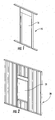
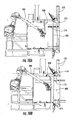
- Some wall panels include so-called “rough openings", which are openings within the frame of the panel for windows, doors and the like (see, e.g., Figures 1 and 2 , which show a wall panel 15 that includes an opening 16 for a door, and a wall panel 20 that includes a rough opening 21 for a window).
- the numbers and sizes of boards around rough openings are often regulated by building codes. Also, the locations and sizes of rough openings can vary significantly based on the personal preferences of the homeowner or builder. As a result, automation of the wall panel fabrication process has been limited.
- wall panels and in particular wall panels with rough openings, can be constructed in a more extemporaneous fashion with reduced setup and change-over time from panel-to-panel.
- the present invention provides a system for constructing wall panels comprising a plurality of structural members according to claim 1.
- the system comprises: a source of structural members of predetermined size; a horizontal table configured to support planks as they are being formed into a wall panel, the table including a stationary section and a movable carriage that is configured to move in a longitudinal direction toward and away from the stationary section; an articulated arm unit having a gripper, the articulating arm unit positioned to retrieve structural members from the source with the gripper and place them on the table; at least one first clamping unit mounted to the stationary section for clamping structural members thereto; at least one second clamping unit mounted to the movable carriage for clamping structural members thereto; and a controller that controls the movement of the articulating arm unit and the movable carriage.
- the presence of the movable carriage can enable the system to produce wall panels of almost any length.
- the present invention provides a method of constructing a wall panel comprising a plurality of structural members according to claim 10.
- the method comprises the steps of: (a) providing a horizontal table configured to support planks as they are being formed into a wall panel, the table including a stationary section and a movable carriage that is configured to move in a longitudinal direction relative to the stationary section; wherein at least one first clamping unit is mounted to the stationary section for clamping structural members thereto; and at least one second clamping unit mounted to the movable carriage for clamping structural members thereto; (b) forming a subassembly of structural members, wherein at least one structural member is clamped with the first clamping units; (c) clamping the structural member with the second clamping unit; (d) releasing the first clamping units; and (e) moving the movable carriage relative to the stationary table section to move the subassembly relative to the stationary table section.
- This method can enable the construction of wall panels of almost any length.
- embodiments of the present invention are directed to a method of placing a structural member during the construction of a wall panel comprising a plurality of structural members.
- the method comprises the steps of: providing parallel first and second structural members extending in a longitudinal direction; placing, with an automated system, a third structural member between the first and second structural members, the third structural member being oriented at an oblique angle relative to the first and second structural members; and rotating, with the automated system, the third structural member to a position that is substantially perpendicular to the first and second structural members.
- This technique can enable or facilitate the automated placement of structural members in tight places that can be created due to the inconsistency of structural member dimensions and quality.
- embodiments of the present invention are directed to a method of constructing a wall panel comprising a plurality of structural members, the method comprising the steps of: with an automated system, positioning a first structural member on a build surface; with the automated system, positioning a second structural member on the build surface, the second structural member being in contact with the first structural member but not secured to the first structural member; and with the automated system, positioning a third structural member on the build surface, the third structural member being in contact with the second structural member, thereby using the second structural member as a positioning fixture.
- This technique can allow some structural members to be "self-fixturing" for other structural members, thereby simplifying the build process.
- embodiments of the present invention are directed to a method of determining the construction sequence of a wall panel comprising a plurality of structural members, comprising the steps of: (a) programmatically determining the dimensions of each structural member based on a data file; (b) programmatically determining structural member parameters; and (c) programmatically creating a nominal build sequence from the structural member parameters.
- embodiments of the present invention are directed to a method of programmatically and via automation constructing a wall panel comprising a plurality of structural members, the method comprising the steps of: (a) selecting a structural member for inclusion in the wall panel; (b) determining nailing requirements based on the structural member's use and location; (c) retrieving the structural member from a structural member source; (d) determining whether to move an already assembled subassembly relative to a build table based on the structural member's size, orientation, and/or potential interference with another structural member or fixture; (e) moving the already assembled subassembly relative to the table if step (d) so determines; (f) positioning the structural member on the build table; (g) determining whether to attach the structural member to another structural member based on its position and/or use; (h) attaching the structural members if step (g) so determines; and (i) repeating steps (a)-(h) for additional structural members.
- embodiments of the present invention are directed to a method of constructing a wall panel comprising a plurality of structural members, comprising the steps of: (a) providing a horizontal table configured to support structural members as they are being formed into a wall panel, the table including a stationary section and a translation unit that is configured to move an already assembled subassembly relative to the stationary section; (b) forming a subassembly of structural members on the stationary section; (c) moving the subassembly relative to the stationary table section to a new position; and (d) adding additional structural members to the subassembly in its new position.
- spatially relative terms such as “under”, “below”, “lower”, “over”, “upper” and the like, may be used herein for ease of description to describe one element or feature's relationship to another element(s) or feature(s) as illustrated in the figures. It will be understood that the spatially relative terms are intended to encompass different orientations of the device in use or operation in addition to the orientation depicted in the figures. For example, if the device in the figures is turned over, elements described as “under” or “beneath” other elements or features would then be oriented “over” or “above” the other elements or features. Thus, the exemplary term “under” can encompass both an orientation of over and under. The device may be otherwise oriented (rotated 90 degrees or at other orientations) and the spatially relative descriptors used herein interpreted accordingly.
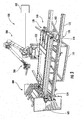
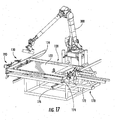
- the system 100 includes as general components a source of wall panel planks 400 (illustrated herein as a rack), an articulating arm unit 300 having a gripper/nailer 200, and a table 110. These are described in greater detail below.
- the term “longitudinal” and derivatives thereof mean the direction defined by a horizontal vector extending through the articulating arm unit 300 and the center of the table 110.
- the term “transverse” and derivatives thereof mean the horizontal direction perpendicular to the longitudinal direction (i.e., “across” the table 110 ). This direction is also synonymous with the "height” direction of a wall panel.
- the "depth” or “thickness” direction of a wall panel is synonymous with the vertical direction of the table 110.
- wall panel is intended to encompass wall panels employed in the walls of residential and commercial buildings that comprise a plurality of structural members (typically straight wooden boards or planks, although some wall panels include straight steel studs). Wooden boards are typically nailed together, but steel structural members may be attached with screws, crimping, welding, adhesives or the like.
- wall panel is also intended to encompass subassemblies for wall panels, such as rough openings for doors, windows and the like.
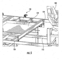
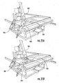
- the table 110 has two primary sections: a stationary section 120 and a movable carriage 170 that can be used as an additional build area and to pull or push (extrude, both positive and negative) wall sub-assemblies to appropriate length-wise positions for assembly.
- Each of the stationary section 120 and the movable carriage 170 incorporates clamping and positioning elements to aid in the accurate positioning and securing on the boards. Some of these clamps serve a second purpose of holding wall sub-assemblies in a fixed position relative to the particular build section.
- a skeletal frame 112 supports the stationary section 120 from below.
- the stationary section 120 has one or more horizontal table surfaces 122 (see Figure 3 )mounted on the frame 112 in the work envelope of the articulating arm unit 300, although in some embodiments additional table surfaces may be employed.
- the table surfaces 122 receive work pieces ( i.e. , planks) from the articulated arm unit 300, which places the pieces in relative positions suitable for clamping and/or nailing.
- the table surfaces 122 need not be as large as the desired wall; its characteristic length (the distance from a point closest to the articulating arm unit 300 to a point furthest from the articulating arm unit 300 ) may be determined by various factors such as expected rough opening sizes or available space or articulated arm reach.
- the wall height dimension (in plane of the surface and perpendicular to the length direction) may be adjustable at either the top or bottom or both (top and bottom here referring to wall plate or plank locations) by adding surface extensions or moving sub-sections appropriate for the desired wall height (e.g., 8', 9' or 12').
- the stationary section 120 may include fixed stops 124 to provide "zero" reference locations for boards and sub-assemblies. These stops 124 may be positioned at two or more of the table surface edges. These stops 124 can also be used to provide an opposing force when clamping a sub-assembly in the length or height directions. Alternatively, the lengthwise stops 124 may be incorporated in the "stud clamping" mechanisms described below.
- the movable carriage 170 includes cross-members 172 and rails 174 on a frame 175.
- the movable carriage 170 is mounted to the frame 112 on a pair of linear bearings 176 that allow motion along the length axis but constrain movement in the other axes as well as prevent rotation about any axis.
- Other means, such as wheels on tracks, may be used to achieve this constrained motion.
- the motion is actuated by means of a servo-motor 180 mounted on the frame 112 and coupled to the movable carriage 170 by a transmission 181 and a pinion gear 182 that acts on a toothed rack 183.
- the allowable range of motion of the movable carriage 170 may vary from short distances such as 3' or less to long distances such as 16' or more. Thus, if the range is only 3' and a 5' translation is desired, the motion can be accomplished in an "inch-worm fashion" (described below) in two strokes of 2' and 3'.
- the table 110 includes a number of different varieties of clamping mechanisms.
- Top and bottom board clamp units 130 are mounted to the frame 112 (see Figures 11A and 11B ).
- Each has a base 132 with a bearing surface 133 that faces the opposite side of the table 112.
- the top and bottom board clamp units 130 are mounted to provide a clamping force on the top and bottom planks of a wall panel being built in a direction along the height axis of the wall panel, and in doing so can capture boards (such as studs) positioned between the top and bottom planks.
- the top and bottom board clamp units 130 may be mounted to the stationary section 120 and/or frame 112 of the table 110 in such a way that they may be moved along the height axis to allow the construction of taller or shorter wall panels (see Figures 11A and 11B for different clamping positions). Adjustment for wall panel height may be achieved, for example, by including rails extending transversely from the stationary table section 120 with holes (shown at 135 in broken line in Figures 11A and 11B ). that receive pins on the base 132 of the clamping units 130.
- the clamps 130 may act as against a rigid stop or it may be paired with an opposing clamp engaged with the opposing top or bottom plank.
- the clamp units 130 also include a clamping member 134 that applies downward pressure on the upper surface of the top or bottom plank.
- the clamping member 134 is actuated between retracted and extended positions by a pneumatic cylinder 136 that acts through a linkage 138 attached to the clamping member 134 (see Figures 4A and 4B ).
- the clamping unit 130 may be raised or lowered in height relative to the stationary section 120 (to address different wall panel depths) through any number of means, including pins, rods or other projections from the base 132 that are received in or engage the frame 112.
- the stud clamping units 150 include both active and passive clamping members.
- the active clamping member 162 is pivotally attached to the frame 112 below the table surface 122 and is can be actuated between extended and retracted positions via a pneumatic cylinder 152 and a retraction linkage 154.
- the passive clamping member 164 is also pivotally attached to the frame 112 , but its motion is limited in one direction to an extended vertical disposition (its default orientation, which may be maintained by a spring or gravity counterbalance) but unlimited rotation in the opposite direction, thus allowing a fastened board to translate past the passive clamping member 164 without interference.
- the clamping position is nominally the thickness of the board to be clamped, thus holding it in an accurate position but not necessarily squeezing it tight.
- the board is held in its correct position and can be fastened permanently to another board by one of the several nail guns.
- the active clamping member 162 may be mounted on the movable carriage 170 and positioned by the movable carriage 170 to perform the clamping action at variable distances.
- the stud clamping units 150 may be repositioned by a variety of means to locations appropriate for the desired wall height. Variation in wall depth may be accommodated by modifying the depth dimension of the clamping member 162 to accommodate a depth of 4", 6", or 8".
- the movable carriage 170 includes a set of "puller" clamps 190 (acting in the depth direction) that are similar in construction to the top and bottom board clamps 130.
- the puller clamps 190 are positioned to engage at least the top and bottom boards of the wall panel.
- the puller clamps 190 can be mounted in different transverse positions on the movable carriage 170 to accommodate the construction of wall panels of different heights (see Figures 12A and 12B , which illustrate rails 180 on which the puller clamps 190 may be mounted, and posts 182 that can receive an opening in the base of the puller clamps 190).
- the puller clamps 190 have the adjustable depth feature described above for the clamping units 130 (see Figures 14A and 14B for illustration of lowered and raised mounting positions of the puller clamps 190 ).
- the top and bottom planks (along with any boards secured thereto by nails) may be moved to a new position relative to the articulated arm 300. This position may be farther from or closer to the articulated arm unit 300.
- the clamping units 130 on the stationary section 120 of table 110 (acting in the depth direction) must be released to allow free movement of the boards.
- a set of "pusher" clamping units 192 may be disposed along the movable carriage 170 to provide a "pushing" action between the movable carriage 120 and the stationary section 120 (with opposing force provided by the fixed stops 124 of the stationary section 120).
- These pusher clamping units 192 are actuated via a pneumatic cylinder 194 to pivot between an extended position, in which a clamping member 196 extends upwardly above the table surface 122, and a clearance position, in which the clamping member 196 is retracted below the table surface 122.
- Nailers 600 may be mounted to both the stationary section 120 and the movable carriage 170.
- a common use of these nailers 600 would be to fasten the top and bottom boards to studs and other boards such as headers and cripples.
- the nailers 600 on the stationary section 120 may be disposed at common on-center positions, such as 16" and 24", or in other positions as may be desired, or they may be mounted on a second motion base axis to be positioned on non-integral centers.
- Nailers 600 mounted to the movable carriage 170 may be positioned to non-integral on-center positions by translating the movable carriage 170 to an appropriate position using the servo-motor 180.
- the nailers 600 may be mounted on a mechanism that moves the nailer 600 on an axis parallel to the wall depth direction. This motion is achieved in the illustrated embodiment via a pneumatic actuator 604, but a servo-motor or other means may also be used (see Figures 7A and 7B ).
- nailing at additional depth positions may be accomplished with companion nailers: multiple (2, 3, or 4) companion nail guns may be mounted with a fixed vertical axis (wall depth), each a different height and the base axis may be moved to allow several nails to be shot into each stud/trimmer/cripple to plate connection position.
- This arrangement may have the advantage of speeding up the process and dividing the workload over more nailers.
- nailers may be mounted on additional robotic manipulators to provide desired positioning for nailing.
- the plate nailers, pusher clamp, and puller clamp mechanisms may be repositioned by a variety of means to locations appropriate for the desired wall height.
- the plate nailers, pusher clamp, and puller clamp for the top plate are mounted on a common support structure which is manually relocated during system setup along the height axis to the desired wall height such as 8' or 9' or 12'.
- this relocation could be implemented in a variety of ways including separate support structures and automation with actuators in the height direction.
- the articulating arm unit 300 is mounted on a base that is fixed relative to the frame 112.
- the articulating arm unit 300 is a largely conventional 6-axis robotic arm; an exemplary articulating arm unit 300 is described in detail in U.S Patent Publication No. 2010/0057242.
- Such a unit may be modified, particularly at the wrist member, to accommodate the gripper/nailer 200 described below.
- Other 6-axis articulating arm units may also be employed.
- the present invention is not limited to robots with fewer or more axes of motion, or to a single robot; multiple robotic arms for the movement of different tools may be employed.
- the gripper/nailer 200 is mounted onto the "wrist member" of the articulating arm unit 300.
- the gripper/nailer 200 has a gripper unit 201 that includes a frame 202 that includes two stationary fingers 203a, 203b and a movable finger 204 positioned between the stationary fingers 203a, 203b.
- the movable finger 204 is configured to move toward either of the stationary fingers 203a, 203b to clamp a board; in some embodiments, the movable finger 204 and the stationary fingers 203a, 203b are positioned so that the movable finger 204 and the stationary finger 203a can grasp a board of one thickness ( e.g ., 2 inches) and the stationary finger 204 and the movable finger 203b can grasp a board of a different thickness ( e.g ., 1 inch).
- the movable finger 204 is moved via a mechanism that relies on a pneumatic cylinder for actuation
- the gripper unit may take other configurations.
- the gripping movement may be controlled mechanically, hydraulically, or electromagnetically.
- the shapes of the gripping fingers may vary, as may the shapes of the links causing the fingers to grip. In some embodiments, two or all three gripper fingers may move in the grasping motion. Other configurations will be apparent to those of skill in the art and need not be detailed herein.
- a nailing unit 242 is also mounted onto the "wrist" member of the articulating arm.
- the nailing unit 242 includes a barrel 246, a magazine 232 attached to the barrel 246 and configured to supply nails sequentially to the barrel 246, and a handle 245 in which a trigger is incorporated.
- the trigger can be actuated by an electric solenoid, a pneumatic cylinder, or the like.
- the nailing unit 242 is mounted such that the barrel 246 extends in a direction that is generally away from the stationary grip fingers 203a, 203b, 204. This orientation can provide both the gripping unit 201 and the nailing unit 242 with sufficient space to operate without interference from the other unit.
- An exemplary nailing unit is the DEWALT D51844 nailing gun, available from Black & Decker Corporation, Towson, Maryland.
- Other nailing units may also be employed.
- the trigger may be actuated by other mechanisms, such as a mechanical piston or the like.
- the nailing unit may lack an external trigger, which can be replaced by a directing acting valve signaled by the controller 500.
- the nailing unit 242 may also be oriented differently relative to the gripper unit 201. The nailing unit 242 may even insert a different fastener, such as a staple; it is intended that the terms "nailing unit” and "nailer” encompass devices that insert other fasteners that penetrate boards in addition to nails.
- gripper/nailer 200 many wall panels include holes for the passage of electrical, telephone, television, or computer wires or cables, or for water pipes, or HVAC conduits.
- a drill or a router on the gripper/nailer 200 would enable such holes to be formed automatically by the gripper/nailer 200 during the fabrication of the wall panel.
- Other tools e.g., a sander, a staple gun, etc. may also be attached to the gripper/nailer in some embodiments for the performance of other functions/tasks.
- the mounting configuration may be modified to allow limited relative motion between the nailer and the gripper and/or the wrist. This motion may be supplemented with dampers and springs to absorb shock forces of the nailing action and thus improve the nailing function.
- the rack 400 is positioned adjacent the articulating arm unit 100 and the table 110.
- the rack 400 includes multiple shelves, trays, compartments or the like in which wooden boards of like size can be stored.
- the rack 400 is configured so that the gripper/nailer 200 can access any of the compartments in order to grasp boards contained therein.
- the rack 400 may take any number of configurations that enable the presentation of boards of a known size and in a known location to the gripper for placement on the table 110; in the illustrated embodiment, the boards are oriented generally horizontally, but in other embodiments vertical or other orientations may also be used.
- the compartments may be adjustable in size to accommodate boards of different sizes/lengths.
- the rack 400 may be mounted to the frame 112 in order to maintain a predictable position relative to the articulating arm unit 300 and the table 110.
- the rack 400 may be associated with, or even replaced by, an automated "cut-to-length" saw that prepares boards or boards on demand.
- a saw may be connected to the controller 500, which directs the saw to cut a board to a specific length and present the freshly-cut board to the articulating arm unit 100 for retrieval and positioning on the work table 300.
- the use of a cut-to-length saw may reduce manpower requirements and eliminate the need for the rack 400.
- the rack 400, the table 110 and the articulating arm unit 300 may be mounted on a mobile vehicle, such as a truck, that can travel to a work site and construct walls on-site.
- a mobile vehicle such as a truck
- Such an arrangement is illustrated and discussed in U.S. Patent Publication No. 2010/0057242 , supra.
- the software employed by the controller to operate the system is divided in two main parts.
- the first is a data preprocessor which receives a minimal data file (a simple list of Cartesian coordinate pairs, each pair representing a board) and analyzes it to determine more detailed board information. Nominal and refined build sequences (essentially a board pick and place order) as well as nail requirements can also be generated in this part.
- the second part involves guidance of the automation elements including the articulated arm 300, the various clamps, the nailers, and the movable table section 170.
- Possible data file formats that sufficiently describe a board and its position could be either: 1) two diagonally opposite corners, or 2) one reference point such as a center and board dimensions.
- Some of the details provided by the pre-processor can be board type and use (e.g., 2x4, 2x8, stud, header), and rough opening association as well as others.
- Part supply set-up can also be accomplished in this part since a constant supply of ready board is needed for efficient operation of the system. This part set-up may involve allocating storage locations on the rack 400 with a known pattern, or it may involve determining a cut sequence for an automated saw including raw material input, finished board presentation and scrap disposition.
- the first subdivision is a generalized loop that executes pick, place and nail actions based on the board sequence determined in Part 1. Steps in this subdivision include determining nail requirements based on board use and location, determining the rack pick location, picking the board, determining positioning requirements for the moveable table section, adjusting nominal motion path taking into account board size, orientation, and collision avoidance for placed boards and fixtures.
- the articulated arm may be controlled by subroutines for general motion paths which may run as separate processes. These general motion paths can include both static motion waypoints as well as programmable motion waypoints and target points which may be changed by updating "offset positions.” (An exemplary target point would be the desired location of the board on the build table.) Offset positions can be loaded to the motion path routines in a routine based on the requirements established in the motion planning steps above. (Offset positions may take the form of 6 degree-of-freedom positions relative to a fixed frame of reference or relative to another position established in one of several frames of reference such as the main table reference frame or a nail gun reference frame.)
- moveable table section and clamps Before and after boards are placed, moveable table section and clamps may be actuated according to the particular requirements of that cycle.
- a nailing sequence may be executed.
- Some nails may be shot using the end-of-arm nail gun. As with the pick and place routines, this may be accomplished using general routines with waypoints and target points established using offsets.
- Other nails may be shot by any of the table mounted nailers.
- This step may also include actuating clamps and the pusher mounted on the moveable table section to closely align the boards to be joined before shooting the nail. It is also possible that no nails would be shot during a particular cycle or that only one or the other of the arm-mounted or table-mounted nailers would be used.
- Data processing systems, methods, and computer program products in accordance with embodiments of the present invention may be incorporated in a programmable logic controller and/or digital signal processor in communication with a Human Machine Interface (HMI).
- the processor communicates with the memory via an address/data bus.
- the processor can be any commercially available or custom microprocessor.
- the memory is representative of the overall hierarchy of memory devices containing the software and data used to implement the functionality of the data processing system.
- the memory can include, but is not limited to, the following types of devices: cache, ROM, PROM, EPROM, EEPROM, flash memory, SRAM, and DRAM.
- the operating system may be any operating system suitable for use with a data processing system, such as OS/2, AIX, DOS, OS/390 or System390 from International Business Machines Corporation, Armonk, NY, Windows CE, Windows NT, Windows98, Windows2000, Windows XP or Windows 7 from Microsoft Corporation; Redmond, WA, Unix or Linux or FreeBSD, Palm OS from Palm, Inc., Mac OS from Apple Computer, LabView, or proprietary operating systems.
- a data processing system such as OS/2, AIX, DOS, OS/390 or System390 from International Business Machines Corporation, Armonk, NY, Windows CE, Windows NT, Windows98, Windows2000, Windows XP or Windows 7 from Microsoft Corporation; Redmond, WA, Unix or Linux or FreeBSD, Palm OS from Palm, Inc., Mac OS from Apple Computer, LabView, or proprietary operating systems.
- Particularly suitable is the operating environment "Handing Tool", available from Fanuc Corporation, which can process commands in the KAREL and TEACH PENDANT languages.
- I/O device drivers typically include software routines accessed through the operating system by application programs to communicate with devices such as I/O data port(s), the articulating arm unit, data storage and certain memory components.
- Application programs can implement the various features of the data processing system and can include at least one application, which supports operations according to embodiments of the present invention.
- data represents the static and dynamic data used by the application programs, the operating system, the I/O device drivers, and other software programs that may reside in the memory.
- the system 100 serially selects boards from the rack 400 with the articulating arm unit 300, carries them to a position on the table 112 (either the stationary section 120 or the movable carriage 170 ), orients the boards, and releases them.
- the nailer 200 of the articulating arm unit 300 or one or more of the nailers 600 fires nails into two or more boards to form joints.
- the activity of the system is controlled by the controller 500.
- the controller 500 signals the articulating arm unit 300 to move the gripper unit 201 to the vicinity of an appropriately sized board.
- the controller 500 signals the movable finger 204 to grasp the board against the appropriate stationary finger 203a, 203b, then signals the articulating arm unit 300 to move the grasped board to the desired position on the table 112 in the desired orientation.
- the controller 500 then signals the movable finger 204 to move to release the board in the proper position.
- the controller 500 then signals the articulating arm unit 300 to withdraw and move to its next task.
- the controller 500 moves the articulating arm unit 300 to position the nailing unit 240 at a desired location and orientation, then signals the nailing unit 240 to insert a nail.
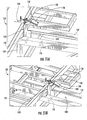
- the board to be placed is to span perpendicularly two parallel boards that are already clamped or otherwise secured in position.
- the articulating arm unit 300 instead of immediately placing the board perpendicular to the two original boards, the articulating arm unit 300 positions the board 900 at an oblique angle to the original boards 902, 904 (see Figure 21A ).
- the board 900 Once the board 900 has been so placed, it can be rotated into a perpendicular orientation (much in the manner that a board might be inserted manually under similar circumstances - see Figure 21B ).
- This technique can facilitate the placement of boards in tight spaces, particularly given the inconsistency of dimensions, straightness, quality, etc., that can appear in wooden boards.
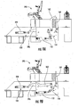
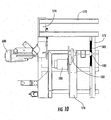
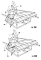
- the articulating arm unit 300 has sufficient length to reach the top and bottom planks of a wall panel and some areas of the wall panel, but in many instances the overall length of the wall panel to be constructed exceeds the reach of the articulating arm unit 300. In such an instance, the system can "inchworm" a partially assembled wall panel away from the articulating arm unit 300 to enable additional areas of the wall panel to be assembled. As the initial portion of the wall panel is assembled, the top and bottom planks are secured in place by the top and bottom plank clamping units 130 (see Figure 20A ). When the partial assembly is to be moved, the controller 500 signals the puller clamps 190 on the movable table section 170 to clamp onto the top and bottom planks.
- the controller signals the clamps 130 on the stationary section 120 to release (see Figure 20B ).
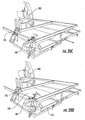
- the movable table section 170 (driven by the rack-and-pinion mechanism via the servomotor 180) then moves away from the articulating arm unit 300, drawing the partially assembled wall panel with it (see Figure 20C ). If (as is typically the case), the wall panel needs to be moved further, the clamps 130 on the stationary table section 120 clamp the top and bottom planks, the puller clamps 190 release ( see Figure 20D ), and the movable table section 170 moves back toward the articulating arm unit 300.
- the system may employ "pinch" rollers that engage one or more of the boards and move a subassembly relative to the stationary table section. Such rollers may also serve to clamp the boards in place during nailing. Other alternatives may also be suitable.
- the controller 500 will often direct the system 100 to move the movable table section 170 so that the nailers 600 mounted thereto are positioned to insert nails through the top and bottom planks into the appropriate studs.
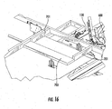
- the system 100 has the capacity to enable boards themselves to serve as "fixtures” for other boards, even if the "fixturing” board has not yet been fastened to another board with a nail.
- a rough opening may include "cripples" 701 above a header sub-assembly ( see Figure 16 ).
- two or more top "cripples” 701 may be positioned prior to the positioning of the header board 703.
- the presence of the cripples 701 provides a natural rigid locating reference for the header board 703, after which the header board 703 can be nailed to the cripples 701.
- "trimmer" boards positioned after the header boards can be employed to push the header board into a more accurate position.
- a rough opening such as a window
- two studs be positioned very closely together.
- a "king stud" 800 may be attached to a header when another stud 802 is within 10 inches or so of the king stud 800.
- Figure 19 illustrates an exemplary process algorithm for the controller 500 to follow in directing the construction of a wall panel.
- the controller receives a data file of a wall panel ( block 902 ), typically from a CAD drawing or the like.
- the controller determines the top left and bottom right positions of each board ( block 904 ), then calculates the board size, length, orientation and/or use and the board' front, right and center position data ( block 906 ).
- the board source is identified (i.e., rack or saw)( block 908 ), and the board data is sorted to create a nominal build sequence ( block 910 ).
- Boards are grouped according to their association with a rough opening, as these may be treated differently (block 912 ). After this grouping, the board sequence may be re-ordered to capitalize on certain nailing opportunities, such as self-fixturing, nails that on different boards that are near each other, and the like ( block 914 ).
- Assembly begins with the selection of a board ( block 916 ).
- the nailing requirements of the board are determined based on its use and location ( block 918 ).
- the board is then retrieved from the source ( block 920 ).
- the controller 500 determines whether any movement of the movable carriage 170 is required ( e.g ., whether the top and bottom planks should be moved, or if the pusher clamps 192 may be called for)( block 922 ).
- the nominal motion path for the board is then adjusted if necessary, taking into account parameters such as the size and orientation of the board and potential interference with other boards or fixtures ( block 924 ). Any movement of the movable carriage 170 then occurs, as does any needed clamping, and the board is positioned ( block 926 ).
- any nailing is to be performed prior to the selection of the next board, it occurs next ( block 928 ). This step may also include movement of the movable carriage 170 (particularly if the pusher clamps 192 are used), and setting of clamps.
- the controller determines if the wall panel is complete ( block 930 ), and if it is not, the process loops back to block 916 for the addition of more boards.
- each block in the flow charts or block diagrams represents a module, segment, or portion of code, which comprises one or more executable instructions for implementing the specified logical function(s).
- the functions noted in the blocks may occur out of the order noted in the figures, or some functions may be omitted.
- two blocks shown in succession may in fact be executed substantially concurrently or the blocks may sometimes be executed in the reverse order, depending upon the functionality involved.
Landscapes
- Engineering & Computer Science (AREA)
- Architecture (AREA)
- Mechanical Engineering (AREA)
- Life Sciences & Earth Sciences (AREA)
- Forests & Forestry (AREA)
- Physics & Mathematics (AREA)
- Electromagnetism (AREA)
- Civil Engineering (AREA)
- Structural Engineering (AREA)
- Robotics (AREA)
- Conveying And Assembling Of Building Elements In Situ (AREA)
Claims (14)
- Système (100) destiné à construire des panneaux muraux qui comprennent une pluralité d'éléments de structure, le système (100) comprenant :une source (400) d'éléments de structure d'une taille prédéterminée ;une table horizontale (110) configurée de façon à supporter des planches quand elles sont formées en un panneau mural, la table (110) comprenant une section fixe (120) et un chariot mobile (170) qui est configuré de façon à se déplacer dans une direction longitudinale vers la section fixe (120) et en s'éloignant de celle-ci ; etune unité à bras articulé (300) qui présente un dispositif de préhension (201), caractérisé en ce que l'unité à bras articulé (300) est positionnée de façon à rechercher des planches à partir de la source (400) à l'aide du dispositif de préhension (201) et à les placer sur la table (110) ; et le système comprend en outre :au moins une première unité de serrage (130) montée sur la section fixe (120) destinée à serrer les éléments de structure sur celle-ci ;au moins une deuxième unité de serrage (190) montée sur le chariot mobile (170) destinée à serrer les éléments de structure sur celui-ci ; etun contrôleur (500) qui commande le déplacement de l'unité à bras articulé (300) et du chariot mobile (170).
- Système selon la revendication 1, dans lequel la première unité de serrage (130) est positionnée de façon à serrer l'un des éléments de structure supérieur et inférieur du panneau mural, et la deuxième unité de serrage (190) est positionnée de façon à serrer l'un des éléments de structure inférieur et supérieur du panneau mural.
- Système selon la revendication 1, dans lequel les éléments de structure sont des planches en bois, et dans lequel le chariot mobile (170) comprend au moins une unité de clouage (242).
- Système selon la revendication 4, dans lequel l'unité de clouage (242) est réglable en profondeur.
- Système selon la revendication 1, dans lequel les première et deuxième unités de serrage (130, 190) sont réglables en profondeur.
- Système selon la revendication 1, dans lequel le chariot mobile (170) comprend au moins une troisième unité de serrage (192) configurée de façon à serrer une planche qui s'étend de manière transversale.
- Système selon la revendication 1, dans lequel le chariot mobile comprend un mécanisme de poussée configuré de façon à pousser un élément de structure de manière longitudinale lorsque le chariot mobile (170) se déplace par rapport à l'unité à bras articulé (300).
- Système selon la revendication 1, dans lequel les première (130) et deuxième (190) unités de serrage sont montées sur la table (110) de telle sorte que leurs positions puissent être réglées de manière transversale de façon à recevoir la construction de panneaux muraux de différentes tailles.
- Système selon la revendication 1, dans lequel l'unité à bras articulé (300) comprend en outre une cloueuse (242).
- Procédé de construction d'un panneau mural qui comprend une pluralité d'éléments de structure, comprenant les étapes consistant à :(a) fournir une table horizontale (110) configurée de façon à supporter des éléments de structure quand ils sont formés en un panneau mural, la table (110) comprenant une section fixe (120) et un chariot mobile (170) qui est configuré de façon à se déplacer dans une direction longitudinale par rapport à la section fixe (120) ;
dans lequel une première unité de serrage (130) au moins est montée sur la section fixe (120), destinée à serrer les éléments de structure sur celle-ci ; caractérisé en ce qu'une deuxième unité de serrage (190) au moins est montée sur le chariot mobile (170), destinée à serrer les éléments de structure sur celui-ci ; et le système comprend en outre les étapes consistant à :(b) former un sous-ensemble d'éléments de structure, dans lequel un élément de structure au moins est serré avec les premières unités de serrage (130) ;(c) serrer l'élément de structure avec la deuxième unité de serrage (190) ;(d) libérer les premières unités de serrage (130) ; et(e) déplacer le chariot mobile (170) par rapport à la section table fixe (120) de façon à déplacer le sous-ensemble par rapport à la section table fixe (120). - Procédé selon la revendication 10, comprenant en outre les étapes consistant à :(f) serrer la planche avec la première unité de serrage (130) ; et(g) libérer la planche de la deuxième unité de serrage (190).
- Procédé selon la revendication 11, comprenant la répétition des étapes (c) à (g) de façon à déplacer encore le sous-ensemble par rapport à la section table fixe (120).
- Procédé selon la revendication 10, dans lequel les éléments de structure sont des planches en bois, et comprenant en outre une étape consistant à clouer deux planches ensemble entre les étapes (e) et (f).
- Procédé selon la revendication 13, comprenant en outre une étape consistant à doter une unité à bras articulé (300) d'une cloueuse (242) ; et
dans lequel l'étape de clouage comprend une étape consistant à clouer les planches ensemble à l'aide de la cloueuse (242).
Applications Claiming Priority (2)
| Application Number | Priority Date | Filing Date | Title |
|---|---|---|---|
| US38719210P | 2010-09-28 | 2010-09-28 | |
| PCT/US2011/053347 WO2012047603A1 (fr) | 2010-09-28 | 2011-09-27 | Appareil automatisé pour la construction d'ensembles d'éléments de bâtiment |
Publications (3)
| Publication Number | Publication Date |
|---|---|
| EP2621691A1 EP2621691A1 (fr) | 2013-08-07 |
| EP2621691A4 EP2621691A4 (fr) | 2014-05-21 |
| EP2621691B1 true EP2621691B1 (fr) | 2015-03-04 |
Family
ID=45928073
Family Applications (1)
| Application Number | Title | Priority Date | Filing Date |
|---|---|---|---|
| EP11831261.0A Active EP2621691B1 (fr) | 2010-09-28 | 2011-09-27 | Appareil automatisé pour la construction d'ensembles d'éléments de bâtiment |
Country Status (6)
| Country | Link |
|---|---|
| US (2) | US9353519B2 (fr) |
| EP (1) | EP2621691B1 (fr) |
| AU (1) | AU2011312567B2 (fr) |
| CA (2) | CA2891008C (fr) |
| NZ (1) | NZ608181A (fr) |
| WO (1) | WO2012047603A1 (fr) |
Families Citing this family (25)
| Publication number | Priority date | Publication date | Assignee | Title |
|---|---|---|---|---|
| US10329863B2 (en) * | 2013-08-06 | 2019-06-25 | A&O Technologies LLC | Automatic driller |
| ITUB20152514A1 (it) * | 2015-07-27 | 2017-01-27 | Gestind S P A | Stazione automatica per spillare un elemento a membrana a un supporto e relativo metodo |
| US10799677B2 (en) | 2016-03-21 | 2020-10-13 | Edwards Lifesciences Corporation | Multi-direction steerable handles for steering catheters |
| EP3485112B1 (fr) | 2016-07-15 | 2021-08-25 | Fastbrick IP Pty Ltd | Véhicule qui incorpore une machine à poser les briques |
| US10865578B2 (en) | 2016-07-15 | 2020-12-15 | Fastbrick Ip Pty Ltd | Boom for material transport |
| CN111095355B (zh) | 2017-07-05 | 2023-10-20 | 快砖知识产权私人有限公司 | 实时定位和定向跟踪器 |
| MX2017009909A (es) * | 2017-07-31 | 2019-02-08 | German Becerril Hernandez | Sistema automatizado de construccion robotizado y metodo de construccion. |
| CN111213098B (zh) | 2017-08-17 | 2024-03-15 | 快砖知识产权私人有限公司 | 用于交互系统的通信系统 |
| WO2019033170A1 (fr) | 2017-08-17 | 2019-02-21 | Fastbrick Ip Pty Ltd | Dispositif de poursuite laser à mesure d'angle de roulis améliorée |
| US11007921B2 (en) * | 2017-10-03 | 2021-05-18 | Build Ip Llc | Wheeled assembly for item transport |
| CN111212799B (zh) | 2017-10-11 | 2023-04-14 | 快砖知识产权私人有限公司 | 用于传送物体的机器以及与其一起使用的多隔间转盘 |
| US10945844B2 (en) | 2018-10-10 | 2021-03-16 | Edwards Lifesciences Corporation | Heart valve sealing devices and delivery devices therefor |
| US11613041B1 (en) | 2018-11-08 | 2023-03-28 | Scepaniak IP Holdings, LLC | Coping nailer |
| CN113423901A (zh) | 2019-02-14 | 2021-09-21 | 500集团有限公司 | 具有公用通道和叠层围护结构的可折叠建筑结构 |
| US11800695B2 (en) * | 2019-11-14 | 2023-10-24 | Google Llc | Memory insertion machine |
| US11911911B2 (en) * | 2020-04-08 | 2024-02-27 | Smart Building Tech Co., Ltd. | Near-site robotic construction system and method for prefabrications of construction components |
| US20210316459A1 (en) * | 2020-04-08 | 2021-10-14 | Smart Building Tech Co., Ltd. | Cloud based computer-implemented system and method for computer-assisted planning and simulation of robot motions in construction |
| CN111774616B (zh) * | 2020-06-30 | 2023-09-12 | 中航成飞民用飞机有限责任公司 | 三维投影辅助装配工装 |
| EP4178739A1 (fr) * | 2020-07-13 | 2023-05-17 | House of Design LLC | Systèmes et procédés d'assemblage de sous-composants, de sous-éléments et d'éléments de construction |
| US11718984B2 (en) | 2021-01-12 | 2023-08-08 | Build Ip Llc | Liftable foldable transportable buildings |
| US11739547B2 (en) | 2021-01-12 | 2023-08-29 | Build Ip Llc | Stackable foldable transportable buildings |
| USD981596S1 (en) * | 2021-08-05 | 2023-03-21 | Agorus, Inc. | Construction panel |
| CN113580079A (zh) * | 2021-08-17 | 2021-11-02 | 滁州市朝友精密制造有限公司 | 一种钣金焊接六轴机械手用翻转操作台 |
| WO2023122332A1 (fr) * | 2021-12-23 | 2023-06-29 | BotBuilt, Inc. | Systèmes et procédés pour un effecteur terminal de connecteur de plaque à goujon |
| WO2024011331A1 (fr) * | 2022-07-14 | 2024-01-18 | Promise Robotics Inc. | Procédés, systèmes et dispositifs d'assemblage automatisé de structures de bâtiment |
Family Cites Families (23)
| Publication number | Priority date | Publication date | Assignee | Title |
|---|---|---|---|---|
| US2983292A (en) * | 1959-01-20 | 1961-05-09 | Pagebar Inc | Clamp table for fabricating a roof truss |
| US3592376A (en) | 1970-01-08 | 1971-07-13 | Hydro Air Eng Inc | Apparatus for prefabricating wooden panel frames |
| US3789101A (en) * | 1971-04-30 | 1974-01-29 | Thomas 1970 Trust | Panel manufacturing machine and method |
| US3877132A (en) * | 1973-08-03 | 1975-04-15 | Marion O Fogle | Machine for assembling structures such as frames |
| US4620658A (en) | 1982-12-31 | 1986-11-04 | Textron, Inc. | Assembly of frames |
| US4567821A (en) * | 1984-06-08 | 1986-02-04 | Mcdonald William D | Apparatus for assembling wooden trusses and the like |
| NZ225505A (en) * | 1987-07-22 | 1991-11-26 | Tonny Ernst Bergqvist | Press for manufacture of foamed plastics panels |
| US5095605A (en) * | 1989-09-06 | 1992-03-17 | Tonus Egidio L | Method for making pallets |
| US5341556A (en) * | 1991-06-28 | 1994-08-30 | The United States Of America As Represented By The Secretary Of The Air Force | Method and apparatus for manufacture of reinforced panels |
| US5555617A (en) * | 1994-10-07 | 1996-09-17 | Pope; Harold W. | Pallet manufacturing apparatus |
| US5947460A (en) * | 1995-11-02 | 1999-09-07 | Tee-Lok Corporation | Truss table with integrated positioning stops |
| US6058601A (en) * | 1998-07-27 | 2000-05-09 | Dekoning; Hubertus C. M. | Apparatus for automatic fence panel assembly |
| US6539830B1 (en) | 1999-10-13 | 2003-04-01 | The Koskovich Company | Automated board processing apparatus |
| US6523243B2 (en) * | 2000-03-24 | 2003-02-25 | Hinchcliff Lumber Company | Apparatus and process for boring and bolting pallets |
| IT1319867B1 (it) | 2000-05-11 | 2003-11-03 | Giuseppe Raffoni | Sistema automatizzato e mezzi per l'alimentazione dei listelli nelleapparecchiature che realizzano cornici rettangolari. |
| SE520106C2 (sv) * | 2000-12-15 | 2003-05-27 | Randek Maskin Ab | Matningsanordning |
| FI118419B (fi) * | 2005-06-23 | 2007-11-15 | Matti Turulin | Menetelmä ja järjestelmä kattoristikoiden tai sentapaisten rakenteiden valmistamiseksi |
| US7610668B2 (en) * | 2006-04-04 | 2009-11-03 | Great Dane Limited Partnership | Automated sidewall assembly machine |
| US20080172983A1 (en) * | 2007-01-23 | 2008-07-24 | Urmson James F | System and method for the automated assembly of trusses |
| US8478436B2 (en) * | 2008-07-31 | 2013-07-02 | Illinois Tool Works Inc. | Apparatus, method and computer program product for providing automated truss assembly |
| US8185240B2 (en) * | 2008-08-29 | 2012-05-22 | Williams Robotics, Llc | Automated apparatus for constructing assemblies of building components |
| US20100061829A1 (en) * | 2008-09-11 | 2010-03-11 | Mcadoo David L | System and apparatus for progressive robotic truss assembly |
| US9609782B2 (en) * | 2013-01-15 | 2017-03-28 | Intel Corporation | Rack assembly structure |
-
2011
- 2011-09-27 NZ NZ608181A patent/NZ608181A/en unknown
- 2011-09-27 AU AU2011312567A patent/AU2011312567B2/en active Active
- 2011-09-27 CA CA2891008A patent/CA2891008C/fr active Active
- 2011-09-27 US US13/988,705 patent/US9353519B2/en active Active
- 2011-09-27 CA CA2811420A patent/CA2811420C/fr active Active
- 2011-09-27 WO PCT/US2011/053347 patent/WO2012047603A1/fr active Application Filing
- 2011-09-27 EP EP11831261.0A patent/EP2621691B1/fr active Active
-
2016
- 2016-05-25 US US15/164,564 patent/US10189176B2/en active Active
Also Published As
| Publication number | Publication date |
|---|---|
| EP2621691A1 (fr) | 2013-08-07 |
| AU2011312567A1 (en) | 2013-04-11 |
| EP2621691A4 (fr) | 2014-05-21 |
| US20130283618A1 (en) | 2013-10-31 |
| US20160263767A1 (en) | 2016-09-15 |
| US10189176B2 (en) | 2019-01-29 |
| CA2811420A1 (fr) | 2012-04-12 |
| NZ608181A (en) | 2015-03-27 |
| CA2811420C (fr) | 2015-09-01 |
| US9353519B2 (en) | 2016-05-31 |
| AU2011312567B2 (en) | 2015-12-24 |
| WO2012047603A1 (fr) | 2012-04-12 |
| CA2891008C (fr) | 2019-05-07 |
| CA2891008A1 (fr) | 2012-04-12 |
Similar Documents
| Publication | Publication Date | Title |
|---|---|---|
| US10189176B2 (en) | Automated apparatus for constructing assemblies of building components | |
| CA2735144C (fr) | Appareil automatique pour construire des ensembles de composants de batiment | |
| Kunic et al. | Design and assembly automation of the Robotic Reversible Timber Beam | |
| EP2629941B1 (fr) | Manipulateur mobile auto-reconfigurable | |
| JP6914475B2 (ja) | ワーク把持装置 | |
| EP2381324A1 (fr) | Procédé de commande du fonctionnement d'une machine pour le travail du bois ou d'un matériau analogue | |
| JPH07284936A (ja) | 複数部材結合装置と複数部材結合装置の自動溶接シ ステム | |
| da Costa | Dassault adaptive cells | |
| CN114905595A (zh) | 一种建筑施工模板的预加工设备及加工控制方法 | |
| Lee et al. | Operational space control under actuator bandwidth limitation | |
| CN108723758B (zh) | 打螺母机 | |
| US20240091982A1 (en) | Automated wall frame assembly system | |
| EP3967469B1 (fr) | Dispositif d'assemblage pour la fabrication d'un ensemble panneau | |
| Storiale et al. | Planning of efficient trajectories in robotized assembly of aerostructures exploiting kinematic redundancy | |
| CN213197581U (zh) | 一种可夹持铣刀和销钉的机械手及锣机 | |
| US20230226695A1 (en) | Systems and methods for automated framing construction | |
| JP2018518743A (ja) | 機械加工の方法、および、装置 | |
| Isaksson | Drilling with force feedback | |
| Petko et al. | A new 3-DOF parallel manipulator | |
| Phillips | Flexible fabrication of structural roof panels: process layout and assembly equipment development | |
| JPS6227802A (ja) | 工業用ロボツトのハンド制御装置及び制御方法 |
Legal Events
| Date | Code | Title | Description |
|---|---|---|---|
| PUAI | Public reference made under article 153(3) epc to a published international application that has entered the european phase |
Free format text: ORIGINAL CODE: 0009012 |
|
| 17P | Request for examination filed |
Effective date: 20130402 |
|
| AK | Designated contracting states |
Kind code of ref document: A1 Designated state(s): AL AT BE BG CH CY CZ DE DK EE ES FI FR GB GR HR HU IE IS IT LI LT LU LV MC MK MT NL NO PL PT RO RS SE SI SK SM TR |
|
| DAX | Request for extension of the european patent (deleted) | ||
| A4 | Supplementary search report drawn up and despatched |
Effective date: 20140422 |
|
| RIC1 | Information provided on ipc code assigned before grant |
Ipc: B27F 7/02 20060101AFI20140414BHEP |
|
| GRAP | Despatch of communication of intention to grant a patent |
Free format text: ORIGINAL CODE: EPIDOSNIGR1 |
|
| INTG | Intention to grant announced |
Effective date: 20140912 |
|
| GRAS | Grant fee paid |
Free format text: ORIGINAL CODE: EPIDOSNIGR3 |
|
| GRAA | (expected) grant |
Free format text: ORIGINAL CODE: 0009210 |
|
| AK | Designated contracting states |
Kind code of ref document: B1 Designated state(s): AL AT BE BG CH CY CZ DE DK EE ES FI FR GB GR HR HU IE IS IT LI LT LU LV MC MK MT NL NO PL PT RO RS SE SI SK SM TR |
|
| REG | Reference to a national code |
Ref country code: GB Ref legal event code: FG4D |
|
| REG | Reference to a national code |
Ref country code: CH Ref legal event code: EP |
|
| REG | Reference to a national code |
Ref country code: IE Ref legal event code: FG4D |
|
| REG | Reference to a national code |
Ref country code: AT Ref legal event code: REF Ref document number: 713431 Country of ref document: AT Kind code of ref document: T Effective date: 20150415 |
|
| REG | Reference to a national code |
Ref country code: DE Ref legal event code: R096 Ref document number: 602011014492 Country of ref document: DE Effective date: 20150416 |
|
| REG | Reference to a national code |
Ref country code: AT Ref legal event code: MK05 Ref document number: 713431 Country of ref document: AT Kind code of ref document: T Effective date: 20150304 Ref country code: NL Ref legal event code: VDEP Effective date: 20150304 |
|
| PG25 | Lapsed in a contracting state [announced via postgrant information from national office to epo] |
Ref country code: HR Free format text: LAPSE BECAUSE OF FAILURE TO SUBMIT A TRANSLATION OF THE DESCRIPTION OR TO PAY THE FEE WITHIN THE PRESCRIBED TIME-LIMIT Effective date: 20150304 Ref country code: NO Free format text: LAPSE BECAUSE OF FAILURE TO SUBMIT A TRANSLATION OF THE DESCRIPTION OR TO PAY THE FEE WITHIN THE PRESCRIBED TIME-LIMIT Effective date: 20150604 Ref country code: FI Free format text: LAPSE BECAUSE OF FAILURE TO SUBMIT A TRANSLATION OF THE DESCRIPTION OR TO PAY THE FEE WITHIN THE PRESCRIBED TIME-LIMIT Effective date: 20150304 Ref country code: SE Free format text: LAPSE BECAUSE OF FAILURE TO SUBMIT A TRANSLATION OF THE DESCRIPTION OR TO PAY THE FEE WITHIN THE PRESCRIBED TIME-LIMIT Effective date: 20150304 Ref country code: LT Free format text: LAPSE BECAUSE OF FAILURE TO SUBMIT A TRANSLATION OF THE DESCRIPTION OR TO PAY THE FEE WITHIN THE PRESCRIBED TIME-LIMIT Effective date: 20150304 Ref country code: ES Free format text: LAPSE BECAUSE OF FAILURE TO SUBMIT A TRANSLATION OF THE DESCRIPTION OR TO PAY THE FEE WITHIN THE PRESCRIBED TIME-LIMIT Effective date: 20150304 |
|
| REG | Reference to a national code |
Ref country code: LT Ref legal event code: MG4D |
|
| PG25 | Lapsed in a contracting state [announced via postgrant information from national office to epo] |
Ref country code: GR Free format text: LAPSE BECAUSE OF FAILURE TO SUBMIT A TRANSLATION OF THE DESCRIPTION OR TO PAY THE FEE WITHIN THE PRESCRIBED TIME-LIMIT Effective date: 20150605 Ref country code: RS Free format text: LAPSE BECAUSE OF FAILURE TO SUBMIT A TRANSLATION OF THE DESCRIPTION OR TO PAY THE FEE WITHIN THE PRESCRIBED TIME-LIMIT Effective date: 20150304 Ref country code: LV Free format text: LAPSE BECAUSE OF FAILURE TO SUBMIT A TRANSLATION OF THE DESCRIPTION OR TO PAY THE FEE WITHIN THE PRESCRIBED TIME-LIMIT Effective date: 20150304 Ref country code: AT Free format text: LAPSE BECAUSE OF FAILURE TO SUBMIT A TRANSLATION OF THE DESCRIPTION OR TO PAY THE FEE WITHIN THE PRESCRIBED TIME-LIMIT Effective date: 20150304 |
|
| PG25 | Lapsed in a contracting state [announced via postgrant information from national office to epo] |
Ref country code: NL Free format text: LAPSE BECAUSE OF FAILURE TO SUBMIT A TRANSLATION OF THE DESCRIPTION OR TO PAY THE FEE WITHIN THE PRESCRIBED TIME-LIMIT Effective date: 20150304 |
|
| PG25 | Lapsed in a contracting state [announced via postgrant information from national office to epo] |
Ref country code: PT Free format text: LAPSE BECAUSE OF FAILURE TO SUBMIT A TRANSLATION OF THE DESCRIPTION OR TO PAY THE FEE WITHIN THE PRESCRIBED TIME-LIMIT Effective date: 20150706 Ref country code: CZ Free format text: LAPSE BECAUSE OF FAILURE TO SUBMIT A TRANSLATION OF THE DESCRIPTION OR TO PAY THE FEE WITHIN THE PRESCRIBED TIME-LIMIT Effective date: 20150304 Ref country code: EE Free format text: LAPSE BECAUSE OF FAILURE TO SUBMIT A TRANSLATION OF THE DESCRIPTION OR TO PAY THE FEE WITHIN THE PRESCRIBED TIME-LIMIT Effective date: 20150304 Ref country code: SK Free format text: LAPSE BECAUSE OF FAILURE TO SUBMIT A TRANSLATION OF THE DESCRIPTION OR TO PAY THE FEE WITHIN THE PRESCRIBED TIME-LIMIT Effective date: 20150304 Ref country code: RO Free format text: LAPSE BECAUSE OF FAILURE TO SUBMIT A TRANSLATION OF THE DESCRIPTION OR TO PAY THE FEE WITHIN THE PRESCRIBED TIME-LIMIT Effective date: 20150304 |
|
| PG25 | Lapsed in a contracting state [announced via postgrant information from national office to epo] |
Ref country code: IS Free format text: LAPSE BECAUSE OF FAILURE TO SUBMIT A TRANSLATION OF THE DESCRIPTION OR TO PAY THE FEE WITHIN THE PRESCRIBED TIME-LIMIT Effective date: 20150704 Ref country code: PL Free format text: LAPSE BECAUSE OF FAILURE TO SUBMIT A TRANSLATION OF THE DESCRIPTION OR TO PAY THE FEE WITHIN THE PRESCRIBED TIME-LIMIT Effective date: 20150304 |
|
| REG | Reference to a national code |
Ref country code: DE Ref legal event code: R097 Ref document number: 602011014492 Country of ref document: DE |
|
| PLBE | No opposition filed within time limit |
Free format text: ORIGINAL CODE: 0009261 |
|
| STAA | Information on the status of an ep patent application or granted ep patent |
Free format text: STATUS: NO OPPOSITION FILED WITHIN TIME LIMIT |
|
| PG25 | Lapsed in a contracting state [announced via postgrant information from national office to epo] |
Ref country code: DK Free format text: LAPSE BECAUSE OF FAILURE TO SUBMIT A TRANSLATION OF THE DESCRIPTION OR TO PAY THE FEE WITHIN THE PRESCRIBED TIME-LIMIT Effective date: 20150304 |
|
| 26N | No opposition filed |
Effective date: 20151207 |
|
| PG25 | Lapsed in a contracting state [announced via postgrant information from national office to epo] |
Ref country code: SI Free format text: LAPSE BECAUSE OF FAILURE TO SUBMIT A TRANSLATION OF THE DESCRIPTION OR TO PAY THE FEE WITHIN THE PRESCRIBED TIME-LIMIT Effective date: 20150304 |
|
| PG25 | Lapsed in a contracting state [announced via postgrant information from national office to epo] |
Ref country code: LU Free format text: LAPSE BECAUSE OF FAILURE TO SUBMIT A TRANSLATION OF THE DESCRIPTION OR TO PAY THE FEE WITHIN THE PRESCRIBED TIME-LIMIT Effective date: 20150927 Ref country code: MC Free format text: LAPSE BECAUSE OF FAILURE TO SUBMIT A TRANSLATION OF THE DESCRIPTION OR TO PAY THE FEE WITHIN THE PRESCRIBED TIME-LIMIT Effective date: 20150304 |
|
| REG | Reference to a national code |
Ref country code: CH Ref legal event code: PL |
|
| REG | Reference to a national code |
Ref country code: IE Ref legal event code: MM4A |
|
| PG25 | Lapsed in a contracting state [announced via postgrant information from national office to epo] |
Ref country code: LI Free format text: LAPSE BECAUSE OF NON-PAYMENT OF DUE FEES Effective date: 20150930 Ref country code: CH Free format text: LAPSE BECAUSE OF NON-PAYMENT OF DUE FEES Effective date: 20150930 Ref country code: IE Free format text: LAPSE BECAUSE OF NON-PAYMENT OF DUE FEES Effective date: 20150927 |
|
| PG25 | Lapsed in a contracting state [announced via postgrant information from national office to epo] |
Ref country code: BE Free format text: LAPSE BECAUSE OF FAILURE TO SUBMIT A TRANSLATION OF THE DESCRIPTION OR TO PAY THE FEE WITHIN THE PRESCRIBED TIME-LIMIT Effective date: 20150304 |
|
| REG | Reference to a national code |
Ref country code: FR Ref legal event code: PLFP Year of fee payment: 6 |
|
| PG25 | Lapsed in a contracting state [announced via postgrant information from national office to epo] |
Ref country code: MT Free format text: LAPSE BECAUSE OF FAILURE TO SUBMIT A TRANSLATION OF THE DESCRIPTION OR TO PAY THE FEE WITHIN THE PRESCRIBED TIME-LIMIT Effective date: 20150304 |
|
| PG25 | Lapsed in a contracting state [announced via postgrant information from national office to epo] |
Ref country code: BG Free format text: LAPSE BECAUSE OF FAILURE TO SUBMIT A TRANSLATION OF THE DESCRIPTION OR TO PAY THE FEE WITHIN THE PRESCRIBED TIME-LIMIT Effective date: 20150304 Ref country code: SM Free format text: LAPSE BECAUSE OF FAILURE TO SUBMIT A TRANSLATION OF THE DESCRIPTION OR TO PAY THE FEE WITHIN THE PRESCRIBED TIME-LIMIT Effective date: 20150304 Ref country code: HU Free format text: LAPSE BECAUSE OF FAILURE TO SUBMIT A TRANSLATION OF THE DESCRIPTION OR TO PAY THE FEE WITHIN THE PRESCRIBED TIME-LIMIT; INVALID AB INITIO Effective date: 20110927 |
|
| PG25 | Lapsed in a contracting state [announced via postgrant information from national office to epo] |
Ref country code: CY Free format text: LAPSE BECAUSE OF FAILURE TO SUBMIT A TRANSLATION OF THE DESCRIPTION OR TO PAY THE FEE WITHIN THE PRESCRIBED TIME-LIMIT Effective date: 20150304 |
|
| REG | Reference to a national code |
Ref country code: FR Ref legal event code: PLFP Year of fee payment: 7 |
|
| PG25 | Lapsed in a contracting state [announced via postgrant information from national office to epo] |
Ref country code: MK Free format text: LAPSE BECAUSE OF FAILURE TO SUBMIT A TRANSLATION OF THE DESCRIPTION OR TO PAY THE FEE WITHIN THE PRESCRIBED TIME-LIMIT Effective date: 20150304 Ref country code: TR Free format text: LAPSE BECAUSE OF FAILURE TO SUBMIT A TRANSLATION OF THE DESCRIPTION OR TO PAY THE FEE WITHIN THE PRESCRIBED TIME-LIMIT Effective date: 20150304 |
|
| REG | Reference to a national code |
Ref country code: FR Ref legal event code: PLFP Year of fee payment: 8 |
|
| PG25 | Lapsed in a contracting state [announced via postgrant information from national office to epo] |
Ref country code: AL Free format text: LAPSE BECAUSE OF FAILURE TO SUBMIT A TRANSLATION OF THE DESCRIPTION OR TO PAY THE FEE WITHIN THE PRESCRIBED TIME-LIMIT Effective date: 20150304 |
|
| PGFP | Annual fee paid to national office [announced via postgrant information from national office to epo] |
Ref country code: IT Payment date: 20230810 Year of fee payment: 13 Ref country code: GB Payment date: 20230803 Year of fee payment: 13 |
|
| PGFP | Annual fee paid to national office [announced via postgrant information from national office to epo] |
Ref country code: FR Payment date: 20230808 Year of fee payment: 13 Ref country code: DE Payment date: 20230802 Year of fee payment: 13 |