EP2621071A1 - Power conversion device - Google Patents
Power conversion device Download PDFInfo
- Publication number
- EP2621071A1 EP2621071A1 EP10857528.3A EP10857528A EP2621071A1 EP 2621071 A1 EP2621071 A1 EP 2621071A1 EP 10857528 A EP10857528 A EP 10857528A EP 2621071 A1 EP2621071 A1 EP 2621071A1
- Authority
- EP
- European Patent Office
- Prior art keywords
- power
- current
- voltage
- instruction value
- system voltage
- Prior art date
- Legal status (The legal status is an assumption and is not a legal conclusion. Google has not performed a legal analysis and makes no representation as to the accuracy of the status listed.)
- Ceased
Links
Images


Classifications
-
- H—ELECTRICITY
- H02—GENERATION; CONVERSION OR DISTRIBUTION OF ELECTRIC POWER
- H02J—CIRCUIT ARRANGEMENTS OR SYSTEMS FOR SUPPLYING OR DISTRIBUTING ELECTRIC POWER; SYSTEMS FOR STORING ELECTRIC ENERGY
- H02J3/00—Circuit arrangements for ac mains or ac distribution networks
- H02J3/38—Arrangements for parallely feeding a single network by two or more generators, converters or transformers
- H02J3/381—Dispersed generators
-
- H—ELECTRICITY
- H02—GENERATION; CONVERSION OR DISTRIBUTION OF ELECTRIC POWER
- H02M—APPARATUS FOR CONVERSION BETWEEN AC AND AC, BETWEEN AC AND DC, OR BETWEEN DC AND DC, AND FOR USE WITH MAINS OR SIMILAR POWER SUPPLY SYSTEMS; CONVERSION OF DC OR AC INPUT POWER INTO SURGE OUTPUT POWER; CONTROL OR REGULATION THEREOF
- H02M5/00—Conversion of ac power input into ac power output, e.g. for change of voltage, for change of frequency, for change of number of phases
- H02M5/40—Conversion of ac power input into ac power output, e.g. for change of voltage, for change of frequency, for change of number of phases with intermediate conversion into dc
- H02M5/42—Conversion of ac power input into ac power output, e.g. for change of voltage, for change of frequency, for change of number of phases with intermediate conversion into dc by static converters
- H02M5/44—Conversion of ac power input into ac power output, e.g. for change of voltage, for change of frequency, for change of number of phases with intermediate conversion into dc by static converters using discharge tubes or semiconductor devices to convert the intermediate dc into ac
- H02M5/453—Conversion of ac power input into ac power output, e.g. for change of voltage, for change of frequency, for change of number of phases with intermediate conversion into dc by static converters using discharge tubes or semiconductor devices to convert the intermediate dc into ac using devices of a triode or transistor type requiring continuous application of a control signal
- H02M5/458—Conversion of ac power input into ac power output, e.g. for change of voltage, for change of frequency, for change of number of phases with intermediate conversion into dc by static converters using discharge tubes or semiconductor devices to convert the intermediate dc into ac using devices of a triode or transistor type requiring continuous application of a control signal using semiconductor devices only
-
- H—ELECTRICITY
- H02—GENERATION; CONVERSION OR DISTRIBUTION OF ELECTRIC POWER
- H02J—CIRCUIT ARRANGEMENTS OR SYSTEMS FOR SUPPLYING OR DISTRIBUTING ELECTRIC POWER; SYSTEMS FOR STORING ELECTRIC ENERGY
- H02J2300/00—Systems for supplying or distributing electric power characterised by decentralized, dispersed, or local generation
- H02J2300/20—The dispersed energy generation being of renewable origin
- H02J2300/28—The renewable source being wind energy
-
- H—ELECTRICITY
- H02—GENERATION; CONVERSION OR DISTRIBUTION OF ELECTRIC POWER
- H02J—CIRCUIT ARRANGEMENTS OR SYSTEMS FOR SUPPLYING OR DISTRIBUTING ELECTRIC POWER; SYSTEMS FOR STORING ELECTRIC ENERGY
- H02J3/00—Circuit arrangements for ac mains or ac distribution networks
- H02J3/38—Arrangements for parallely feeding a single network by two or more generators, converters or transformers
- H02J3/46—Controlling of the sharing of output between the generators, converters, or transformers
- H02J3/48—Controlling the sharing of the in-phase component
-
- Y—GENERAL TAGGING OF NEW TECHNOLOGICAL DEVELOPMENTS; GENERAL TAGGING OF CROSS-SECTIONAL TECHNOLOGIES SPANNING OVER SEVERAL SECTIONS OF THE IPC; TECHNICAL SUBJECTS COVERED BY FORMER USPC CROSS-REFERENCE ART COLLECTIONS [XRACs] AND DIGESTS
- Y02—TECHNOLOGIES OR APPLICATIONS FOR MITIGATION OR ADAPTATION AGAINST CLIMATE CHANGE
- Y02E—REDUCTION OF GREENHOUSE GAS [GHG] EMISSIONS, RELATED TO ENERGY GENERATION, TRANSMISSION OR DISTRIBUTION
- Y02E10/00—Energy generation through renewable energy sources
- Y02E10/70—Wind energy
- Y02E10/76—Power conversion electric or electronic aspects
Definitions
- the invention relates to a power converter apparatus applied to a wind power generation system.
- a reactive power compensation apparatus such as a static var compensator (SVC) or static synchronous compensator (SATCOM) is provided for stabilization of a system voltage.
- SVC static var compensator
- SATCOM static synchronous compensator
- An object of the invention is to provide a power converter apparatus capable of controlling system voltage stabilization.
- a power converter apparatus that is applied to a wind power generation system and converts power generated by a wind power generator to alternating-current power supplied for a power system
- the power converter apparatus including system voltage detection means for detecting a system voltage of the power system; and control means for stably outputting power generated by the wind power generator to the power system based on a power instruction value from a higher level controller and controlling an output voltage of the power converter apparatus to stabilize the system voltage of the power system based on an alternating-current voltage instruction value in a case where the system voltage detected by the system voltage detection means is within a preset range, and controlling an active current component and a reactive current component of an output current of the power converter apparatus to stabilize the system voltage of the power system by use of a voltage drop due to impedance of the power system in a case where the system voltage detected by the system voltage detection means is outside the preset range.
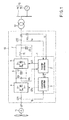
- FIG. 1 is a block diagram showing the structure of a wind power generation system to which a power conditioner 10 according to an embodiment of the invention is applied.
- the same symbols are attached to the portions in the drawings, the detailed explanation thereof is omitted and different portions are mainly described. This applies to the following embodiments and the repetitive explanation is omitted.
- a wind power generation system includes a wind power generator 11, a power conditioner (PCS, Power Conditioning System) 10, an interconnection transformer 12 and a power system 13.
- PCS Power Conditioning System
- the wind power generator 11 is a permanent magnetic synchronous generator (PMSG).
- the wind power generator 11 makes use of wind power to generate electricity.
- the wind power generator 11 when the wind power generator 11 is a PMSG that is directly driven without using a high-speed gear, the wind power generator 11 outputs an alternating-current voltage of 10 to 20 Hz to the power conditioner 10.
- a system bus 14 and a system power supply 15 that supplies power to the system bus 14 are contained in the power system 13.
- the frequency of power generated by the system power supply 15 is 50 or 60 Hz, for example.
- the system bus 14 is connected to the power conditioner 10 via the interconnection transformer 12.
- the power conditioner 10 is a power converter apparatus that converts alternating-current power supplied from the wind power generator 11 to alternating-current power synchronized with system voltage Vr.
- the power conditioner 10 supplies the converted alternating-current power to the power system 13 via the interconnection transformer 12.
- the power conditioner 10 includes a converter 4, a direct-current link 5, an inverter 6, an alternating-current filter 7, a control device 1, an alternating-current detector CT1, an alternating-current detector CT2 and an alternating-current voltage detector PTr.
- the control device 1 includes a converter controller 3 that controls the converter 4 and an inverter controller 2 that controls the inverter 6.
- the alternating-current current detector CT1 is provided on the input side of the power conditioner 10.
- the alternating-current detector CT1 is a detector that measures output current (input current to the converter 4) Ig of the wind power generator 11.
- the alternating-current detector CT1 outputs the detected output current Ig of the wind power generator 11 as a signal to the converter controller 3.
- the alternating-current current detector CT2 is provided on the output side of the power conditioner 10.
- the alternating-current detector CT2 is a detector that measures output current Iiv of the inverter 6.
- the alternating-current detector CT2 outputs the detected output current Iiv of the wind power generator 11 as a signal to the inverter controller 2.
- the alternating-current voltage detector PTr is provided on the output side of the power conditioner 10.
- the alternating-current voltage detector PTr is a detector that measures a voltage on the output side of the power conditioner 10.
- the alternating-current voltage detector PTr outputs the detected voltage as a signal used for measuring system voltage Vr of the power system 13 to the inverter controller 2.
- the alternating-current side of the converter 4 is connected to the wind power generator 11.
- the direct-current side of the converter 4 is connected to the direct-current side of the inverter 6 via the direct-current link 5. That is, the converter 4, the direct-current link 5 and inverter 6 constitute a back-to-back (BTB) converter.
- the alternating-current filter 7 is connected to the output side of the inverter 6.
- the converter 4 converts alternating-current power input from the wind power generator 11 to direct-current power.
- the converter 4 outputs the converted direct-current power to the inverter 6 via the direct-current link 5.
- the direct-current link 5 connects the positive polarities and negative polarities of the converter 4 and inverter 6 to one another.
- a capacitor 51 is connected between the positive polarity and negative polarity of the direct-current link 5. The capacitor 51 smoothes the direct-current power supplied to the direct-current link.
- the inverter 6 converts the direct-current power input from the converter 4 to alternating-current power synchronized with the power system 13.
- the inverter 6 outputs the converted alternating-current power to the interconnection transformer 12 via the alternating-current filter 7.
- the alternating-current filter 7 includes a reactor 71 and capacitor 72.
- the alternating-current filter 7 suppresses harmonic currents flowing out from the inverter 6 to the power system 13.
- the direct-current voltage detector DV is connected between the positive polarity and negative polarity of the direct-current link 5.
- the direct-current voltage detector DV is a detector that measures direct-current voltage (voltage across the capacitor 51) Vdc between the positive polarity and negative polarity of the direct-current link 5.
- the direct-current voltage detector DV outputs the detected direct-current voltage Vdc as a signal to the inverter controller 2.
- the output current Ig of the wind power generator 11 detected by the alternating-current detector CT1 is input to the converter controller 3.
- the converter controller 3 generates gate signal GTc used for controlling the converter 4 based on the output current Ig of the wind power generator 11.
- the converter controller 3 outputs the generated gate signal GTc to the converter 4 and controls the converter 4.
- the converter controller 3 outputs active power instruction value Pr0 used for controlling the inverter 6 to the inverter controller 2.
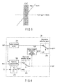
- FIG. 2 is a block diagram showing the structure of the inverter controller 2 according to the embodiment.
- the inverter controller 2 generates gate signal GTi based on the active power instruction value Pr0 input from the converter controller 3, the system voltage Vr detected by the alternating-current voltage detector PTr, the output current Iiv detected by the alternating-current detector CT2, the direct-current voltage Vdc detected by the direct-current voltage detector DV and preset direct-current voltage instruction value Vdcr.
- the inverter controller 2 outputs the generated gate signal GTi to the inverter 6 and controls the inverter 6.
- the inverter controller 2 includes an active current instruction value calculator 21, a direct-current voltage controller 22, an alternating-current voltage controller 23, a system voltage stabilisation controller 24, an adder 25, a phase-locked loop (PLL) 26, a current controller 27 and a pulse width modulation (PWM) controller 28.
- PLL phase-locked loop
- PWM pulse width modulation
- the active power instruction value Pr0 output from the converter controller 3 and the system voltage Vr detected by the alternating-current voltage detector PTr are input to the active current instruction value calculator 21.
- the active current instruction value calculator 21 calculates active current instruction value Idr1 based on the active power instruction value Pr0 and the system voltage Vr.
- the active current instruction value calculator 21 outputs the calculated active current instruction value Idr1 to the system voltage stabilization controller 24.
- the direct-current voltage Vdc detected by the direct-current voltage detector DV is input to the direct-current voltage controller 22.
- the direct-current voltage controller 22 calculates a value used for correcting the direct-current voltage Vdc to follow the preset direct-current voltage instruction value Vdcr.
- the direct-current voltage controller 22 outputs the calculated value to the adder 25.
- An alternating-current voltage instruction value Vrr output from a higher level control system and the system voltage Vr detected by the alternating-current voltage detector PTr are input to the alternating-current voltage controller 23.
- the alternating-current voltage controller 23 calculates reactive current instruction value Iqr1 based on the alternating-current voltage instruction value Vrr and the system voltage Vr.
- the alternating-current voltage controller 23 outputs the calculated reactive current instruction value Iqr1 to the system voltage stabilization controller 24.
- the system voltage stabilization controller 24 controls the inverter 6 to perform a computation to control system voltage stabilization of the power system 13.
- the active current instruction value Idr1 calculated by the active current instruction value calculator 21, the reactive current instruction value Iqr1 calculated by the alternating-current voltage controller 23 and the system voltage Vr detected by the alternating-current voltage detector PTr are input to the system voltage stabilization controller 24.
- the system voltage stabilization controller 24 calculates active current instruction value Idr11 and reactive current instruction value Iqr2 based on the active current instruction value Idr1, the reactive current instruction value Iqr1 and the system voltage Vr.
- the system voltage stabilization controller 24 outputs the calculated active current instruction value Idr11 to the adder 25.
- the system voltage stabilization controller 24 outputs the calculated reactive current instruction value Iqr2 to the current controller 27.
- the adder 25 adds together the active current instruction value Idr11 input from the voltage stabilization controller 24 and the value input from the direct-current voltage controller 22.
- the adder 25 outputs the sum as active current instruction value Idr2 to the current controller 27.
- the system voltage Vr detected by the alternating-current voltage detector PTr is input to the PLL 26.
- the PLL 26 calculates phase angle ⁇ to attain synchronization with the system voltage Vr based on the system voltage Vr.
- the PLL 26 outputs the calculated phase angle ⁇ to the current controller 27 and the PWM controller 28.
- the system voltage Vr detected by the alternating-current voltage detector PTr, the output current Iiv detected by the alternating-current detector CT2, the active current instruction value Idr2 calculated by the adder 25, the reactive current instruction value Iqr2 calculated by the system voltage stabilization controller 24 and the phase angle ⁇ calculated by the PLL 26 are input to the current controller 27.
- the current controller 27 calculates output voltage instruction value Vivr used as a control instruction with respect to an output voltage of the inverter 6 to cause the output current Iiv of the inverter 6 to follow the active current instruction value Idr2 and the reactive current instruction value Iqr2.
- the current controller 27 outputs the calculated output voltage instruction value Vivr to the PWM controller 28.
- the phase angle ⁇ calculated by the PLL 26 and the output voltage instruction value Vivr calculated by the current controller 27 are input to the PWM controller 28.
- the PWM controller 28 generates gate signal GTi used for controlling the inverter 6 based on the phase angle ⁇ and the output voltage instruction value Vivr.
- the PWM controller 28 outputs the generated gate signal GTi to the inverter 6.
- FIG. 3 is a characteristic diagram showing a system voltage stabilization control table used in the system voltage stabilization controller 24 according to the embodiment.
- the abscissa represents system voltage variation rate ⁇ Vr (1 - System voltage Vr / Rated voltage Vn).
- the ordinate represents current (pu value: /Rated current).
- a system voltage stabilization control table shown in FIG. 3 is implemented in the system voltage stabilization controller 24.
- reactive current instruction value Iqr10 corresponding to the system voltage variation rate ⁇ Vr is determined.
- dead zone Rdz with respect to system voltage variation rate ⁇ Vr is provided. For example, the dead zone Rdz is set within ⁇ 10% with respect to the rated voltage Vr.
- the system voltage stabilization controller 24 calculates the active current instruction value Idr11 and the reactive current instruction value Iqr2 based on the active current instruction value Idr1 and reactive current instruction value Iqr1.
- the system voltage stabilization controller 24 calculates the active current instruction value Idr11 and the reactive current instruction value Iqr2 based on the system voltage variation rate ⁇ Vr by use of the system voltage stabilization control table.
- FIG. 4 is a block diagram showing the structure of the system voltage stabilization controller 24 according to the embodiment.
- the system voltage stabilization controller 24 includes an active current limiter 241, a reactive current limiter 242, a system voltage stabilization control table 243, a reactive current changeover switch 244, an active current instruction value calculator 245 and an active current changeover switch 246.
- the two changeover switches 244, 246 select the upper side. In a case where the system voltage variation rate ⁇ Vr is deviated from the dead zone Rdz, the changeover switches 244, 246 are switched to select the lower side according to a dead zone detection signal indicating that the system voltage variation rate ⁇ Vr is present outside the dead zone Rdz.
- the system voltage stabilization controller 24 performs the following control operation.
- the active current instruction value Idr1 is input to the active current limiter 241.
- the active current limiter 241 limits the active current instruction value Idr1 to a range in which the value can be output from the inverter 6.
- the active current limiter 241 inputs the limited active current instruction value Idr1 to the upper terminal of the active current changeover switch 246.
- the active current changeover switch 246 outputs the value in which the active current instruction value Idr1 input to the upper terminal is limited as the active current instruction value Idr11 calculated by the system voltage stabilization controller 24.
- the active current instruction value Idr1 and the reactive current instruction value Iqrl are input to the reactive current limiter 242.
- the reactive current limiter 242 limits the reactive current instruction value Iqr1 to preferentially output an active current based on the active current instruction value Idr1.
- the reactive current limiter 242 inputs the limited reactive current instruction value Iqr1 to the upper terminal of the reactive current changeover switch 244.
- the reactive current changeover switch 244 outputs a value in which the reactive current instruction value Iqr1 input to the upper terminal is limited as the reactive current instruction value Iqr2 calculated by the system voltage stabilization controller 24.
- the system voltage stabilization controller 24 performs the following control operation.
- the system voltage Vr is input to the system voltage stabilization control table 243.
- the system voltage stabilization control table 243 calculates the system voltage variation rate ⁇ Vr based on the system voltage Vr.
- the system voltage stabilization control table 243 calculates the reactive current instruction value Iqr10 corresponding to the system voltage variation rate ⁇ Vr according to the characteristic diagram shown in FIG. 4 .
- the system voltage stabilization control table 243 inputs the calculated reactive current instruction value Iqr10 to the lower terminal of the reactive current changeover switch 244.
- the reactive current changeover switch 244 outputs the reactive current instruction value Iqr10 input to the lower terminal as the reactive current instruction value Iqr2 calculated by the system voltage stabilization controller 24. Further, the reactive current changeover switch 244 outputs the reactive current instruction value Iqr10 to the active current instruction value calculator 245.
- the reactive current instruction value Iqr10 is input to the active current instruction value calculator 245 from the reactive current changeover switch 244.
- the active current instruction value calculator 245 calculates active current instruction value Idr10 based on the reactive current instruction value Iqr10.
- the active current instruction value Idr10 is derived according to the equation below.
- the active current instruction value calculator 245 inputs the calculated active current instruction value Idr10 to the lower terminal of the active current changeover switch 246.
- Active current instruction value Idr10 ⁇ (1 - Square of reactive current instruction value Iqr10)
- the active current changeover switch 246 outputs the active current instruction value Idr10 input to the lower terminal as the active current instruction value Idr11 calculated by the system voltage stabilization controller 24.
- FIG. 5 is a schematic view showing a system impedance model used for controlling system voltage stabilization by means of the inverter controller 2 according to the embodiment.
- the inverter controller 2 controls an active current component and a reactive current component of output current Iiv of the inverter 6 to stabilize the system voltage by use of a voltage drop due to the system impedance Zm.
- the system voltage Vr can automatically be controlled to be stabilized by controlling the inverter 6 according to the system voltage stabilization control table in which preset dead zone Rdz is provided.
- the present invention is not limited to the abode-described embodiments, but may be modified in various ways without departing from the scope.
- Various inventions can be realized by appropriately combining the structural elements disclosed in the embodiments. For instance, some of the disclosed structural elements may be deleted. Some structural elements of different embodiments may be combined appropriately.
- a power converter apparatus capable of controlling system voltage stabilization can be provided.
Abstract
Description
- The invention relates to a power converter apparatus applied to a wind power generation system.
- Generally, in a wind power generation system, a reactive power compensation apparatus such as a static var compensator (SVC) or static synchronous compensator (SATCOM) is provided for stabilization of a system voltage.
- Further, a wind power generation facility that controls reactive power by means of an inverter and reactive power compensation apparatus capable of controlling reactive power is disclosed (see Patent Literature 1).
- However, installation of the reactive power compensation apparatus increases the cost of the wind power generation system. Further, a large amount of wind power generation systems are recently introduced and a reduction in the power system stability at the system voltage lowering time are feared. Therefore, it is required for the wind power generation system to have a function of maintaining the system voltage over a wide voltage range. However, normal reactive power control in the conventional wind power generation system is not sufficient as control for stabilizing the system voltage.
-
- Patent Literature 1: Jpn Past. Appln. KOKAI Publication No.
2000-78896 - An object of the invention is to provide a power converter apparatus capable of controlling system voltage stabilization.
- In accordance with an aspect of the invention, there is provided a power converter apparatus that is applied to a wind power generation system and converts power generated by a wind power generator to alternating-current power supplied for a power system, the power converter apparatus including system voltage detection means for detecting a system voltage of the power system; and control means for stably outputting power generated by the wind power generator to the power system based on a power instruction value from a higher level controller and controlling an output voltage of the power converter apparatus to stabilize the system voltage of the power system based on an alternating-current voltage instruction value in a case where the system voltage detected by the system voltage detection means is within a preset range, and controlling an active current component and a reactive current component of an output current of the power converter apparatus to stabilize the system voltage of the power system by use of a voltage drop due to impedance of the power system in a case where the system voltage detected by the system voltage detection means is outside the preset range.
-
-
FIG. 1 is a block diagram showing the structure of a wind power generation system to which a power conditioner according to an embodiment of the invention is applied. -
FIG. 2 is a block diagram showing the structure of an inverter controller of the power conditioner according to the embodiment. -
FIG. 3 is a characteristic diagram showing a system voltage stabilization control table used for controlling system voltage stabilization by means of the inverter controller according to the embodiment. -
FIG. 4 is a block diagram showing the structure of a system voltage stabilization controller according to the embodiment. -
FIG. 5 is a schematic view showing a system impedance model used for controlling system voltage stabilization by means of the inverter controller according to the embodiment. - Embodiments according to the invention will now be described hereinafter with reference to the drawings.
-
FIG. 1 is a block diagram showing the structure of a wind power generation system to which apower conditioner 10 according to an embodiment of the invention is applied. The same symbols are attached to the portions in the drawings, the detailed explanation thereof is omitted and different portions are mainly described. This applies to the following embodiments and the repetitive explanation is omitted. - A wind power generation system according to the embodiment includes a
wind power generator 11, a power conditioner (PCS, Power Conditioning System) 10, aninterconnection transformer 12 and apower system 13. - The
wind power generator 11 is a permanent magnetic synchronous generator (PMSG). Thewind power generator 11 makes use of wind power to generate electricity. For example, when thewind power generator 11 is a PMSG that is directly driven without using a high-speed gear, thewind power generator 11 outputs an alternating-current voltage of 10 to 20 Hz to thepower conditioner 10. - A
system bus 14 and asystem power supply 15 that supplies power to thesystem bus 14 are contained in thepower system 13. The frequency of power generated by thesystem power supply 15 is 50 or 60 Hz, for example. Thesystem bus 14 is connected to thepower conditioner 10 via theinterconnection transformer 12. - The
power conditioner 10 is a power converter apparatus that converts alternating-current power supplied from thewind power generator 11 to alternating-current power synchronized with system voltage Vr. Thepower conditioner 10 supplies the converted alternating-current power to thepower system 13 via theinterconnection transformer 12. - The
power conditioner 10 includes a converter 4, a direct-current link 5, aninverter 6, an alternating-current filter 7, acontrol device 1, an alternating-current detector CT1, an alternating-current detector CT2 and an alternating-current voltage detector PTr. - The
control device 1 includes aconverter controller 3 that controls the converter 4 and aninverter controller 2 that controls theinverter 6. - The alternating-current current detector CT1 is provided on the input side of the
power conditioner 10. The alternating-current detector CT1 is a detector that measures output current (input current to the converter 4) Ig of thewind power generator 11. The alternating-current detector CT1 outputs the detected output current Ig of thewind power generator 11 as a signal to theconverter controller 3. - The alternating-current current detector CT2 is provided on the output side of the
power conditioner 10. The alternating-current detector CT2 is a detector that measures output current Iiv of theinverter 6. The alternating-current detector CT2 outputs the detected output current Iiv of thewind power generator 11 as a signal to theinverter controller 2. - The alternating-current voltage detector PTr is provided on the output side of the
power conditioner 10. The alternating-current voltage detector PTr is a detector that measures a voltage on the output side of thepower conditioner 10. The alternating-current voltage detector PTr outputs the detected voltage as a signal used for measuring system voltage Vr of thepower system 13 to theinverter controller 2. - The alternating-current side of the converter 4 is connected to the
wind power generator 11. The direct-current side of the converter 4 is connected to the direct-current side of theinverter 6 via the direct-current link 5. That is, the converter 4, the direct-current link 5 andinverter 6 constitute a back-to-back (BTB) converter. The alternating-current filter 7 is connected to the output side of theinverter 6. - The converter 4 converts alternating-current power input from the
wind power generator 11 to direct-current power. The converter 4 outputs the converted direct-current power to theinverter 6 via the direct-current link 5. - The direct-current link 5 connects the positive polarities and negative polarities of the converter 4 and inverter 6 to one another. A
capacitor 51 is connected between the positive polarity and negative polarity of the direct-current link 5. Thecapacitor 51 smoothes the direct-current power supplied to the direct-current link. - The
inverter 6 converts the direct-current power input from the converter 4 to alternating-current power synchronized with thepower system 13. Theinverter 6 outputs the converted alternating-current power to theinterconnection transformer 12 via the alternating-current filter 7. - The alternating-current filter 7 includes a
reactor 71 andcapacitor 72. The alternating-current filter 7 suppresses harmonic currents flowing out from theinverter 6 to thepower system 13. - The direct-current voltage detector DV is connected between the positive polarity and negative polarity of the direct-current link 5. The direct-current voltage detector DV is a detector that measures direct-current voltage (voltage across the capacitor 51) Vdc between the positive polarity and negative polarity of the direct-current link 5. The direct-current voltage detector DV outputs the detected direct-current voltage Vdc as a signal to the
inverter controller 2. - The output current Ig of the
wind power generator 11 detected by the alternating-current detector CT1 is input to theconverter controller 3. Theconverter controller 3 generates gate signal GTc used for controlling the converter 4 based on the output current Ig of thewind power generator 11. Theconverter controller 3 outputs the generated gate signal GTc to the converter 4 and controls the converter 4. Theconverter controller 3 outputs active power instruction value Pr0 used for controlling theinverter 6 to theinverter controller 2. -
FIG. 2 is a block diagram showing the structure of theinverter controller 2 according to the embodiment. - The
inverter controller 2 generates gate signal GTi based on the active power instruction value Pr0 input from theconverter controller 3, the system voltage Vr detected by the alternating-current voltage detector PTr, the output current Iiv detected by the alternating-current detector CT2, the direct-current voltage Vdc detected by the direct-current voltage detector DV and preset direct-current voltage instruction value Vdcr. Theinverter controller 2 outputs the generated gate signal GTi to theinverter 6 and controls theinverter 6. - The
inverter controller 2 includes an active currentinstruction value calculator 21, a direct-current voltage controller 22, an alternating-current voltage controller 23, a systemvoltage stabilisation controller 24, anadder 25, a phase-locked loop (PLL) 26, acurrent controller 27 and a pulse width modulation (PWM)controller 28. - The active power instruction value Pr0 output from the
converter controller 3 and the system voltage Vr detected by the alternating-current voltage detector PTr are input to the active currentinstruction value calculator 21. The active currentinstruction value calculator 21 calculates active current instruction value Idr1 based on the active power instruction value Pr0 and the system voltage Vr. The active currentinstruction value calculator 21 outputs the calculated active current instruction value Idr1 to the systemvoltage stabilization controller 24. - The direct-current voltage Vdc detected by the direct-current voltage detector DV is input to the direct-
current voltage controller 22. The direct-current voltage controller 22 calculates a value used for correcting the direct-current voltage Vdc to follow the preset direct-current voltage instruction value Vdcr. The direct-current voltage controller 22 outputs the calculated value to theadder 25. - An alternating-current voltage instruction value Vrr output from a higher level control system and the system voltage Vr detected by the alternating-current voltage detector PTr are input to the alternating-
current voltage controller 23. The alternating-current voltage controller 23 calculates reactive current instruction value Iqr1 based on the alternating-current voltage instruction value Vrr and the system voltage Vr. The alternating-current voltage controller 23 outputs the calculated reactive current instruction value Iqr1 to the systemvoltage stabilization controller 24. - The system
voltage stabilization controller 24 controls theinverter 6 to perform a computation to control system voltage stabilization of thepower system 13. The active current instruction value Idr1 calculated by the active currentinstruction value calculator 21, the reactive current instruction value Iqr1 calculated by the alternating-current voltage controller 23 and the system voltage Vr detected by the alternating-current voltage detector PTr are input to the systemvoltage stabilization controller 24. The systemvoltage stabilization controller 24 calculates active current instruction value Idr11 and reactive current instruction value Iqr2 based on the active current instruction value Idr1, the reactive current instruction value Iqr1 and the system voltage Vr. The systemvoltage stabilization controller 24 outputs the calculated active current instruction value Idr11 to theadder 25. The systemvoltage stabilization controller 24 outputs the calculated reactive current instruction value Iqr2 to thecurrent controller 27. - The
adder 25 adds together the active current instruction value Idr11 input from thevoltage stabilization controller 24 and the value input from the direct-current voltage controller 22. Theadder 25 outputs the sum as active current instruction value Idr2 to thecurrent controller 27. - The system voltage Vr detected by the alternating-current voltage detector PTr is input to the
PLL 26. ThePLL 26 calculates phase angle θ to attain synchronization with the system voltage Vr based on the system voltage Vr. ThePLL 26 outputs the calculated phase angle θ to thecurrent controller 27 and thePWM controller 28. - The system voltage Vr detected by the alternating-current voltage detector PTr, the output current Iiv detected by the alternating-current detector CT2, the active current instruction value Idr2 calculated by the
adder 25, the reactive current instruction value Iqr2 calculated by the systemvoltage stabilization controller 24 and the phase angle θ calculated by thePLL 26 are input to thecurrent controller 27. Thecurrent controller 27 calculates output voltage instruction value Vivr used as a control instruction with respect to an output voltage of theinverter 6 to cause the output current Iiv of theinverter 6 to follow the active current instruction value Idr2 and the reactive current instruction value Iqr2. Thecurrent controller 27 outputs the calculated output voltage instruction value Vivr to thePWM controller 28. - The phase angle θ calculated by the
PLL 26 and the output voltage instruction value Vivr calculated by thecurrent controller 27 are input to thePWM controller 28. ThePWM controller 28 generates gate signal GTi used for controlling theinverter 6 based on the phase angle θ and the output voltage instruction value Vivr. ThePWM controller 28 outputs the generated gate signal GTi to theinverter 6. -
FIG. 3 is a characteristic diagram showing a system voltage stabilization control table used in the systemvoltage stabilization controller 24 according to the embodiment. The abscissa represents system voltage variation rate ΔVr (1 - System voltage Vr / Rated voltage Vn). The ordinate represents current (pu value: /Rated current). - A system voltage stabilization control table shown in
FIG. 3 is implemented in the systemvoltage stabilization controller 24. In the system voltage stabilization control table, reactive current instruction value Iqr10 corresponding to the system voltage variation rate ΔVr is determined. In the system voltage stabilization control table, dead zone Rdz with respect to system voltage variation rate ΔVr is provided. For example, the dead zone Rdz is set within ±10% with respect to the rated voltage Vr. - In a case where the system voltage variation rate ΔVr is within the dead zone Rdz, the system
voltage stabilization controller 24 calculates the active current instruction value Idr11 and the reactive current instruction value Iqr2 based on the active current instruction value Idr1 and reactive current instruction value Iqr1. - In a case where the system voltage variation rate ΔVr is deviated from the dead zone Rdz, the system
voltage stabilization controller 24 calculates the active current instruction value Idr11 and the reactive current instruction value Iqr2 based on the system voltage variation rate ΔVr by use of the system voltage stabilization control table. -
FIG. 4 is a block diagram showing the structure of the systemvoltage stabilization controller 24 according to the embodiment. - The system
voltage stabilization controller 24 includes an activecurrent limiter 241, a reactivecurrent limiter 242, a system voltage stabilization control table 243, a reactivecurrent changeover switch 244, an active currentinstruction value calculator 245 and an activecurrent changeover switch 246. - In a case where the system voltage variation rate ΔVr is within the dead zone Rdz, the two
changeover switches - In a case where the system voltage variation rate ΔVr is within dead zone Rdz (in a case where the changeover switches 244, 246 select the upper terminals), the system
voltage stabilization controller 24 performs the following control operation. - The active current instruction value Idr1 is input to the active
current limiter 241. The activecurrent limiter 241 limits the active current instruction value Idr1 to a range in which the value can be output from theinverter 6. The activecurrent limiter 241 inputs the limited active current instruction value Idr1 to the upper terminal of the activecurrent changeover switch 246. - The active
current changeover switch 246 outputs the value in which the active current instruction value Idr1 input to the upper terminal is limited as the active current instruction value Idr11 calculated by the systemvoltage stabilization controller 24. - The active current instruction value Idr1 and the reactive current instruction value Iqrl are input to the reactive
current limiter 242. The reactivecurrent limiter 242 limits the reactive current instruction value Iqr1 to preferentially output an active current based on the active current instruction value Idr1. The reactivecurrent limiter 242 inputs the limited reactive current instruction value Iqr1 to the upper terminal of the reactivecurrent changeover switch 244. - The reactive
current changeover switch 244 outputs a value in which the reactive current instruction value Iqr1 input to the upper terminal is limited as the reactive current instruction value Iqr2 calculated by the systemvoltage stabilization controller 24. - In a case where the system voltage variation rate ΔVr is present outside dead zone Rdz (in a case where the changeover switches 244, 246 select the lower terminals), the system
voltage stabilization controller 24 performs the following control operation. - The system voltage Vr is input to the system voltage stabilization control table 243. The system voltage stabilization control table 243 calculates the system voltage variation rate ΔVr based on the system voltage Vr. The system voltage stabilization control table 243 calculates the reactive current instruction value Iqr10 corresponding to the system voltage variation rate ΔVr according to the characteristic diagram shown in
FIG. 4 . The system voltage stabilization control table 243 inputs the calculated reactive current instruction value Iqr10 to the lower terminal of the reactivecurrent changeover switch 244. - The reactive
current changeover switch 244 outputs the reactive current instruction value Iqr10 input to the lower terminal as the reactive current instruction value Iqr2 calculated by the systemvoltage stabilization controller 24. Further, the reactivecurrent changeover switch 244 outputs the reactive current instruction value Iqr10 to the active currentinstruction value calculator 245. - The reactive current instruction value Iqr10 is input to the active current
instruction value calculator 245 from the reactivecurrent changeover switch 244. The active currentinstruction value calculator 245 calculates active current instruction value Idr10 based on the reactive current instruction value Iqr10. The active current instruction value Idr10 is derived according to the equation below. The active currentinstruction value calculator 245 inputs the calculated active current instruction value Idr10 to the lower terminal of the activecurrent changeover switch 246. - Active current instruction value Idr10 = √(1 - Square of reactive current instruction value Iqr10)
- Eq. (1) The active
current changeover switch 246 outputs the active current instruction value Idr10 input to the lower terminal as the active current instruction value Idr11 calculated by the systemvoltage stabilization controller 24. -
FIG. 5 is a schematic view showing a system impedance model used for controlling system voltage stabilization by means of theinverter controller 2 according to the embodiment. - System impedance Zm is simulated by use of resistance component Rs and reactance component Xs (Zm = Rs+jXs).
- The
inverter controller 2 controls an active current component and a reactive current component of output current Iiv of theinverter 6 to stabilize the system voltage by use of a voltage drop due to the system impedance Zm. - According to the embodiment, even when the system voltage Vr fluctuates to be deviated from the dead zone, the system voltage Vr can automatically be controlled to be stabilized by controlling the
inverter 6 according to the system voltage stabilization control table in which preset dead zone Rdz is provided. - As a result, it becomes possible to control system voltage stabilization without providing a reactive power compensation device as the wind power generation system.
- The present invention is not limited to the abode-described embodiments, but may be modified in various ways without departing from the scope. Various inventions can be realized by appropriately combining the structural elements disclosed in the embodiments. For instance, some of the disclosed structural elements may be deleted. Some structural elements of different embodiments may be combined appropriately.
- According to the invention, a power converter apparatus capable of controlling system voltage stabilization can be provided.
Claims (5)
- A power converter apparatus that is applied to a wind power generation system and converts power generated by a wind power generator to alternating-current power supplied for a power system, the power converter apparatus characterized by comprising:system voltage detection means for detecting a system voltage of the power system; andcontrol means for stably outputting power generated by the wind power generator to the power system based on a power instruction value from a higher level controller and controlling an output voltage of the power converter apparatus to stabilize the system voltage of the power system based on an alternating-current voltage instruction value in a case where the system voltage detected by the system voltage detection means is within a preset range, and controlling an active current component and a reactive current component of an output current of the power converter apparatus to stabilize the system voltage of the power system by use of a voltage drop due to impedance of the power system in a case where the system voltage detected by the system voltage detection means is outside the preset range.
- The power converter apparatus according to claim 1, characterized by further comprising:a converter that converts alternating-current power generated by the wind power generator to direct-current power, andan inverter that converts the direct-current power converted by the converter to alternating-current power supplied for the power system.
- The power converter apparatus according to claim 1, or 2, characterized in that the impedance is simulated by a resistance component and a reactance component.
- The power converter apparatus according to anyone of claims 1 to 3, characterized in that the control means comprises:converter control means for calculating the power instruction value and controlling the converter; andinverter control means for controlling the inverter based on the power instruction value calculated by the converter control means in a case where the system voltage is within the preset range.
- A control method of controlling a power converter apparatus that is applied to a wind power generation system and converts power generated by a wind power generator to alternating-current power supplied for a power system, the control method characterized by comprising:detecting a system voltage of the power system, andstably outputting power generated by the wind power generator to the power system based on a power instruction value from a higher level controller and controlling an output voltage of the power converter apparatus to stabilize the system voltage of the power system based on an alternating-current voltage instruction value in a case where the system voltage detected is within a preset range, and controlling an active current component and a reactive current component of an output current of the power converter apparatus to stabilize the system voltage of the power system by use of a voltage drop due to impedance of the power system in a case where the system voltage detected is outside the preset range.
Applications Claiming Priority (1)
| Application Number | Priority Date | Filing Date | Title |
|---|---|---|---|
| PCT/JP2010/066389 WO2012039034A1 (en) | 2010-09-22 | 2010-09-22 | Power conversion device |
Publications (2)
| Publication Number | Publication Date |
|---|---|
| EP2621071A1 true EP2621071A1 (en) | 2013-07-31 |
| EP2621071A4 EP2621071A4 (en) | 2017-05-17 |
Family
ID=45873548
Family Applications (1)
| Application Number | Title | Priority Date | Filing Date |
|---|---|---|---|
| EP10857528.3A Ceased EP2621071A4 (en) | 2010-09-22 | 2010-09-22 | Power conversion device |
Country Status (5)
| Country | Link |
|---|---|
| US (1) | US9350261B2 (en) |
| EP (1) | EP2621071A4 (en) |
| JP (1) | JP5589085B2 (en) |
| CN (1) | CN103141004B (en) |
| WO (1) | WO2012039034A1 (en) |
Cited By (2)
| Publication number | Priority date | Publication date | Assignee | Title |
|---|---|---|---|---|
| EP3316436A1 (en) * | 2016-10-25 | 2018-05-02 | Fuji Electric Co., Ltd. | Power conversion device |
| CN110518581A (en) * | 2019-08-19 | 2019-11-29 | 上海交通大学 | The inverter impedance optimization method of meter and sampling filter phaselocked loop |
Families Citing this family (20)
| Publication number | Priority date | Publication date | Assignee | Title |
|---|---|---|---|---|
| FR2977094B1 (en) * | 2011-06-23 | 2013-07-12 | Alstom Hydro France | METHOD OF CONTROLLING THE POWER OF AN ENERGY CONVERSION INSTALLATION AND A POWER-CONVERSION INSTALLATION PILOTED BY SUCH A METHOD |
| US9093928B2 (en) * | 2012-04-24 | 2015-07-28 | General Electric Company | Methods and systems for controlling a power converter |
| DE102012212777A1 (en) | 2012-07-20 | 2014-01-23 | Wobben Properties Gmbh | Method for controlling a wind farm |
| JP2014050162A (en) * | 2012-08-30 | 2014-03-17 | Hitachi Ltd | Conversion device for windmill, control device for windmill, method for controlling conversion device for windmill |
| EP3070807B1 (en) * | 2015-03-19 | 2020-09-09 | General Electric Technology GmbH | Power transmission network |
| JP6725298B2 (en) * | 2016-04-04 | 2020-07-15 | 東海旅客鉄道株式会社 | Electric power conversion control device for trains |
| TWI629486B (en) * | 2016-09-14 | 2018-07-11 | 台達電子工業股份有限公司 | Current sensing apparatus and method of operating the same |
| CN106451543B (en) * | 2016-11-01 | 2018-11-23 | 清华大学 | A kind of flexible emulation mode of LVRT Capability of Wind Turbine Generator output characteristics |
| DE102017112944A1 (en) * | 2017-06-13 | 2018-12-13 | Wobben Properties Gmbh | Wind turbine or wind farm for feeding electrical power |
| WO2019049321A1 (en) * | 2017-09-08 | 2019-03-14 | 東芝三菱電機産業システム株式会社 | Power conversion device |
| WO2019077764A1 (en) * | 2017-10-16 | 2019-04-25 | 三菱電機株式会社 | Power conversion device |
| CN109698514B (en) * | 2017-10-24 | 2022-07-22 | 南京南瑞继保电气有限公司 | Current converter control method and device |
| CN112020807A (en) * | 2018-05-01 | 2020-12-01 | 三菱电机株式会社 | Power conversion device |
| CN108923665B (en) * | 2018-06-15 | 2023-06-27 | 深圳市赛格瑞电子有限公司 | AC-AC conversion circuit and device |
| JP7086820B2 (en) * | 2018-11-07 | 2022-06-20 | 三菱重工業株式会社 | Reactive power control device and reactive power control method |
| WO2020100225A1 (en) | 2018-11-14 | 2020-05-22 | 東芝三菱電機産業システム株式会社 | Power conversion device |
| EP3723229A1 (en) | 2019-04-11 | 2020-10-14 | Ørsted Wind Power A/S | A method for black-starting an electrical grid |
| US10731628B1 (en) * | 2019-05-06 | 2020-08-04 | General Electric Company | System and method for coordinated control of reactive power from a generator and a reactive power compensation device in a wind turbine system |
| JP6693595B1 (en) * | 2019-07-09 | 2020-05-13 | 富士電機株式会社 | Grid interconnection device |
| CN113346477B (en) * | 2021-05-08 | 2023-09-19 | 深圳市禾望电气股份有限公司 | Power grid parameter estimation method and system |
Family Cites Families (44)
| Publication number | Priority date | Publication date | Assignee | Title |
|---|---|---|---|---|
| JPS59149747A (en) * | 1983-02-10 | 1984-08-27 | 株式会社東芝 | Operating system of system interlocking inverter |
| JPS6469222A (en) * | 1987-09-09 | 1989-03-15 | Hitachi Ltd | Power controlling method for inverter |
| US5083039B1 (en) * | 1991-02-01 | 1999-11-16 | Zond Energy Systems Inc | Variable speed wind turbine |
| US5499178A (en) * | 1991-12-16 | 1996-03-12 | Regents Of The University Of Minnesota | System for reducing harmonics by harmonic current injection |
| US5691577A (en) * | 1996-05-03 | 1997-11-25 | Smith; Steve | Reflector-pump network for preempting AC power supply harmonic distortion and for satiating the complex harmonic power demand of a rectifier |
| JPH11262187A (en) * | 1998-03-09 | 1999-09-24 | Hitachi Ltd | Controller of power storage system |
| US6072302A (en) * | 1998-08-26 | 2000-06-06 | Northrop Grumman Corporation | Integrated control system and method for controlling mode, synchronization, power factor, and utility outage ride-through for micropower generation systems |
| JP2000078896A (en) | 1998-08-28 | 2000-03-14 | Hitachi Engineering & Services Co Ltd | Wind power generating system |
| US6370039B1 (en) * | 1999-11-19 | 2002-04-09 | Iwatt | Isolated power converter having primary feedback control |
| EP1284045A1 (en) * | 2000-05-23 | 2003-02-19 | Vestas Wind System A/S | Variable speed wind turbine having a matrix converter |
| JP2002238248A (en) * | 2001-02-08 | 2002-08-23 | Toshiba Corp | Controller for power converter |
| JP4003414B2 (en) * | 2001-06-29 | 2007-11-07 | 株式会社日立製作所 | Power generator using permanent magnet generator |
| DE10232423A1 (en) * | 2002-07-17 | 2004-01-29 | Ge Wind Energy Gmbh | Method for operating a wind energy installation and wind energy installation for executing such a method |
| EP1499009B1 (en) * | 2003-07-15 | 2007-10-31 | Gamesa Innovation & Technology, S.L. Unipersonal | Control and protection of a doubly-fed induction generator system |
| DE20311104U1 (en) * | 2003-07-19 | 2003-09-18 | Heidenhain Gmbh Dr Johannes | Converter with damping device to avoid resonance |
| JP4269941B2 (en) * | 2004-01-08 | 2009-05-27 | 株式会社日立製作所 | Wind power generator and control method thereof |
| BRPI0418588B1 (en) * | 2004-03-12 | 2021-10-13 | General Electric Company | METHOD FOR OPERATING A FREQUENCY CONVERTER OF A GENERATOR AND A WIND POWER TURBINE PRESENTING A GENERATOR OPERATED ACCORDING TO THE METHOD |
| JP4561518B2 (en) * | 2005-07-27 | 2010-10-13 | 株式会社日立製作所 | A power generation apparatus using an AC excitation synchronous generator and a control method thereof. |
| US7239036B2 (en) * | 2005-07-29 | 2007-07-03 | General Electric Company | System and method for power control in wind turbines |
| US7511385B2 (en) * | 2005-11-11 | 2009-03-31 | Converteam Ltd | Power converters |
| GB0523087D0 (en) * | 2005-11-11 | 2005-12-21 | Alstom Power Conversion Ltd | Power converters |
| US7372174B2 (en) * | 2005-11-11 | 2008-05-13 | Converteam Ltd | Power converters |
| ES2296483B1 (en) * | 2005-11-21 | 2009-03-01 | Ingeteam Technology, S.A. | A CONTROL AND PROTECTION SYSTEM BEFORE SYMBOLIC AND ASYMETRIC FAULTS, FOR ASYNCHRONOUS GENERATORS. |
| US7423412B2 (en) * | 2006-01-31 | 2008-09-09 | General Electric Company | Method, apparatus and computer program product for injecting current |
| US7586216B2 (en) * | 2006-06-02 | 2009-09-08 | General Electric Company | Redundant electrical brake and protection system for electric generators |
| US7847526B2 (en) * | 2007-09-28 | 2010-12-07 | General Electric Company | System and method for controlling torque ripples in synchronous machines |
| JP4763676B2 (en) * | 2007-12-27 | 2011-08-31 | 株式会社日立製作所 | Solar power system |
| ES2327484B1 (en) * | 2008-01-22 | 2010-08-03 | Acciona Windpower S,A, | SYSTEM AND METHOD OF CONTROL OF A WIND FARM. |
| US7894211B2 (en) * | 2008-01-24 | 2011-02-22 | Honeywell International Inc. | Micro wind turbine topology for small scale power generation |
| US7952232B2 (en) * | 2008-03-13 | 2011-05-31 | General Electric Company | Wind turbine energy storage and frequency control |
| US8030791B2 (en) * | 2008-07-31 | 2011-10-04 | Rockwell Automation Technologies, Inc. | Current source converter-based wind energy system |
| JP4865861B2 (en) * | 2008-08-14 | 2012-02-01 | 三菱重工業株式会社 | Wind power generator |
| US8655495B2 (en) * | 2009-06-24 | 2014-02-18 | Vestas Wind Systems A/S | Current control of a wind park |
| US8587160B2 (en) * | 2009-09-04 | 2013-11-19 | Rockwell Automation Technologies, Inc. | Grid fault ride-through for current source converter-based wind energy conversion systems |
| US8227929B2 (en) * | 2009-09-25 | 2012-07-24 | General Electric Company | Multi-use energy storage for renewable sources |
| EP2320549B1 (en) * | 2009-11-05 | 2014-03-12 | Siemens Aktiengesellschaft | Method of operating an inverter and inverter control arrangement |
| US8013461B2 (en) * | 2010-06-22 | 2011-09-06 | General Electric Company | Power conversion system and method for a rotary power generation system |
| US8018083B2 (en) * | 2010-08-05 | 2011-09-13 | General Electric Company | HVDC connection of wind turbine |
| US9391554B2 (en) * | 2010-08-25 | 2016-07-12 | University Of Alabama | Control of a permanent magnet synchronous generator wind turbine |
| US8810182B2 (en) * | 2010-09-30 | 2014-08-19 | Rockwell Automation Technologies, Inc. | Adaptive harmonic reduction apparatus and methods |
| US8093741B2 (en) * | 2010-10-29 | 2012-01-10 | General Electric Company | Method and system for providing increased turbine output for doubly fed induction generator |
| US8488345B2 (en) * | 2010-12-01 | 2013-07-16 | Rockwell Automation Technologies, Inc. | Pulse width modulation control method and system for mitigating reflected wave effects in over-modulation region |
| EP2546969A1 (en) * | 2011-07-14 | 2013-01-16 | Siemens Aktiengesellschaft | Method for controlling a frequency converter and frequency converter |
| US8664788B1 (en) * | 2012-09-07 | 2014-03-04 | General Electric Company | Method and systems for operating a wind turbine using dynamic braking in response to a grid event |
-
2010
- 2010-09-22 EP EP10857528.3A patent/EP2621071A4/en not_active Ceased
- 2010-09-22 WO PCT/JP2010/066389 patent/WO2012039034A1/en active Application Filing
- 2010-09-22 CN CN201080069207.4A patent/CN103141004B/en active Active
- 2010-09-22 JP JP2012534852A patent/JP5589085B2/en active Active
-
2013
- 2013-03-18 US US13/846,244 patent/US9350261B2/en active Active
Non-Patent Citations (1)
| Title |
|---|
| See references of WO2012039034A1 * |
Cited By (2)
| Publication number | Priority date | Publication date | Assignee | Title |
|---|---|---|---|---|
| EP3316436A1 (en) * | 2016-10-25 | 2018-05-02 | Fuji Electric Co., Ltd. | Power conversion device |
| CN110518581A (en) * | 2019-08-19 | 2019-11-29 | 上海交通大学 | The inverter impedance optimization method of meter and sampling filter phaselocked loop |
Also Published As
| Publication number | Publication date |
|---|---|
| US9350261B2 (en) | 2016-05-24 |
| US20130215652A1 (en) | 2013-08-22 |
| EP2621071A4 (en) | 2017-05-17 |
| JP5589085B2 (en) | 2014-09-10 |
| JPWO2012039034A1 (en) | 2014-02-03 |
| CN103141004A (en) | 2013-06-05 |
| CN103141004B (en) | 2016-12-07 |
| WO2012039034A1 (en) | 2012-03-29 |
Similar Documents
| Publication | Publication Date | Title |
|---|---|---|
| EP2621071A1 (en) | Power conversion device | |
| TWI522767B (en) | Photovoltaic power generation system | |
| Machado et al. | A line-interactive single-phase to three-phase converter system | |
| EP3920392A1 (en) | Control method and device for three-phase ac system | |
| JP6237852B1 (en) | Active filter control device | |
| WO2013142553A2 (en) | System and method for islanding detection and protection | |
| JP2009124836A (en) | Controller of uninterrupted power supply system | |
| JP2006223023A (en) | Active filter for power | |
| KR101562848B1 (en) | Method for uninterruptible power supply system control by using active damping control scheme and repeat control techniques | |
| WO2012169013A1 (en) | Operation control device for photovoltaic power generation system | |
| JP5783694B2 (en) | Isolated operation detection device and isolated operation detection method | |
| Karmiris et al. | A multifunction control scheme for current harmonic elimination and voltage sag mitigation using a three phase three level flying capacitor inverter | |
| Tran et al. | Control for grid-connected and stand-alone operations of three-phase grid-connected inverter | |
| Wang et al. | Active and reactive power control schemes for distributed generation systems under voltage dips | |
| JP2012231606A (en) | System interconnection power conversion device | |
| US11777322B2 (en) | Islanding detection mothod for inverter and apparatus | |
| JP4777914B2 (en) | Three-phase voltage type AC / DC converter | |
| JP2015109781A (en) | System interconnection power conversion device | |
| Ghosh et al. | Performance comparison between DVR and DSTATCOM used for load voltage control in distribution side | |
| Lim et al. | Indirect current control for seamless transfer of utility interactive inverter | |
| JP5616411B2 (en) | Single-phase voltage type AC / DC converter | |
| Varjasi et al. | Sensorless control of a Grid-connected PV converter | |
| CN115413360A (en) | Power converter for photovoltaic energy sources | |
| KR200372499Y1 (en) | Distribution static synchronous compensator using 3 pahse full-bridge inverter | |
| JPH06245388A (en) | Reverse charge protecting device for system linkage inverter |
Legal Events
| Date | Code | Title | Description |
|---|---|---|---|
| PUAI | Public reference made under article 153(3) epc to a published international application that has entered the european phase |
Free format text: ORIGINAL CODE: 0009012 |
|
| 17P | Request for examination filed |
Effective date: 20130319 |
|
| AK | Designated contracting states |
Kind code of ref document: A1 Designated state(s): AL AT BE BG CH CY CZ DE DK EE ES FI FR GB GR HR HU IE IS IT LI LT LU LV MC MK MT NL NO PL PT RO SE SI SK SM TR |
|
| DAX | Request for extension of the european patent (deleted) | ||
| RA4 | Supplementary search report drawn up and despatched (corrected) |
Effective date: 20170418 |
|
| RIC1 | Information provided on ipc code assigned before grant |
Ipc: H02J 3/38 20060101AFI20170410BHEP |
|
| 17Q | First examination report despatched |
Effective date: 20181130 |
|
| REG | Reference to a national code |
Ref country code: DE Ref legal event code: R003 |
|
| STAA | Information on the status of an ep patent application or granted ep patent |
Free format text: STATUS: THE APPLICATION HAS BEEN REFUSED |
|
| 18R | Application refused |
Effective date: 20200211 |