EP2620754B1 - Calcul de courbe d'enveloppe à l'aide d'une rotation de phase - Google Patents
Calcul de courbe d'enveloppe à l'aide d'une rotation de phase Download PDFInfo
- Publication number
- EP2620754B1 EP2620754B1 EP12152457.3A EP12152457A EP2620754B1 EP 2620754 B1 EP2620754 B1 EP 2620754B1 EP 12152457 A EP12152457 A EP 12152457A EP 2620754 B1 EP2620754 B1 EP 2620754B1
- Authority
- EP
- European Patent Office
- Prior art keywords
- phase
- envelope
- signal
- digital
- value
- Prior art date
- Legal status (The legal status is an assumption and is not a legal conclusion. Google has not performed a legal analysis and makes no representation as to the accuracy of the status listed.)
- Active
Links
- 238000004364 calculation method Methods 0.000 title description 8
- 238000005070 sampling Methods 0.000 claims description 34
- 238000000034 method Methods 0.000 claims description 31
- 238000012545 processing Methods 0.000 claims description 15
- 238000005259 measurement Methods 0.000 claims description 9
- 230000001427 coherent effect Effects 0.000 claims description 4
- 238000012935 Averaging Methods 0.000 claims description 3
- 230000010355 oscillation Effects 0.000 description 10
- 238000002592 echocardiography Methods 0.000 description 6
- 230000015572 biosynthetic process Effects 0.000 description 5
- 230000005540 biological transmission Effects 0.000 description 4
- 238000006243 chemical reaction Methods 0.000 description 4
- 239000000463 material Substances 0.000 description 4
- 230000009466 transformation Effects 0.000 description 4
- 238000010586 diagram Methods 0.000 description 3
- 230000007423 decrease Effects 0.000 description 2
- 238000011156 evaluation Methods 0.000 description 2
- 238000001914 filtration Methods 0.000 description 2
- 230000003321 amplification Effects 0.000 description 1
- 230000001419 dependent effect Effects 0.000 description 1
- 238000011161 development Methods 0.000 description 1
- 230000018109 developmental process Effects 0.000 description 1
- 230000000694 effects Effects 0.000 description 1
- 238000005265 energy consumption Methods 0.000 description 1
- 238000009434 installation Methods 0.000 description 1
- 239000007788 liquid Substances 0.000 description 1
- 230000007774 longterm Effects 0.000 description 1
- 238000012544 monitoring process Methods 0.000 description 1
- 238000003199 nucleic acid amplification method Methods 0.000 description 1
- 230000000737 periodic effect Effects 0.000 description 1
- 238000011426 transformation method Methods 0.000 description 1
Images


Classifications
-
- G—PHYSICS
- G01—MEASURING; TESTING
- G01C—MEASURING DISTANCES, LEVELS OR BEARINGS; SURVEYING; NAVIGATION; GYROSCOPIC INSTRUMENTS; PHOTOGRAMMETRY OR VIDEOGRAMMETRY
- G01C1/00—Measuring angles
-
- G—PHYSICS
- G01—MEASURING; TESTING
- G01F—MEASURING VOLUME, VOLUME FLOW, MASS FLOW OR LIQUID LEVEL; METERING BY VOLUME
- G01F23/00—Indicating or measuring liquid level or level of fluent solid material, e.g. indicating in terms of volume or indicating by means of an alarm
- G01F23/22—Indicating or measuring liquid level or level of fluent solid material, e.g. indicating in terms of volume or indicating by means of an alarm by measuring physical variables, other than linear dimensions, pressure or weight, dependent on the level to be measured, e.g. by difference of heat transfer of steam or water
- G01F23/28—Indicating or measuring liquid level or level of fluent solid material, e.g. indicating in terms of volume or indicating by means of an alarm by measuring physical variables, other than linear dimensions, pressure or weight, dependent on the level to be measured, e.g. by difference of heat transfer of steam or water by measuring the variations of parameters of electromagnetic or acoustic waves applied directly to the liquid or fluent solid material
- G01F23/284—Electromagnetic waves
-
- G—PHYSICS
- G01—MEASURING; TESTING
- G01B—MEASURING LENGTH, THICKNESS OR SIMILAR LINEAR DIMENSIONS; MEASURING ANGLES; MEASURING AREAS; MEASURING IRREGULARITIES OF SURFACES OR CONTOURS
- G01B21/00—Measuring arrangements or details thereof, where the measuring technique is not covered by the other groups of this subclass, unspecified or not relevant
- G01B21/22—Measuring arrangements or details thereof, where the measuring technique is not covered by the other groups of this subclass, unspecified or not relevant for measuring angles or tapers; for testing the alignment of axes
-
- G—PHYSICS
- G01—MEASURING; TESTING
- G01F—MEASURING VOLUME, VOLUME FLOW, MASS FLOW OR LIQUID LEVEL; METERING BY VOLUME
- G01F23/00—Indicating or measuring liquid level or level of fluent solid material, e.g. indicating in terms of volume or indicating by means of an alarm
- G01F23/22—Indicating or measuring liquid level or level of fluent solid material, e.g. indicating in terms of volume or indicating by means of an alarm by measuring physical variables, other than linear dimensions, pressure or weight, dependent on the level to be measured, e.g. by difference of heat transfer of steam or water
- G01F23/28—Indicating or measuring liquid level or level of fluent solid material, e.g. indicating in terms of volume or indicating by means of an alarm by measuring physical variables, other than linear dimensions, pressure or weight, dependent on the level to be measured, e.g. by difference of heat transfer of steam or water by measuring the variations of parameters of electromagnetic or acoustic waves applied directly to the liquid or fluent solid material
- G01F23/296—Acoustic waves
- G01F23/2962—Measuring transit time of reflected waves
Definitions
- the invention relates to level measurement and in particular the invention relates to a method for calculating an envelope value in level measurement by a level sensor and a pulse transit time level sensor for calculating an envelope value in level measurement.
- Sensors that measure the transit time of electromagnetic or acoustic waves from the sensor to the surface of the filling material and back using the pulse transit time method are often used to continuously determine the filling level in containers that contain liquids or bulk materials, for example. From the distance between the sensor and the surface of the product, determined from the pulse propagation time via the wave propagation speed, and with a known installation location of the sensor relative to the bottom of the container, the desired fill level can be calculated directly.
- a method for calculating an envelope value in a level measurement by a level sensor is specified.
- the received signal of the filling level sensor is sampled at least in one area at discrete points in time and the time-discrete (analog) sampled values of the sampled received signal are then converted into digital sampled values.
- a new value for a first digital sample of the digital samples is then calculated by rotating the phase of the sample of the sampled area of the received signal by a predetermined angle. This calculation of the new value is done using several of the digital sample values, for example.
- An envelope value is then calculated from the first digital sample and the new value calculated by rotating the phase.
- phase of a sample is understood here to mean the phase position of the received signal at the time of sampling.
- the sensors that come into consideration for carrying out the method described above and below are, for example, pulse transit time fill level sensors, fill level radar sensors or ultrasonic fill level sensors for measuring a fill level.
- the received signal is converted into a time-expanded intermediate frequency signal before it is sampled.
- a time-expanded intermediate frequency signal when the term “received signal” is used below, this can be a time-extended or a non-time-extended signal. If an “intermediate frequency signal” or “IF signal” is mentioned below, this can also be referred to as a “received signal”.
- the envelope value is formed as the root of a squared sum of a sampled value and a calculated value.
- the formula given in the following description can be used for this.
- the sampled values of the sampled received signal are converted by subsampling.
- the DE 10 2006 006 572 A1 makes clear, particularly in paragraphs 87 and 88, what such undersampling can mean.
- this document states that the limits of the sampling result from the IF carrier frequency and the bandwidth of the IF signal.
- the document EP 2 226 615 A1 relates to measuring levels, a measuring device and using the measuring device for collision monitoring.
- the predetermined angle has a value not equal to 90 degrees.
- the predetermined angle has a value equal to 90 degrees, the phase rotation being performed by a Hilbert filter.
- the phase rotation is performed by a digital filter in the time domain.
- the filter is an FIR filter structure or an IIR filter structure.
- the phase rotation is carried out by a digital filter in the frequency domain.
- the digital filter performs a Fourier transformation.
- a coherent ensemble averaging is carried out before the calculation of the envelope values.
- coherent averaging it is not the envelope values of different envelopes that are averaged, but the digitized values of different IF signals, resulting in an improved signal-to-noise ratio.
- a large number of envelope values are calculated, from which the overall course of the envelope is then determined.
- a filling level sensor for calculating an envelope curve value of an envelope curve and for determining a filling level of a medium is specified, which is, for example, a pulse transit time filling level sensor.
- the filling level sensor has a scanning device for scanning at least one area of a received signal at discrete points in time and for converting the sampled values into digital samples.
- a digital signal processing device is provided, which performs the calculation of a new value for a first digital sample of the digital samples by rotating the phase of the IF signal corresponding to this first digital sample by a predetermined angle. An envelope value is then calculated from the first digital sample and the new value calculated by rotating the phase.
- the filling level sensor is designed in particular to carry out the method described above and below.
- a signal processing device with a sampling device and a processor for calculating an envelope value of an analog signal is specified, which is designed to carry out the method steps described above and below.
- a program element is specified which, when executed on a processor, and in particular on a processor of a level sensor, instructs a digital signal processing device to carry out the calculation steps described above and below with regard to the new values and the envelope values.
- the program element can be part of software, for example, which is stored on a processor of a filling level sensor.
- the processor can also be the subject of the invention.
- this exemplary embodiment of the invention comprises a program element which uses the invention right from the start, as well as a program element which causes an existing program to use the invention by means of an update.
- a computer-readable medium is specified, on which a program element described above is stored.
- the received signal is sampled at discrete points in time, if necessary after time expansion (which results in an IF signal from the received signal). and the sampled values are converted into digital samples. New values are calculated from the digital samples by rotating the phase of the corresponding IF signals by a predetermined angle in each case. The corresponding envelope values can then be calculated from the corresponding converted value and the new value calculated by rotating the phase.
- each envelope value is calculated from the converted value associated with it and the new value calculated by rotating the phase of the corresponding value of the sampled area of the received signal.
- the pulse radar method uses the generation of short coherent microwave pulses, so-called bursts, and determines the direct time between transmission and reception of the pulses.
- the time intervals to be measured are extremely short at normal measurement distances in the range of up to a few meters, which is why the received echo signal (also referred to below as the received signal) is expediently divided by a pulse radar sensor
- Time transformation method is expanded in time. This method provides an expanded echo signal that corresponds to the received high-frequency transmission and reception signal, but is slower by a factor of between 10,000 and 100,000, for example.
- a carrier oscillation frequency of the microwave pulse of, for example, 5.8 GHz becomes a carrier oscillation frequency of the time-expanded echo pulse between, for example, 58 kHz and 580 kHz.
- This signal created internally by the time transformation is generally also referred to as an intermediate frequency signal or IF signal for short and is usually between about 10 kHz and 1 MHz, for example between 50 kHz and 200 kHz.
- This IF signal is a time-expanded image of the chronological progression of the transmitted and received microwave pulses.
- the IF signal of the pulse radar method and the echo signal of the ultrasonic method are very similar in terms of both the frequency range and the character of the amplitude curve, which is why the further processing and evaluation of these signals to determine the relevant echo transit time and thus the measurement distance is the same apart from small differences.
- reception signals or IF signals are discussed in this description, this should not only mean the possibly time-expanded representations of the received microwave signals, but also the received ultrasonic echo signals, which basically look the same.
- An IF signal (and also the non-time-expanded received signal) contains a chronological progression of individual pulses, starting with a reference pulse or echo derived from the transmitted pulse via various pulses or echoes from reflection points within the propagation path of the waves, at which the Wave impedance of the propagation medium changes.
- Each pulse consists of a carrier oscillation of a specific fixed frequency with a pulse-shaped amplitude characteristic defined by the shape of the transmission pulse.
- the totality of all echoes over a certain period of time between the occurrence of the reference echo and the The IF signal forms the maximum transit time required for a measurement range of interest.
- a measuring cycle of a level sensor in question is characterized by the formation of at least part of an IF signal, but usually one or more complete IF signals and subsequent signal processing, evaluation, measured value formation and measured value output, which are based on the formed IF signal.
- a periodic repetition of the measurement cycles guarantees that the measured values are updated to track changing fill levels.
- a predominantly digital processing of the IF signal is desirable.
- This process is called A/D conversion.
- a digitally stored sample sequence represents the analog IF signal with all the echoes it contains. Both the amplitude and the phase information of the IF signal have been preserved and are accessible for further digital processing of the signal.
- the IF signal is usually made up of several harmonic oscillations with a similar frequency. In the simplest case, however, the IF signal has only a single frequency.
- the continuous signal into digital values, only abstract instantaneous values, generally the voltage values, of the IF signal are recorded.
- phase values or phases or phase angles of the A/D-converted values correspond to the point in time at which the sampling took place. If, in addition, the frequency of the harmonic oscillation is known, a phase value or its phase relative to a reference point can be determined directly for each digital sampling value.
- phase angle or the phase can be determined between two sampled values if one value is selected as the reference point for the other value.
- phase value of the first sampling value can be chosen freely (practically equal to 0).
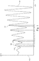
- FIG. 1 shows a schematic representation of the sampling of a received signal, for example an IF signal.
- the horizontal axis 101 represents the course over time and the vertical axis 102 the instantaneous value of the received signal 103.
- the sampling takes place equidistantly at the successive times t0, t1, t2, ..., t17 and supplies the amplitude values 104, 105, 106, ..., 107 corresponding to these times. if two samples were obtained by analog/digital conversion (A/D conversion) and the sampling time and the angular frequency of the carrier oscillation are known.
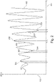
- FIG. 2 shows the schematic representation of another sampling of a received signal, in which the Nyquist-Shannon sampling theorem has been violated.
- the received signal is undersampled.
- the sampling frequency is selected in such a way that no information content is lost in the signal.
- the sampling takes place at different times, with a shorter period of time between the sampling values at the times t0 201 and t1 202, t2 203 and t3 204, t4 205 and t5 206 or t6 207 and t7 208 than between the values at times t1 and t2, t3 and t4, or t5 and t6.
- sampled values at times t0, t2, t4 and t6 can be assigned to a first group of sampled values and the values at times t1, t3, t5 and t7 to a second group.
- FIG. 3 shows the schematic representation of a further sampling of a received signal, for example an IF signal.
- the signal is sampled at times t0, t1, t2, t3 and t4 (and possibly at other times).
- the instantaneous values of the received signal at these points in time are represented by the crosses 301 to 305 on the curve of the received signal 103.
- the frequency of the undersampling is also adapted to the signal characteristics, so that no information content is lost.
- Figure 4A shows the amplitude response, amplitude profile or absolute value of the frequency response A(f) 404 of a so-called phase rotator for an idealized case.
- the horizontal axis 401 represents frequency and the vertical axis 402 represents amplitude.
- the amplitude response has a constant value 404 over the entire frequency axis.
- Figure 4B shows the phase response ⁇ (f) of the phase shifter for this idealized case.
- the horizontal axis 401 represents frequency
- the vertical axis 403 represents phase rotation.
- the signal is rotated by the angle + ⁇ and for frequencies greater than 0 by the angle - ⁇ (see curve sections 405, 406).
- the angle is 0 (see reference number 407 in the coordinate origin).
- the phase rotator rotates the phase, phase position or phase angle in relation to its input data.
- the input data are the converted values of the received signal.
- a further value is calculated from at least one first sample, at which the phase of the underlying IF signal deviates by the specified angle ⁇ from the first sample.
- the calculated value like the sampled value, is an abstract numerical value. Both values differ usually varies in amount depending on the angle of rotation ⁇ . The deviation of the amount in turn results from the underlying IF signal and the angle of rotation.
- an IF signal has been sampled at the maximum of a period.
- the sampled value is A.
- the numerical value A of the sampled value now changes as a function of the angle of rotation ⁇ .
- the new second value is calculated as 0, at an angle of 180° it is calculated as -A, at 270° again as 0 and at 360° as A.
- the function block 801 generates a new value ZF2 i from the digital sampling value ZF1 i , the amount of which corresponds to the underlying harmonic oscillation of the IF signal.
- the rotation of the phase by the angle ⁇ can be translated as a shift by the angle ⁇ of the harmonic oscillation on which the sampled received signal is based.
- the non-time-expanded received signal can also be used instead of an IF signal.
- phase shifter In addition to the term phase rotator, the term phase shifter can also be used.
- the phase shifter can be realized in different ways and can be technically realized by an approximation.
- a suitable approximation, which is carried out for a bandpass signal in the illustrated case, is given in FIGS Figures 5A and 5B shown.
- Figure 5A shows the amplitude response of a real phase shifter and Figure 5B the phase response of a real phase rotator.
- the amplitude and phase response are only relevant in the vicinity of the frequencies -f IF and +f IF (see reference numbers 501, 502 in Figure 5A , 503 and 504 in Figure 5B ). In the other areas, the amplitude and phase response is therefore shown as almost 0 (the amplitude and phase response may also assume other values).
- the filter should of course be implemented according to the bandwidth and carrier frequency of the IF signal. It is therefore useful if f IF corresponds to the center frequency of the IF signal and the bandwidth of the filter is matched to the bandwidth of the signal.
- the phase shifter can be implemented, for example, by a suitable digital filter (FIR or IIR structure).
- FIR digital filter
- IIR structure suitable digital filter
- FIR Finite Impulse Response
- IIR Infinite Impulse Response
- the ideal phase rotator can also be approximated using the Fourier transformation.
- the received signal sampled in the time domain is Fourier transformed and then digitally filtered in the frequency domain.
- the filter operates on the Fourier-transformed input signal by phase rotation, with the components at positive frequencies being rotated by - ⁇ and those at negative frequencies by + ⁇ .
- the phase-shifted signal in the time domain is obtained by the inverse Fourier transformation.
- the received signal (e.g. an IF signal) is sampled and the sampled values are fed to an analog/digital converter 601 . This takes place in the sampling device 702.
- the converted digital values are fed to the phase rotator 602 in step 604.
- the phase rotation or rotation of the phase takes place according to one of the reference to the Figures 5A and 5B described procedure.
- Both the original converted sample values (step 605) and the values calculated by the phase rotator 602 (step 606) are transmitted to the "digital envelope formation" function block 603 .
- the phase rotator and the "digital envelope formation" function block are located in the digital signal processing device 703.
- ⁇ i corresponds to the phase rotation angle (phase value) between the converted IF signal (first group of samples (ZF1)) and the calculated phase-shifted IF signal (second group of samples (ZF2)).
- phase value phase value
- ⁇ i must be specified for a technical implementation.
- the envelope curve or its interpolation points can be calculated using the above formula.
- the sensor 700 shows a level sensor 700 which is attached to a container 704 and is used to determine the level of the filling medium 707 in the container.
- the sensor 700 is designed as a pulse transit time fill level sensor and has a transmitting/receiving antenna 701, which emits a transmission signal 705 to the surface of the filling material.
- the signal 706 reflected on the surface is received by the transceiver unit 701 and the received signal is then sent to the scanning device 702 . If necessary, it is time-expanded before sampling, so that a so-called IF signal is created.
- the (possibly time-expanded) received signal is sampled and the sampled values are converted into digital samples.
- the digitized sample values are then transferred to the digital signal processing device 703, in which the calculation of the envelope values (as described above) takes place.
- the sensor 700 is connected to the outside world via the two-wire loop 708, for example. Both the energy supply and the data exchange take place via the two-wire loop 708 .
- the method according to the invention makes it possible to calculate the envelope with fewer sampled values than in comparable methods.
- the sampling rate of the A/D converter can be reduced.
- the energy consumption by the A/D conversion decreases and it is possible to use A/D converters with lower technical requirements.
- the sampling can (but does not have to) take place at equidistant points in time. This leads to an easier realization of the control of the A/D converter.
Landscapes
- Physics & Mathematics (AREA)
- General Physics & Mathematics (AREA)
- Electromagnetism (AREA)
- Thermal Sciences (AREA)
- Fluid Mechanics (AREA)
- Acoustics & Sound (AREA)
- Engineering & Computer Science (AREA)
- Radar, Positioning & Navigation (AREA)
- Remote Sensing (AREA)
- Radar Systems Or Details Thereof (AREA)
- Measurement Of Velocity Or Position Using Acoustic Or Ultrasonic Waves (AREA)
Claims (15)
- Procédé de calcul d'une amplitude d'enveloppe lors d'une mesure de niveau de remplissage par un capteur de niveau de remplissage, le procédé présentant les étapes consistant à :former un signal de fréquence intermédiaire filtré passe-bande à partir d'un signal de réception du capteur de niveau de remplissage ;échantillonner au moins une partie du signal de fréquence intermédiaire à des instants discrets ;convertir les valeurs d'échantillonnage du signal de fréquence intermédiaire échantillonné en valeurs d'échantillonnage numériques ;calculer une nouvelle valeur pour une première valeur d'échantillonnage numérique des valeurs d'échantillonnage numériques par rotation d'un angle prédéfini de la phase de la valeur d'échantillonnage de la partie échantillonnée du signal de fréquence intermédiaire ;calculer l'amplitude d'enveloppe à partir de la première valeur d'échantillonnage numérique et de la nouvelle valeur calculée par la rotation de la phase.
- Procédé selon la revendication 1,
dans lequel une enveloppe est formée à partir d'une pluralité d'amplitudes d'enveloppe. - Procédé selon la revendication 1, dans lequel la valeur d'enveloppe est calculée selon :
 i : variable courante, i = 0, 1, 2, ...HKi : valeur d'enveloppeZF1i : valeur d'échantillonnage numérique du groupe de valeurs d'échantillonnage numériquesZF2i : nouvelle valeur d'échantillonnage calculée par rotation de la phaseϕi : angle de rotation de phase prédéfini (valeur de phase).
 - Procédé selon l'une des revendications précédentes, dans lequel l'angle prédéfini présente une valeur différente de 90°.
- Procédé selon l'une des revendications précédentes, dans lequel la rotation de phase est effectuée par un filtre numérique dans le domaine temporel.
- Procédé selon la revendication 5, dans lequel le filtre présente une structure de filtre FIR ou IIR.
- Procédé selon l'une des revendications 1 à 4, dans lequel la rotation de phase est effectuée par un filtre numérique dans le domaine fréquentiel.
- Procédé selon la revendication 7, dans lequel le filtre numérique effectue une transformation de Fourier.
- Procédé selon l'une des revendications 1 à 3, dans lequel la rotation de phase est effectuée par un filtre de Hilbert, l'angle prédéfini présentant ainsi une valeur égale à 90°.
- Procédé selon l'une des revendications précédentes, dans lequel on effectue un calcul de moyenne d'ensemble cohérente avant de calculer l'enveloppe.
- Procédé selon l'une des revendications précédentes, dans lequel on calcule une pluralité de valeurs d'enveloppe à partir desquelles on détermine l'enveloppe.
- Capteur de niveau de remplissage (700) pour calculer une amplitude d'enveloppe d'une enveloppe et pour déterminer un niveau de remplissage, le capteur de niveau de remplissage présentant :un dispositif d'échantillonnage (702) pour former un signal de fréquence intermédiaire filtré passe-bande à partir d'un signal de réception du capteur de niveau de remplissage et pour échantillonner au moins une partie d'un signal de fréquence intermédiaire à des instants discrets et convertir les valeurs d'échantillonnage du signal de réception échantillonné en valeurs d'échantillonnage numériques ;un dispositif de traitement de signal numérique (703) pour :calculer une nouvelle valeur pour une première valeur d'échantillonnage numérique des valeurs d'échantillonnage numériques par rotation d'un angle prédéfini de la phase de la valeur d'échantillonnage de la partie échantillonnée du signal de fréquence intermédiaire ;calculer une amplitude d'enveloppe à partir de la première valeur d'échantillonnage numérique et de la nouvelle valeur calculée par la rotation de la phase.
- Agencement d'échantillonnage et de traitement de signal (702, 703) comprenant un dispositif d'échantillonnage (702) et un processeur (703) pour calculer une valeur d'enveloppe d'un signal analogique, exécuté pour mettre en œuvre les étapes selon l'une des revendications 1 à 11.
- Élément de programme qui, lorsqu'il est exécuté sur un agencement d'échantillonnage et de traitement de signal (702, 703), amène l'agencement à mettre en œuvre les étapes selon l'une des revendications 1 à 11.
- Support lisible par ordinateur sur lequel est stocké un élément de programme selon la revendication 14.
Priority Applications (5)
| Application Number | Priority Date | Filing Date | Title |
|---|---|---|---|
| EP12152457.3A EP2620754B1 (fr) | 2012-01-25 | 2012-01-25 | Calcul de courbe d'enveloppe à l'aide d'une rotation de phase |
| HUE12152457A HUE059883T2 (hu) | 2012-01-25 | 2012-01-25 | Burkológörbe számítása fázisforgatással |
| US14/373,594 US20150032411A1 (en) | 2012-01-25 | 2013-01-25 | Envelope Calculation By Means of Phase Rotation |
| PCT/EP2013/051494 WO2013110783A2 (fr) | 2012-01-25 | 2013-01-25 | Calcul de courbe d'enveloppe par rotation de phase |
| CN201380006794.6A CN104583735A (zh) | 2012-01-25 | 2013-01-25 | 借助于相位旋转的包络曲线计算 |
Applications Claiming Priority (1)
| Application Number | Priority Date | Filing Date | Title |
|---|---|---|---|
| EP12152457.3A EP2620754B1 (fr) | 2012-01-25 | 2012-01-25 | Calcul de courbe d'enveloppe à l'aide d'une rotation de phase |
Publications (2)
| Publication Number | Publication Date |
|---|---|
| EP2620754A1 EP2620754A1 (fr) | 2013-07-31 |
| EP2620754B1 true EP2620754B1 (fr) | 2022-06-08 |
Family
ID=45497904
Family Applications (1)
| Application Number | Title | Priority Date | Filing Date |
|---|---|---|---|
| EP12152457.3A Active EP2620754B1 (fr) | 2012-01-25 | 2012-01-25 | Calcul de courbe d'enveloppe à l'aide d'une rotation de phase |
Country Status (5)
| Country | Link |
|---|---|
| US (1) | US20150032411A1 (fr) |
| EP (1) | EP2620754B1 (fr) |
| CN (1) | CN104583735A (fr) |
| HU (1) | HUE059883T2 (fr) |
| WO (1) | WO2013110783A2 (fr) |
Families Citing this family (6)
| Publication number | Priority date | Publication date | Assignee | Title |
|---|---|---|---|---|
| DE102006006572A1 (de) * | 2006-02-13 | 2007-08-16 | Vega Grieshaber Kg | Paarweise ZF-Abtastung für Puls-Laufzeit-Füllstandsensoren |
| DE102015100555A1 (de) | 2015-01-15 | 2016-07-21 | Endress + Hauser Gmbh + Co. Kg | Füllstandmessgerät |
| GB2556563B (en) * | 2015-09-17 | 2021-03-17 | Evoqua Water Tech Llc | Varying water level solids and tracking control |
| CN110160602B (zh) * | 2018-02-11 | 2020-11-24 | 宁波方太厨具有限公司 | 一种吸油烟机的油杯液位测量方法 |
| US10788568B1 (en) * | 2018-07-02 | 2020-09-29 | National Technology & Engineering Solutions Of Sandia, Llc | Instantaneous ultra-wideband sensing using frequency-domain channelization |
| US11776116B1 (en) * | 2019-04-17 | 2023-10-03 | Terrence J. Kepner | System and method of high precision anatomical measurements of features of living organisms including visible contoured shapes |
Citations (2)
| Publication number | Priority date | Publication date | Assignee | Title |
|---|---|---|---|---|
| DE102006006572A1 (de) * | 2006-02-13 | 2007-08-16 | Vega Grieshaber Kg | Paarweise ZF-Abtastung für Puls-Laufzeit-Füllstandsensoren |
| EP2226615A1 (fr) * | 2009-03-02 | 2010-09-08 | VEGA Grieshaber KG | Mesures de niveaux de remplissage à l'aide d'une évaluation d'une courbe d'écho |
Family Cites Families (10)
| Publication number | Priority date | Publication date | Assignee | Title |
|---|---|---|---|---|
| US5303262A (en) * | 1992-02-21 | 1994-04-12 | Hewlett-Packard Company | Method and apparatus for triggering measurements from a TDMA signal |
| JPH07107970B2 (ja) * | 1992-04-10 | 1995-11-15 | 松下電器産業株式会社 | 時間軸反転型直線位相フィルタ |
| US6075408A (en) * | 1998-12-30 | 2000-06-13 | International Business Machines Corp. | OQPSK phase and timing detection |
| US6621763B2 (en) * | 2001-07-23 | 2003-09-16 | Siemens Milltronics Process Instruments Inc. | Power saving technique for pulse-echo acoustic ranging systems |
| US7007052B2 (en) * | 2001-10-30 | 2006-02-28 | Texas Instruments Incorporated | Efficient real-time computation |
| EP1523661B1 (fr) * | 2002-07-19 | 2017-03-01 | VEGA Grieshaber KG | Procede et dispositif permettant de determiner une plage de valeurs escomptees pour un echo de niveau et un echo parasite |
| JP3784823B1 (ja) * | 2005-07-15 | 2006-06-14 | 国立大学法人徳島大学 | 距離測定装置、距離測定方法および距離測定プログラム |
| US7429939B2 (en) * | 2006-09-30 | 2008-09-30 | Teradyne, Inc. | Signal analysis using dual converters and cross spectrum |
| US8581768B1 (en) * | 2011-06-27 | 2013-11-12 | Syntropy Systems, Llc | Linear to discrete quantization conversion with reduced sampling variation errors |
| EP2369362A1 (fr) * | 2010-03-18 | 2011-09-28 | Siemens Milltronics Process Instruments Inc. | Récepteur pour système de télémétrie par impulsion-écho avec filtre numérique à décimation polyphase |
-
2012
- 2012-01-25 EP EP12152457.3A patent/EP2620754B1/fr active Active
- 2012-01-25 HU HUE12152457A patent/HUE059883T2/hu unknown
-
2013
- 2013-01-25 WO PCT/EP2013/051494 patent/WO2013110783A2/fr active Application Filing
- 2013-01-25 US US14/373,594 patent/US20150032411A1/en not_active Abandoned
- 2013-01-25 CN CN201380006794.6A patent/CN104583735A/zh active Pending
Patent Citations (2)
| Publication number | Priority date | Publication date | Assignee | Title |
|---|---|---|---|---|
| DE102006006572A1 (de) * | 2006-02-13 | 2007-08-16 | Vega Grieshaber Kg | Paarweise ZF-Abtastung für Puls-Laufzeit-Füllstandsensoren |
| EP2226615A1 (fr) * | 2009-03-02 | 2010-09-08 | VEGA Grieshaber KG | Mesures de niveaux de remplissage à l'aide d'une évaluation d'une courbe d'écho |
Also Published As
| Publication number | Publication date |
|---|---|
| US20150032411A1 (en) | 2015-01-29 |
| EP2620754A1 (fr) | 2013-07-31 |
| WO2013110783A2 (fr) | 2013-08-01 |
| CN104583735A (zh) | 2015-04-29 |
| HUE059883T2 (hu) | 2023-01-28 |
Similar Documents
| Publication | Publication Date | Title |
|---|---|---|
| EP1984707B1 (fr) | Balayage de fréquences moyennes par paires destiné à des détecteurs de niveau par durée de propagation d'impulsions | |
| DE4407369C2 (de) | Verfahren und Schaltungsanordnung zur Laufzeitmessung sowie deren Verwendung | |
| EP2620754B1 (fr) | Calcul de courbe d'enveloppe à l'aide d'une rotation de phase | |
| DE69730416T2 (de) | Füllstandmessradargerät | |
| EP2997336B1 (fr) | Mesure de niveau à détermination améliorée de l'éloignement | |
| EP2226615B1 (fr) | Mesures de niveaux de remplissage à l'aide d'une évaluation d'une courbe d'écho | |
| EP2128576B1 (fr) | Procédé de détection de double parole basé sur les propriétés acoustiques spectrales | |
| DE102008050117A1 (de) | Kalibration einer Radareinheit mit gerätespezifischen Korrekturkurven | |
| WO2015018586A1 (fr) | Correction de la dispersion de radar fmcw dans un tube | |
| DE102014101904A1 (de) | Effiziente Dispersionskorrektur für FMCW-Radar in einem Rohr | |
| DE3038961A1 (de) | Einrichtung zur bestimmung von daten eines signalausbreitungsweges, insbesondere nach dem rueckstrahlprinzip arbeitendes messsystem | |
| DE102006058852A1 (de) | Verfahren und Vorrichtung zur Korrektur nichtidealer Zwischenfrequenzsignale bei Abstandsmessgeräten nach dem FMCW-Prinzip | |
| DE102005021358A1 (de) | Laufzeitmessverfahren zur Ermittelung der Distanz | |
| WO2011076478A2 (fr) | Procédé de détermination et de surveillance du niveau de remplissage d'un contenant, renfermant un fluide, selon un procédé de mesure du temps de propagation | |
| DE102007042042A1 (de) | Verfahren zur Ermittlung und Überwachung des Füllstands eines Mediums in einem Behälter nach einem Laufzeitmessverfahren | |
| EP2626676B1 (fr) | Dispositif et procédé de correction d'un décalage | |
| DE102012107146A1 (de) | Verfahren zur Bestimmung und/oder Überwachung des Füllstands eines Mediums in einem Behälter | |
| EP1210567A1 (fr) | Dispositif permettant de determiner une grandeur physique relative a un milieu | |
| DE102005033403A1 (de) | Verfahren und Schaltungsanordnung zur genauen Entfernungsbestimmung | |
| EP2327966B1 (fr) | Mesure de distance d'une surface de séparation | |
| WO2020157039A2 (fr) | Dispositif pour traiter un signal d'un système de localisation ainsi que procédé de simulation et de localisation d'un objet | |
| EP3467451A1 (fr) | Procédé et appareil de mesure de niveau de remplissage permettant de déterminer le niveau de remplissage d'un milieu au moyen d'une mesure radar continue | |
| EP0389670A2 (fr) | Appareil de mesure de la vitesse propre d'un véhicule selon le principe d'un radar Doppler. | |
| EP2789996B1 (fr) | Détermination de courbe d'échos avec résolution différente selon la zone | |
| EP1004036B1 (fr) | Procede et dispositif de mesure de distance et de vitesse |
Legal Events
| Date | Code | Title | Description |
|---|---|---|---|
| PUAI | Public reference made under article 153(3) epc to a published international application that has entered the european phase |
Free format text: ORIGINAL CODE: 0009012 |
|
| AK | Designated contracting states |
Kind code of ref document: A1 Designated state(s): AL AT BE BG CH CY CZ DE DK EE ES FI FR GB GR HR HU IE IS IT LI LT LU LV MC MK MT NL NO PL PT RO RS SE SI SK SM TR |
|
| AX | Request for extension of the european patent |
Extension state: BA ME |
|
| 17P | Request for examination filed |
Effective date: 20131211 |
|
| RBV | Designated contracting states (corrected) |
Designated state(s): AL AT BE BG CH CY CZ DE DK EE ES FI FR GB GR HR HU IE IS IT LI LT LU LV MC MK MT NL NO PL PT RO RS SE SI SK SM TR |
|
| STAA | Information on the status of an ep patent application or granted ep patent |
Free format text: STATUS: EXAMINATION IS IN PROGRESS |
|
| 17Q | First examination report despatched |
Effective date: 20180919 |
|
| STAA | Information on the status of an ep patent application or granted ep patent |
Free format text: STATUS: EXAMINATION IS IN PROGRESS |
|
| APBK | Appeal reference recorded |
Free format text: ORIGINAL CODE: EPIDOSNREFNE |
|
| APBN | Date of receipt of notice of appeal recorded |
Free format text: ORIGINAL CODE: EPIDOSNNOA2E |
|
| APBR | Date of receipt of statement of grounds of appeal recorded |
Free format text: ORIGINAL CODE: EPIDOSNNOA3E |
|
| APAF | Appeal reference modified |
Free format text: ORIGINAL CODE: EPIDOSCREFNE |
|
| APBT | Appeal procedure closed |
Free format text: ORIGINAL CODE: EPIDOSNNOA9E |
|
| STAA | Information on the status of an ep patent application or granted ep patent |
Free format text: STATUS: EXAMINATION IS IN PROGRESS |
|
| GRAP | Despatch of communication of intention to grant a patent |
Free format text: ORIGINAL CODE: EPIDOSNIGR1 |
|
| STAA | Information on the status of an ep patent application or granted ep patent |
Free format text: STATUS: GRANT OF PATENT IS INTENDED |
|
| INTG | Intention to grant announced |
Effective date: 20220118 |
|
| RIN1 | Information on inventor provided before grant (corrected) |
Inventor name: HOFERER, CHRISTIAN Inventor name: REICH, WERNER Inventor name: WELLE, ROLAND |
|
| GRAS | Grant fee paid |
Free format text: ORIGINAL CODE: EPIDOSNIGR3 |
|
| GRAA | (expected) grant |
Free format text: ORIGINAL CODE: 0009210 |
|
| STAA | Information on the status of an ep patent application or granted ep patent |
Free format text: STATUS: THE PATENT HAS BEEN GRANTED |
|
| RIN1 | Information on inventor provided before grant (corrected) |
Inventor name: HOFERER, CHRISTIAN Inventor name: REICH, WERNER Inventor name: WELLE, ROLAND |
|
| AK | Designated contracting states |
Kind code of ref document: B1 Designated state(s): AL AT BE BG CH CY CZ DE DK EE ES FI FR GB GR HR HU IE IS IT LI LT LU LV MC MK MT NL NO PL PT RO RS SE SI SK SM TR |
|
| REG | Reference to a national code |
Ref country code: GB Ref legal event code: FG4D Free format text: NOT ENGLISH |
|
| REG | Reference to a national code |
Ref country code: AT Ref legal event code: REF Ref document number: 1497238 Country of ref document: AT Kind code of ref document: T Effective date: 20220615 Ref country code: CH Ref legal event code: EP |
|
| REG | Reference to a national code |
Ref country code: DE Ref legal event code: R096 Ref document number: 502012017055 Country of ref document: DE |
|
| REG | Reference to a national code |
Ref country code: IE Ref legal event code: FG4D Free format text: LANGUAGE OF EP DOCUMENT: GERMAN |
|
| REG | Reference to a national code |
Ref country code: LT Ref legal event code: MG9D |
|
| REG | Reference to a national code |
Ref country code: NL Ref legal event code: MP Effective date: 20220608 |
|
| PG25 | Lapsed in a contracting state [announced via postgrant information from national office to epo] |
Ref country code: SE Free format text: LAPSE BECAUSE OF FAILURE TO SUBMIT A TRANSLATION OF THE DESCRIPTION OR TO PAY THE FEE WITHIN THE PRESCRIBED TIME-LIMIT Effective date: 20220608 Ref country code: NO Free format text: LAPSE BECAUSE OF FAILURE TO SUBMIT A TRANSLATION OF THE DESCRIPTION OR TO PAY THE FEE WITHIN THE PRESCRIBED TIME-LIMIT Effective date: 20220908 Ref country code: LT Free format text: LAPSE BECAUSE OF FAILURE TO SUBMIT A TRANSLATION OF THE DESCRIPTION OR TO PAY THE FEE WITHIN THE PRESCRIBED TIME-LIMIT Effective date: 20220608 Ref country code: HR Free format text: LAPSE BECAUSE OF FAILURE TO SUBMIT A TRANSLATION OF THE DESCRIPTION OR TO PAY THE FEE WITHIN THE PRESCRIBED TIME-LIMIT Effective date: 20220608 Ref country code: GR Free format text: LAPSE BECAUSE OF FAILURE TO SUBMIT A TRANSLATION OF THE DESCRIPTION OR TO PAY THE FEE WITHIN THE PRESCRIBED TIME-LIMIT Effective date: 20220909 Ref country code: FI Free format text: LAPSE BECAUSE OF FAILURE TO SUBMIT A TRANSLATION OF THE DESCRIPTION OR TO PAY THE FEE WITHIN THE PRESCRIBED TIME-LIMIT Effective date: 20220608 Ref country code: ES Free format text: LAPSE BECAUSE OF FAILURE TO SUBMIT A TRANSLATION OF THE DESCRIPTION OR TO PAY THE FEE WITHIN THE PRESCRIBED TIME-LIMIT Effective date: 20220608 Ref country code: BG Free format text: LAPSE BECAUSE OF FAILURE TO SUBMIT A TRANSLATION OF THE DESCRIPTION OR TO PAY THE FEE WITHIN THE PRESCRIBED TIME-LIMIT Effective date: 20220908 |
|
| PG25 | Lapsed in a contracting state [announced via postgrant information from national office to epo] |
Ref country code: RS Free format text: LAPSE BECAUSE OF FAILURE TO SUBMIT A TRANSLATION OF THE DESCRIPTION OR TO PAY THE FEE WITHIN THE PRESCRIBED TIME-LIMIT Effective date: 20220608 Ref country code: LV Free format text: LAPSE BECAUSE OF FAILURE TO SUBMIT A TRANSLATION OF THE DESCRIPTION OR TO PAY THE FEE WITHIN THE PRESCRIBED TIME-LIMIT Effective date: 20220608 |
|
| PG25 | Lapsed in a contracting state [announced via postgrant information from national office to epo] |
Ref country code: NL Free format text: LAPSE BECAUSE OF FAILURE TO SUBMIT A TRANSLATION OF THE DESCRIPTION OR TO PAY THE FEE WITHIN THE PRESCRIBED TIME-LIMIT Effective date: 20220608 |
|
| REG | Reference to a national code |
Ref country code: HU Ref legal event code: AG4A Ref document number: E059883 Country of ref document: HU |
|
| PG25 | Lapsed in a contracting state [announced via postgrant information from national office to epo] |
Ref country code: SM Free format text: LAPSE BECAUSE OF FAILURE TO SUBMIT A TRANSLATION OF THE DESCRIPTION OR TO PAY THE FEE WITHIN THE PRESCRIBED TIME-LIMIT Effective date: 20220608 Ref country code: SK Free format text: LAPSE BECAUSE OF FAILURE TO SUBMIT A TRANSLATION OF THE DESCRIPTION OR TO PAY THE FEE WITHIN THE PRESCRIBED TIME-LIMIT Effective date: 20220608 Ref country code: RO Free format text: LAPSE BECAUSE OF FAILURE TO SUBMIT A TRANSLATION OF THE DESCRIPTION OR TO PAY THE FEE WITHIN THE PRESCRIBED TIME-LIMIT Effective date: 20220608 Ref country code: PT Free format text: LAPSE BECAUSE OF FAILURE TO SUBMIT A TRANSLATION OF THE DESCRIPTION OR TO PAY THE FEE WITHIN THE PRESCRIBED TIME-LIMIT Effective date: 20221010 Ref country code: EE Free format text: LAPSE BECAUSE OF FAILURE TO SUBMIT A TRANSLATION OF THE DESCRIPTION OR TO PAY THE FEE WITHIN THE PRESCRIBED TIME-LIMIT Effective date: 20220608 Ref country code: CZ Free format text: LAPSE BECAUSE OF FAILURE TO SUBMIT A TRANSLATION OF THE DESCRIPTION OR TO PAY THE FEE WITHIN THE PRESCRIBED TIME-LIMIT Effective date: 20220608 |
|
| PG25 | Lapsed in a contracting state [announced via postgrant information from national office to epo] |
Ref country code: PL Free format text: LAPSE BECAUSE OF FAILURE TO SUBMIT A TRANSLATION OF THE DESCRIPTION OR TO PAY THE FEE WITHIN THE PRESCRIBED TIME-LIMIT Effective date: 20220608 Ref country code: IS Free format text: LAPSE BECAUSE OF FAILURE TO SUBMIT A TRANSLATION OF THE DESCRIPTION OR TO PAY THE FEE WITHIN THE PRESCRIBED TIME-LIMIT Effective date: 20221008 |
|
| REG | Reference to a national code |
Ref country code: DE Ref legal event code: R097 Ref document number: 502012017055 Country of ref document: DE |
|
| PG25 | Lapsed in a contracting state [announced via postgrant information from national office to epo] |
Ref country code: AL Free format text: LAPSE BECAUSE OF FAILURE TO SUBMIT A TRANSLATION OF THE DESCRIPTION OR TO PAY THE FEE WITHIN THE PRESCRIBED TIME-LIMIT Effective date: 20220608 |
|
| PLBE | No opposition filed within time limit |
Free format text: ORIGINAL CODE: 0009261 |
|
| STAA | Information on the status of an ep patent application or granted ep patent |
Free format text: STATUS: NO OPPOSITION FILED WITHIN TIME LIMIT |
|
| PG25 | Lapsed in a contracting state [announced via postgrant information from national office to epo] |
Ref country code: DK Free format text: LAPSE BECAUSE OF FAILURE TO SUBMIT A TRANSLATION OF THE DESCRIPTION OR TO PAY THE FEE WITHIN THE PRESCRIBED TIME-LIMIT Effective date: 20220608 |
|
| 26N | No opposition filed |
Effective date: 20230310 |
|
| PG25 | Lapsed in a contracting state [announced via postgrant information from national office to epo] |
Ref country code: SI Free format text: LAPSE BECAUSE OF FAILURE TO SUBMIT A TRANSLATION OF THE DESCRIPTION OR TO PAY THE FEE WITHIN THE PRESCRIBED TIME-LIMIT Effective date: 20220608 |
|
| P01 | Opt-out of the competence of the unified patent court (upc) registered |
Effective date: 20230525 |
|
| REG | Reference to a national code |
Ref country code: CH Ref legal event code: PL |
|
| GBPC | Gb: european patent ceased through non-payment of renewal fee |
Effective date: 20230125 |
|
| PG25 | Lapsed in a contracting state [announced via postgrant information from national office to epo] |
Ref country code: LU Free format text: LAPSE BECAUSE OF NON-PAYMENT OF DUE FEES Effective date: 20230125 |
|
| REG | Reference to a national code |
Ref country code: BE Ref legal event code: MM Effective date: 20230131 |
|
| PG25 | Lapsed in a contracting state [announced via postgrant information from national office to epo] |
Ref country code: LI Free format text: LAPSE BECAUSE OF NON-PAYMENT OF DUE FEES Effective date: 20230131 Ref country code: GB Free format text: LAPSE BECAUSE OF NON-PAYMENT OF DUE FEES Effective date: 20230125 Ref country code: CH Free format text: LAPSE BECAUSE OF NON-PAYMENT OF DUE FEES Effective date: 20230131 |
|
| PG25 | Lapsed in a contracting state [announced via postgrant information from national office to epo] |
Ref country code: FR Free format text: LAPSE BECAUSE OF NON-PAYMENT OF DUE FEES Effective date: 20230131 Ref country code: BE Free format text: LAPSE BECAUSE OF NON-PAYMENT OF DUE FEES Effective date: 20230131 |
|
| PG25 | Lapsed in a contracting state [announced via postgrant information from national office to epo] |
Ref country code: IT Free format text: LAPSE BECAUSE OF FAILURE TO SUBMIT A TRANSLATION OF THE DESCRIPTION OR TO PAY THE FEE WITHIN THE PRESCRIBED TIME-LIMIT Effective date: 20220608 Ref country code: IE Free format text: LAPSE BECAUSE OF NON-PAYMENT OF DUE FEES Effective date: 20230125 |
|
| REG | Reference to a national code |
Ref country code: AT Ref legal event code: MM01 Ref document number: 1497238 Country of ref document: AT Kind code of ref document: T Effective date: 20230125 |
|
| PG25 | Lapsed in a contracting state [announced via postgrant information from national office to epo] |
Ref country code: AT Free format text: LAPSE BECAUSE OF NON-PAYMENT OF DUE FEES Effective date: 20230125 |
|
| PG25 | Lapsed in a contracting state [announced via postgrant information from national office to epo] |
Ref country code: AT Free format text: LAPSE BECAUSE OF NON-PAYMENT OF DUE FEES Effective date: 20230125 |
|
| PGFP | Annual fee paid to national office [announced via postgrant information from national office to epo] |
Ref country code: HU Payment date: 20240124 Year of fee payment: 13 Ref country code: DE Payment date: 20240119 Year of fee payment: 13 |
|
| PG25 | Lapsed in a contracting state [announced via postgrant information from national office to epo] |
Ref country code: MC Free format text: LAPSE BECAUSE OF FAILURE TO SUBMIT A TRANSLATION OF THE DESCRIPTION OR TO PAY THE FEE WITHIN THE PRESCRIBED TIME-LIMIT Effective date: 20220608 |
|
| PG25 | Lapsed in a contracting state [announced via postgrant information from national office to epo] |
Ref country code: MC Free format text: LAPSE BECAUSE OF FAILURE TO SUBMIT A TRANSLATION OF THE DESCRIPTION OR TO PAY THE FEE WITHIN THE PRESCRIBED TIME-LIMIT Effective date: 20220608 |