EP2620735A1 - Support de tube d'échange et ensemble de fixation pour échangeur de tube - Google Patents
Support de tube d'échange et ensemble de fixation pour échangeur de tube Download PDFInfo
- Publication number
- EP2620735A1 EP2620735A1 EP13152013.2A EP13152013A EP2620735A1 EP 2620735 A1 EP2620735 A1 EP 2620735A1 EP 13152013 A EP13152013 A EP 13152013A EP 2620735 A1 EP2620735 A1 EP 2620735A1
- Authority
- EP
- European Patent Office
- Prior art keywords
- rods
- support
- ring
- another
- supports
- Prior art date
- Legal status (The legal status is an assumption and is not a legal conclusion. Google has not performed a legal analysis and makes no representation as to the accuracy of the status listed.)
- Granted
Links
- 238000005520 cutting process Methods 0.000 claims abstract description 19
- 238000005452 bending Methods 0.000 claims description 9
- 230000001747 exhibiting effect Effects 0.000 claims description 3
- 238000000227 grinding Methods 0.000 claims description 3
- 238000003801 milling Methods 0.000 claims description 3
- 238000003466 welding Methods 0.000 claims description 2
- 239000012530 fluid Substances 0.000 abstract description 30
- 238000004519 manufacturing process Methods 0.000 description 9
- 230000006978 adaptation Effects 0.000 description 2
- 238000009434 installation Methods 0.000 description 2
- 239000007788 liquid Substances 0.000 description 2
- 238000003754 machining Methods 0.000 description 2
- 239000000463 material Substances 0.000 description 2
- 238000011084 recovery Methods 0.000 description 2
- 230000035939 shock Effects 0.000 description 2
- OKTJSMMVPCPJKN-UHFFFAOYSA-N Carbon Chemical compound [C] OKTJSMMVPCPJKN-UHFFFAOYSA-N 0.000 description 1
- 229910000831 Steel Inorganic materials 0.000 description 1
- 229910052799 carbon Inorganic materials 0.000 description 1
- 238000001816 cooling Methods 0.000 description 1
- 238000013016 damping Methods 0.000 description 1
- 238000005553 drilling Methods 0.000 description 1
- 238000010438 heat treatment Methods 0.000 description 1
- 238000003780 insertion Methods 0.000 description 1
- 230000037431 insertion Effects 0.000 description 1
- 239000002184 metal Substances 0.000 description 1
- 230000008520 organization Effects 0.000 description 1
- 229910001220 stainless steel Inorganic materials 0.000 description 1
- 239000010935 stainless steel Substances 0.000 description 1
- 239000010959 steel Substances 0.000 description 1
- XLYOFNOQVPJJNP-UHFFFAOYSA-N water Substances O XLYOFNOQVPJJNP-UHFFFAOYSA-N 0.000 description 1
Images


Classifications
-
- F—MECHANICAL ENGINEERING; LIGHTING; HEATING; WEAPONS; BLASTING
- F28—HEAT EXCHANGE IN GENERAL
- F28F—DETAILS OF HEAT-EXCHANGE AND HEAT-TRANSFER APPARATUS, OF GENERAL APPLICATION
- F28F9/00—Casings; Header boxes; Auxiliary supports for elements; Auxiliary members within casings
- F28F9/007—Auxiliary supports for elements
- F28F9/013—Auxiliary supports for elements for tubes or tube-assemblies
- F28F9/0132—Auxiliary supports for elements for tubes or tube-assemblies formed by slats, tie-rods, articulated or expandable rods
-
- F—MECHANICAL ENGINEERING; LIGHTING; HEATING; WEAPONS; BLASTING
- F28—HEAT EXCHANGE IN GENERAL
- F28F—DETAILS OF HEAT-EXCHANGE AND HEAT-TRANSFER APPARATUS, OF GENERAL APPLICATION
- F28F9/00—Casings; Header boxes; Auxiliary supports for elements; Auxiliary members within casings
- F28F9/007—Auxiliary supports for elements
- F28F9/013—Auxiliary supports for elements for tubes or tube-assemblies
- F28F9/0135—Auxiliary supports for elements for tubes or tube-assemblies formed by grids having only one tube per closed grid opening
- F28F9/0136—Auxiliary supports for elements for tubes or tube-assemblies formed by grids having only one tube per closed grid opening formed by intersecting strips
-
- F—MECHANICAL ENGINEERING; LIGHTING; HEATING; WEAPONS; BLASTING
- F28—HEAT EXCHANGE IN GENERAL
- F28D—HEAT-EXCHANGE APPARATUS, NOT PROVIDED FOR IN ANOTHER SUBCLASS, IN WHICH THE HEAT-EXCHANGE MEDIA DO NOT COME INTO DIRECT CONTACT
- F28D7/00—Heat-exchange apparatus having stationary tubular conduit assemblies for both heat-exchange media, the media being in contact with different sides of a conduit wall
- F28D7/08—Heat-exchange apparatus having stationary tubular conduit assemblies for both heat-exchange media, the media being in contact with different sides of a conduit wall the conduits being otherwise bent, e.g. in a serpentine or zig-zag
-
- F—MECHANICAL ENGINEERING; LIGHTING; HEATING; WEAPONS; BLASTING
- F28—HEAT EXCHANGE IN GENERAL
- F28D—HEAT-EXCHANGE APPARATUS, NOT PROVIDED FOR IN ANOTHER SUBCLASS, IN WHICH THE HEAT-EXCHANGE MEDIA DO NOT COME INTO DIRECT CONTACT
- F28D7/00—Heat-exchange apparatus having stationary tubular conduit assemblies for both heat-exchange media, the media being in contact with different sides of a conduit wall
- F28D7/16—Heat-exchange apparatus having stationary tubular conduit assemblies for both heat-exchange media, the media being in contact with different sides of a conduit wall the conduits being arranged in parallel spaced relation
Definitions
- the present invention relates to the field of the heat exchangers that are used to exchange heat energy from one fluid to another without mixing them.
- the invention relates more particularly to the large size exchangers of tube type comprising supports making it possible to support a tube bundle intended to convey a fluid.
- the field of the invention relates more specifically to that of the supports, such as rings, comprising elements making it possible to secure tubes of the tube exchangers.
- the tube exchangers are particularly appreciated for their resistance to high pressures, the adaptation to different powers and to wide temperature deviations. They offer the advantage of being economical and compact. They are used most often for heat transfers between two volumes of water or more generally between a volume of liquid or of gas and another volume of liquid or of gas.
- Some tube exchangers comprise supports which make it possible to limit the head losses of the fluids circulating in a calender and can also make it possible to better withstand the mechanical stresses due to the vibrations of the structure, these vibrations being mainly due to the arrival of the fluid in the calender which strikes the bundle, generally at right angles.
- FIG. 1 An exemplary exchanger is represented in figure 1 , similar to that which is described in the patent US2009/0200004 , in which circular baffle plates 8 also make it possible to secure the exchange tubes 9 along the exchanger by the presence of a plurality of holes allowing for the passage of the tubes 9.
- the plates 6, 7 are spaced apart in a calender 10 forming the shell of the exchanger 1 so as to secure, at the ends of the calender, the exchange tubes 9 all along the exchanger 1.
- the tubes 9 are parallel and pass through the volume of the calender.
- the baffle plates make it possible to circulate a fluid along a route 11 in the exchanger 1 from an inlet nozzle 4 to an outlet nozzle 5.
- An inlet 2 makes it possible to circulate a first fluid in the exchange tubes 9.
- the first fluid leaves through an outlet 3 at the other end of the exchanger 1.
- An inlet 4 makes it possible to circulate a second fluid in the calender.
- the second fluid leaves the exchanger through an outlet 5 at the other end of the exchanger 1.
- the two fluids exchange heat by contact between the second fluid and the exchange tubes.
- FIG. 2 represents another exemplary exchanger 20 of the prior art.
- the exchanger type is tubular.
- Rings 25 are spaced apart in a calender 21 forming the shell of the exchanger 20 so as to secure the tubes all along the exchanger 20.
- Nozzles 22, 24 make it possible to inject or recover a fluid circulating in the calender.
- a grid forms the interior of each ring making it possible to support a portion of the effort used to secure the tubes and to minimize the lateral movements of the exchange tubes.
- the term "interior” should be understood to mean the space delimited by the dimensions of the ring, or its diameter and its thickness.
- the grid allows for an easy passage of fluid in the calender because, on each ring, there is only one row of tubes in every two which is secured with the rods. This leaves many sections of passage for the fluid, which makes it possible to have low head losses.
- Figure 2 represents a support plate 23 securing the tubes in a holed plate. The rings then positioned allow for a recovery of effort to maintain a stable position for the tubes while making it possible to absorb vibrations.
- tubular exchanger with straight tubes there are two support plates which secure the tubes in a holed plate at the ends.
- the rings positioned between the two plates allow for a recovery of effort to maintain a stable position for the tubes while making it possible to absorb vibrations.
- rings very close together are required; at least four rings, or three intervals, are required to secure a tube in all the directions at right angles to its axis.
- Figure 2 represents an embodiment of this design in which the rings are spaced apart by 158.5 mm from one another. Consequently, the number of rings per apparatus is significant.
- devices according to the prior art generally incur a significant manufacturing cost due to the fitting of numerous rings to secure the exchange tubes and lead to head losses in the guiding of the fluid in the calender.
- the support of the invention makes it possible to overcome all or part of the abovementioned drawbacks.
- the support of the invention makes it possible to reduce the head losses of the fluids as they are being guided in the calender, to reduce the weight of an exchanger and to augment the securing of the exchange tubes.
- a support for an exchange tube bundle forming, in a cutting plane, a mesh
- said support comprising a ring
- the ring comprises fastening means making it possible to fasten, respectively, on either side of the cutting plane of the ring, a first set of rods and a second set of rods, said rods each having a form which constitutes a median plane, the median planes of the first set being parallel to one another and the median planes of the second set being parallel to one another, the orientation of the median planes of the first set and of the median planes of the second set forming a first angle greater than zero.
- Such a device makes it possible to address all or part of the drawbacks of the prior art, notably because it allows for an exchanger design having at least two times fewer rings. This also makes it possible to reduce the head losses inside such an exchanger provided with such supports.
- the form of the rods is a "U" form, that is to say a form having a central segment and two lateral segments forming the "U".
- the first angle and the number of rods of each set are chosen so as to form a frame exhibiting patterns corresponding to the mesh of the bundle.
- Such a support makes it possible to improve the securing of the exchange tubes while absorbing any vibrations. Such a support also makes it possible to increase the stability of the exchanger and reduce the weight thereof.
- the first angle is substantially equal to 90° or substantially equal to 60°.
- the section of the ring is square and/or its lateral faces are substantially planar. This notably allows for easy adaptation of the rods on either side of the ring.
- the rods are fastened to the ring by shrink-fitting into holes preformed on each of the lateral faces of the ring thus forming the fastening means.
- the shrink-fitting of the rods can be complemented by a step of welding on each of the lateral faces of the ring.
- the rods can be welded without necessarily being shrink-fitted.
- the weld forms the fastening means.
- the rods are:
- the lateral segments are preferably machined, either by turning before bending, or by grinding or milling before or after bending. It should be noted that, in the general case, whatever the structure of the rod, the latter can be machined. For example, a rod of single-piece structure formed by bending can be machined on these lateral segments. This is particularly advantageous to reduce their thicknesses (or their diameter) in order to adapt their flexibility if necessary, the machining of the rods taking place before their bending.
- Such features relating to the rods notably make it possible to be able to design said rods in such a way that they exhibit a flexibility suited to best damping the vibrations but above all to reduce the play of the tubes in relation to the mesh to zero to have a firm contact.
- the central section of the rods is more rigid than the lateral sections of said rods. This makes it possible notably to guarantee that the flexibility seen by the tubes at the center of the bundle is the same as the flexibility seen by the tubes on the edges of the bundle.
- the invention also relates to a securing assembly comprising at least two supports as described, the supports are spaced apart by a first distance and oriented relative to one another by the first angle.
- the supports of the securing assembly are mounted in series. This makes it possible notably to have an optimal rod mesh in order to arrange the exchange tubes therein.
- the invention also relates to a heat exchanger comprising a calender which encloses at least one bundle of exchange tubes and at least three exchange tube bundle supports forming, in a cutting plane, a mesh, said support comprising a ring, wherein the ring comprises fastening means making it possible to fasten, respectively, on either side of the cutting plane of the ring, a first set of rods and a second set of rods, said rods each forming a "U", each constituting a median plane, the median planes of the first set being parallel to one another and the median planes of the second set being parallel to one another, the orientation of the median planes of the first set and of the median planes of the second set forming a first angle greater than zero.
- Such an exchanger makes it possible to address all or part of the drawbacks of the prior art notably because it requires at least two times fewer rings than what is proposed by the prior art. This also makes it possible to reduce the head losses inside such an exchanger provided with such supports.
- ring should be understood to mean an element having a closed contour having a certain thickness and delimiting an interior space that is open on either side of the closed contour.
- the closed contour has a substantially circular profile but it may have a different profile, for example oval, oblong, etc.
- calender should be understood to mean the shell of the exchanger into which a fluid is injected for its cooling or its heating and which comprises rings such as those defined in the present invention. Generally, a calender is cylindrical.
- exchanger of calender tube type should be understood to mean an exchanger in which at least two fluids exchange heat, one fluid circulating in the calender and a second fluid circulating in the tubes.
- the surface of the tubes serving as support for the heat exchange between the two fluids.
- rod in "U” form should be understood to mean a rod assembled or folded or bent which forms three branches, each branch having a join with another branch forming an angle less than 180°.
- Figures 3A, 3B, 3C and 3D represent examples of rods which can be used in the support of the invention.
- baffle plate should be understood, notably for a good understanding of the prior art, to mean a device making it possible to modify the direction of a fluid. In the field of heat exchangers, the term “baffle” is often used. The prior art discloses baffle plates that are used also to secure the tubes.
- a support for exchange tubes of the invention makes it possible to reduce the number of rings of an exchanger while making it possible to offer enhanced flexibility in the installation of an exchanger. Furthermore, the support of the invention makes it possible to improve the securing of the exchange tubes while absorbing any vibrations. The support of the invention makes it possible to increase the stability of the exchanger and reduce the weight thereof.
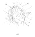
- Figure 4 represents a support 400 of the invention, suitable for a so-called "calender tube” exchanger of circular form, comprising a ring 40 having a circular profile, a first set 41 of rods 410 and a second set 42 of rods 420.
- the rods 410, 420 of the two sets 41, 42 are fastened to the ring 40 on either side on the flanges of the ring 40 which respectively represent first and second lateral surfaces 401, 402 of the ring 40 delimiting a thickness of the ring.
- the ring 40 can have a parallelepipedal section such as a rectangle or a square or can even have a circular section.
- a preferred embodiment is based on a ring 40 with square section on which the first and second lateral surfaces 401, 402 of the ring 40 are substantially coplanar and spaced apart from one another by a distance equal to the thickness of the ring 40.
- each rod 410, 420 having a form which constitutes a median plane, the form of the rods here being substantially a "U" form.
- the "U” form can be obtained by bending, folding or by assembling three rod branches. Moreover, the "U” form can be described as comprising a central segment provided with two ends and two lateral segments provided with two ends, each of the lateral segments being attached by one of their ends to an end of the lateral segment.
- the first set 41 of rods 410 has a plurality of rods 410 parallel with one another, each rod 410 forming a "U" of which each end is fastened to the first lateral face 401 of the ring 40, the ends of the rods in "U” form corresponding to two ends of the lateral segments.
- the second set 42 of rods 420 has the same properties as the first, except that the rods 420 are fastened to the second lateral face 402 of the ring 30. Furthermore, the median planes of the first set 41 are parallel with one another and the median planes of the second set 42 are parallel with one another, the orientation of the median planes of the first set 41 and of the median planes of the second set 42 forming a first angle ⁇ greater than zero.
- first and second sets 41, 42 of rods 410, 420 are oriented relative to one another by a first angle equal to 90° in the example of figure 4 .
- the axis (O, x) corresponds to the axis according to which the tubes of the exchange tube bundle will be positioned so that they are colinear to said axis (O, x).
- (O, y, z) be a cutting plane normal to the axis (O, x) having for origin the center of the ring so that the ring is substantially coaxial to the axis (O, x), the coordinate system (O, x, y, z) also forming an orthogonal trihedron.
- (O', y', z') be a first orthogonal coordinate system defining a first plane normal to the axis (O, x) comprising substantially the central segments of each rod 410 of the first set 41 of rods 410, said first plane being at a distance from the cutting plane by a length equal to the length of the segment [O, O'], O' having the coordinates (x1, 0, 0) in the coordinate system (O, x, y, z).
- the median planes of the first set 41 are parallel with one another, parallel to the plane (O', x, z') and orthogonal to the cutting plane (O, y, z).
- (O", y" , z") be a second orthogonal coordinate system defining a second plane normal to the axis (O, x) comprising substantially the central segments of each rod 420 of the second set 42 of rods 420, said first plane being at a distance from the cutting plane by a length equal to the length of the segment [O", O], O" having the coordinates (x2, 0, 0) in the coordinate system (O, x, y, z).
- the median planes of the second set 42 are parallel with one another, parallel to the plane (O", x, y") and orthogonal to the cutting plane (O, y, z).
- first and second planes are then at a distance from one another by a distance [O', O"] equal to the sum of the thickness of the ring 40 and of the lengths of the lateral segments of the rods 410 of the first set 41 and of the rods 420 of the second set 42.
- a distance [O', O"] equal to the sum of the thickness of the ring 40 and of the lengths of the lateral segments of the rods 410 of the first set 41 and of the rods 420 of the second set 42.
- Each of the first and second planes being normal to the axis (O, x), the length of the rods 410 of the first set 41 are equal to one another, as is the length of the rods 420 of the second set 42.
- Such an orientation of the first and second sets relative to one another by a first angle equal to 90° makes it possible to immobilize the exchange tubes in at least one direction of each axis colinear to the axes (O, y) and (O, z) of the plane (O, y, z) respectively in the first plane and in the second plane.
- the orientation as illustrated makes it possible to immobilize the exchange tubes at least on the axis (O', y') and the axis (O", z").
- each rod 410 has an abscissa on the axis (O', y'). If we consider two successive rods of the first set 41, their abscissae being denoted y'1 and y'2.
- the second set 42 of rods 420 they are positioned horizontally since they form an angle of 90° with the rods 420 of the first set 42, i.e. according to an axis colinear to the axis (O, y). Each rod 420 has an ordinate on the axis (O", z") . If we consider two successive rods of the second set 42, their ordinates are denoted respectively z"1 and z"2.
- the rods form a frame in which the two successive rods of the first set 41 have abscissae denoted y1 and y2 and in which the two successive rods of the second set 42 have ordinates denoted respectively z1 and z2.
- An exchange tube is modeled in this example by a substantially cylindrical structure having an axis of revolution colinear to the axis (O, x).
- Such a tube passing between two parallel rods of the first set 41 and two parallel rods of the second set 42 would be contained between the abscissae y'1 and y'2 in the first coordinate system (O', y', z') and would be contained between the ordinates z1 and z2 in the second coordinate system (O", y", z").
- such a tube passes through the frame formed by the rods in the cutting plane in a pattern of the frame that is here rectangular by virtue of the first angle equal to 90°, the tube being contained between the abscissae y1 and y2 and between the ordinates z1, z2.
- the set of the tubes then forms an exchange tube bundle, said set forming, in the cutting plane, a mesh.
- a tube can be secured on at least one axis colinear to one of the axes (Oz) or (Oy) in any plane normal to the axis (Ox) .
- a tube can be secured on at least two axes colinear to the axes (Oz) and (Oy) in any plane normal to the axis (Ox).
- the first and second distances can be chosen to be equal.
- the invention therefore makes it possible to reduce the number of rings of an exchanger making it possible to support a bundle of heat exchange tubes.
- the latter can, for example, be welded on the lateral faces of the ring or even shrink-fitted in holes of the same diameters on the lateral faces of the ring.
- the rods can be fastened to the internal wall of the ring.
- FIGS 5A and 5B represent diagrammatic views of the ring 40, seen from the front and from the side.
- Heat exchange tubes 50 are represented in figure 5B . They are supported by rods 410, 420 of the first and second sets 41, 42 of rods 410 and 420 which form a three-dimensional grid of the ring, illustrating, in this front view, a frame.
- the frame thus represented by the grid, which can be seen in the front view, exhibits, in this embodiment square patterns.
- the side view represents the set of horizontal rods 42 on one side of the ring and the set of vertical rods 41 on the other side of the ring. For the legibility of the figures, not all the rods are represented.
- the lines 51 mark out each space which forms a frame into which an exchange tube can be inserted and be secured in the exchanger, these spaces being delimited by the patterns of said frame.
- the patterns of the frame can be triangular so that the first set of rods forms, with the second set of rods, an angle of 60°.
- another support that is coaxial and situated at a first distance and oriented relative to the first support, for example, at an angle of 60° would make it possible to support the exchange tubes on at least one axis colinear to one of the axes (Oz) or (Oy), and do so in any plane normal to the axis (Ox).
- a third support positioned after the first two supports and having undergone another rotation of 60° relative to the second would make it possible to secure the heat exchange tubes on at least two axes colinear to the axes (Oz) and (Oy), and do so in any plane normal to the axis (Ox).
- Such a rod configuration can make it possible to define a frame exhibiting patterns, one and the same pattern being able to be passed through by one or more tubes of the exchange tube bundle.
- the frames, and therefore the arrangement of the rods are designed to allow for a passage of a fluid in the calender while minimizing the head losses and offer adequate securing for the exchange tubes.
- the rods of one and the same set of rods are spaced apart two by two by a distance substantially equal to two times a pitch defined by the exchange tubes, the pitch being defined as the distance between axes of two contiguous exchange tubes.
- the exchange tubes are cylindrical, these axes are the axes of revolution of said cylindrical forms.
- the frame formed by the rods is particularly suited to the mesh formed, in the cutting plane, by the exchange tube bundle.
- the pitch of the exchange tubes is substantially equal to 1.25 times the diameter of the exchange tubes, this coefficient of 1.25 being able to be adjusted according to the materials used.
- this coefficient is substantially between 1.05 and 3, this depending on the materials used but also on the operating pressure of the exchanger, on the manufacturing means, on the diameter of the exchange tubes, and on the thermal dimensioning of the exchanger.
- the form of the frame is therefore defined so as to allow the passage of a tube for which the dimension of the section of the tube, its diameter when the tube has a circular section, is smaller than the greatest distance defined by a pattern of the frame.
- the difference between this diameter and this greatest distance defines a gap.
- Said gap is calculated so as to optimize the head losses of the fluids and to ensure an optimal securing of the tubes in the calender by virtue of the support through the configuration of the supports, in particular the form of the patterns of the frame formed by the rods.
- the invention therefore makes it possible to reduce the number of rings needed in an exchanger. This consequently makes it possible to:
- a significant concern regarding the tube exchangers that comprise supports for a tube bundle is to ensure a firm contact between the exchange tubes and the securing rods in order to minimize the gap between the rod and the tube while ensuring a flexibility so as to absorb any vibrations of the structure.
- the flexibility provided in the rods is obtained by virtue of the length of each side of the "U" form of each rod corresponding to the smallest length which links the ring to the rest of the rod.
- This arrangement of the two sets and this organization of the rods between them make it possible to obtain a flexibility of the installation while ensuring the securing of the tubes by better contacts between the tubes and the rods.
- the lateral segments of the "U" forms can be machined, either by turning before bending, or by grinding or milling before or after bending. This makes it possible to obtain the exact flexibility desired to secure a row of tubes.
- the "U" form can be formed with a number of rods assembled together, preferably three, one for a central segment and one for each of the lateral segments. This can make it possible to have a different flexibility on the edges of the "U” forms, for example with rods of smaller diameter for example. Nevertheless, it would be preferable to keep the central segment as rigid as possible, particularly when the lateral segments exhibit a flexibility. In practice, given that a flexibility is added to the lateral segments of the rods in "U" form, it is strongly recommended that these central segments should remain rigid in order to guarantee that the flexibility seen by the tubes at the center of the bundle is the same as the flexibility seen by the tubes on the edges of the bundle.
- the rods ensure, by deformation, a firm contact of the tubes and allows a greater manufacturing tolerance for the positioning of the rods and the tubes.
- branch points are nozzles that make it possible to inject or recover a fluid in the exchanger between the inlet and the outlet thereof.
- the rods can be shrink-fitted and/or welded on to the rings via holes drilled therein, notably on the lateral surfaces of said ring. In this case, there is no longer a need for a template to position the rods.
- This solution makes it possible to obtain a gain and a saving on a template. In practice, the drilling of the holes is all that is needed to position the rods.
- the exchange tube supports of the invention make it possible to reduce the weight of the structure of an exchanger and to add a mechanical strength that better withstands the shocks and vibrations of the structure.
- the rods can notably be made of stainless steel, of steel, of carbon or more generally of metal.
- the solution of the invention promotes a heat exchange by reducing the head losses of the fluids exchanging heat.
- the head gain is situated notably at the level of the head loss on the ring.
Landscapes
- Engineering & Computer Science (AREA)
- Physics & Mathematics (AREA)
- Thermal Sciences (AREA)
- Mechanical Engineering (AREA)
- General Engineering & Computer Science (AREA)
- Heat-Exchange Devices With Radiators And Conduit Assemblies (AREA)
Applications Claiming Priority (1)
| Application Number | Priority Date | Filing Date | Title |
|---|---|---|---|
| FR1250688A FR2986062A1 (fr) | 2012-01-24 | 2012-01-24 | Support de tubes d'echanges et ensemble de maintien pour echangeur a tubes. |
Publications (2)
| Publication Number | Publication Date |
|---|---|
| EP2620735A1 true EP2620735A1 (fr) | 2013-07-31 |
| EP2620735B1 EP2620735B1 (fr) | 2018-09-19 |
Family
ID=47522424
Family Applications (1)
| Application Number | Title | Priority Date | Filing Date |
|---|---|---|---|
| EP13152013.2A Active EP2620735B1 (fr) | 2012-01-24 | 2013-01-21 | Support de tube d'échange et ensemble de fixation pour échangeur de tube |
Country Status (5)
| Country | Link |
|---|---|
| US (1) | US20130186594A1 (fr) |
| EP (1) | EP2620735B1 (fr) |
| CN (1) | CN103217051B (fr) |
| FR (1) | FR2986062A1 (fr) |
| RU (1) | RU2532461C2 (fr) |
Families Citing this family (8)
| Publication number | Priority date | Publication date | Assignee | Title |
|---|---|---|---|---|
| US9739476B2 (en) | 2013-11-21 | 2017-08-22 | General Electric Technology Gmbh | Evaporator apparatus and method of operating the same |
| RU2578940C1 (ru) * | 2014-12-30 | 2016-03-27 | Открытое акционерное общество "Уфимское моторостроительное производственное объединение" ОАО "УМПО" | Секционный воздухо-воздушный теплообменник системы охлаждения турбины турбомашины |
| RU2579788C1 (ru) * | 2014-12-30 | 2016-04-10 | Открытое акционерное общество "АКМЭ - инжиниринг" | Устройство дистанционирования трубок теплообменного аппарата (варианты) |
| CN106247841B (zh) * | 2016-08-10 | 2018-11-27 | 北京华福工程有限公司 | 专用于立式设备内盘管的速装支架 |
| RU174948U1 (ru) * | 2017-02-21 | 2017-11-13 | Общество с ограниченной ответственностью "Белэнергомаш - БЗЭМ" | Конвективная поверхность нагрева |
| CN106679467B (zh) * | 2017-02-28 | 2019-04-05 | 郑州大学 | 具有外接管箱的管壳式换热器 |
| CN106855367B (zh) * | 2017-02-28 | 2024-01-26 | 郑州大学 | 具有分布性出入口的管壳式换热器 |
| CN113776375B (zh) * | 2021-08-27 | 2024-03-19 | 核动力运行研究所 | 一种换热器传热管束柔性支撑系统 |
Citations (4)
| Publication number | Priority date | Publication date | Assignee | Title |
|---|---|---|---|---|
| FR2211615A1 (fr) * | 1972-12-21 | 1974-07-19 | Gutehoffnungshuette Sterkrade | |
| FR2223650A1 (fr) * | 1973-03-30 | 1974-10-25 | Siemens Ag | |
| EP0224668A1 (fr) * | 1985-11-13 | 1987-06-10 | Man Gutehoffnungshütte Gmbh | Grille d'entretoisement pour tubes, par exemple de générateurs de vapeur |
| US20090200004A1 (en) | 2003-12-22 | 2009-08-13 | Stephen Wayne Johnston | Support for a tube bundle |
Family Cites Families (15)
| Publication number | Priority date | Publication date | Assignee | Title |
|---|---|---|---|---|
| US2018037A (en) * | 1933-09-29 | 1935-10-22 | Foster Wheeler Corp | Heat exchanger |
| GB764838A (en) * | 1954-07-28 | 1957-01-02 | Lucas Industries Ltd | Heat exchangers |
| AT304597B (de) * | 1969-09-26 | 1973-01-10 | Waagner Biro Ag | Radialstromwärmetauscher |
| SU383992A1 (ru) * | 1971-03-19 | 1973-05-23 | Дистанционирующая решетка | |
| US4019468A (en) * | 1976-04-21 | 1977-04-26 | Combustion Engineering, Inc. | Support for furnace tubes |
| US4127165A (en) * | 1976-07-06 | 1978-11-28 | Phillips Petroleum Company | Angular rod baffle |
| US4286366A (en) * | 1977-12-23 | 1981-09-01 | Phillips Petroleum Company | Method for the construction of a baffled heat exchanger |
| US4299276A (en) * | 1980-04-21 | 1981-11-10 | Phillips Petroleum Company | Heat exchanger having radial support |
| US4787440A (en) * | 1981-12-02 | 1988-11-29 | Phillips Petroleum Company | Spiral flow in a shell and tube heat exchanger |
| DE3630502A1 (de) * | 1986-09-08 | 1988-03-10 | Gutehoffnungshuette Man | Rohrabstandsgitter zum fuehren der rohre von beispielsweise dampferzeugern |
| US5570739A (en) * | 1994-12-07 | 1996-11-05 | Foster Wheeler Development Corporation | Anti-vibration spacers used in tubular type heat exchangers |
| US5642778A (en) * | 1996-04-09 | 1997-07-01 | Phillips Petroleum Company | Rod baffle heat exchangers |
| ES2274218T3 (es) * | 2002-02-05 | 2007-05-16 | Shell Internationale Research Maatschappij B.V. | Haz de tubos. |
| CN201170703Y (zh) * | 2007-12-19 | 2008-12-24 | 中国蓝星(集团)总公司 | 一种换热管束支撑装置 |
| CN201964823U (zh) * | 2011-01-28 | 2011-09-07 | 济南市压力容器厂 | 一种网格支撑式闭式水冷却器 |
-
2012
- 2012-01-24 FR FR1250688A patent/FR2986062A1/fr active Pending
-
2013
- 2013-01-21 EP EP13152013.2A patent/EP2620735B1/fr active Active
- 2013-01-22 US US13/746,466 patent/US20130186594A1/en not_active Abandoned
- 2013-01-23 RU RU2013103026/06A patent/RU2532461C2/ru not_active IP Right Cessation
- 2013-01-24 CN CN201310026687.1A patent/CN103217051B/zh active Active
Patent Citations (4)
| Publication number | Priority date | Publication date | Assignee | Title |
|---|---|---|---|---|
| FR2211615A1 (fr) * | 1972-12-21 | 1974-07-19 | Gutehoffnungshuette Sterkrade | |
| FR2223650A1 (fr) * | 1973-03-30 | 1974-10-25 | Siemens Ag | |
| EP0224668A1 (fr) * | 1985-11-13 | 1987-06-10 | Man Gutehoffnungshütte Gmbh | Grille d'entretoisement pour tubes, par exemple de générateurs de vapeur |
| US20090200004A1 (en) | 2003-12-22 | 2009-08-13 | Stephen Wayne Johnston | Support for a tube bundle |
Also Published As
| Publication number | Publication date |
|---|---|
| US20130186594A1 (en) | 2013-07-25 |
| RU2013103026A (ru) | 2014-07-27 |
| CN103217051B (zh) | 2015-05-20 |
| EP2620735B1 (fr) | 2018-09-19 |
| FR2986062A1 (fr) | 2013-07-26 |
| CN103217051A (zh) | 2013-07-24 |
| RU2532461C2 (ru) | 2014-11-10 |
Similar Documents
| Publication | Publication Date | Title |
|---|---|---|
| EP2620735B1 (fr) | Support de tube d'échange et ensemble de fixation pour échangeur de tube | |
| EP3029407A1 (fr) | Déflecteur rainuré pour un échangeur de chaleur | |
| JP6265614B2 (ja) | プレート型熱交換器 | |
| KR20160042182A (ko) | 열교환기용 튜브 | |
| US11874066B2 (en) | Micro-channel heat exchanger | |
| EP3848664A1 (fr) | Tube d'échange de chaleur gaz-gaz compact et procédés de fabrication et d'utilisation associés | |
| CN104089498A (zh) | 一种新型微通道换热器 | |
| US20170030660A1 (en) | Heat-exchanger module with improved heat exchange and compactness, use with liquid metal and gas | |
| US20110290464A1 (en) | Header for heat exchanger and method of making the same | |
| BR112018000223B1 (pt) | Equipamento de invólucro e tubo e método para montar um equipamento de invólucro e tubo | |
| KR20160139725A (ko) | 열교환기 및 이를 구비한 원전 | |
| JP2016142490A (ja) | 自動車用配管の熱交換器 | |
| JP2012102928A (ja) | 熱交換器およびこれを備えた車両用空調装置 | |
| JP2015113983A (ja) | 熱交換器 | |
| CN100573023C (zh) | 新型防短路螺旋折流板管壳式换热器 | |
| KR20140106610A (ko) | 가스, 특히 엔진 배기 가스를 위한 열교환기 | |
| EP3857158B1 (fr) | Échangeur de chaleur | |
| CN114383439A (zh) | 一种管式冷却器的芯体 | |
| EP2818820A1 (fr) | Équipement à enveloppe et tube avec une structure à chicane destinée à supporter les tubes | |
| CN204404608U (zh) | 冷却装置 | |
| CN106123668A (zh) | 专用于u形管换热器弯管段防振网 | |
| KR102581885B1 (ko) | 열교환기 | |
| JP2020176757A (ja) | 熱交換器 | |
| JP2015158302A (ja) | 複合熱交換器 | |
| EP2824411A2 (fr) | Dispositif échangeur de chaleur |
Legal Events
| Date | Code | Title | Description |
|---|---|---|---|
| PUAI | Public reference made under article 153(3) epc to a published international application that has entered the european phase |
Free format text: ORIGINAL CODE: 0009012 |
|
| AK | Designated contracting states |
Kind code of ref document: A1 Designated state(s): AL AT BE BG CH CY CZ DE DK EE ES FI FR GB GR HR HU IE IS IT LI LT LU LV MC MK MT NL NO PL PT RO RS SE SI SK SM TR |
|
| AX | Request for extension of the european patent |
Extension state: BA ME |
|
| 17P | Request for examination filed |
Effective date: 20131015 |
|
| RBV | Designated contracting states (corrected) |
Designated state(s): AL AT BE BG CH CY CZ DE DK EE ES FI FR GB GR HR HU IE IS IT LI LT LU LV MC MK MT NL NO PL PT RO RS SE SI SK SM TR |
|
| RAP1 | Party data changed (applicant data changed or rights of an application transferred) |
Owner name: GENERAL ELECTRIC TECHNOLOGY GMBH |
|
| RIC1 | Information provided on ipc code assigned before grant |
Ipc: F28D 7/08 20060101ALN20180216BHEP Ipc: F28D 7/16 20060101ALN20180216BHEP Ipc: F28F 9/013 20060101AFI20180216BHEP |
|
| GRAP | Despatch of communication of intention to grant a patent |
Free format text: ORIGINAL CODE: EPIDOSNIGR1 |
|
| STAA | Information on the status of an ep patent application or granted ep patent |
Free format text: STATUS: GRANT OF PATENT IS INTENDED |
|
| RIC1 | Information provided on ipc code assigned before grant |
Ipc: F28F 9/013 20060101AFI20180314BHEP Ipc: F28D 7/16 20060101ALN20180314BHEP Ipc: F28D 7/08 20060101ALN20180314BHEP |
|
| INTG | Intention to grant announced |
Effective date: 20180403 |
|
| GRAJ | Information related to disapproval of communication of intention to grant by the applicant or resumption of examination proceedings by the epo deleted |
Free format text: ORIGINAL CODE: EPIDOSDIGR1 |
|
| STAA | Information on the status of an ep patent application or granted ep patent |
Free format text: STATUS: REQUEST FOR EXAMINATION WAS MADE |
|
| GRAR | Information related to intention to grant a patent recorded |
Free format text: ORIGINAL CODE: EPIDOSNIGR71 |
|
| GRAS | Grant fee paid |
Free format text: ORIGINAL CODE: EPIDOSNIGR3 |
|
| STAA | Information on the status of an ep patent application or granted ep patent |
Free format text: STATUS: GRANT OF PATENT IS INTENDED |
|
| GRAA | (expected) grant |
Free format text: ORIGINAL CODE: 0009210 |
|
| STAA | Information on the status of an ep patent application or granted ep patent |
Free format text: STATUS: THE PATENT HAS BEEN GRANTED |
|
| INTC | Intention to grant announced (deleted) | ||
| RIC1 | Information provided on ipc code assigned before grant |
Ipc: F28D 7/16 20060101ALN20180727BHEP Ipc: F28D 7/08 20060101ALN20180727BHEP Ipc: F28F 9/013 20060101AFI20180727BHEP |
|
| INTG | Intention to grant announced |
Effective date: 20180808 |
|
| AK | Designated contracting states |
Kind code of ref document: B1 Designated state(s): AL AT BE BG CH CY CZ DE DK EE ES FI FR GB GR HR HU IE IS IT LI LT LU LV MC MK MT NL NO PL PT RO RS SE SI SK SM TR |
|
| REG | Reference to a national code |
Ref country code: GB Ref legal event code: FG4D |
|
| REG | Reference to a national code |
Ref country code: CH Ref legal event code: EP |
|
| REG | Reference to a national code |
Ref country code: AT Ref legal event code: REF Ref document number: 1043740 Country of ref document: AT Kind code of ref document: T Effective date: 20181015 |
|
| REG | Reference to a national code |
Ref country code: IE Ref legal event code: FG4D |
|
| REG | Reference to a national code |
Ref country code: DE Ref legal event code: R096 Ref document number: 602013043761 Country of ref document: DE |
|
| REG | Reference to a national code |
Ref country code: NL Ref legal event code: MP Effective date: 20180919 |
|
| PG25 | Lapsed in a contracting state [announced via postgrant information from national office to epo] |
Ref country code: FI Free format text: LAPSE BECAUSE OF FAILURE TO SUBMIT A TRANSLATION OF THE DESCRIPTION OR TO PAY THE FEE WITHIN THE PRESCRIBED TIME-LIMIT Effective date: 20180919 Ref country code: GR Free format text: LAPSE BECAUSE OF FAILURE TO SUBMIT A TRANSLATION OF THE DESCRIPTION OR TO PAY THE FEE WITHIN THE PRESCRIBED TIME-LIMIT Effective date: 20181220 Ref country code: NO Free format text: LAPSE BECAUSE OF FAILURE TO SUBMIT A TRANSLATION OF THE DESCRIPTION OR TO PAY THE FEE WITHIN THE PRESCRIBED TIME-LIMIT Effective date: 20181219 Ref country code: RS Free format text: LAPSE BECAUSE OF FAILURE TO SUBMIT A TRANSLATION OF THE DESCRIPTION OR TO PAY THE FEE WITHIN THE PRESCRIBED TIME-LIMIT Effective date: 20180919 Ref country code: SE Free format text: LAPSE BECAUSE OF FAILURE TO SUBMIT A TRANSLATION OF THE DESCRIPTION OR TO PAY THE FEE WITHIN THE PRESCRIBED TIME-LIMIT Effective date: 20180919 Ref country code: BG Free format text: LAPSE BECAUSE OF FAILURE TO SUBMIT A TRANSLATION OF THE DESCRIPTION OR TO PAY THE FEE WITHIN THE PRESCRIBED TIME-LIMIT Effective date: 20181219 Ref country code: LT Free format text: LAPSE BECAUSE OF FAILURE TO SUBMIT A TRANSLATION OF THE DESCRIPTION OR TO PAY THE FEE WITHIN THE PRESCRIBED TIME-LIMIT Effective date: 20180919 |
|
| REG | Reference to a national code |
Ref country code: LT Ref legal event code: MG4D |
|
| PG25 | Lapsed in a contracting state [announced via postgrant information from national office to epo] |
Ref country code: HR Free format text: LAPSE BECAUSE OF FAILURE TO SUBMIT A TRANSLATION OF THE DESCRIPTION OR TO PAY THE FEE WITHIN THE PRESCRIBED TIME-LIMIT Effective date: 20180919 Ref country code: LV Free format text: LAPSE BECAUSE OF FAILURE TO SUBMIT A TRANSLATION OF THE DESCRIPTION OR TO PAY THE FEE WITHIN THE PRESCRIBED TIME-LIMIT Effective date: 20180919 Ref country code: AL Free format text: LAPSE BECAUSE OF FAILURE TO SUBMIT A TRANSLATION OF THE DESCRIPTION OR TO PAY THE FEE WITHIN THE PRESCRIBED TIME-LIMIT Effective date: 20180919 |
|
| REG | Reference to a national code |
Ref country code: AT Ref legal event code: MK05 Ref document number: 1043740 Country of ref document: AT Kind code of ref document: T Effective date: 20180919 |
|
| PG25 | Lapsed in a contracting state [announced via postgrant information from national office to epo] |
Ref country code: CZ Free format text: LAPSE BECAUSE OF FAILURE TO SUBMIT A TRANSLATION OF THE DESCRIPTION OR TO PAY THE FEE WITHIN THE PRESCRIBED TIME-LIMIT Effective date: 20180919 Ref country code: RO Free format text: LAPSE BECAUSE OF FAILURE TO SUBMIT A TRANSLATION OF THE DESCRIPTION OR TO PAY THE FEE WITHIN THE PRESCRIBED TIME-LIMIT Effective date: 20180919 Ref country code: ES Free format text: LAPSE BECAUSE OF FAILURE TO SUBMIT A TRANSLATION OF THE DESCRIPTION OR TO PAY THE FEE WITHIN THE PRESCRIBED TIME-LIMIT Effective date: 20180919 Ref country code: IS Free format text: LAPSE BECAUSE OF FAILURE TO SUBMIT A TRANSLATION OF THE DESCRIPTION OR TO PAY THE FEE WITHIN THE PRESCRIBED TIME-LIMIT Effective date: 20190119 Ref country code: PL Free format text: LAPSE BECAUSE OF FAILURE TO SUBMIT A TRANSLATION OF THE DESCRIPTION OR TO PAY THE FEE WITHIN THE PRESCRIBED TIME-LIMIT Effective date: 20180919 Ref country code: EE Free format text: LAPSE BECAUSE OF FAILURE TO SUBMIT A TRANSLATION OF THE DESCRIPTION OR TO PAY THE FEE WITHIN THE PRESCRIBED TIME-LIMIT Effective date: 20180919 Ref country code: NL Free format text: LAPSE BECAUSE OF FAILURE TO SUBMIT A TRANSLATION OF THE DESCRIPTION OR TO PAY THE FEE WITHIN THE PRESCRIBED TIME-LIMIT Effective date: 20180919 Ref country code: AT Free format text: LAPSE BECAUSE OF FAILURE TO SUBMIT A TRANSLATION OF THE DESCRIPTION OR TO PAY THE FEE WITHIN THE PRESCRIBED TIME-LIMIT Effective date: 20180919 Ref country code: IT Free format text: LAPSE BECAUSE OF FAILURE TO SUBMIT A TRANSLATION OF THE DESCRIPTION OR TO PAY THE FEE WITHIN THE PRESCRIBED TIME-LIMIT Effective date: 20180919 |
|
| PG25 | Lapsed in a contracting state [announced via postgrant information from national office to epo] |
Ref country code: SM Free format text: LAPSE BECAUSE OF FAILURE TO SUBMIT A TRANSLATION OF THE DESCRIPTION OR TO PAY THE FEE WITHIN THE PRESCRIBED TIME-LIMIT Effective date: 20180919 Ref country code: SK Free format text: LAPSE BECAUSE OF FAILURE TO SUBMIT A TRANSLATION OF THE DESCRIPTION OR TO PAY THE FEE WITHIN THE PRESCRIBED TIME-LIMIT Effective date: 20180919 Ref country code: PT Free format text: LAPSE BECAUSE OF FAILURE TO SUBMIT A TRANSLATION OF THE DESCRIPTION OR TO PAY THE FEE WITHIN THE PRESCRIBED TIME-LIMIT Effective date: 20190119 |
|
| REG | Reference to a national code |
Ref country code: DE Ref legal event code: R097 Ref document number: 602013043761 Country of ref document: DE |
|
| PLBE | No opposition filed within time limit |
Free format text: ORIGINAL CODE: 0009261 |
|
| STAA | Information on the status of an ep patent application or granted ep patent |
Free format text: STATUS: NO OPPOSITION FILED WITHIN TIME LIMIT |
|
| PG25 | Lapsed in a contracting state [announced via postgrant information from national office to epo] |
Ref country code: DK Free format text: LAPSE BECAUSE OF FAILURE TO SUBMIT A TRANSLATION OF THE DESCRIPTION OR TO PAY THE FEE WITHIN THE PRESCRIBED TIME-LIMIT Effective date: 20180919 |
|
| 26N | No opposition filed |
Effective date: 20190620 |
|
| PG25 | Lapsed in a contracting state [announced via postgrant information from national office to epo] |
Ref country code: MC Free format text: LAPSE BECAUSE OF FAILURE TO SUBMIT A TRANSLATION OF THE DESCRIPTION OR TO PAY THE FEE WITHIN THE PRESCRIBED TIME-LIMIT Effective date: 20180919 |
|
| REG | Reference to a national code |
Ref country code: CH Ref legal event code: PL |
|
| GBPC | Gb: european patent ceased through non-payment of renewal fee |
Effective date: 20190121 |
|
| PG25 | Lapsed in a contracting state [announced via postgrant information from national office to epo] |
Ref country code: LU Free format text: LAPSE BECAUSE OF NON-PAYMENT OF DUE FEES Effective date: 20190121 |
|
| REG | Reference to a national code |
Ref country code: BE Ref legal event code: MM Effective date: 20190131 |
|
| REG | Reference to a national code |
Ref country code: IE Ref legal event code: MM4A |
|
| PG25 | Lapsed in a contracting state [announced via postgrant information from national office to epo] |
Ref country code: SI Free format text: LAPSE BECAUSE OF FAILURE TO SUBMIT A TRANSLATION OF THE DESCRIPTION OR TO PAY THE FEE WITHIN THE PRESCRIBED TIME-LIMIT Effective date: 20180919 Ref country code: FR Free format text: LAPSE BECAUSE OF NON-PAYMENT OF DUE FEES Effective date: 20190131 |
|
| PG25 | Lapsed in a contracting state [announced via postgrant information from national office to epo] |
Ref country code: BE Free format text: LAPSE BECAUSE OF NON-PAYMENT OF DUE FEES Effective date: 20190131 |
|
| PG25 | Lapsed in a contracting state [announced via postgrant information from national office to epo] |
Ref country code: LI Free format text: LAPSE BECAUSE OF NON-PAYMENT OF DUE FEES Effective date: 20190131 Ref country code: CH Free format text: LAPSE BECAUSE OF NON-PAYMENT OF DUE FEES Effective date: 20190131 Ref country code: GB Free format text: LAPSE BECAUSE OF NON-PAYMENT OF DUE FEES Effective date: 20190121 |
|
| PG25 | Lapsed in a contracting state [announced via postgrant information from national office to epo] |
Ref country code: IE Free format text: LAPSE BECAUSE OF NON-PAYMENT OF DUE FEES Effective date: 20190121 |
|
| PG25 | Lapsed in a contracting state [announced via postgrant information from national office to epo] |
Ref country code: TR Free format text: LAPSE BECAUSE OF FAILURE TO SUBMIT A TRANSLATION OF THE DESCRIPTION OR TO PAY THE FEE WITHIN THE PRESCRIBED TIME-LIMIT Effective date: 20180919 |
|
| PG25 | Lapsed in a contracting state [announced via postgrant information from national office to epo] |
Ref country code: MT Free format text: LAPSE BECAUSE OF NON-PAYMENT OF DUE FEES Effective date: 20190121 |
|
| PG25 | Lapsed in a contracting state [announced via postgrant information from national office to epo] |
Ref country code: CY Free format text: LAPSE BECAUSE OF FAILURE TO SUBMIT A TRANSLATION OF THE DESCRIPTION OR TO PAY THE FEE WITHIN THE PRESCRIBED TIME-LIMIT Effective date: 20180919 |
|
| PG25 | Lapsed in a contracting state [announced via postgrant information from national office to epo] |
Ref country code: HU Free format text: LAPSE BECAUSE OF FAILURE TO SUBMIT A TRANSLATION OF THE DESCRIPTION OR TO PAY THE FEE WITHIN THE PRESCRIBED TIME-LIMIT; INVALID AB INITIO Effective date: 20130121 |
|
| PG25 | Lapsed in a contracting state [announced via postgrant information from national office to epo] |
Ref country code: MK Free format text: LAPSE BECAUSE OF FAILURE TO SUBMIT A TRANSLATION OF THE DESCRIPTION OR TO PAY THE FEE WITHIN THE PRESCRIBED TIME-LIMIT Effective date: 20180919 |
|
| P01 | Opt-out of the competence of the unified patent court (upc) registered |
Effective date: 20230523 |
|
| PGFP | Annual fee paid to national office [announced via postgrant information from national office to epo] |
Ref country code: DE Payment date: 20231219 Year of fee payment: 12 |