EP2620533A2 - Winding device - Google Patents
Winding device Download PDFInfo
- Publication number
- EP2620533A2 EP2620533A2 EP12194098.5A EP12194098A EP2620533A2 EP 2620533 A2 EP2620533 A2 EP 2620533A2 EP 12194098 A EP12194098 A EP 12194098A EP 2620533 A2 EP2620533 A2 EP 2620533A2
- Authority
- EP
- European Patent Office
- Prior art keywords
- yarn
- section
- spun yarn
- spun
- supplying bobbin
- Prior art date
- Legal status (The legal status is an assumption and is not a legal conclusion. Google has not performed a legal analysis and makes no representation as to the accuracy of the status listed.)
- Granted
Links
- 238000004804 winding Methods 0.000 title claims abstract description 76
- 230000002159 abnormal effect Effects 0.000 claims abstract description 50
- 230000015572 biosynthetic process Effects 0.000 claims abstract description 45
- 238000005304 joining Methods 0.000 claims abstract description 41
- 238000000034 method Methods 0.000 claims description 33
- 238000007599 discharging Methods 0.000 claims description 2
- 230000002950 deficient Effects 0.000 description 10
- 238000001514 detection method Methods 0.000 description 6
- 238000005520 cutting process Methods 0.000 description 5
- 230000005856 abnormality Effects 0.000 description 1
- 230000000694 effects Effects 0.000 description 1
- 230000003287 optical effect Effects 0.000 description 1
- 238000003825 pressing Methods 0.000 description 1
- 238000003892 spreading Methods 0.000 description 1
- 239000000126 substance Substances 0.000 description 1
Images




Classifications
-
- D—TEXTILES; PAPER
- D01—NATURAL OR MAN-MADE THREADS OR FIBRES; SPINNING
- D01H—SPINNING OR TWISTING
- D01H13/00—Other common constructional features, details or accessories
- D01H13/14—Warning or safety devices, e.g. automatic fault detectors, stop motions ; Monitoring the entanglement of slivers in drafting arrangements
- D01H13/16—Warning or safety devices, e.g. automatic fault detectors, stop motions ; Monitoring the entanglement of slivers in drafting arrangements responsive to reduction in material tension, failure of supply, or breakage, of material
-
- B—PERFORMING OPERATIONS; TRANSPORTING
- B65—CONVEYING; PACKING; STORING; HANDLING THIN OR FILAMENTARY MATERIAL
- B65H—HANDLING THIN OR FILAMENTARY MATERIAL, e.g. SHEETS, WEBS, CABLES
- B65H63/00—Warning or safety devices, e.g. automatic fault detectors, stop-motions ; Quality control of the package
- B65H63/04—Warning or safety devices, e.g. automatic fault detectors, stop-motions ; Quality control of the package responsive to excessive tension or irregular operation of apparatus
-
- B—PERFORMING OPERATIONS; TRANSPORTING
- B65—CONVEYING; PACKING; STORING; HANDLING THIN OR FILAMENTARY MATERIAL
- B65H—HANDLING THIN OR FILAMENTARY MATERIAL, e.g. SHEETS, WEBS, CABLES
- B65H67/00—Replacing or removing cores, receptacles, or completed packages at paying-out, winding, or depositing stations
- B65H67/02—Arrangements for removing spent cores or receptacles and replacing by supply packages at paying-out stations
-
- D—TEXTILES; PAPER
- D01—NATURAL OR MAN-MADE THREADS OR FIBRES; SPINNING
- D01H—SPINNING OR TWISTING
- D01H1/00—Spinning or twisting machines in which the product is wound-up continuously
- D01H1/04—Spinning or twisting machines in which the product is wound-up continuously flyer type
-
- B—PERFORMING OPERATIONS; TRANSPORTING
- B65—CONVEYING; PACKING; STORING; HANDLING THIN OR FILAMENTARY MATERIAL
- B65H—HANDLING THIN OR FILAMENTARY MATERIAL, e.g. SHEETS, WEBS, CABLES
- B65H2701/00—Handled material; Storage means
- B65H2701/30—Handled filamentary material
- B65H2701/31—Textiles threads or artificial strands of filaments
Definitions
- the present invention relates to a technique of a winding device adapted to wind a spun yarn to form a package.
- the winding device adapted to wind a spun yarn unwound from a yarn supplying bobbin to form a package (see e.g., Japanese Patent No. 3714218 ).
- the winding device includes a yarn detecting section adapted to detect presence or absence of a defective part of the spun yarn, and presence or absence of yarn breakage of the spun yarn, and a yarn joining section adapted to join ends of the spun yarn.
- the winding device cuts the spun yarn and interrupts the formation of the package. Then, after removing the defective part, the winding device joins the disconnected spun yarn in the yarn joining section to resume the formation of the package.
- the winding device interrupts the formation of the package. Then, the winding device joins the disconnected spun yarn by the yarn joining section to resume the formation of the package. If the spun yarn wound around a yarn supplying bobbin is entirely unwound, the relevant spun yarn is joined with a spun yarn of a new yarn supplying bobbin to resume the formation of the package.
- the spun yarn is broken by application of an excessive tension on the spun yarn, there is a high possibility that the spun yarn may break again even if the spun yarn is joined and the formation of the package is resumed. Since the spun yarn is broken by application of an excessive tension on the spun yarn when the spun yarn is caught or entangled at the flaw of the yarn supplying bobbin, the spun yarn will be broken again by application of an excessive tension on the spun yarn even if the formation of the package is resumed.
- An object of the present invention is to provide a technique capable of promptly and accurately determining that a yarn supplying bobbin is abnormal.
- a first aspect of the invention relates to a winding device including a yarn supplying section adapted to support a yarn supplying bobbin; a winding section adapted to wind a spun yarn unwound from the yarn supplying bobbin to form a package; a tension detecting section adapted to detect a tension of the spun yarn fed from the yarn supplying section to the winding section; a yarn detecting section adapted to detect yarn breakage of the spun yarn fed from the yarn supplying section to the winding section; a yarn joining section adapted to join a spun yarn from the yarn supplying section and a spun yarn from the winding section when the yarn detecting section detects the yarn breakage of the spun yarn; a control section adapted to cause the yarn joining section to join the spun yarn to resume the formation of the package; and a determination section adapted to determine that the yarn supplying bobbin is abnormal when the yarn detecting section detects the yarn breakage of the spun yarn and the tension detecting section detects a value greater than or equal to a predetermined value.
- a second aspect of the invention relates to the winding device according to the first aspect, wherein the determination section further determines that the yarn supplying bobbin is abnormal when the tension detecting section detects a value greater than or equal to a predetermined value upon yarn breakage immediately before the yarn joining section joins the spun yarn to resume the formation of the package.
- a third aspect of the invention relates to the winding device according to the first or second aspect, wherein the determination section further determines that the yarn supplying bobbin is abnormal when an elapsed time after the formation of the package is resumed until the yarn breakage of the spun yarn is detected is less than a predetermined time.
- a fourth aspect of the invention relates to the winding device according to any one of the first to third aspects, the device further including a yarn supplying bobbin supplying section adapted to supply a new yarn supplying bobbin to the yarn supplying section, wherein when the determination section determines that the yarn supplying bobbin is abnormal, the control section discharges the yarn supplying bobbin from the yarn supplying section and instructs the yarn supplying bobbin supplying section to supply a new yarn supplying bobbin.
- a fifth aspect of the invention relates to a winding method of a winding device adapted to wind a spun yarn unwound from a yarn supplying bobbin to form a package, the method including determining that the yarn supplying bobbin is in an abnormal state when the spun yarn is broken by application of an excessive tension after the spun yarn is joined to resume the formation of the package.
- a sixth aspect of the invention relates to the winding method according to the fifth aspect, the method including determining that the yarn supplying bobbin is in the abnormal state when an elapsed time after the formation of the package is resumed until the yarn breakage of the spun yarn is detected is less than a predetermined time.
- a seventh aspect of the invention relates to the winding method according to the fifth or sixth aspect, the method including discharging the yarn supplying bobbin and supplying a new yarn supplying bobbin when determined that the yarn supplying bobbin is in the abnormal state.
- the present invention has the following effects.
- determination can be made that the yarn supplying bobbin is abnormal. Accordingly, the repetition of the yarn joining operation can be avoided by replacing the yarn supplying bobbin, and the operation rate of the winding device can be improved. The lowering of the quality of the package can also be prevented.
- determination can be made promptly and accurately that the yarn supplying bobbin is abnormal. Accordingly, the repetition of the yarn joining operation can be avoided by replacing the yarn supplying bobbin, and the operation rate of the winding device can be improved. The lowering of the quality of the package can also be prevented.
- determination can be made promptly and accurately that the yarn supplying bobbin is abnormal. Accordingly, the repetition of the yarn joining operation can be avoided by replacing the yarn supplying bobbin, and the operation rate of the winding device can be improved. The lowering of the quality of the package can also be prevented.
- the yarn supplying bobbin that is determined as abnormal can be discharged, and a new yarn supplying bobbin can be supplied. Accordingly, the repetition of the yarn joining operation can be avoided, and the operation rate of the winding device can be improved. The lowering of the quality of the package can also be prevented.
- determination can be made that the yarn supplying bobbin is in an abnormal state. Accordingly, the repetition of the yarn joining operation can be avoided by replacing the yarn supplying bobbin, and the operation rate of the winding device can be improved. The lowering of the quality of the package can also be prevented.
- determination can be made promptly and accurately that the yarn supplying bobbin is abnormal. Accordingly, the repetition of the yarn joining operation can be avoided by replacing the yarn supplying bobbin, and the operation rate of the winding device can be improved. The lowering of the quality of the package can also be prevented.
- the yarn supplying bobbin that is determined to be in the abnormal state can be discharged and a new yarn supplying bobbin can be supplied. Accordingly, the repetition of the yarn joining operation can be avoided, and the operation rate of the winding device can be improved. The lowering of the quality of the package can also be prevented.
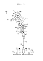
- FIG. 1 is a schematic view illustrating an overall configuration of the winding device 100.
- White arrows in the drawing indicate a feeding direction of a spun yarn Y.
- FIG. 2 and FIG. 3 are side views each illustrating a yarn joining operation of the winding device 100.
- the winding device 100 includes a yarn supplying section 1.
- a yarn supplying bobbin SB, around which the spun yarn Y is wound, is set in the yarn supplying section 1.
- the winding device 100 includes a yarn unwinding assisting section 2, a tension applying section 3, a tension detecting section 4, a yarn joining section 5, a yarn detecting section 6, a traversing section 7, and a winding section 8 along the feeding direction of the spun yarn Y unwound from the yarn supplying bobbin SB.
- the winding device 100 includes an upper yarn guiding section 9, a lower yarn guiding section 10, and a control section 11.
- the yarn unwinding assisting section 2 assists the unwinding of the spun yarn Y wound around the yarn supplying bobbin SB.
- the yarn unwinding assisting section 2 restricts the spun yarn Y unwound from the yarn supplying bobbin SB from spreading by centrifugal force.
- the tension applying section 3 applies a predetermined tension on the spun yarn Y unwound from the yarn supplying bobbin SB.
- the tension applying section 3 enables high-speed winding of the spun yarn Y by applying a predetermined tension on the spun yarn Y.
- a disc-type tensor, and the like may also be employed in addition to a gate-type tensor that applies the tension on the spun yarn Y by comb teeth.
- the tension detecting section 4 detects the tension applied on the spun yarn Y.
- the tension detecting section 4 can detect the tension applied on the spun yarn Y based on a voltage value that changes according to the tension of the spun yarn Y.
- a unit control section 11c analyzes a detection signal from the tension detecting section 4 to grasp the tension applied on the spun yarn Y.
- the yarn joining section 5 joins ends of the spun yarn Y to each other. When the spun yarn Y is broken, for example, the yarn joining section 5 joins the ends of the disconnected spun yarn Y to each other.
- a mechanical splicer and the like having a disc-type joining mechanism may be employed in addition to an air splicer that joins the ends of the spun yarn Y by a whirling airflow.
- the yarn detecting section 6 detects a defective part of the spun yarn Y.
- the yarn detecting section 6 detects yarn breakage of the spun yarn Y.
- the yarn detecting section 6 irradiates the spun yarn Y with a light emitting diode as a light source, and detects the defective part of the spun yarn Y and the yarn breakage of the spun yarn Y based on a reflected light quantity from the spun yarn Y.
- an analyzer 61 analyzes a detection signal from the yarn detecting section 6 to determine presence or absence of the defective part and presence or absence of the yarn breakage.
- a cutter 62 capable of cutting the spun yarn Y is provided in proximity to the yarn detecting section 6.
- the unit control section 11c can grasp the yarn breakage of the spun yarn Y by a cutting signal of the spun yarn Y by the cutter 62.
- the defective part of the spun yarn Y includes a case where foreign substances are contained in the spun yarn Y in addition to abnormality in which a portion of the spun yarn Y is too thick (thick yarn) or too thin (thin yarn).
- the yarn breakage of the spun yarn Y is a concept that includes a case where the spun yarn Y is cut by the cutter 62, a case where the spun yarn Y wound around the yarn supplying bobbin SB is entirely unwound, and a case where the spun yarn Y is broken by application of an excessive tension on the spun yarn Y.
- a capacitance sensor and the like may be employed in addition to an optical sensor described above.
- the traversing section 7 traverses the spun yarn Y guided to a package P.
- the traversing section 7 includes a traverse guide 71 and a traverse guide driving unit 72.
- the traverse guide driving unit 72 drives the traverse guide 71 based on a control signal from a traverse guide drive control section 11a.
- the traverse guide drive control section 11a transmits the control signal to the traverse guide driving unit 72 based on an instruction from the unit control section 11c.
- the unit control section 11c includes a determination section 11d adapted to determine whether or not the spun yarn Y wound around the yarn supplying bobbin SB can be unwound, that is, whether or not the yarn supplying bobbin SB is abnormal.
- the control section 11 has a concept including the traverse guide drive control section 11a, the unit control section 11c, and the determination section 11d.
- the traverse guide 71 is an arm member provided with a hooking section adapted to hook the spun yarn Y.
- the traverse guide 71 reciprocates in a rotation axis direction of a bobbin TB with the spun yarn Y hooked to the hooking section to traverse the spun yarn Y.
- the traverse guide driving unit 72 is mainly configured by a servomotor.
- the traverse guide driving unit 72 reciprocates the traverse guide 71 by forwardly rotating or reversely rotating a rotation shaft of the servomotor.
- the traverse guide driving unit 72 uses a servomotor for a power source, but for example, a stepping motor or the like may also be used, and any type of motor can be used.
- the traversing section 7 thus configures a so-called arm-type traverse device adapted to traverse the spun yarn Y by the reciprocating traverse guide 71.
- a belt-type traverse device, a blade traverse device, and the like can be used in addition to the arm-type traverse device.
- the winding device 100 may employ a traverse drum method, i.e., a structure in which a drum that rotates while making contact with the package P is arranged to traverse the spun yarn Y by a guiding groove formed on a surface of the drum.
- the winding section 8 winds the spun yarn Y by rotating the bobbin TB.
- the winding section 8 includes a bobbin holding unit 81, a contact roller 82, and a package driving unit 83.
- the package driving unit 83 rotates the bobbin TB based on a control signal from a package drive control section 11b.
- the package drive control section 11b transmits the control signal to the package driving unit 83 based on an instruction from the unit control section 11c.
- the unit control section 11c includes a determination section 11d adapted to determine whether or not the spun yarn Y wound around the yarn supplying bobbin SB can be unwound, that is, whether or not the yarn supplying bobbin SB is abnormal.
- the control section 11 has a concept including the package drive control section 11b, the unit control section 11c, and the determination section 11d.
- the bobbin holding unit 81 includes a bearing for removably clamping the bobbin TB, and rotatably holds the bobbin TB.
- the bobbin holding unit 81 can swing with a swing shaft 84 as center (see arrow in FIG. 2 ). Therefore, even if an outer diameter of the package P becomes large accompanying winding of the spun yarn Y, the bobbin holding unit 81 enables the contact roller 82 to push the surface of the package P at a prescribed load.
- the contact roller 82 rotates accompanying the rotation of the rotating package P.
- the contact roller 82 adjusts a shape of the package P by pressing the surface of the package P.
- the contact roller 82 is a substantially cylindrical rotating body, but may also be a conical rotating body, for example, and may be of any shape.
- the package driving unit 83 is mainly configured by a servomotor.
- the package driving unit 83 drives the servomotor to rotate the bobbin TB and the package P formed on the bobbin TB.
- the package driving unit 83 uses a servomotor for the power source, but for example, a stepping motor or the like may also be used, and any type of motor can be used.
- the winding section 8 is configured such that the package P is rotated by the package driving unit 83, and a contact roller 82 is rotated accompanying the rotation of the package P.
- the contact roller 82 may be rotated by the package driving unit 83, and the package P may be rotated accompanying the rotation of the contact roller 82.
- the upper yarn guiding section 9 catches a yarn end (upper yarn) YE of the spun yarn Y wound into the package P.
- the upper yarn guiding section 9 is swung while sucking and holding the yarn end YE to pull out the spun yarn Y from the package P.
- the upper yarn guiding section 9 is swung when the yarn joining operation is started (see arrow in FIG. 2 ), and catches the yarn end YE by sucking air from a suction opening 9a.
- the upper yarn guiding section 9 is swung while sucking and holding the yarn end YE (see arrow in FIG. 3 ) to pull out the spun yarn Y from the package P.
- the package driving unit 83 reversely rotates the bobbin TB and the package P (see arrow in FIG. 3 ).
- the lower yarn guiding section 10 catches the yarn end (lower yarn) YE of the spun yarn Y wound around the yarn supplying bobbin SB.
- the lower yarn guiding section 10 is swung while sucking and holding the yarn end YE to unwind the spun yarn Y from the yarn supplying bobbin SB.
- the lower yarn guiding section 10 catches the yarn end YE by sucking air from a suction opening 10a.
- the lower yarn guiding section 10 is swung while sucking and holding the yarn end YE (see arrow in FIG. 3 ) to unwind the spun yarn Y from the yarn supplying bobbin SB.
- the spun yarn Y arranged at a predetermined position by the upper yarn guiding section 9 and the spun yarn Y arranged at a predetermined position by the lower yarn guiding section 10 are joined by the yarn joining section 5.
- the winding device 100 resumes the formation of the package P.
- the winding device 100 includes a yarn supplying bobbin supplying section 12.
- the yarn supplying bobbin supplying section 12 can supply a new yarn supplying bobbin SB to the yarn supplying section 1 based on an instruction from the control section 11.
- the winding device 100 includes a yarn supplying bobbin collecting section 13.
- the yarn supplying bobbin collecting section 13 can collect the yarn supplying bobbin SB discharged from the winding device 100.
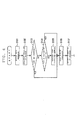
- FIG. 4 to FIG. 6 are flowcharts illustrating a control mode of the winding device 100.
- FIG. 4 illustrates a control mode at the time of a first yarn breakage.
- FIG. 5 illustrates a first control mode at the time of a second yarn breakage.
- FIG. 6 illustrates a second control mode at the time of the second yarn breakage.
- control mode at the time of the first yarn breakage and the first control mode at the time of the second yarn breakage will be described with reference to FIG. 4 and FIG. 5 .
- the yarn detecting section 6 detects the yarn breakage of the spun yarn Y in step S101.
- the control section 11 grasps that the spun yarn Y is broken based on an analysis result of the analyzer 61.
- the determination section 11d stores a tension value of when the spun yarn Y is broken based on a detection signal from the tension detecting section 4.
- step S102 the control section 11 interrupts the formation (winding) of the package P. Specifically, the control section 11 stops the rotation of the package P by transmitting a control signal to the package driving unit 83. The control section 11 thus interrupts the formation of the package P by stopping the rotation of the package P.
- step S103 the control section 11 considers whether or not the spun yarn Y is cut by the cutter 62. Specifically, the control section 11 grasps whether or not the spun yarn Y is cut by the cutter 62 based on the presence or absence of a cutting signal. If the spun yarn Y is cut by the cutter 62, the process proceeds to step S106, and if the spun yarn Y is not cut by the cutter 62, the process proceeds to step S104.
- a case where the spun yarn Y is cut by the cutter 62 is assumed to be a state in which the spun yarn Y is cut to remove the defective part.
- a case where the spun yarn Y is not cut by the cutter 62 is assumed to be a state in which the spun yarn Y wound around the yarn supplying bobbin SB is entirely unwound or a state in which the spun yarn Y is broken by application of an excessive tension on the spun yarn Y.
- step S104 the determination section 11d considers whether or not the spun yarn Y is broken by application of an excessive tension on the spun yarn Y. Specifically, the determination section 11d grasps whether or not the spun yarn Y is broken by application of an excessive tension based on the tension value stored in step S101. When the tension value stored in step S101 is greater than or equal to a predetermined value, the determination section 11d determines that the spun yarn Y is broken by application of an excessive tension on the spun yarn Y. If the spun yarn Y is broken by application of an excessive tension on the spun yarn Y, the process proceeds to step S106, and if the spun yarn Y is broken without application of an excessive tension on the spun yarn Y, the process proceeds to step S105.
- a case where the spun yarn Y is broken by application of an excessive tension on the spun yarn Y is assumed, for example, to be a state in which the spun yarn Y is caught or entangled at the flaw of the yarn supplying bobbin SB.
- a case where the spun yarn Y is broken without application of an excessive tension on the spun yarn Y is assumed to be a state in which the spun yarn Y wound around the yarn supplying bobbin SB is entirely unwound.
- step S105 the control section 11 replaces the yarn supplying bobbin SB. Specifically, the control section 11 instructs the discharge of the yarn supplying bobbin SB to the yarn supplying section 1 and instructs the supply of a new yarn supplying bobbin SB to the yarn supplying bobbin supplying section 12 (see black arrows in FIG. 2 and FIG. 3 ).
- step S106 the control section 11 joins the spun yarn Y from the yarn supplying section 1 and the spun yarn Y from the winding section 8. That is, the control section 11 joins the spun yarn Y wound around the yarn supplying bobbin SB and the spun yarn Y wound around the package P.
- the operation of joining the spun yarns Y that is, the yarn joining operation is an operation of arranging the spun yarns Y by the upper yarn guiding section 9 and the lower yarn guiding section 10, and joining the spun yarns Y by the yarn joining section 5.
- step S107 the control section 11 resumes the formation of the package P. Specifically, the control section 11 rotates the package P by transmitting a control signal to the package driving unit 83. The control section 11 thus resumes the formation of the package P by rotating the package P.
- the winding device 100 enables the formation of the package P to continue.
- the spun yarn Y is broken by application of an excessive tension on the spun yarn Y
- the spun yarn Y is broken by application of an excessive tension on the spun yarn Y when the spun yarn Y is caught or entangled at the flaw of the yarn supplying bobbin SB, even if the formation of the package P is resumed, the spun yarn Y may break again by application of an abnormal tension (in the second yarn breakage, this is referred to as "abnormal tension" for simplification.
- an abnormal tension in the second yarn breakage
- step S111 the control section 11 grasps that the spun yarn Y is again broken based on the analysis result of the analyzer 61.
- the determination section 11d stores the tension value of when the spun yarn Y is broken, similarly to the case of the first yarn breakage.
- step S112 the control section 11 interrupts the formation of the package P. As described above, the control section 11 interrupts the formation of the package P by stopping the rotation of the package P.
- step S113 the control section 11 considers whether or not the spun yarn Y is cut by the cutter 62. Specifically, the control section 11 grasps whether or not the spun yarn Y is cut by the cutter 62 based on presence or absence of the cutting signal. If the spun yarn Y is cut by the cutter 62, the process proceeds to step S117, and if the spun yarn Y is not cut by the cutter 62, the process proceeds to step S114.
- a case where the spun yarn Y is cut by the cutter 62 is assumed to be a state in which the spun yarn Y is cut to remove the defective part.
- a case where the spun yarn Y is not cut by the cutter 62 is assumed to be a state in which the spun yarn Y wound around the yarn supplying bobbin SB is entirely unwound or a state in which the spun yarn Y is broken by application of an abnormal tension on the spun yarn Y.
- step S114 the determination section 11d considers whether or not the spun yarn Y is broken by application of an abnormal tension on the spun yarn Y. Specifically, the determination section 11d grasps whether or not the spun yarn Y is broken by application of an abnormal tension based on the tension value stored in step S111. If the spun yarn Y is broken by application of an abnormal tension on the spun yarn Y, the process proceeds to step S115, and if the spun yarn Y is broken without application of an abnormal tension on the spun yarn Y, the process proceeds to step S116.
- a case where the spun yarn Y is broken by application of an abnormal tension on the spun yarn Y is assumed, for example, to be a state in which the spun yarn Y is caught or entangled at the flaw of the yarn supplying bobbin SB.
- a case where the spun yarn Y is broken without application of an abnormal tension on the spun yarn Y is assumed to be a state in which the spun yarn Y wound around the yarn supplying bobbin SB is entirely unwound.
- step S115 the determination section 11d considers whether or not an elapsed time after the formation of the package P is resumed until the yarn breakage of the spun yarn Y is detected is less than a predetermined time. Specifically, the determination section 11d grasps whether or not the elapsed time is less than the predetermined time by measuring the elapsed time after the formation of the package P is resumed until the yarn breakage of the spun yarn Y is detected. If the elapsed time is less than the predetermined time, the process proceeds to step S116, and if the elapsed time is not less than the predetermined time, the process proceeds to step S117. This makes the control mode different from the control mode at the time of the first yarn breakage.
- step S116 the control section 11 replaces the yarn supplying bobbin SB.
- the control section 11 instructs the discharge of the yarn supplying bobbin SB to the yarn supplying section 1 and instructs the supply of a new yarn supplying bobbin SB to the yarn supplying bobbin supplying section 12 (see black arrows in FIG. 2 and FIG. 3 ).
- step S117 the control section 11 joins the spun yarn Y from the yarn supplying section 1 and the spun yarn Y from the winding section 8.
- the operation of joining the spun yarns Y, that is, the yarn joining operation is as described above.
- step S118 the control section 11 resumes the formation of the package P.
- the control section 11 resumes the formation of the package P by rotating the package P.
- the yarn detecting section 6 again detects the yarn breakage of the spun yarn Y after resuming the formation of the package P and the tension detection section 4 detects a value greater than or equal to a predetermined value, and the elapsed time after the formation of the package P is resumed until the yarn breakage of the spun yarn Y is detected is less than the predetermined time, determination is made that the spun yarn Y wound around the yarn supplying bobbin SB cannot be unwound (see step S114 and step S115). Therefore, the winding device 100 promptly and accurately determines that the spun yarn Y wound around the yarn supplying bobbin SB cannot be unwound, that is, the yarn supplying bobbin SB is abnormal. In this control mode, determination is made as to whether or not the yarn supplying bobbin SB is abnormal when the second yarn breakage is detected, but the number of times the yarn breakage is detected is not limited thereto.
- the winding device 100 can promptly and accurately determine that the yarn supplying bobbin SB is abnormal. Accordingly, the repetition of the yarn joining operation can be avoided by replacing the yarn supplying bobbin SB, and the operation rate of the winding device 100 can be improved. The lowering of the quality of the package P can also be prevented.
- step S101 to step S107 is similar in the second control mode as well. Therefore, description will be made herein from step S211.
- step S211 the control section 11 grasps that the spun yarn Y is broken again based on the analysis result of the analyzer 61.
- the determination section 11d stores the tension value of when the spun yarn Y is broken, similarly to the first yarn breakage.
- step S212 the control section 11 interrupts the formation of the package P. As described above, the control section 11 interrupts the formation of the package P by stopping the rotation of the package P.
- step S213 the control section 11 considers whether or not the spun yarn Y is cut by the cutter 62. Specifically, the control section 11 grasps whether or not the spun yarn Y is cut by the cutter 62 based on the presence or absence of the cutting signal. If the spun yarn Y is cut by the cutter 62, the process proceeds to step S218, and if the spun yarn Y is not cut by the cutter 62, the process proceeds to step S214.
- a case where the spun yarn Y is cut by the cutter 62 is assumed to be a state in which the spun yarn Y is cut to remove the defective part.
- a case where the spun yarn Y is not cut by the cutter 62 is assumed to be a state in which the spun yarn Y wound around the yarn supplying bobbin SB is entirely unwound or a state in which the spun yarn Y is broken by application of an abnormal tension on the spun yarn Y.
- step S214 the determination section 11d considers whether or not the spun yarn Y is broken by application of an abnormal tension on the spun yarn Y. Specifically, the determination section 11d grasps whether or not the spun yarn Y is broken by application of an abnormal tension based on the tension value stored in step S211. If the spun yarn Y is broken by application of an abnormal tension on the spun yarn Y, the process proceeds to step S215, and if the spun yarn Y is broken without application of an abnormal tension on the spun yarn Y, the process proceeds to step S217.
- a case where the spun yarn Y is broken by application of an abnormal tension on the spun yarn Y is assumed, for example, to be a state in which the spun yarn Y is caught or entangled at the flaw of the yarn supplying bobbin SB.
- a case where the spun yarn Y is broken without application of an abnormal tension on the spun yarn Y is assumed to be a state in which the spun yarn Y wound around the yarn supplying bobbin SB is entirely unwound.
- step S215 as the cause of the first yarn breakage, the determination section 11d considers whether or not the spun yarn Y is broken by application of an excessive tension on the spun yarn Y. Specifically, the determination section 11d grasps whether or not the spun yarn Y is broken by application of an excessive tension based on the tension value stored in step S201 (corresponding to step S101). If the spun yarn Y is broken by application of an excessive tension on the spun yarn Y, the process proceeds to step S216, and if the spun yarn Y is broken without application of an excessive tension on the spun yarn Y, the process proceeds to step S218. This aspect makes the control mode different from the first control mode at the time of the second yarn breakage.
- step S216 the determination section 11d considers whether or not an elapsed time after the formation of the package P is resumed until the yarn breakage of the spun yarn Y is detected is less than a predetermined time. Specifically, the determination section 11d grasps whether or not the elapsed time is less than the predetermined time by measuring the elapsed time after the formation of the package P is resumed until the yarn breakage of the spun yarn Y is detected. If the relevant elapsed time is less than the predetermined time, the process proceeds to step S217, and if the relevant elapsed time is not less than the predetermined time, the process proceeds to step S218.
- step S217 the control section 11 replaces the yarn supplying bobbin SB.
- the control section 11 instructs the discharge of the yarn supplying bobbin SB to the yarn supplying section 1, and instructs the supply of a new yarn supplying bobbin SB to the yarn supplying bobbin supplying section 12 (see black arrows in FIG. 2 and FIG. 3 ).
- step S2108 the control section 11 joins the spun yarn Y from the yarn supplying section 1 and the spun yarn Y from the winding section 8.
- the operation of joining the spun yarns Y, that is, the yarn joining operation is as described above.
- step S219 the control section 11 resumes the formation of the package P.
- the control section 11 resumes the formation of the package P by rotating the package P.
- the yarn detecting section 6 again detects the yarn breakage of the spun yarn Y after resuming the formation of the package P and the tension detection section 4 detects a value greater than or equal to a predetermined value, and when the tension detection section 4 detects a value greater than or equal to a predetermined value before resuming the formation of the package P and the elapsed time after the formation of the package P is resumed until the yarn breakage of the spun yarn Y is detected is less than the predetermined time, determination is made that the spun yarn Y wound around the yarn supplying bobbin SB cannot be unwound (see step S214, step S215, and step S216).
- the winding device 100 promptly and accurately determines that the spun yarn Y wound around the yarn supplying bobbin SB cannot be unwound, that is, the yarn supplying bobbin SB is abnormal.
- determination is made as to whether or not the yarn supplying bobbin SB is abnormal when the second yarn breakage is detected, but the number of times the yarn breakage is detected is not limited thereto.
- the winding device 100 can promptly and accurately determine that the yarn supplying bobbin SB is abnormal. Accordingly, the repetition of the yarn joining operation can be avoided by replacing the yarn supplying bobbin SB, and the operation rate of the winding device 100 can be improved. The lowering of the quality of the package P can also be prevented.
- the winding device 100 can replace the yarn supplying bobbin SB by the instruction of the control section 11. This can be realized by including the yarn supplying bobbin supplying section 12 and the yarn supplying bobbin collecting section 13.
- the winding device 100 can discharge the yarn supplying bobbin SB, from which the spun yarn Y cannot be unwound, and can receive the supply of a new yarn supplying bobbin SB. Accordingly, the repetition of the yarn joining operation can be avoided, and the operation rate of the winding device 100 can be improved. Furthermore, the lowering of the quality of the package P can also be prevented.
Landscapes
- Engineering & Computer Science (AREA)
- Mechanical Engineering (AREA)
- Textile Engineering (AREA)
- Quality & Reliability (AREA)
- Filamentary Materials, Packages, And Safety Devices Therefor (AREA)
- Spinning Or Twisting Of Yarns (AREA)
- Replacing, Conveying, And Pick-Finding For Filamentary Materials (AREA)
Abstract
Description
- The present invention relates to a technique of a winding device adapted to wind a spun yarn to form a package.
- Conventionally, there is known a winding device adapted to wind a spun yarn unwound from a yarn supplying bobbin to form a package (see e.g., Japanese Patent No.
3714218 - When the yarn detecting section detects the defective part of the spun yarn, the winding device cuts the spun yarn and interrupts the formation of the package. Then, after removing the defective part, the winding device joins the disconnected spun yarn in the yarn joining section to resume the formation of the package.
- When the yarn detecting section detects the yarn breakage of the spun yarn, the winding device interrupts the formation of the package. Then, the winding device joins the disconnected spun yarn by the yarn joining section to resume the formation of the package. If the spun yarn wound around a yarn supplying bobbin is entirely unwound, the relevant spun yarn is joined with a spun yarn of a new yarn supplying bobbin to resume the formation of the package.
- If the spun yarn is broken by application of an excessive tension on the spun yarn, there is a high possibility that the spun yarn may break again even if the spun yarn is joined and the formation of the package is resumed. Since the spun yarn is broken by application of an excessive tension on the spun yarn when the spun yarn is caught or entangled at the flaw of the yarn supplying bobbin, the spun yarn will be broken again by application of an excessive tension on the spun yarn even if the formation of the package is resumed.
- Therefore, in the conventional winding device, a problem arises in that the yarn joining operation of the spun yarn is repeated, thereby lowering the operation rate. Furthermore, there also arises a problem in that the quality of the package lowers if the yarn joining operation is repeated. Therefore, to avoid the repetition of the yarn joining operation, there is desired a technique of promptly and accurately determining that the spun yarn wound around the yarn supplying bobbin cannot be unwound, that is, the yarn supplying bobbin is abnormal.
- An object of the present invention is to provide a technique capable of promptly and accurately determining that a yarn supplying bobbin is abnormal.
- A first aspect of the invention relates to a winding device including a yarn supplying section adapted to support a yarn supplying bobbin; a winding section adapted to wind a spun yarn unwound from the yarn supplying bobbin to form a package; a tension detecting section adapted to detect a tension of the spun yarn fed from the yarn supplying section to the winding section; a yarn detecting section adapted to detect yarn breakage of the spun yarn fed from the yarn supplying section to the winding section; a yarn joining section adapted to join a spun yarn from the yarn supplying section and a spun yarn from the winding section when the yarn detecting section detects the yarn breakage of the spun yarn; a control section adapted to cause the yarn joining section to join the spun yarn to resume the formation of the package; and a determination section adapted to determine that the yarn supplying bobbin is abnormal when the yarn detecting section detects the yarn breakage of the spun yarn and the tension detecting section detects a value greater than or equal to a predetermined value.
- A second aspect of the invention relates to the winding device according to the first aspect, wherein the determination section further determines that the yarn supplying bobbin is abnormal when the tension detecting section detects a value greater than or equal to a predetermined value upon yarn breakage immediately before the yarn joining section joins the spun yarn to resume the formation of the package.
- A third aspect of the invention relates to the winding device according to the first or second aspect, wherein the determination section further determines that the yarn supplying bobbin is abnormal when an elapsed time after the formation of the package is resumed until the yarn breakage of the spun yarn is detected is less than a predetermined time.
- A fourth aspect of the invention relates to the winding device according to any one of the first to third aspects, the device further including a yarn supplying bobbin supplying section adapted to supply a new yarn supplying bobbin to the yarn supplying section, wherein when the determination section determines that the yarn supplying bobbin is abnormal, the control section discharges the yarn supplying bobbin from the yarn supplying section and instructs the yarn supplying bobbin supplying section to supply a new yarn supplying bobbin.
- A fifth aspect of the invention relates to a winding method of a winding device adapted to wind a spun yarn unwound from a yarn supplying bobbin to form a package, the method including determining that the yarn supplying bobbin is in an abnormal state when the spun yarn is broken by application of an excessive tension after the spun yarn is joined to resume the formation of the package.
- A sixth aspect of the invention relates to the winding method according to the fifth aspect, the method including determining that the yarn supplying bobbin is in the abnormal state when an elapsed time after the formation of the package is resumed until the yarn breakage of the spun yarn is detected is less than a predetermined time.
- A seventh aspect of the invention relates to the winding method according to the fifth or sixth aspect, the method including discharging the yarn supplying bobbin and supplying a new yarn supplying bobbin when determined that the yarn supplying bobbin is in the abnormal state.
- The present invention has the following effects.
- According to the first aspect, determination can be made that the yarn supplying bobbin is abnormal. Accordingly, the repetition of the yarn joining operation can be avoided by replacing the yarn supplying bobbin, and the operation rate of the winding device can be improved. The lowering of the quality of the package can also be prevented.
- According to the second aspect, determination can be made promptly and accurately that the yarn supplying bobbin is abnormal. Accordingly, the repetition of the yarn joining operation can be avoided by replacing the yarn supplying bobbin, and the operation rate of the winding device can be improved. The lowering of the quality of the package can also be prevented.
- According to the third aspect, determination can be made promptly and accurately that the yarn supplying bobbin is abnormal. Accordingly, the repetition of the yarn joining operation can be avoided by replacing the yarn supplying bobbin, and the operation rate of the winding device can be improved. The lowering of the quality of the package can also be prevented.
- According to the fourth aspect, the yarn supplying bobbin that is determined as abnormal can be discharged, and a new yarn supplying bobbin can be supplied. Accordingly, the repetition of the yarn joining operation can be avoided, and the operation rate of the winding device can be improved. The lowering of the quality of the package can also be prevented.
- According to the fifth aspect, determination can be made that the yarn supplying bobbin is in an abnormal state. Accordingly, the repetition of the yarn joining operation can be avoided by replacing the yarn supplying bobbin, and the operation rate of the winding device can be improved. The lowering of the quality of the package can also be prevented.
- According to the sixth aspect, determination can be made promptly and accurately that the yarn supplying bobbin is abnormal. Accordingly, the repetition of the yarn joining operation can be avoided by replacing the yarn supplying bobbin, and the operation rate of the winding device can be improved. The lowering of the quality of the package can also be prevented.
- According to the seventh aspect, the yarn supplying bobbin that is determined to be in the abnormal state can be discharged and a new yarn supplying bobbin can be supplied. Accordingly, the repetition of the yarn joining operation can be avoided, and the operation rate of the winding device can be improved. The lowering of the quality of the package can also be prevented.
-
-
Fig. 1 is a schematic view illustrating an overall configuration of a winding device according to an embodiment of the present invention; -
Fig. 2 is a side view of the winding device at the beginning of a yarn joining operation when a new yarn supplying bobbin is fed; -
Fig. 3 is a side view of the winding device during the yarn joining operation; -
Fig. 4 is a flow chart illustrating a control mode at the time of a first yarn breakage; -
Fig. 5 is a flow chart illustrating a first control mode at the time of a second yarn breakage; and -
Fig. 6 is a flow chart illustrating a second control mode at the time of the second yarn breakage. - First, a
winding device 100 according to one embodiment of the present invention will be described. -
FIG. 1 is a schematic view illustrating an overall configuration of thewinding device 100. White arrows in the drawing indicate a feeding direction of a spun yarn Y.FIG. 2 andFIG. 3 are side views each illustrating a yarn joining operation of thewinding device 100. - The
winding device 100 includes ayarn supplying section 1. A yarn supplying bobbin SB, around which the spun yarn Y is wound, is set in theyarn supplying section 1. Thewinding device 100 includes a yarn unwinding assistingsection 2, atension applying section 3, atension detecting section 4, ayarn joining section 5, ayarn detecting section 6, a traversingsection 7, and awinding section 8 along the feeding direction of the spun yarn Y unwound from the yarn supplying bobbin SB. Furthermore, thewinding device 100 includes an upperyarn guiding section 9, a loweryarn guiding section 10, and acontrol section 11. - The yarn unwinding assisting
section 2 assists the unwinding of the spun yarn Y wound around the yarn supplying bobbin SB. The yarnunwinding assisting section 2 restricts the spun yarn Y unwound from the yarn supplying bobbin SB from spreading by centrifugal force. - The
tension applying section 3 applies a predetermined tension on the spun yarn Y unwound from the yarn supplying bobbin SB. Thetension applying section 3 enables high-speed winding of the spun yarn Y by applying a predetermined tension on the spun yarn Y. As thetension applying section 3, a disc-type tensor, and the like may also be employed in addition to a gate-type tensor that applies the tension on the spun yarn Y by comb teeth. - The
tension detecting section 4 detects the tension applied on the spun yarn Y. Thetension detecting section 4 can detect the tension applied on the spun yarn Y based on a voltage value that changes according to the tension of the spun yarn Y. Specifically, aunit control section 11c analyzes a detection signal from thetension detecting section 4 to grasp the tension applied on the spun yarn Y. - The
yarn joining section 5 joins ends of the spun yarn Y to each other. When the spun yarn Y is broken, for example, theyarn joining section 5 joins the ends of the disconnected spun yarn Y to each other. As theyarn joining section 5, a mechanical splicer and the like having a disc-type joining mechanism may be employed in addition to an air splicer that joins the ends of the spun yarn Y by a whirling airflow. - The
yarn detecting section 6 detects a defective part of the spun yarn Y. Theyarn detecting section 6 detects yarn breakage of the spun yarn Y. Theyarn detecting section 6 irradiates the spun yarn Y with a light emitting diode as a light source, and detects the defective part of the spun yarn Y and the yarn breakage of the spun yarn Y based on a reflected light quantity from the spun yarn Y. Specifically, ananalyzer 61 analyzes a detection signal from theyarn detecting section 6 to determine presence or absence of the defective part and presence or absence of the yarn breakage. Acutter 62 capable of cutting the spun yarn Y is provided in proximity to theyarn detecting section 6. Theunit control section 11c can grasp the yarn breakage of the spun yarn Y by a cutting signal of the spun yarn Y by thecutter 62. - Herein, the defective part of the spun yarn Y includes a case where foreign substances are contained in the spun yarn Y in addition to abnormality in which a portion of the spun yarn Y is too thick (thick yarn) or too thin (thin yarn). The yarn breakage of the spun yarn Y is a concept that includes a case where the spun yarn Y is cut by the
cutter 62, a case where the spun yarn Y wound around the yarn supplying bobbin SB is entirely unwound, and a case where the spun yarn Y is broken by application of an excessive tension on the spun yarn Y. As theyarn detecting section 6, a capacitance sensor and the like may be employed in addition to an optical sensor described above. - The
traversing section 7 traverses the spun yarn Y guided to a package P. Thetraversing section 7 includes atraverse guide 71 and a traverse guide driving unit 72. The traverse guide driving unit 72 drives thetraverse guide 71 based on a control signal from a traverse guidedrive control section 11a. The traverse guidedrive control section 11a transmits the control signal to the traverse guide driving unit 72 based on an instruction from theunit control section 11c. Theunit control section 11c includes adetermination section 11d adapted to determine whether or not the spun yarn Y wound around the yarn supplying bobbin SB can be unwound, that is, whether or not the yarn supplying bobbin SB is abnormal. Thecontrol section 11 has a concept including the traverse guidedrive control section 11a, theunit control section 11c, and thedetermination section 11d. - The
traverse guide 71 is an arm member provided with a hooking section adapted to hook the spun yarn Y. Thetraverse guide 71 reciprocates in a rotation axis direction of a bobbin TB with the spun yarn Y hooked to the hooking section to traverse the spun yarn Y. - The traverse guide driving unit 72 is mainly configured by a servomotor. The traverse guide driving unit 72 reciprocates the
traverse guide 71 by forwardly rotating or reversely rotating a rotation shaft of the servomotor. The traverse guide driving unit 72 uses a servomotor for a power source, but for example, a stepping motor or the like may also be used, and any type of motor can be used. - The
traversing section 7 thus configures a so-called arm-type traverse device adapted to traverse the spun yarn Y by thereciprocating traverse guide 71. However, a belt-type traverse device, a blade traverse device, and the like can be used in addition to the arm-type traverse device. The windingdevice 100 may employ a traverse drum method, i.e., a structure in which a drum that rotates while making contact with the package P is arranged to traverse the spun yarn Y by a guiding groove formed on a surface of the drum. - The winding
section 8 winds the spun yarn Y by rotating the bobbin TB. The windingsection 8 includes abobbin holding unit 81, acontact roller 82, and apackage driving unit 83. Thepackage driving unit 83 rotates the bobbin TB based on a control signal from a packagedrive control section 11b. The packagedrive control section 11b transmits the control signal to thepackage driving unit 83 based on an instruction from theunit control section 11c. As described above, theunit control section 11c includes adetermination section 11d adapted to determine whether or not the spun yarn Y wound around the yarn supplying bobbin SB can be unwound, that is, whether or not the yarn supplying bobbin SB is abnormal. Thecontrol section 11 has a concept including the packagedrive control section 11b, theunit control section 11c, and thedetermination section 11d. - The
bobbin holding unit 81 includes a bearing for removably clamping the bobbin TB, and rotatably holds the bobbin TB. Thebobbin holding unit 81 can swing with aswing shaft 84 as center (see arrow inFIG. 2 ). Therefore, even if an outer diameter of the package P becomes large accompanying winding of the spun yarn Y, thebobbin holding unit 81 enables thecontact roller 82 to push the surface of the package P at a prescribed load. - The
contact roller 82 rotates accompanying the rotation of the rotating package P. Thecontact roller 82 adjusts a shape of the package P by pressing the surface of the package P. Thecontact roller 82 is a substantially cylindrical rotating body, but may also be a conical rotating body, for example, and may be of any shape. - The
package driving unit 83 is mainly configured by a servomotor. Thepackage driving unit 83 drives the servomotor to rotate the bobbin TB and the package P formed on the bobbin TB. Thepackage driving unit 83 uses a servomotor for the power source, but for example, a stepping motor or the like may also be used, and any type of motor can be used. - As described above, the winding
section 8 is configured such that the package P is rotated by thepackage driving unit 83, and acontact roller 82 is rotated accompanying the rotation of the package P. However, thecontact roller 82 may be rotated by thepackage driving unit 83, and the package P may be rotated accompanying the rotation of thecontact roller 82. - For example, when the spun yarn Y is broken, the upper
yarn guiding section 9 catches a yarn end (upper yarn) YE of the spun yarn Y wound into the package P. The upperyarn guiding section 9 is swung while sucking and holding the yarn end YE to pull out the spun yarn Y from the package P. Specifically, the upperyarn guiding section 9 is swung when the yarn joining operation is started (see arrow inFIG. 2 ), and catches the yarn end YE by sucking air from asuction opening 9a. The upperyarn guiding section 9 is swung while sucking and holding the yarn end YE (see arrow inFIG. 3 ) to pull out the spun yarn Y from the package P. In this case, thepackage driving unit 83 reversely rotates the bobbin TB and the package P (see arrow inFIG. 3 ). - For example, when the spun yarn Y is broken, the lower
yarn guiding section 10 catches the yarn end (lower yarn) YE of the spun yarn Y wound around the yarn supplying bobbin SB. The loweryarn guiding section 10 is swung while sucking and holding the yarn end YE to unwind the spun yarn Y from the yarn supplying bobbin SB. Specifically, the loweryarn guiding section 10 catches the yarn end YE by sucking air from asuction opening 10a. The loweryarn guiding section 10 is swung while sucking and holding the yarn end YE (see arrow inFIG. 3 ) to unwind the spun yarn Y from the yarn supplying bobbin SB. - Subsequently, the spun yarn Y arranged at a predetermined position by the upper
yarn guiding section 9 and the spun yarn Y arranged at a predetermined position by the loweryarn guiding section 10 are joined by theyarn joining section 5. In this manner, the windingdevice 100 resumes the formation of the package P. - As illustrated in
FIG. 2 andFIG. 3 , the windingdevice 100 includes a yarn supplyingbobbin supplying section 12. The yarn supplyingbobbin supplying section 12 can supply a new yarn supplying bobbin SB to theyarn supplying section 1 based on an instruction from thecontrol section 11. Furthermore, the windingdevice 100 includes a yarn supplyingbobbin collecting section 13. The yarn supplyingbobbin collecting section 13 can collect the yarn supplying bobbin SB discharged from the windingdevice 100. - Next, a technique capable of promptly and accurately determining that the spun yarn Y wound around the yarn supplying bobbin SB cannot be unwound will be described.
-
FIG. 4 to FIG. 6 are flowcharts illustrating a control mode of the windingdevice 100.FIG. 4 illustrates a control mode at the time of a first yarn breakage.FIG. 5 illustrates a first control mode at the time of a second yarn breakage.FIG. 6 illustrates a second control mode at the time of the second yarn breakage. - First, the control mode at the time of the first yarn breakage and the first control mode at the time of the second yarn breakage will be described with reference to
FIG. 4 andFIG. 5 . - Assume that the
yarn detecting section 6 detects the yarn breakage of the spun yarn Y in step S101. Specifically, assume that thecontrol section 11 grasps that the spun yarn Y is broken based on an analysis result of theanalyzer 61. In this case, thedetermination section 11d stores a tension value of when the spun yarn Y is broken based on a detection signal from thetension detecting section 4. - In step S102, the
control section 11 interrupts the formation (winding) of the package P. Specifically, thecontrol section 11 stops the rotation of the package P by transmitting a control signal to thepackage driving unit 83. Thecontrol section 11 thus interrupts the formation of the package P by stopping the rotation of the package P. - In step S103, the
control section 11 considers whether or not the spun yarn Y is cut by thecutter 62. Specifically, thecontrol section 11 grasps whether or not the spun yarn Y is cut by thecutter 62 based on the presence or absence of a cutting signal. If the spun yarn Y is cut by thecutter 62, the process proceeds to step S106, and if the spun yarn Y is not cut by thecutter 62, the process proceeds to step S104. - A case where the spun yarn Y is cut by the
cutter 62 is assumed to be a state in which the spun yarn Y is cut to remove the defective part. A case where the spun yarn Y is not cut by thecutter 62 is assumed to be a state in which the spun yarn Y wound around the yarn supplying bobbin SB is entirely unwound or a state in which the spun yarn Y is broken by application of an excessive tension on the spun yarn Y. - In step S104, the
determination section 11d considers whether or not the spun yarn Y is broken by application of an excessive tension on the spun yarn Y. Specifically, thedetermination section 11d grasps whether or not the spun yarn Y is broken by application of an excessive tension based on the tension value stored in step S101. When the tension value stored in step S101 is greater than or equal to a predetermined value, thedetermination section 11d determines that the spun yarn Y is broken by application of an excessive tension on the spun yarn Y. If the spun yarn Y is broken by application of an excessive tension on the spun yarn Y, the process proceeds to step S106, and if the spun yarn Y is broken without application of an excessive tension on the spun yarn Y, the process proceeds to step S105. - A case where the spun yarn Y is broken by application of an excessive tension on the spun yarn Y is assumed, for example, to be a state in which the spun yarn Y is caught or entangled at the flaw of the yarn supplying bobbin SB. A case where the spun yarn Y is broken without application of an excessive tension on the spun yarn Y is assumed to be a state in which the spun yarn Y wound around the yarn supplying bobbin SB is entirely unwound.
- In step S105, the
control section 11 replaces the yarn supplying bobbin SB. Specifically, thecontrol section 11 instructs the discharge of the yarn supplying bobbin SB to theyarn supplying section 1 and instructs the supply of a new yarn supplying bobbin SB to the yarn supplying bobbin supplying section 12 (see black arrows inFIG. 2 andFIG. 3 ). - In step S106, the
control section 11 joins the spun yarn Y from theyarn supplying section 1 and the spun yarn Y from the windingsection 8. That is, thecontrol section 11 joins the spun yarn Y wound around the yarn supplying bobbin SB and the spun yarn Y wound around the package P. The operation of joining the spun yarns Y, that is, the yarn joining operation is an operation of arranging the spun yarns Y by the upperyarn guiding section 9 and the loweryarn guiding section 10, and joining the spun yarns Y by theyarn joining section 5. - In step S107, the
control section 11 resumes the formation of the package P. Specifically, thecontrol section 11 rotates the package P by transmitting a control signal to thepackage driving unit 83. Thecontrol section 11 thus resumes the formation of the package P by rotating the package P. - According to such a control mode, the winding
device 100 enables the formation of the package P to continue. However, if the spun yarn Y is broken by application of an excessive tension on the spun yarn Y, there is a high possibility that the spun yarn Y may break again even if the spun yarns Y are joined and the formation of the package P is resumed. Since the spun yarn Y is broken by application of an excessive tension on the spun yarn Y when the spun yarn Y is caught or entangled at the flaw of the yarn supplying bobbin SB, even if the formation of the package P is resumed, the spun yarn Y may break again by application of an abnormal tension (in the second yarn breakage, this is referred to as "abnormal tension" for simplification. The "excessive tension" and the "abnormal tension" are synonymous). - In step S111, the
control section 11 grasps that the spun yarn Y is again broken based on the analysis result of theanalyzer 61. In this case, thedetermination section 11d stores the tension value of when the spun yarn Y is broken, similarly to the case of the first yarn breakage. - In step S112, the
control section 11 interrupts the formation of the package P. As described above, thecontrol section 11 interrupts the formation of the package P by stopping the rotation of the package P. - In step S113, the
control section 11 considers whether or not the spun yarn Y is cut by thecutter 62. Specifically, thecontrol section 11 grasps whether or not the spun yarn Y is cut by thecutter 62 based on presence or absence of the cutting signal. If the spun yarn Y is cut by thecutter 62, the process proceeds to step S117, and if the spun yarn Y is not cut by thecutter 62, the process proceeds to step S114. - A case where the spun yarn Y is cut by the
cutter 62 is assumed to be a state in which the spun yarn Y is cut to remove the defective part. A case where the spun yarn Y is not cut by thecutter 62 is assumed to be a state in which the spun yarn Y wound around the yarn supplying bobbin SB is entirely unwound or a state in which the spun yarn Y is broken by application of an abnormal tension on the spun yarn Y. - In step S114, the
determination section 11d considers whether or not the spun yarn Y is broken by application of an abnormal tension on the spun yarn Y. Specifically, thedetermination section 11d grasps whether or not the spun yarn Y is broken by application of an abnormal tension based on the tension value stored in step S111. If the spun yarn Y is broken by application of an abnormal tension on the spun yarn Y, the process proceeds to step S115, and if the spun yarn Y is broken without application of an abnormal tension on the spun yarn Y, the process proceeds to step S116. - A case where the spun yarn Y is broken by application of an abnormal tension on the spun yarn Y is assumed, for example, to be a state in which the spun yarn Y is caught or entangled at the flaw of the yarn supplying bobbin SB. A case where the spun yarn Y is broken without application of an abnormal tension on the spun yarn Y is assumed to be a state in which the spun yarn Y wound around the yarn supplying bobbin SB is entirely unwound.
- In step S115, the
determination section 11d considers whether or not an elapsed time after the formation of the package P is resumed until the yarn breakage of the spun yarn Y is detected is less than a predetermined time. Specifically, thedetermination section 11d grasps whether or not the elapsed time is less than the predetermined time by measuring the elapsed time after the formation of the package P is resumed until the yarn breakage of the spun yarn Y is detected. If the elapsed time is less than the predetermined time, the process proceeds to step S116, and if the elapsed time is not less than the predetermined time, the process proceeds to step S117. This makes the control mode different from the control mode at the time of the first yarn breakage. - In a case where the first yarn breakage is caused by application of an excessive tension on the spun yarn Y and the elapsed time after the formation of the package P is resumed until the second yarn breakage is detected is less than the predetermined time, it is assumed that the spun yarn Y is caught or entangled at the flaw of the yarn supplying bobbin SB.
- In step S116, the
control section 11 replaces the yarn supplying bobbin SB. As described above, thecontrol section 11 instructs the discharge of the yarn supplying bobbin SB to theyarn supplying section 1 and instructs the supply of a new yarn supplying bobbin SB to the yarn supplying bobbin supplying section 12 (see black arrows inFIG. 2 andFIG. 3 ). - In step S117, the
control section 11 joins the spun yarn Y from theyarn supplying section 1 and the spun yarn Y from the windingsection 8. The operation of joining the spun yarns Y, that is, the yarn joining operation is as described above. - In step S118, the
control section 11 resumes the formation of the package P. Thecontrol section 11 resumes the formation of the package P by rotating the package P. - As described above, in the first control mode, when the
yarn detecting section 6 again detects the yarn breakage of the spun yarn Y after resuming the formation of the package P and thetension detection section 4 detects a value greater than or equal to a predetermined value, and the elapsed time after the formation of the package P is resumed until the yarn breakage of the spun yarn Y is detected is less than the predetermined time, determination is made that the spun yarn Y wound around the yarn supplying bobbin SB cannot be unwound (see step S114 and step S115). Therefore, the windingdevice 100 promptly and accurately determines that the spun yarn Y wound around the yarn supplying bobbin SB cannot be unwound, that is, the yarn supplying bobbin SB is abnormal. In this control mode, determination is made as to whether or not the yarn supplying bobbin SB is abnormal when the second yarn breakage is detected, but the number of times the yarn breakage is detected is not limited thereto. - According to such a control mode, the winding
device 100 can promptly and accurately determine that the yarn supplying bobbin SB is abnormal. Accordingly, the repetition of the yarn joining operation can be avoided by replacing the yarn supplying bobbin SB, and the operation rate of the windingdevice 100 can be improved. The lowering of the quality of the package P can also be prevented. - Next, the second control mode at the time of the second yarn breakage will be described with reference to
FIG. 6 . - In the second control mode as well, the control mode at the time of the first yarn breakage is similar to the control mode described above. In other words, the configuration from step S101 to step S107 is similar in the second control mode as well. Therefore, description will be made herein from step S211.
- In step S211, the
control section 11 grasps that the spun yarn Y is broken again based on the analysis result of theanalyzer 61. In this case, thedetermination section 11d stores the tension value of when the spun yarn Y is broken, similarly to the first yarn breakage. - In step S212, the
control section 11 interrupts the formation of the package P. As described above, thecontrol section 11 interrupts the formation of the package P by stopping the rotation of the package P. - In step S213, the
control section 11 considers whether or not the spun yarn Y is cut by thecutter 62. Specifically, thecontrol section 11 grasps whether or not the spun yarn Y is cut by thecutter 62 based on the presence or absence of the cutting signal. If the spun yarn Y is cut by thecutter 62, the process proceeds to step S218, and if the spun yarn Y is not cut by thecutter 62, the process proceeds to step S214. - A case where the spun yarn Y is cut by the
cutter 62 is assumed to be a state in which the spun yarn Y is cut to remove the defective part. A case where the spun yarn Y is not cut by thecutter 62 is assumed to be a state in which the spun yarn Y wound around the yarn supplying bobbin SB is entirely unwound or a state in which the spun yarn Y is broken by application of an abnormal tension on the spun yarn Y. - In step S214, the
determination section 11d considers whether or not the spun yarn Y is broken by application of an abnormal tension on the spun yarn Y. Specifically, thedetermination section 11d grasps whether or not the spun yarn Y is broken by application of an abnormal tension based on the tension value stored in step S211. If the spun yarn Y is broken by application of an abnormal tension on the spun yarn Y, the process proceeds to step S215, and if the spun yarn Y is broken without application of an abnormal tension on the spun yarn Y, the process proceeds to step S217. - A case where the spun yarn Y is broken by application of an abnormal tension on the spun yarn Y is assumed, for example, to be a state in which the spun yarn Y is caught or entangled at the flaw of the yarn supplying bobbin SB. A case where the spun yarn Y is broken without application of an abnormal tension on the spun yarn Y is assumed to be a state in which the spun yarn Y wound around the yarn supplying bobbin SB is entirely unwound.
- In step S215, as the cause of the first yarn breakage, the
determination section 11d considers whether or not the spun yarn Y is broken by application of an excessive tension on the spun yarn Y. Specifically, thedetermination section 11d grasps whether or not the spun yarn Y is broken by application of an excessive tension based on the tension value stored in step S201 (corresponding to step S101). If the spun yarn Y is broken by application of an excessive tension on the spun yarn Y, the process proceeds to step S216, and if the spun yarn Y is broken without application of an excessive tension on the spun yarn Y, the process proceeds to step S218. This aspect makes the control mode different from the first control mode at the time of the second yarn breakage. - In a case where the first and second yarn breakages are caused by application of an excessive (abnormal) tension on the spun yarn Y, it is reliably assumed that the spun yarn Y is caught or entangled at the flaw of the yarn supplying bobbin SB.
- In step S216, the
determination section 11d considers whether or not an elapsed time after the formation of the package P is resumed until the yarn breakage of the spun yarn Y is detected is less than a predetermined time. Specifically, thedetermination section 11d grasps whether or not the elapsed time is less than the predetermined time by measuring the elapsed time after the formation of the package P is resumed until the yarn breakage of the spun yarn Y is detected. If the relevant elapsed time is less than the predetermined time, the process proceeds to step S217, and if the relevant elapsed time is not less than the predetermined time, the process proceeds to step S218. - In a case where the first yarn breakage is caused by application of an excessive tension on the spun yarn Y and the elapsed time after the formation of the package P is resumed until the second yarn breakage is detected is less than the predetermined time, it is reliably assumed that the spun yarn Y is caught or entangled at the flaw of the yarn supplying bobbin SB.
- In step S217, the
control section 11 replaces the yarn supplying bobbin SB. As described above, thecontrol section 11 instructs the discharge of the yarn supplying bobbin SB to theyarn supplying section 1, and instructs the supply of a new yarn supplying bobbin SB to the yarn supplying bobbin supplying section 12 (see black arrows inFIG. 2 andFIG. 3 ). - In step S218, the
control section 11 joins the spun yarn Y from theyarn supplying section 1 and the spun yarn Y from the windingsection 8. The operation of joining the spun yarns Y, that is, the yarn joining operation is as described above. - In step S219, the
control section 11 resumes the formation of the package P. Thecontrol section 11 resumes the formation of the package P by rotating the package P. - As described above, in the second control mode, when the
yarn detecting section 6 again detects the yarn breakage of the spun yarn Y after resuming the formation of the package P and thetension detection section 4 detects a value greater than or equal to a predetermined value, and when thetension detection section 4 detects a value greater than or equal to a predetermined value before resuming the formation of the package P and the elapsed time after the formation of the package P is resumed until the yarn breakage of the spun yarn Y is detected is less than the predetermined time, determination is made that the spun yarn Y wound around the yarn supplying bobbin SB cannot be unwound (see step S214, step S215, and step S216). Therefore, the windingdevice 100 promptly and accurately determines that the spun yarn Y wound around the yarn supplying bobbin SB cannot be unwound, that is, the yarn supplying bobbin SB is abnormal. In this control mode, determination is made as to whether or not the yarn supplying bobbin SB is abnormal when the second yarn breakage is detected, but the number of times the yarn breakage is detected is not limited thereto. - According to such a control mode, the winding
device 100 can promptly and accurately determine that the yarn supplying bobbin SB is abnormal. Accordingly, the repetition of the yarn joining operation can be avoided by replacing the yarn supplying bobbin SB, and the operation rate of the windingdevice 100 can be improved. The lowering of the quality of the package P can also be prevented. - As described above, the winding
device 100 can replace the yarn supplying bobbin SB by the instruction of thecontrol section 11. This can be realized by including the yarn supplyingbobbin supplying section 12 and the yarn supplyingbobbin collecting section 13. - According to such a configuration, the winding
device 100 can discharge the yarn supplying bobbin SB, from which the spun yarn Y cannot be unwound, and can receive the supply of a new yarn supplying bobbin SB. Accordingly, the repetition of the yarn joining operation can be avoided, and the operation rate of the windingdevice 100 can be improved. Furthermore, the lowering of the quality of the package P can also be prevented.
Claims (7)
- A winding device (100) characterized by comprising:a yarn supplying section (1) adapted to support a yarn supplying bobbin (SB);a winding section (8) adapted to wind a spun yarn (Y) unwound from the yarn supplying bobbin (SB) to form a package (P);a tension detecting section (4) adapted to detect a tension of the spun yarn (Y) fed from the yarn supplying section (1) to the winding section (8);a yarn detecting section (6) adapted to detect yarn breakage of the spun yarn (Y) fed from the yarn supplying section (1) to the winding section (8);a yarn joining section (5) adapted to join a spun yarn (Y) from the yarn supplying section (1) and a spun yarn from the winding section (8) when the yarn detecting section (6) detects the yarn breakage of the spun yarn (Y);a control section (11) adapted to cause the yarn joining section (5) to join the spun yarn (Y) to resume the formation of the package (P); anda determination section (11d) adapted to determine that the yarn supplying bobbin (SB) is abnormal when the yarn detecting section (6) detects the yarn breakage of the spun yarn (Y) and the tension detecting section (4) detects a value greater than or equal to a predetermined value.
- The winding device (100) according to claim 1, characterized in that the determination section (11d) determines that the yarn supplying bobbin (SB) is abnormal when the tension detecting section (4) detects a value greater than or equal to a predetermined value upon yarn breakage immediately before the yarn joining section (5) joins the spun yarn (Y) to resume the formation of the package.
- The winding device (100) according to claim 1 or 2,
characterized in that the determination section (11d) determines that the yarn supplying bobbin (SB) is abnormal
when an elapsed time after the formation of the package (P) is resumed until the yarn breakage of the spun yarn is detected is less than a predetermined time. - The winding device (100) according to any one of claims 1 to 3, further characterized by comprising a yarn supplying bobbin supplying section (12) adapted to supply a new yarn supplying bobbin (SB) to the yarn supplying section (1), wherein
when the determination section (11d) determines that the yarn supplying bobbin (SB) is abnormal, the control section (11) discharges the yarn supplying bobbin (SB) from the yarn supplying section (1) and instructs the yarn supplying bobbin supplying section (12) to supply a new yarn supplying bobbin (SB). - A winding method for a winding device (100) adapted to wind a spun yarn (Y) unwound from a yarn supplying bobbin (SB) to form a package (P), the method characterized by comprising:determining that the yarn supplying bobbin (SB) is in an abnormal state when the spun yarn (Y) is broken by application of an excessive tension after the spun yarn (Y) is joined to resume the formation of the package (P).
- The winding method according to claim 5, characterized by comprising:determining that the yarn supplying bobbin (SB) is in the abnormal state when an elapsed time after the formation of the package (P) is resumed until the yarn breakage of the spun yarn (Y) is detected is less than a predetermined time.
- The winding method according to claim 5 or 6,
characterized by comprising:discharging the yarn supplying bobbin (SB) and supplying a new yarn supplying bobbin (SB) when it is determined that the yarn supplying bobbin (SB) is in the abnormal state.
Applications Claiming Priority (1)
| Application Number | Priority Date | Filing Date | Title |
|---|---|---|---|
| JP2012016794A JP2013154993A (en) | 2012-01-30 | 2012-01-30 | Winding device |
Publications (3)
| Publication Number | Publication Date |
|---|---|
| EP2620533A2 true EP2620533A2 (en) | 2013-07-31 |
| EP2620533A3 EP2620533A3 (en) | 2014-04-02 |
| EP2620533B1 EP2620533B1 (en) | 2015-07-15 |
Family
ID=47257574
Family Applications (1)
| Application Number | Title | Priority Date | Filing Date |
|---|---|---|---|
| EP12194098.5A Not-in-force EP2620533B1 (en) | 2012-01-30 | 2012-11-23 | Winding device |
Country Status (3)
| Country | Link |
|---|---|
| EP (1) | EP2620533B1 (en) |
| JP (1) | JP2013154993A (en) |
| CN (1) | CN103224168B (en) |
Cited By (1)
| Publication number | Priority date | Publication date | Assignee | Title |
|---|---|---|---|---|
| EP3828325A1 (en) * | 2019-11-29 | 2021-06-02 | Saurer Intelligent Technology AG | Spinning station and air spinning station comprising such a spinning station and process to determin a yarn strength defect |
Families Citing this family (3)
| Publication number | Priority date | Publication date | Assignee | Title |
|---|---|---|---|---|
| JP2017001780A (en) * | 2015-06-05 | 2017-01-05 | 村田機械株式会社 | Yarn winding system, automatic winder, spinning frame and yarn winding method |
| JP2019034814A (en) * | 2017-08-16 | 2019-03-07 | 村田機械株式会社 | Winder unit |
| EP3865441B1 (en) * | 2018-10-09 | 2023-07-12 | TMT Machinery, Inc. | Yarn winding machine |
Citations (1)
| Publication number | Priority date | Publication date | Assignee | Title |
|---|---|---|---|---|
| JP3714218B2 (en) | 2001-10-03 | 2005-11-09 | 村田機械株式会社 | Bobbin transfer system |
Family Cites Families (7)
| Publication number | Priority date | Publication date | Assignee | Title |
|---|---|---|---|---|
| BE640465A (en) * | 1962-12-11 | 1900-01-01 | ||
| DE3842381A1 (en) * | 1988-12-16 | 1990-06-28 | Schlafhorst & Co W | METHOD AND DEVICE FOR DETECTING THE DISCHARGE PROPERTIES OF DRAIN COILS |
| EP0427990B1 (en) * | 1989-11-14 | 1994-12-21 | W. SCHLAFHORST AG & CO. | Device for performing automatically thread splicing as well as cop changing, presenting operations in a fixed order, at a winding position of a winding machine |
| DE3937824A1 (en) * | 1989-11-14 | 1991-05-16 | Schlafhorst & Co W | Precision winder - has electronic control to prevent cop change when not empty or attempted threading up when cop tube is empty |
| DE4422596A1 (en) * | 1994-06-28 | 1996-01-04 | Schlafhorst & Co W | Bobbin winder |
| DE19848881A1 (en) * | 1998-10-23 | 2000-04-27 | Schlafhorst & Co W | Method for operating a work station of a winding machine |
| DE102009024037A1 (en) * | 2009-06-05 | 2010-12-09 | Oerlikon Textile Gmbh & Co. Kg | Method for eliminating a thread break at a workstation of a winder and workstation of a winder |
-
2012
- 2012-01-30 JP JP2012016794A patent/JP2013154993A/en active Pending
- 2012-11-23 EP EP12194098.5A patent/EP2620533B1/en not_active Not-in-force
-
2013
- 2013-01-30 CN CN201310036310.4A patent/CN103224168B/en not_active Expired - Fee Related
Patent Citations (1)
| Publication number | Priority date | Publication date | Assignee | Title |
|---|---|---|---|---|
| JP3714218B2 (en) | 2001-10-03 | 2005-11-09 | 村田機械株式会社 | Bobbin transfer system |
Cited By (2)
| Publication number | Priority date | Publication date | Assignee | Title |
|---|---|---|---|---|
| EP3828325A1 (en) * | 2019-11-29 | 2021-06-02 | Saurer Intelligent Technology AG | Spinning station and air spinning station comprising such a spinning station and process to determin a yarn strength defect |
| WO2021105382A1 (en) * | 2019-11-29 | 2021-06-03 | Saurer Intelligent Technology AG | Spinning unit and air jet spinning machine comprising such a spinning unit |
Also Published As
| Publication number | Publication date |
|---|---|
| JP2013154993A (en) | 2013-08-15 |
| CN103224168A (en) | 2013-07-31 |
| EP2620533A3 (en) | 2014-04-02 |
| CN103224168B (en) | 2016-12-28 |
| EP2620533B1 (en) | 2015-07-15 |
Similar Documents
| Publication | Publication Date | Title |
|---|---|---|
| EP2284300B1 (en) | Spinning machine and yarn removing method for removing yarn remaining on yarn accumulating roller | |
| CN108975070B (en) | Yarn monitoring device, yarn winding machine, and yarn monitoring method | |
| EP2479130B1 (en) | Yarn winding device | |
| EP2202192B1 (en) | Yarn winding device and automatic winder | |
| CN104925584B (en) | Yarn winding machine and winding method | |
| JP5636831B2 (en) | Fiber strip measuring device and yarn winding machine | |
| EP2690046B1 (en) | Yarn defect detecting device and winding device | |
| EP2620533B1 (en) | Winding device | |
| EP2573235B1 (en) | Spinning machine | |
| EP1882663A2 (en) | Device for pulling out a yarn end from a winding package | |
| EP2990367B1 (en) | Yarn winding device | |
| EP2573217A2 (en) | Spinning unit, spinning machine and yarn processing method | |
| EP2966021A1 (en) | Yarn winding machine and yarn winding method | |
| EP2159180A2 (en) | Yarn winding device and automatic winder | |
| CN107010474B (en) | Yarn monitoring device, yarn winding machine, and automatic winder | |
| EP2573231A2 (en) | Spinning machine | |
| EP2759623A1 (en) | Spinning machine, take-up device, and textile machine | |
| JP2010042904A (en) | Yarn winding machine | |
| EP2966022B1 (en) | Yarn winding machine and yarn winding method | |
| CN105253710B (en) | Yarn winding machine and yarn winding method | |
| EP2960196A1 (en) | Yarn winding machine | |
| EP2567920B1 (en) | Yarn winding machine | |
| EP2620403A2 (en) | Yarn winding machine and yarn winding mehtod | |
| CN111683888B (en) | Yarn winding machine and yarn winding method | |
| JP2014218314A (en) | Yarn winder |
Legal Events
| Date | Code | Title | Description |
|---|---|---|---|
| PUAI | Public reference made under article 153(3) epc to a published international application that has entered the european phase |
Free format text: ORIGINAL CODE: 0009012 |
|
| AK | Designated contracting states |
Kind code of ref document: A2 Designated state(s): AL AT BE BG CH CY CZ DE DK EE ES FI FR GB GR HR HU IE IS IT LI LT LU LV MC MK MT NL NO PL PT RO RS SE SI SK SM TR |
|
| AX | Request for extension of the european patent |
Extension state: BA ME |
|
| PUAL | Search report despatched |
Free format text: ORIGINAL CODE: 0009013 |
|
| AK | Designated contracting states |
Kind code of ref document: A3 Designated state(s): AL AT BE BG CH CY CZ DE DK EE ES FI FR GB GR HR HU IE IS IT LI LT LU LV MC MK MT NL NO PL PT RO RS SE SI SK SM TR |
|
| AX | Request for extension of the european patent |
Extension state: BA ME |
|
| RIC1 | Information provided on ipc code assigned before grant |
Ipc: B65H 67/02 20060101ALI20140227BHEP Ipc: D01H 13/16 20060101AFI20140227BHEP Ipc: B65H 63/04 20060101ALI20140227BHEP Ipc: D01H 1/04 20060101ALI20140227BHEP |
|
| 17P | Request for examination filed |
Effective date: 20140723 |
|
| RBV | Designated contracting states (corrected) |
Designated state(s): AL AT BE BG CH CY CZ DE DK EE ES FI FR GB GR HR HU IE IS IT LI LT LU LV MC MK MT NL NO PL PT RO RS SE SI SK SM TR |
|
| RIC1 | Information provided on ipc code assigned before grant |
Ipc: B65H 67/02 20060101ALI20141202BHEP Ipc: B65H 63/04 20060101ALI20141202BHEP Ipc: D01H 13/16 20060101AFI20141202BHEP Ipc: D01H 1/04 20060101ALI20141202BHEP |
|
| GRAP | Despatch of communication of intention to grant a patent |
Free format text: ORIGINAL CODE: EPIDOSNIGR1 |
|
| INTG | Intention to grant announced |
Effective date: 20150205 |
|
| GRAS | Grant fee paid |
Free format text: ORIGINAL CODE: EPIDOSNIGR3 |
|
| GRAA | (expected) grant |
Free format text: ORIGINAL CODE: 0009210 |
|
| AK | Designated contracting states |
Kind code of ref document: B1 Designated state(s): AL AT BE BG CH CY CZ DE DK EE ES FI FR GB GR HR HU IE IS IT LI LT LU LV MC MK MT NL NO PL PT RO RS SE SI SK SM TR |
|
| REG | Reference to a national code |
Ref country code: CH Ref legal event code: EP Ref country code: GB Ref legal event code: FG4D |
|
| REG | Reference to a national code |
Ref country code: IE Ref legal event code: FG4D |
|
| REG | Reference to a national code |
Ref country code: AT Ref legal event code: REF Ref document number: 736854 Country of ref document: AT Kind code of ref document: T Effective date: 20150815 |
|
| REG | Reference to a national code |
Ref country code: DE Ref legal event code: R096 Ref document number: 602012008768 Country of ref document: DE |
|
| REG | Reference to a national code |
Ref country code: AT Ref legal event code: MK05 Ref document number: 736854 Country of ref document: AT Kind code of ref document: T Effective date: 20150715 |
|
| REG | Reference to a national code |
Ref country code: NL Ref legal event code: MP Effective date: 20150715 |
|
| REG | Reference to a national code |
Ref country code: LT Ref legal event code: MG4D |
|
| PG25 | Lapsed in a contracting state [announced via postgrant information from national office to epo] |
Ref country code: LV Free format text: LAPSE BECAUSE OF FAILURE TO SUBMIT A TRANSLATION OF THE DESCRIPTION OR TO PAY THE FEE WITHIN THE PRESCRIBED TIME-LIMIT Effective date: 20150715 Ref country code: LT Free format text: LAPSE BECAUSE OF FAILURE TO SUBMIT A TRANSLATION OF THE DESCRIPTION OR TO PAY THE FEE WITHIN THE PRESCRIBED TIME-LIMIT Effective date: 20150715 Ref country code: NO Free format text: LAPSE BECAUSE OF FAILURE TO SUBMIT A TRANSLATION OF THE DESCRIPTION OR TO PAY THE FEE WITHIN THE PRESCRIBED TIME-LIMIT Effective date: 20151015 Ref country code: GR Free format text: LAPSE BECAUSE OF FAILURE TO SUBMIT A TRANSLATION OF THE DESCRIPTION OR TO PAY THE FEE WITHIN THE PRESCRIBED TIME-LIMIT Effective date: 20151016 Ref country code: FI Free format text: LAPSE BECAUSE OF FAILURE TO SUBMIT A TRANSLATION OF THE DESCRIPTION OR TO PAY THE FEE WITHIN THE PRESCRIBED TIME-LIMIT Effective date: 20150715 |
|
| PG25 | Lapsed in a contracting state [announced via postgrant information from national office to epo] |
Ref country code: ES Free format text: LAPSE BECAUSE OF FAILURE TO SUBMIT A TRANSLATION OF THE DESCRIPTION OR TO PAY THE FEE WITHIN THE PRESCRIBED TIME-LIMIT Effective date: 20150715 Ref country code: HR Free format text: LAPSE BECAUSE OF FAILURE TO SUBMIT A TRANSLATION OF THE DESCRIPTION OR TO PAY THE FEE WITHIN THE PRESCRIBED TIME-LIMIT Effective date: 20150715 Ref country code: RS Free format text: LAPSE BECAUSE OF FAILURE TO SUBMIT A TRANSLATION OF THE DESCRIPTION OR TO PAY THE FEE WITHIN THE PRESCRIBED TIME-LIMIT Effective date: 20150715 Ref country code: AT Free format text: LAPSE BECAUSE OF FAILURE TO SUBMIT A TRANSLATION OF THE DESCRIPTION OR TO PAY THE FEE WITHIN THE PRESCRIBED TIME-LIMIT Effective date: 20150715 Ref country code: PT Free format text: LAPSE BECAUSE OF FAILURE TO SUBMIT A TRANSLATION OF THE DESCRIPTION OR TO PAY THE FEE WITHIN THE PRESCRIBED TIME-LIMIT Effective date: 20151116 Ref country code: SE Free format text: LAPSE BECAUSE OF FAILURE TO SUBMIT A TRANSLATION OF THE DESCRIPTION OR TO PAY THE FEE WITHIN THE PRESCRIBED TIME-LIMIT Effective date: 20150715 Ref country code: PL Free format text: LAPSE BECAUSE OF FAILURE TO SUBMIT A TRANSLATION OF THE DESCRIPTION OR TO PAY THE FEE WITHIN THE PRESCRIBED TIME-LIMIT Effective date: 20150715 |
|
| REG | Reference to a national code |
Ref country code: DE Ref legal event code: R082 Ref document number: 602012008768 Country of ref document: DE Representative=s name: WEICKMANN & WEICKMANN PATENTANWAELTE - RECHTSA, DE Ref country code: DE Ref legal event code: R082 Ref document number: 602012008768 Country of ref document: DE Representative=s name: WEICKMANN & WEICKMANN PATENT- UND RECHTSANWAEL, DE |
|
| REG | Reference to a national code |
Ref country code: DE Ref legal event code: R097 Ref document number: 602012008768 Country of ref document: DE |
|
| PG25 | Lapsed in a contracting state [announced via postgrant information from national office to epo] |
Ref country code: CZ Free format text: LAPSE BECAUSE OF FAILURE TO SUBMIT A TRANSLATION OF THE DESCRIPTION OR TO PAY THE FEE WITHIN THE PRESCRIBED TIME-LIMIT Effective date: 20150715 Ref country code: EE Free format text: LAPSE BECAUSE OF FAILURE TO SUBMIT A TRANSLATION OF THE DESCRIPTION OR TO PAY THE FEE WITHIN THE PRESCRIBED TIME-LIMIT Effective date: 20150715 Ref country code: DK Free format text: LAPSE BECAUSE OF FAILURE TO SUBMIT A TRANSLATION OF THE DESCRIPTION OR TO PAY THE FEE WITHIN THE PRESCRIBED TIME-LIMIT Effective date: 20150715 Ref country code: SK Free format text: LAPSE BECAUSE OF FAILURE TO SUBMIT A TRANSLATION OF THE DESCRIPTION OR TO PAY THE FEE WITHIN THE PRESCRIBED TIME-LIMIT Effective date: 20150715 |
|
| PLBE | No opposition filed within time limit |
Free format text: ORIGINAL CODE: 0009261 |
|
| STAA | Information on the status of an ep patent application or granted ep patent |
Free format text: STATUS: NO OPPOSITION FILED WITHIN TIME LIMIT |
|
| PG25 | Lapsed in a contracting state [announced via postgrant information from national office to epo] |
Ref country code: RO Free format text: LAPSE BECAUSE OF FAILURE TO SUBMIT A TRANSLATION OF THE DESCRIPTION OR TO PAY THE FEE WITHIN THE PRESCRIBED TIME-LIMIT Effective date: 20150715 |
|
| 26N | No opposition filed |
Effective date: 20160418 |
|
| PG25 | Lapsed in a contracting state [announced via postgrant information from national office to epo] |
Ref country code: LU Free format text: LAPSE BECAUSE OF FAILURE TO SUBMIT A TRANSLATION OF THE DESCRIPTION OR TO PAY THE FEE WITHIN THE PRESCRIBED TIME-LIMIT Effective date: 20151123 Ref country code: IS Free format text: LAPSE BECAUSE OF FAILURE TO SUBMIT A TRANSLATION OF THE DESCRIPTION OR TO PAY THE FEE WITHIN THE PRESCRIBED TIME-LIMIT Effective date: 20150715 Ref country code: MC Free format text: LAPSE BECAUSE OF FAILURE TO SUBMIT A TRANSLATION OF THE DESCRIPTION OR TO PAY THE FEE WITHIN THE PRESCRIBED TIME-LIMIT Effective date: 20150715 |
|
| REG | Reference to a national code |
Ref country code: CH Ref legal event code: PL |
|
| PG25 | Lapsed in a contracting state [announced via postgrant information from national office to epo] |
Ref country code: LI Free format text: LAPSE BECAUSE OF NON-PAYMENT OF DUE FEES Effective date: 20151130 Ref country code: CH Free format text: LAPSE BECAUSE OF NON-PAYMENT OF DUE FEES Effective date: 20151130 |
|
| REG | Reference to a national code |
Ref country code: IE Ref legal event code: MM4A |
|
| REG | Reference to a national code |
Ref country code: FR Ref legal event code: ST Effective date: 20160729 |
|
| PG25 | Lapsed in a contracting state [announced via postgrant information from national office to epo] |
Ref country code: SI Free format text: LAPSE BECAUSE OF FAILURE TO SUBMIT A TRANSLATION OF THE DESCRIPTION OR TO PAY THE FEE WITHIN THE PRESCRIBED TIME-LIMIT Effective date: 20150715 |
|
| PG25 | Lapsed in a contracting state [announced via postgrant information from national office to epo] |
Ref country code: IE Free format text: LAPSE BECAUSE OF NON-PAYMENT OF DUE FEES Effective date: 20151123 |
|
| PG25 | Lapsed in a contracting state [announced via postgrant information from national office to epo] |
Ref country code: FR Free format text: LAPSE BECAUSE OF NON-PAYMENT OF DUE FEES Effective date: 20151130 |
|
| PG25 | Lapsed in a contracting state [announced via postgrant information from national office to epo] |
Ref country code: BE Free format text: LAPSE BECAUSE OF FAILURE TO SUBMIT A TRANSLATION OF THE DESCRIPTION OR TO PAY THE FEE WITHIN THE PRESCRIBED TIME-LIMIT Effective date: 20150715 |
|
| PG25 | Lapsed in a contracting state [announced via postgrant information from national office to epo] |
Ref country code: SM Free format text: LAPSE BECAUSE OF FAILURE TO SUBMIT A TRANSLATION OF THE DESCRIPTION OR TO PAY THE FEE WITHIN THE PRESCRIBED TIME-LIMIT Effective date: 20150715 Ref country code: BG Free format text: LAPSE BECAUSE OF FAILURE TO SUBMIT A TRANSLATION OF THE DESCRIPTION OR TO PAY THE FEE WITHIN THE PRESCRIBED TIME-LIMIT Effective date: 20150715 Ref country code: HU Free format text: LAPSE BECAUSE OF FAILURE TO SUBMIT A TRANSLATION OF THE DESCRIPTION OR TO PAY THE FEE WITHIN THE PRESCRIBED TIME-LIMIT; INVALID AB INITIO Effective date: 20121123 |
|
| PG25 | Lapsed in a contracting state [announced via postgrant information from national office to epo] |
Ref country code: NL Free format text: LAPSE BECAUSE OF FAILURE TO SUBMIT A TRANSLATION OF THE DESCRIPTION OR TO PAY THE FEE WITHIN THE PRESCRIBED TIME-LIMIT Effective date: 20150715 Ref country code: CY Free format text: LAPSE BECAUSE OF FAILURE TO SUBMIT A TRANSLATION OF THE DESCRIPTION OR TO PAY THE FEE WITHIN THE PRESCRIBED TIME-LIMIT Effective date: 20150715 |
|
| GBPC | Gb: european patent ceased through non-payment of renewal fee |
Effective date: 20161123 |
|
| PG25 | Lapsed in a contracting state [announced via postgrant information from national office to epo] |
Ref country code: MT Free format text: LAPSE BECAUSE OF FAILURE TO SUBMIT A TRANSLATION OF THE DESCRIPTION OR TO PAY THE FEE WITHIN THE PRESCRIBED TIME-LIMIT Effective date: 20150715 |
|
| PG25 | Lapsed in a contracting state [announced via postgrant information from national office to epo] |
Ref country code: GB Free format text: LAPSE BECAUSE OF NON-PAYMENT OF DUE FEES Effective date: 20161123 |
|
| PG25 | Lapsed in a contracting state [announced via postgrant information from national office to epo] |
Ref country code: TR Free format text: LAPSE BECAUSE OF FAILURE TO SUBMIT A TRANSLATION OF THE DESCRIPTION OR TO PAY THE FEE WITHIN THE PRESCRIBED TIME-LIMIT Effective date: 20150715 Ref country code: MK Free format text: LAPSE BECAUSE OF FAILURE TO SUBMIT A TRANSLATION OF THE DESCRIPTION OR TO PAY THE FEE WITHIN THE PRESCRIBED TIME-LIMIT Effective date: 20150715 |
|
| PG25 | Lapsed in a contracting state [announced via postgrant information from national office to epo] |
Ref country code: AL Free format text: LAPSE BECAUSE OF FAILURE TO SUBMIT A TRANSLATION OF THE DESCRIPTION OR TO PAY THE FEE WITHIN THE PRESCRIBED TIME-LIMIT Effective date: 20150715 |
|
| PGFP | Annual fee paid to national office [announced via postgrant information from national office to epo] |
Ref country code: DE Payment date: 20211118 Year of fee payment: 10 |
|
| PGFP | Annual fee paid to national office [announced via postgrant information from national office to epo] |
Ref country code: IT Payment date: 20211119 Year of fee payment: 10 |
|
| REG | Reference to a national code |
Ref country code: DE Ref legal event code: R119 Ref document number: 602012008768 Country of ref document: DE |
|
| PG25 | Lapsed in a contracting state [announced via postgrant information from national office to epo] |
Ref country code: IT Free format text: LAPSE BECAUSE OF NON-PAYMENT OF DUE FEES Effective date: 20221123 Ref country code: DE Free format text: LAPSE BECAUSE OF NON-PAYMENT OF DUE FEES Effective date: 20230601 |