EP2620117A1 - Portable surgical instrument - Google Patents
Portable surgical instrument Download PDFInfo
- Publication number
- EP2620117A1 EP2620117A1 EP13151827.6A EP13151827A EP2620117A1 EP 2620117 A1 EP2620117 A1 EP 2620117A1 EP 13151827 A EP13151827 A EP 13151827A EP 2620117 A1 EP2620117 A1 EP 2620117A1
- Authority
- EP
- European Patent Office
- Prior art keywords
- battery assembly
- surgical instrument
- docking portion
- instrument
- housing
- Prior art date
- Legal status (The legal status is an assumption and is not a legal conclusion. Google has not performed a legal analysis and makes no representation as to the accuracy of the status listed.)
- Withdrawn
Links
- 238000003032 molecular docking Methods 0.000 claims abstract description 91
- 230000007246 mechanism Effects 0.000 claims abstract description 28
- 239000012636 effector Substances 0.000 claims abstract description 18
- 238000003780 insertion Methods 0.000 claims abstract description 3
- 230000037431 insertion Effects 0.000 claims abstract description 3
- 238000004891 communication Methods 0.000 claims description 13
- 238000000034 method Methods 0.000 claims description 7
- 210000000078 claw Anatomy 0.000 description 22
- 238000010168 coupling process Methods 0.000 description 11
- 239000002390 adhesive tape Substances 0.000 description 10
- 230000004913 activation Effects 0.000 description 7
- 230000000712 assembly Effects 0.000 description 7
- 238000000429 assembly Methods 0.000 description 7
- 239000000853 adhesive Substances 0.000 description 6
- 230000001070 adhesive effect Effects 0.000 description 6
- 239000000463 material Substances 0.000 description 6
- 239000004033 plastic Substances 0.000 description 5
- 229920003023 plastic Polymers 0.000 description 5
- 230000008878 coupling Effects 0.000 description 4
- 238000005859 coupling reaction Methods 0.000 description 4
- 230000000694 effects Effects 0.000 description 4
- 229910052751 metal Inorganic materials 0.000 description 4
- 239000002184 metal Substances 0.000 description 4
- 239000000945 filler Substances 0.000 description 3
- 239000003365 glass fiber Substances 0.000 description 3
- 238000005476 soldering Methods 0.000 description 3
- 238000001356 surgical procedure Methods 0.000 description 3
- 239000004743 Polypropylene Substances 0.000 description 2
- 230000008859 change Effects 0.000 description 2
- 239000002131 composite material Substances 0.000 description 2
- 210000003811 finger Anatomy 0.000 description 2
- 239000000696 magnetic material Substances 0.000 description 2
- 229910001092 metal group alloy Inorganic materials 0.000 description 2
- 229920000515 polycarbonate Polymers 0.000 description 2
- -1 polypropylene Polymers 0.000 description 2
- 229920001155 polypropylene Polymers 0.000 description 2
- 238000004659 sterilization and disinfection Methods 0.000 description 2
- 230000000007 visual effect Effects 0.000 description 2
- 238000003466 welding Methods 0.000 description 2
- OUXWEDKBZIZMJM-UHFFFAOYSA-N CC(C)(C1)C1[N+]([O-])=O Chemical compound CC(C)(C1)C1[N+]([O-])=O OUXWEDKBZIZMJM-UHFFFAOYSA-N 0.000 description 1
- WHXSMMKQMYFTQS-UHFFFAOYSA-N Lithium Chemical compound [Li] WHXSMMKQMYFTQS-UHFFFAOYSA-N 0.000 description 1
- 239000004425 Makrolon Substances 0.000 description 1
- 230000000295 complement effect Effects 0.000 description 1
- 230000006835 compression Effects 0.000 description 1
- 238000007906 compression Methods 0.000 description 1
- 230000001010 compromised effect Effects 0.000 description 1
- 239000013536 elastomeric material Substances 0.000 description 1
- 238000007667 floating Methods 0.000 description 1
- 239000012530 fluid Substances 0.000 description 1
- 229910052744 lithium Inorganic materials 0.000 description 1
- 238000004519 manufacturing process Methods 0.000 description 1
- 238000012986 modification Methods 0.000 description 1
- 230000004048 modification Effects 0.000 description 1
- 230000003071 parasitic effect Effects 0.000 description 1
- 229920001084 poly(chloroprene) Polymers 0.000 description 1
- 239000004417 polycarbonate Substances 0.000 description 1
- 229920000642 polymer Polymers 0.000 description 1
- 238000004382 potting Methods 0.000 description 1
- 238000007789 sealing Methods 0.000 description 1
- 230000001954 sterilising effect Effects 0.000 description 1
- 210000003813 thumb Anatomy 0.000 description 1
- 230000007704 transition Effects 0.000 description 1
Images








Classifications
-
- A—HUMAN NECESSITIES
- A61—MEDICAL OR VETERINARY SCIENCE; HYGIENE
- A61B—DIAGNOSIS; SURGERY; IDENTIFICATION
- A61B18/00—Surgical instruments, devices or methods for transferring non-mechanical forms of energy to or from the body
- A61B18/04—Surgical instruments, devices or methods for transferring non-mechanical forms of energy to or from the body by heating
- A61B18/12—Surgical instruments, devices or methods for transferring non-mechanical forms of energy to or from the body by heating by passing a current through the tissue to be heated, e.g. high-frequency current
- A61B18/14—Probes or electrodes therefor
- A61B18/1442—Probes having pivoting end effectors, e.g. forceps
-
- H—ELECTRICITY
- H01—ELECTRIC ELEMENTS
- H01M—PROCESSES OR MEANS, e.g. BATTERIES, FOR THE DIRECT CONVERSION OF CHEMICAL ENERGY INTO ELECTRICAL ENERGY
- H01M50/00—Constructional details or processes of manufacture of the non-active parts of electrochemical cells other than fuel cells, e.g. hybrid cells
- H01M50/20—Mountings; Secondary casings or frames; Racks, modules or packs; Suspension devices; Shock absorbers; Transport or carrying devices; Holders
- H01M50/204—Racks, modules or packs for multiple batteries or multiple cells
- H01M50/207—Racks, modules or packs for multiple batteries or multiple cells characterised by their shape
- H01M50/209—Racks, modules or packs for multiple batteries or multiple cells characterised by their shape adapted for prismatic or rectangular cells
-
- A—HUMAN NECESSITIES
- A61—MEDICAL OR VETERINARY SCIENCE; HYGIENE
- A61B—DIAGNOSIS; SURGERY; IDENTIFICATION
- A61B17/00—Surgical instruments, devices or methods
- A61B2017/00681—Aspects not otherwise provided for
- A61B2017/00734—Aspects not otherwise provided for battery operated
-
- A—HUMAN NECESSITIES
- A61—MEDICAL OR VETERINARY SCIENCE; HYGIENE
- A61B—DIAGNOSIS; SURGERY; IDENTIFICATION
- A61B17/00—Surgical instruments, devices or methods
- A61B17/32—Surgical cutting instruments
- A61B17/320068—Surgical cutting instruments using mechanical vibrations, e.g. ultrasonic
- A61B17/320092—Surgical cutting instruments using mechanical vibrations, e.g. ultrasonic with additional movable means for clamping or cutting tissue, e.g. with a pivoting jaw
- A61B2017/320093—Surgical cutting instruments using mechanical vibrations, e.g. ultrasonic with additional movable means for clamping or cutting tissue, e.g. with a pivoting jaw additional movable means performing cutting operation
-
- A—HUMAN NECESSITIES
- A61—MEDICAL OR VETERINARY SCIENCE; HYGIENE
- A61B—DIAGNOSIS; SURGERY; IDENTIFICATION
- A61B17/00—Surgical instruments, devices or methods
- A61B17/32—Surgical cutting instruments
- A61B17/320068—Surgical cutting instruments using mechanical vibrations, e.g. ultrasonic
- A61B17/320092—Surgical cutting instruments using mechanical vibrations, e.g. ultrasonic with additional movable means for clamping or cutting tissue, e.g. with a pivoting jaw
- A61B2017/320094—Surgical cutting instruments using mechanical vibrations, e.g. ultrasonic with additional movable means for clamping or cutting tissue, e.g. with a pivoting jaw additional movable means performing clamping operation
-
- A—HUMAN NECESSITIES
- A61—MEDICAL OR VETERINARY SCIENCE; HYGIENE
- A61B—DIAGNOSIS; SURGERY; IDENTIFICATION
- A61B17/00—Surgical instruments, devices or methods
- A61B17/32—Surgical cutting instruments
- A61B17/320068—Surgical cutting instruments using mechanical vibrations, e.g. ultrasonic
- A61B17/320092—Surgical cutting instruments using mechanical vibrations, e.g. ultrasonic with additional movable means for clamping or cutting tissue, e.g. with a pivoting jaw
- A61B2017/320095—Surgical cutting instruments using mechanical vibrations, e.g. ultrasonic with additional movable means for clamping or cutting tissue, e.g. with a pivoting jaw with sealing or cauterizing means
-
- A—HUMAN NECESSITIES
- A61—MEDICAL OR VETERINARY SCIENCE; HYGIENE
- A61B—DIAGNOSIS; SURGERY; IDENTIFICATION
- A61B17/00—Surgical instruments, devices or methods
- A61B17/32—Surgical cutting instruments
- A61B17/320068—Surgical cutting instruments using mechanical vibrations, e.g. ultrasonic
- A61B17/320092—Surgical cutting instruments using mechanical vibrations, e.g. ultrasonic with additional movable means for clamping or cutting tissue, e.g. with a pivoting jaw
- A61B2017/320097—Surgical cutting instruments using mechanical vibrations, e.g. ultrasonic with additional movable means for clamping or cutting tissue, e.g. with a pivoting jaw with stapling means
-
- A—HUMAN NECESSITIES
- A61—MEDICAL OR VETERINARY SCIENCE; HYGIENE
- A61B—DIAGNOSIS; SURGERY; IDENTIFICATION
- A61B18/00—Surgical instruments, devices or methods for transferring non-mechanical forms of energy to or from the body
- A61B18/04—Surgical instruments, devices or methods for transferring non-mechanical forms of energy to or from the body by heating
- A61B18/12—Surgical instruments, devices or methods for transferring non-mechanical forms of energy to or from the body by heating by passing a current through the tissue to be heated, e.g. high-frequency current
- A61B18/1206—Generators therefor
- A61B2018/1226—Generators therefor powered by a battery
-
- H—ELECTRICITY
- H01—ELECTRIC ELEMENTS
- H01M—PROCESSES OR MEANS, e.g. BATTERIES, FOR THE DIRECT CONVERSION OF CHEMICAL ENERGY INTO ELECTRICAL ENERGY
- H01M2220/00—Batteries for particular applications
- H01M2220/30—Batteries in portable systems, e.g. mobile phone, laptop
-
- Y—GENERAL TAGGING OF NEW TECHNOLOGICAL DEVELOPMENTS; GENERAL TAGGING OF CROSS-SECTIONAL TECHNOLOGIES SPANNING OVER SEVERAL SECTIONS OF THE IPC; TECHNICAL SUBJECTS COVERED BY FORMER USPC CROSS-REFERENCE ART COLLECTIONS [XRACs] AND DIGESTS
- Y02—TECHNOLOGIES OR APPLICATIONS FOR MITIGATION OR ADAPTATION AGAINST CLIMATE CHANGE
- Y02E—REDUCTION OF GREENHOUSE GAS [GHG] EMISSIONS, RELATED TO ENERGY GENERATION, TRANSMISSION OR DISTRIBUTION
- Y02E60/00—Enabling technologies; Technologies with a potential or indirect contribution to GHG emissions mitigation
- Y02E60/10—Energy storage using batteries
Definitions
- the present disclosure relates to portable surgical instruments and, more particularly, to portable surgical instruments that utilize a handpiece configured to house a battery and/or battery assembly and releasably couple to the portable surgical instrument.
- Portable surgical instruments are known in the medical arts.
- Portable surgical instruments overcome some of the drawbacks that are typically associated with surgical instruments that draw power from electrical outlets. That is, outlet driven surgical instruments utilize power cords that may create tripping and/or entanglement hazards in an operating room environment.
- the portable surgical instrument includes a battery or battery assembly that is configured to removably couple or "latch" to the portable surgical instrument.
- the battery or battery assembly remains coupled or “latched” to the portable surgical instrument during the entirety of the surgical procedure.
- the battery or battery assembly sometimes has to be uncoupled or "unlatched” from the portable surgical instrument during the surgical procedure.
- the battery or battery assembly may have to be unlatched from the surgical instrument for sterilization (or re-sterilization), charging (or recharging), etc.
- removable batteries or battery assemblies that are configured to quickly and easily couple or latch to a handpiece of the portable surgical instrument may prove advantageous in the surgical environment.
- electrosurgical procedure generally refers to any electrosurgical procedure involving any form of energy, such as, for example, microwave energy, radiofrequency (RF) energy, ultrasonic energy, thermal energy, etc.
- end effector generally refers to an end effector that is capable of treating tissue, such as, for example, end effectors that include jaw members configured to treat tissue utilizing ultrasonic energy, electrosurgical energy (e.g., radio frequency energy and/or microwave energy), and/or thermal energy; and electrosurgical stapler end effectors, e.g., anvil/cartridge assemblies, that are configured to staple and, subsequently, electrosurgically treat tissue utilizing one of the aforementioned energies.
- the surgical instrument includes a housing that includes an elongated shaft extending distally therefrom having a longitudinal axis defined therethrough.
- the housing includes a docking portion including one or more apertures defined therein and electrical circuitry disposed therein.
- An end effector is operably supported at a distal end of the elongated shaft.
- a battery assembly selectively and pivotably engageable to the docking portion of the housing is configured to generate electrical energy.
- the battery assembly includes one or more protrusions that are configured to releasably engage the aperture(s) on the docking portion and a latch mechanism that is movable from an initial position for latching the battery assembly to the docking portion to a subsequent position for unlatching the battery assembly from the docking portion.
- the battery assembly may be adapted to communicate with the electrical circuitry of the docking member upon insertion of the battery assembly into the at least one aperture defined in the docking portion.
- a selectively removable generator may be in operative communication with the battery assembly via the electrical circuitry of the docking member.
- the battery assembly may include a pivot member that is configured to pivot about a corresponding member disposed on the housing of the ultrasonic surgical instrument.
- the pivot member may include a generally hook shape and may be disposed at a proximal end of the battery assembly.
- the corresponding protrusions disposed on the battery assembly may be located at a distal end thereof.
- the aperture(s) on the docking portion is further defined by two or more apertures and the protrusion(s) on the battery assembly is further defined by two or more protrusions that are configured to engage the at least two apertures.
- the latch may be normally held in a retracted position by an elongated member of the docking portion.
- a top portion of the latch may include a lateral bar portion that is configured to contact the protrusion(s) on the battery assembly to prevent movement of the latch past a predetermined point.
- the latch may include a bottom portion that is ergonomically configured to receive a finger of a user.
- the battery assembly may include an over pressure safety vent.
- the end effector may include a clamping jaw member that is movable in relation to an active jaw member between an open position spaced from an operating surface of the active jaw member and a closed position in juxtaposed alignment with the operating surface of the active jaw member.
- the housing may include a jaw lever for imparting movement of the clamping jaw.
- the operating surface may be configured to one of transect, dissect, seal and coagulate tissue.
- the surgical instrument includes a housing that includes an elongated shaft extending distally therefrom having a longitudinal axis defined therethrough.
- the housing includes a docking portion including one or more apertures defined therein and electrical circuitry disposed therein.
- An end effector is operably supported at a distal end of the elongated shaft.
- a battery assembly selectively and pivotably engageable to the docking portion of the housing is configured to generate electrical energy.
- the battery assembly includes one or more protrusions that are configured to releasably engage the aperture(s) on the docking portion and a latch mechanism that is movable from an initial position for latching the battery assembly to the docking portion to a subsequent position for unlatching the battery assembly from the docking portion.
- a selectively removable generator is in operative communication with the battery assembly via the electrical circuitry of the docking member.
- the battery assembly may include a pivot member that is configured to pivot about a corresponding member disposed on the housing of the ultrasonic surgical instrument.
- the pivot member may include a generally hook shape and may be disposed at a proximal end of the battery assembly.
- the corresponding protrusions disposed on the battery assembly may be located at a distal end thereof.
- the aperture(s) on the docking portion is further defined by two or more apertures and the protrusion(s) on the battery assembly is further defined by two or more protrusions that are configured to engage the at least two apertures.
- the latch may be normally held in a retracted position by an elongated member of the docking portion.
- a top portion of the latch may include a lateral bar portion that is configured to contact the protrusion(s) on the battery assembly to prevent movement of the latch past a predetermined point.
- An aspect of the present disclosure also provides a method of providing electrical energy to a surgical instrument.
- a surgical instrument that includes a housing including a docking portion having one or more apertures defined therein and electrical circuitry disposed therein is provided.
- a battery assembly is pivotably engaged into the at least one aperture defined in the docking portion of the surgical instrument.
- the battery assembly includes one or more protrusions that releasably engage the aperture(s) on the docking portion and a latch mechanism that is movable from an initial position for latching the battery assembly to the docking portion to a subsequent position for unlatching the battery assembly from the docking portion.
- the battery assembly is caused to communicate with the electrical circuitry of the docking member upon pivotable engagement of the battery assembly into the at least one aperture defined in the docking portion.
- FIG. 1 is a side, perspective view of a battery powered surgical instrument configured for use with a removable battery assembly according to an embodiment of the present disclosure
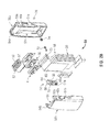
- FIG. 2A is a side, perspective view of the battery powered surgical instrument depicted in FIG. 1 separated from the battery assembly;
- FIG. 2B is an enlarged perspective view of the area of detail indicated in FIG. 2A with parts separated;
- FIG. 3 is a side view of the battery powered surgical instrument depicted in FIG. 1 separated from the battery assembly and rotated about a longitudinal axis "A-A";
- FIG. 4 is an end view of the battery powered surgical instrument depicted in FIG. 3 ;
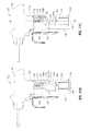
- FIGS. 5A and 5B are schematic views of a battery powered surgical instrument configured for use with a removable battery assembly according to another embodiment of the present disclosure
- FIGS. 6A-6C are schematic views of a battery powered surgical instrument configured for use with a removable battery assembly according to yet another embodiment of the present disclosure
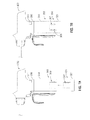
- FIGS. 7A-7B are schematic views of a battery powered surgical instrument configured for use with a removable battery assembly according to still another embodiment of the present disclosure
- FIGS. 8A and 8B are schematic views of a battery powered surgical instrument configured for use with a removable battery assembly according to still another embodiment of the present disclosure
- FIG. 9 is a schematic view of a battery powered surgical instrument configured for use with a removable battery assembly according to still another embodiment of the present disclosure.
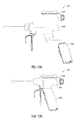
- FIGS. 10A-10B are schematic views of a battery powered surgical instrument configured for use with a removable battery assembly according to still another embodiment of the present disclosure
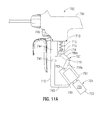
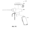
- FIGS. 11A-11C are schematic views of a battery powered surgical instrument configured for use with a removable battery assembly according to still another embodiment of the present disclosure
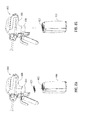
- FIGS. 12A-12D are schematic views of a battery powered surgical instrument configured for use with a removable battery assembly according to still another embodiment of the present disclosure.
- FIGS. 13A-13C are schematic views of a battery powered surgical instrument configured for use with a removable battery assembly according to still another embodiment of the present disclosure.
- proximal as is traditional, will refer to an end which is closer to the user, while the term “distal” will refer to an end that is farther from the user.
- Battery assembly 4 may be configured for use with a variety of battery powered instruments including, but not limited to, electrosurgical forceps, staplers, etc.
- the battery assembly 4 is described in terms of use with a portable ultrasonic surgical instrument 2 (instrument 2).
- Instrument 2 includes a housing 6 ( FIGS. 1 , 2A , 3 and 4 ) configured to house one or more components, e.g., transducer, generator and electrical circuitry that is configured for electrical communication with the battery assembly 4 of the instrument 2.
- a proximal end of housing 6 is configured to releasably couple to an ultrasonic generator 28 (generator 28) and the battery assembly 4, described in greater detail below.
- a distal end of the housing 6 is configured to support and/or couple to a shaft 8.
- Shaft 8 extends from housing 6 and defines a longitudinal axis "A-A" therethrough ( FIG. 1 ).
- a shaft rotation knob 26 ( FIG. 1 ) is operably coupled to the shaft 8 and is configured to rotate the shaft 8 in either direction about the longitudinal axis "A-A.”
- a proximal end 10 of the shaft 8 is operably coupled to the housing 6 and a distal end 12 of the shaft 8 is operably coupled to an end effector 14.
- the operation of parts of the end effector 14 e.g., jaw members 16 and 18
- the configuration of the end effector 14 may be altered to accommodate a specific electrosurgical procedure.
- the end effector may include an anvil and cartridge assembly; and if tissue is to be sealed, the end effector may include a pair of jaw members that are configured to grasp and subsequently seal tissue.
- one or more suitable energy forms may be utilized to seal the tissue, such as, for example, radio frequency energy, ultrasonic energy, etc.
- End effector 14 includes a pair of jaw members 16 and 18 ( FIGS. 1 and 2A ).
- end effector 14 includes jaw members 16 and 18 that are configured to treat tissue via ultrasonic energy.
- Jaw member 16 is pivotable about the jaw member 18 (and/or the distal end 12 of the shaft 8) and movable relative thereto when lever or movable handle 20 is moved proximally. More particularly, jaw member 16 is movable from an open position for positioning tissue between the jaw members 16 and 18, to a clamping position for grasping tissue between the jaw members 16 and 18 and against jaw member 18.
- jaw member 18 serves as an active or oscillating blade and is configured to treat tissue.
- jaw member 18 includes an ultrasonic member (not shown) that is operably coupled to a transducer 32 ( FIGS. 1 , 2A and 4 ), and an operating surface 22 ( FIGS. 1 and 2A ) configured to treat tissue.
- the operating surface 22 is configured to transect, dissect and/or coagulate tissue upon actuation of an activation button 24 ( FIGS. 1 , 2A and 3 ).
- Activation button 24 places the instrument 2 in two modes of operation, a low-power mode of operation and a high-power mode of operation. More particularly, activation button 24 is depressable to a first position for delivering low-power to the active jaw member 18 and a second position for delivering high-power to the active jaw member 18. In the first position, one or more audio or visual indicators may indicate to user that the activation button 24 is in the low-power mode. For example, and in one particular embodiment, an audio indicator may include a low-pitch, slow pulsating tone that indicates to a user that the activation button 24 is in the first position.
- one or more audio or visual indicators may indicate to user that the activation button is in the high-power mode, e.g., an audio indicator may include a high-pitch, fast pulsating tone that indicates to a user that the activation button 24 is in the second position.
- Generator 28 ( FIGS. 1 , 2A , 3 and 4 ) is configured to convert electrical energy generated by a battery 30 (as best seen in FIG. 2B ) of the battery assembly 4 to ultrasonic energy to drive the active jaw member 18.
- Generator 28 operably couples to the housing 6 and may be selectively removable therefrom either in connection with removal of the battery 30 or independently. More specifically in the embodiment shown in FIGS. 1 , 2A and 3 , to secure the generator 28 to the housing 6, a user positions the generator 28 on a top portion of the housing 6 at a proximal end thereof and turns a torquing knob 36 ( FIGS. 1 , 2A , 3 and 4 ) in a clockwise direction and hand tightens the generator 28 to the housing 6. In certain embodiments, a torque wrench (not shown) may be utilized to facilitate turning the torquing knob 36.
- Generator 28 includes transducer 32 (shown in phantom in FIGS. 1 , 2A and 4 ) that is configured to convert electrical energy to mechanical energy that produces motion at an end of a waveguide 34 (shown in phantom in FIG. 1 ) that is in operative communication with the active jaw member 18.
- the electronics of the generator 38 converts the electrical energy from the battery 30 into a high voltage AC waveform that drives the transducer 32.
- the frequency of this AC waveform is the same as the resonant frequency of the waveguide 34 and transducer 32.
- the magnitude of the AC waveform includes a value that produces the proper amount of mechanical motion.
- housing 6 includes a docking portion 40 (as best seen in FIGS. 2A and 3 ) defined therein.
- Docking portion 40 includes a generally elongated member 42 (see FIGS. 2A , 3 and 4 ) that extends in a generally perpendicular orientation with respect to a base member 44 and the longitudinal axis "A-A" (see FIGS. 2A , 3 and 4 ).
- the elongated member 42 includes one or more apertures 46 (see FIGS.
- Apertures 46 are disposed adjacent a bottom end of the elongated member 42 ( FIG. 2 ). Positioning the apertures 46 as such facilitates latching and unlatching of the battery assembly 4 from the housing 6.
- Base member 44 is configured to releasably engage the battery assembly 4 and includes a protrusion 52 of suitable configuration ( FIG. 3 ) operably disposed within and at a proximal end of the base member 44.
- the protrusion 52 is configured to releasably engage a corresponding pivot 54 that is disposed at a proximal end (or rear) of the handpiece 50 of the battery assembly 4 (as best seen in FIG. 4 ).
- Base member 44 includes electrical circuitry "EC" (see FIG. 3 , for example) therein that is utilized to provide communication between the generator 28 and the battery 30.
- battery assembly 4 is illustrated.
- the overall mechanical architecture of the battery assembly 4 includes handpiece 50 having battery 30 operably disposed therein, see FIG. 2B .
- handpiece 50 manufactured by any suitable manufacturing methods, may be made from any suitable material including, but not limited to plastic, plastic composites, metal, metal alloy, etc.
- the handpiece 50 includes a contact cap 56 configured to facilitate electrical communication between the contact cap 56 and the electrical circuitry "EC" associated with the base member 44.
- the contact cap 56 may be made from Bayer Makrolon® 2885 polycarbonate with a 20% glass fiber filler.
- handpiece 50 includes left and right clamshells 50a and 50b, respectively, that collectively define the handpiece 50 in the assembled configuration.
- the left and right clam shells 50a and 50b may be coupled together via one or more suitable coupling methods.
- the left and right clam shells are ultrasonically welded together.
- Other forms and/or methods, e.g., soldering, of coupling the left and right clamshells 50 and 50b, respectively, to one another are contemplated.
- the left and right clamshells 50a and 50b define an enclosure 51 that is configured to house battery assembly 30 including cells 58, printed circuit assemblies 60, and the contact cap 56.
- each of the left and right clam shells 50a and 50b includes a minimum wall thickness of 0.010 inches to about 0.080 inches.
- the wall thickness of the respective left and right clamshells 50a and 50b is about 0.060 inches.
- the size of enclosure 51 is defined by the left and right clamshells 50a and 50b, respectively, provides internal "free space” adjacent to the cells 58. This "free space” is designed to accommodate the increase in thickness of the cells 58 as a result of charge and discharge cycles over the life of the battery assembly 4. That is, the cells 58 are allowed to "swell" uninterrupted into the "free space".
- the handpiece 50 including the left and right clamshells 50a and 50b, respectively are also configured to maintain the contact cap 56 in a substantially fixed orientation.
- the left and right clamshells 50a and 50b collectively define the pivot 54 at a proximal end (or rear) of the handpiece 50 (see FIG. 4 ).
- the pivot 54 is configured to releasably engage the protrusion 52 on the base member 44 such that the battery assembly 4 may be removably engaged with the instrument 2 and/or a charger (not shown) in a specific orientation.
- the pivot 54 includes a notched area 67 that corresponds to the configuration of the protrusion 52 ( FIG. 4 ).
- Pivot 54 also includes a lip 69 that is configured to removably and pivotably engage the protrusion 52 ( FIGS. 3 and 4 ).
- Each of the left and right clamshells 50a and 50b includes one or more dimples or indents 53a and 53b ( FIGS. 2A and 2B ) that are configured to releasably mate with corresponding detents that are operably disposed on a charger (not shown) that is configured to charge the battery 30 of the battery assembly 4.
- Each of the left and right clamshells 50a and 50b includes respective protrusions 48a and 48b ( FIGS. 2A and 2B ) that are configured to releasably mate with the corresponding apertures 46 of the elongated member 42.
- the protrusions 48a and 48b are configured to remain engaged with the corresponding apertures 46 until a release latch 62 is moved into the extended position ( FIG. 2A illustrates with aid of directional arrows the latch 62 in the extended position phantomly).
- the release latch 62 is operably disposed at a distal end (or in the front of the handpiece 50).
- the release latch 62 may be made out of any suitable material hereinbefore described.
- the release latch 62 is made out of polypropylene including a 15% glass fiber filler. The polypropylene with a 15% glass fiber filler material prevents and/or eliminates the effects of parasitic welding to the handpiece 50 during the ultrasonic weld assembly of the left and right clamshells 50a and 50b, respectively.
- the release latch 62 provides a mechanism to remove the battery assembly 4 from the instrument 2.
- the release latch 62 is a "free-floating" part that is normally held in an “idle” or retracted position ( FIGS. 1 and 2A ) by the elongated member 42.
- the release latch 62 In order to "de-mate” or uncouple the battery assembly 4 from the instrument 2, the release latch 62 is moved in a generally upward direction to the "use" or extended position (shown in phantom in FIG. 2A ) that mechanically separates the battery assembly 4 and handpiece 50 from the instrument 2.
- a spring (not shown) may be utilized to bias the release latch 62 in the "idle” or retracted position.
- Release latch 62 includes a generally elongated configuration having a top portion 64 ( FIGS. 2A and 2B ) configured to contact an interior or proximal wall of the elongated member 42 when the release latch 62 is moved to the extended position.
- the top portion 64 includes a slanted or angled ramp portion 68 that is configured to be wedged between the interior wall of the elongated member 42 and the distal end of handpiece 50 adjacent the two protrusions 48 located on the handpiece 50 ( FIG. 2B ).
- the top portion 64 also includes an elongated lateral bar portion 70 ( FIG. 2B ) that is configured to inhibit or prevent movement of the release latch 62 past a predetermined point. More particularly, the lateral bar portion 70 is configured to contact the protrusions 48a and 48b when the release latch 62 is moved a predetermined distance to the extended position.
- Release latch 62 includes a bottom portion 66 ( FIGS. 2A and 2B ) that is ergonomically configured to receive a finger, e.g., a thumb, of a user.
- bottom portion 66 includes a generally ramp-like configuration at distal end thereof.
- Left and right sides 61a and 61b of the bottom portion 66 are slidably coupled to corresponding left and right flanges 51a and 51b that are operably disposed on the respective left and right clamshells 50a and 50b of the handpiece 50.
- the left and right sides 61a and 61b and corresponding left and right flanges 51a and 51b collectively allow a user to move the release latch 62 from the retracted position to the extended position (and vice versa) while keeping the release latch 62 attached to the handpiece 50.
- the contact cap 56 has metal electrical contacts insert molded to form a homogenized part.
- the contact cap 56 may be coupled or sealed to the handpiece 50 by any suitable coupling or sealing methods including, but not limited to soldering, welding, application of an adhesive, etc.
- the contact cap 56 is sealed to the handpiece 50 with a light cure potting adhesive.
- One or more ribs 57 and a frame 59 are operably disposed within the battery assembly 4 and are configured to collectively maintain the printed circuit assemblies 60 in a substantially fixed configuration when the left and right clam shells 50a and 50b are in the assembled configuration ( FIG. 2B ). More particularly, one or more ribs 57 are operably disposed on an underside of the cap 56 and frame 59 is operably disposed on a top portion of a sleeve 63 that is configured to house one or more cells (3 lithium polymer cells) of the battery 30.
- An over pressure safety vent 72 may be located on one or both of the left and right clamshells 50a and 50b.
- the over pressure safety vent or valve 72 is located on the left clam shell 50a.
- the over pressure safety valve 72 is secured to the left clamshell 50a via a spring 74 and an o-ring 76 ( FIG. 2B ).
- the spring 74 biases the over pressure safety valve 72 against the o-ring 76. Pressure is released through over pressure safety valve 72 once a predetermined pressure is reached and/or exceeded inside the handpiece 50.
- the battery assembly 4 is, initially, coupled to a charger (not shown).
- a user positions the pivot 54 adjacent the protrusion 52 and "swings" the distal end of the handpiece 50 toward the elongated member 42 of the docking portion 40.
- the protrusions 48a and 48b engage the apertures 46.
- the release latch 62 is in the retracted position ( FIGS. 1 and 2A ).
- a user moves the release latch 62 upward to the extended position (shown in phantom in FIG. 2A ). Upward movement of the release latch 62 causes the ramp portion 68 of the top portion 64 to be wedge between the interior wall of the elongated member 42, which, in turn, causes the protrusions 48a and 48b to disengage from the apertures 46.
- the unique configuration of the battery assembly 4 including the pivot 52, release latch 62 and protrusions 48a and 48b that releasably couple to the apertures 46 on the elongated member 42 of the docking portion 42 allows a user to conveniently and easily attach and detach the battery assembly 4 from the instrument 2.
- the instrument 2 and battery assembly 4 may be configured to releasably couple to one another via one or more alternate coupling methods.
- an alternate embodiment of a portable surgical the instrument is designated instrument 102.
- Instrument 102 is configured to releasably couple to a battery assembly 104.
- Instrument 102 and battery assembly 104 are substantially identical to instrument 2 and battery assembly 4. In view thereof, and so as not to obscure the present disclosure with redundant information, only those features that are unique to instrument 102 and battery assembly 104 are described herein.
- instrument 102 does not include a docking portion 40 having an elongated member 42. More particularly, instrument 102 includes a housing 106 having a base member 144 (shown partially separated from the housing 106) that includes one or more flexible arms or "claws" 103. For illustrative purposes, base member 144 is shown including 4 "claws" 103a-103d.
- Claws 103a-103d may be made from any suitable materials including, but not limited to metal, metal alloy, plastic, plastic composites, one of the aforementioned materials, etc. In the embodiment illustrated in FIGS. 5A and 5B , claws 103a-103d are made from metal.
- Claws 103a-103d are configured to releasably engage the battery assembly 104.
- claws 103a-103d are pivotably coupled to the base member 144 via one or more coupling methods, e.g., pivot pins or hinges not explicitly shown.
- the claws 103a-103d include respective bottom portions configured to engage a bottom portion of the battery assembly 104. More particularly, the claws 103a-103d include respective bottom portions 105a-105d each having a generally square shape.
- the claws 103a-103d When the claws 103a-103d are in the closed or engaged position, the claws 103a-103d collectively form a generally square-like shape, as best seen in FIG. 5B . In the engaged position the claws 103a-103d are configured to "lock" the battery assembly 104 in the engaged position.
- the claws 103a-103d may be configured to translate within the base member 144; this may facilitate maintaining the battery assembly 104 in the locked or engaged position and/or engaging the contact cap 56 of the battery assembly 104 with the electrical circuitry of the base member 144.
- battery assembly 104 does not include a release latch 62. More particularly, the battery assembly 104 is positionable between the claws 103a-103d and is configured to engage the base member 144 when the claws 103a-103d are moved to the closed or engaged position. In the closed or engaged position the battery assembly 104 communicates with the electrical circuitry disposed within the base member 144.
- claws 103a-103d are configured to mate with corresponding grooves or notches 106a-106d that are operably disposed on an exterior surface the battery assembly 104 ( FIG. 5A ).
- the claws 103a-103d are, initially, in the open position ( FIG. 5A ).
- a user positions the battery 104 between the claws 103a-103d.
- the claws 103a-103d engage the corresponding grooves 105a-105d.
- a user then moves the claws 103a-103d to the closed position ( FIG. 5B ).
- a user may, subsequently, move the claws 103a-103d upward and into the base member 144 to lock the battery assembly 104 into the claws 103a-103d.
- instrument 202 is configured to releasably couple to a battery assembly 204.
- Instrument 202 and battery assembly 204 are substantially identical to instrument 2 and battery assembly 4. In view thereof, and so as not to obscure the present disclosure with redundant information, only those features that are unique to instrument 202 and battery assembly 204 are described herein.
- a lock 203 in the form of a guide rail 205 is operably disposed within base member 244 of a housing 206 of the instrument 202 ( FIGS. 6A-6C ). More particularly, the guide rail 205 is configured to releasably engage a corresponding groove 207 ( FIGS. 6A-6C ) defined along a periphery of a lock bolt 209 ( FIGS. 6A-6C ) that is coupled to the battery assembly 204.
- the guide rail 205 may be formed from any materials described hereinbefore, e.g., plastic.
- the guide rail 205 may include any suitable configuration. In the illustrated embodiment, the guide rail includes a generally helical configuration having a diameter that is configured to receive the lock bolt 209 therethrough (see FIGS. 6B-6C ).
- a knob 211 ( FIGS. 6A-6C ) is operably coupled to the battery 204 and is rotatable with respect thereto in a clockwise and counterclockwise direction.
- the knob 211 is configured to turn the lock bolt 209 such that the lock bolt 209 either engages or disengages the guide rail 205.
- the knob 211 is turned a 1 ⁇ 4 of a full turn in either the clockwise or counterclockwise direction to engage or disengage the lock bolt 209 to and from the guide rail 205, respectively.
- a threaded rod 213 extends through the length of the battery assembly 204 and is configured to operably couple the lock bolt 209 to the knob 211. More particularly, the threaded rod 213 extends the length of the battery assembly 204 and couples thereto via a lock nut 215 that is disposed adjacent the knob 211 ( FIGS. 6A-6C ). The lock nut 215 is configured to facilitate turning the lock bolt 209 while maintaining engagement of the threaded rod 213 to the battery assembly 204.
- the battery assembly 204 is, initially, coupled to a charger (not shown).
- a user positions the lock bolt 209 within the guide rail 205 and turns the knob 211 a 1 ⁇ 4 turn in the clockwise direction, which, in turn, rotates the lock bolt 209 such that the lock bolt 209 engages the guide rail 205 ( FIG. 6C ).
- a user turns the knob 211 a 1 ⁇ 4 turn in the counter clockwise direction, which, in turn, rotates the lock bolt 209 such that the lock bolt 209 disengages the guide rail 205 ( FIG. 6B ).
- instrument 302 which is configured to releasably couple to a battery assembly 304.
- Instrument 302 and battery assembly 304 are substantially identical to instrument 2 and battery assembly 4. In view thereof, and so as not to obscure the present disclosure with redundant information, only those features that are unique to instrument 302 and battery assembly 304 are described herein.
- the battery assembly 304 magnetically couples to a base member 344 of a housing 306 via a magnetic mechanism 305 that is operably associated with each of the battery assembly 304 and the base member 344.
- the magnetic mechanism 305 includes one or more magnets 307 (or magnetic materials) on the battery assembly 304 and one or more magnets 309 (or magnetic materials) on or within the base member 344.
- the magnets 309 are shown within the base member 344.
- the magnets 307 and 309 on the respective battery assembly 304 and the base member 344 have opposite polarities.
- one or both of the magnets 307 and 309 is/are an electromagnet that is capable of changing polarities.
- the magnet 309 within the base member 344 is illustrated as the electromagnet.
- An actuator 311 ( FIGS. 7A and 7B ) is operably disposed on the instrument 302 and is in operative communication with the magnet 309.
- the actuator 311 is configured to change a polarity of magnet 309 for locking and unlocking the battery assembly 304 to and from the instrument 302.
- the battery assembly 304 includes a flanged bottom portion 321.
- the flanged bottom portion 321 provides a gripping surface for a user.
- the battery assembly 304 is, initially, coupled to a charger (not shown).
- a user positions the battery assembly 304 into the base member 344.
- the opposite polarities of the magnets 307 and 309 maintain the battery assembly 304 and instrument 302 in the engaged or locked position ( FIG. 7B ).
- a user presses the actuator 311 to change the polarity of the magnet 309 to an opposite polarity of the magnet 307, which, in turn, allows the user to remove the battery assembly 304 from the base member 344.
- the magnetic mechanism 305 may be configured such that a user may simply "pry" the magnets 307 and 309 apart as needed. That is, the magnets 307 and 309 may be configured to maintain the battery assembly 304 and the instrument 302 in an engaged or locked position until a predetermined amount of force, i.e., a force greater than the magnet force coupling the battery assembly 304 to the instrument 302, is applied to the battery assembly 304 and/or instrument 302.
- a predetermined amount of force i.e., a force greater than the magnet force coupling the battery assembly 304 to the instrument 302
- Instrument 402 and battery assembly 404 are substantially identical to instrument 2 and battery assembly 4. In view thereof, and so as not to obscure the present disclosure with redundant information, only those features that are unique to instrument 402 and battery assembly 404 are described herein.
- An adhesive is operably coupled to either a battery assembly 404 or a base member 444 of a housing 406.
- the adhesive is configured to couple the battery assembly 404 including the battery 30 to a housing 406.
- the adhesive is a low tack adhesive, such as, for example, a low tack adhesive tape 421.
- the low tack adhesive tape 421 is operably disposed adjacent a contact cap 460 of the battery assembly 404 and includes a grid-like configuration similar to that of the contact cap 460. More particularly, the low tack adhesive tape 421 is fixedly coupled to the battery assembly 404 and substantially surrounds the grid of the contact cap 460.
- the low tack adhesive tape 421 is configured to stick to an internal surface of the base member 444.
- the low tack adhesive tape 421 is configured to stick to an internal area of the base member 444 adjacent the electrical circuitry "EC" contained therein.
- the low tack adhesive tape 421 is configured to stick to the internal area of the base member in a manner that does not interfere with the operation of the electrically circuitry "EC.”
- a removable film covers or protects the low tack adhesive tape 421 when the battery assembly 404 is not coupled to the instrument 402. Accordingly, the "tackiness" of the low tack adhesive tape 421 is not compromised when the battery assembly 404 is not coupled to the instrument 402 and ensures that the low tack adhesive tape 421 provides the required amount of "tackiness” and/or “sticking" power.
- a user removes the film from the low tack adhesive tape 421 and positions the battery assembly 404 within the base member 444 of the instrument 402.
- a user simply "pries” or pulls the battery assembly 404 from the base member 444.
- Instrument 502 and battery assembly 504 are substantially identical to instrument 2 and battery assembly 4. In view thereof, and so as not to obscure the present disclosure with redundant information, only those features that are unique to instrument 502 and battery assembly 504 are described herein.
- the battery assembly 504 remotely attaches to a housing 506 of the instrument 502 via one or more suitable coupling methods including, but not limited to a wire, cable, cord, USB, etc.
- a cable 507 provides electrical communication between the instrument 502 and battery assembly 504.
- the housing 506 includes a port 508 thereon that is configured to connect to an end of the cable 507.
- a port 511 is disposed on the battery assembly 504 and is configured to receive an end of the cable 507.
- the battery assembly 504 is configured to removably attach to an arm of a user.
- a holding device or harness 509 is configured to removably attach to an arm of a user and configured to house the battery assembly 504 therein.
- One or more straps may be coupled to the harness 509 and utilized to attach the harness 509 to the arm of a user.
- two straps fitted with Velcro ® may be utilized to secure the harness 509 to an arm of a user.
- the cable 507 is coupled to each of the ports 511 and 508 on the battery assembly 504 and the housing 506, respectively. Subsequently, the battery assembly 504 is positioned on or attached to the harness 509 that is attached to a user. To uncouple the battery assembly 504 from the instrument 2, a user simply removes the cable from the port 511 and/or the port 508 of the respective battery assembly 504 and instrument 502.
- the battery assembly 504 may be simply positioned adjacent or in the vicinity, e.g., on the operating table, of the instrument 502.
- the exact positioning of the battery assembly 504 with respect to the instrument 502 may depend on the length of the cable 507 provided, the surgical procedure, etc.
- Instrument 602 and battery assembly 604 are substantially identical to instrument 2 and battery assembly 4 and only those features that are unique to instrument 602 and battery assembly 604 are described herein.
- a housing 606 includes a docking member 640 that is made from an elastomeric material, such as, for example, polychloroprene.
- the docking member 640 includes an elongated configuration with a generally oval shape having an open sidewall 642 defined therein that is configured to receive and releasably house the battery assembly 604 therein.
- the battery assembly 604 may include a length that is slightly larger than a length of the docking member 640.
- the docking member 640 exerts an upward force on the battery assembly 604 such that the contact cap 56 contacts and remains in electrical communication with the electrical circuitry "EC" contained within the base member 644.
- the battery assembly 604 In use, to couple the battery assembly 604 to the instrument 602, the battery assembly 604 is positioned within the docking member 640. To remove the battery assembly 604 from the docking member 640, a user grasps the battery assembly 604 and "pries" or pulls the battery assembly 604 therefrom.
- Instrument 702 and battery assembly 704 are substantially identical to instrument 2 and battery assembly 4 and only those features that are unique to instrument 702 and battery assembly 704 are described herein.
- a docking portion 740 ( FIG. 11A ) includes an elongated member 742 that is disposed generally perpendicularly with respect to the longitudinal axis "A-A" and a bottom portion 743 that is configured to engage a corresponding bottom portion of a handpiece 750 of the battery assembly 704.
- a release mechanism 741 is operably disposed on the elongated member 742 of the docking portion 740 and is configured to disengage the handpiece 750 including a battery 730 of the battery assembly 704 from the docking portion 740. More particularly, the release mechanism 741 is translatable along the longitudinal axis "A-A" and is configured to "push" the battery assembly 704 proximally and out of a locked position and/or engagement with the docking portion 740 when release mechanism 741 is actuated.
- a spring (not shown) may be operably coupled to the release mechanism 741 and may be configured to bias the release mechanism 741 in an initial position, e.g., a non-actuated position.
- a linkage system in the form of an over-center linkage mechanism 707 is operably disposed in base member 744 of the docking portion 740.
- the linkage system 707 includes one or more over-center links that pivot about another.
- two (2) over-center links 709a and 709b are shown pivotable about one another.
- Link 709b is operably coupled to a biasing member 712 for biasing the links 709a, 709b in locked configuration in the docking portion 740, see FIG. 11C , for example.
- Links 709a, 709b are configured to selectively engage either the handpiece 750 or the battery 730.
- the link 709a couples via a pivot pin 752 to a housing 751 that is shaped to complement the handpiece 750 (or the battery 730) of the battery assembly 704 ( FIGS. 11A-11C ).
- the pivot pin 752 allows the battery assembly 704 to pivot about the link 709a when the battery assembly 704 is being “loaded" into the docking portion 740 ( FIGS. 11A-11B ).
- Housing 751 is configured to communicate with the electrical circuitry in the housing 706 such that when the battery assembly 704 is coupled to the housing 751, the battery 704 is capable of providing electrical energy to the generator 28.
- the link 709a pivotably couples to link 709b via one or more suitable coupling methods.
- a pivot pin 719 is operably disposed at a bottom end of the link 709b and operably couples to an aperture 720 (shown engaged with the pivot pin 719 and as such not explicitly shown) disposed at a top end of the link 709a.
- Link 709b includes a generally elongated configuration having a piston head 713 of suitable configuration operably coupled at a top end thereof ( FIGS. 11A-11C ) via a pivot pin 714.
- the piston head 713 includes a generally cylindrical configuration having a top surface thereof operably coupled to the biasing member 712 by one or more suitable coupling methods, e.g., soldering.
- the biasing member 712 may be any suitable biasing member including a spring, resilient member, etc.
- the biasing member 712 is in the form of a compression spring that is operably disposed within an elongated or longitudinal cavity or slot 715 of the base member 744.
- the biasing member 712 including the piston head 713 of the link 709b is configured to translate within the longitudinal slot 715. More particularly, the biasing member 712 including the piston head 713 is configured to translate from an normally extended position that corresponds to the link 709a being in the unlocked position ( FIG. 11A ), to a retracted position that corresponds to the link 709a being coupled to the battery assembly 704 and in the locked position ( FIG. 11C ).
- the link 709a in the locked position, the link 709a will be disposed past a center-line "CL" ( FIG. 11C ).
- the link 709a is configured to remain in the locked position under the biasing force provided by the spring 712 until a user actuates the release mechanism 741.
- a user loads the battery assembly 704 into the housing 751. Then, a user pivots the housing 751 and positions the housing 751 including the battery assembly 704 therein into the docking portion 740 ( FIG. 11B ). To lock the housing 751 into the docking portion 740, a user pushes the links 709a, 709b distally toward the docking portion 740 ( FIG. 11B ).
- the links 709a, 709b transition past vertical, e.g., "over-center,” and past the "CL" to the locked position that corresponds to the battery assembly 704 being latched or coupled to the docking portion 740 of the instrument 702 ( FIG. 11C ).
- a user may move the release mechanism 741 proximally to push the battery assembly 704 out of the locked position and/or engagement with the docking portion 740.
- Instrument 802 is configured to releasably couple to a battery assembly 804.
- Instrument 802 and battery assembly 804 are substantially identical to instrument 2 and battery assembly 4 and only those features that are unique to instrument 802 and battery assembly 804 are described herein.
- a bottom portion of the battery assembly 804 includes one or more latching members 803.
- the latching members 803 include two protrusions or detents 803a and 803b that are configured to releasably engage two corresponding apertures or indents 804a and 804b that are operably disposed on a bottom portion 843 of a docking portion 840.
- a release mechanism 841 (shown in phantom in the representative figures) is disposed on an elongated member 842 of the docking portion 840 and is configured to disengage the detents 803a and 803b from the indents 804a and 804b of the docking portion 840.
- the release mechanism 841 may be any suitable release mechanism such as, for example, a slide lever, push-button or the like. In the embodiment illustrated in FIGS. 12A, 12B and 12D , the release mechanism 841 is in the form of a slide lever.
- Release mechanism 841 is translatable along the longitudinal axis "A-A” and is configured to "push” the battery assembly 804 out of a locked position and/or engagement with the docking portion 840 when release mechanism 841 is actuated.
- a spring (not shown) may be operably coupled to the release mechanism 841 and configured to bias the release mechanism 841 in an initial position, e.g., a non-actuated position.
- the docking portion 840 may be configured for rear loading ( FIGS. 12A and 12B ) or, in certain embodiments, front loading, see FIG. 12D for example.
- a user positions the battery assembly 804 into the docking portion 840 of the instrument 2 such that the detents 803a and 803b engage the corresponding indents 804a and 804b. Engagement of the detents 803a and 803b with the corresponding indents 804a and 804b secures and/or locks the battery assembly 804 to the instrument 802 ( FIG. 12B ).
- a user moves the release mechanism 841 either distally ( FIG. 12A ) or proximally ( FIG. 12D ); this of course will depend on if the instrument 802 is configured for rear or front loading, respectively.
- the bottom portion 843 of the docking portion 840 may be pivotably coupled to the elongated member 842 (see FIG. 12C for example).
- a hinge 850 of suitable configuration may operably couple the elongated member 842 to the bottom portion 843.
- the hinge 850 is movable from an unlatched position ( FIG. 12C ) for loading the battery assembly 804 to the docking portion 840, to a latched position (not shown) for locking the battery assembly to docking portion 840.
- FIG. 12C unlatched position
- one or more detents may be configured to releasably couple to one or more corresponding indents, e.g., indent 804a.
- detent 803a may be configured to releasably couple to one or more corresponding indents, e.g., indent 804a.
- indent 804a may be configured to releasably couple to one or more corresponding indents, e.g., indent 804a.
- Each of the detents and indents 803a and 804a function as previously described.
- the instrument 802 may be configured to operably couple to a remote suction device, such as, for example, a hospital suction source, see FIG. 12D for example.
- a remote suction device such as, for example, a hospital suction source, see FIG. 12D for example.
- a lumen 817 illustrated in phantom in FIG.
- 12D extends through the housing 806 and may be in fluid communication with the hospital suction source via a proximal end that is configured to couple to the remote suction source, e.g., via a proximal port 818a, and a distal end that is configured to draw the battery assembly 804 into the docking portion 840, e.g., via a distal port 818b.
- the remote suction source e.g., the suction provided by the hospital suction source, helps draw the battery assembly 804 into the docking portion 804 and helps maintain a secured and/or fixed relationship between the battery assembly 804 and in the instrument 802.
- an embodiment of a portable surgical instrument is designated instrument 902.
- Instrument 902 is configured to releasably couple to a battery assembly 904.
- Instrument 902 and battery assembly 904 are substantially identical to instrument 2 and battery assembly 4 and only those features that are unique to instrument 902 and battery assembly 804 are described herein.
- the instrument 902 includes a selectively removable universal housing 906 that is configured to couple to the instrument 902 via one or more suitable coupling methods, e.g., snap-fit, press-fit, indent/detent configuration, etc.
- suitable coupling methods e.g., snap-fit, press-fit, indent/detent configuration, etc.
- Removable housing 906 is configured to couple to a generator 928 (or other suitable device) and a battery assembly 904 in a manner as described hereinbefore.
- the universal housing 906 is configured to accommodate various configurations of battery assemblies, as well, as various configurations of generators 928.
- housing 906, battery assembly 904 and generator 928 may, initially, be coupled to one another, see FIG. 13A .
- a user may couple the housing 906 including the battery assembly 904 and generator 928 coupled thereto to the instrument 902, see FIG. 13B .
- the generator 928 and/or the battery assembly 904 may be uncoupled from the housing 902 in a manner as herein described before, see FIG. 13C .
- the unique configuration of the housing 906 allows a user to couple different generators and/or difference battery assemblies to the instrument 902.
- a user may couple a first generator that is configured to produce a specific tissue effect, e.g., either transect, dissect, seal and coagulate tissue, and then couple a different, second generator that is configured to produce a tissue effect that is different than the first tissue effect, e.g., either transect, dissect, seal and coagulate.
- the instrument 2 may be configured to electrosurgically treat tissue via RF energy.
- the generator 28 is configured to generate RF energy.
- the transducer and waveguide will be replaced by one or more electrical feeds that are in electrical communication with the jaw members 16, 18 and configured to provide RF energy thereto to electrosurgically treat tissue.
- the instrument 2 may be configured to staple tissue.
- the generator 28 is configured to generate electrical energy and the jaw members 16, 18 will be replaced by an anvil assembly and a cartridge assembly (not explicitly shown).
- One or more electrical feeds that are in electrical communication with the anvil assembly and cartridge assembly are configured to provide electrical energy thereto to energize the staples in the cartridge assembly prior to ejection thereof.
- the staples may be energized as they are being formed, e.g., electrical energy is applied to an anvil plate of the anvil assembly to energize the staples.
Landscapes
- Health & Medical Sciences (AREA)
- Engineering & Computer Science (AREA)
- Life Sciences & Earth Sciences (AREA)
- Surgery (AREA)
- Public Health (AREA)
- General Health & Medical Sciences (AREA)
- Veterinary Medicine (AREA)
- Animal Behavior & Ethology (AREA)
- Nuclear Medicine, Radiotherapy & Molecular Imaging (AREA)
- Molecular Biology (AREA)
- Medical Informatics (AREA)
- Heart & Thoracic Surgery (AREA)
- Biomedical Technology (AREA)
- Otolaryngology (AREA)
- Physics & Mathematics (AREA)
- Plasma & Fusion (AREA)
- Chemical Kinetics & Catalysis (AREA)
- Electrochemistry (AREA)
- General Chemical & Material Sciences (AREA)
- Chemical & Material Sciences (AREA)
- Battery Mounting, Suspending (AREA)
- Surgical Instruments (AREA)
- Dentistry (AREA)
- Mechanical Engineering (AREA)
Abstract
A surgical instrument is provided and includes a housing including an elongated shaft. The housing includes a docking portion that includes one or more apertures defined therein and electrical circuitry disposed therein. An end effector is operably supported at a distal end of the elongated shaft. A battery assembly is selectively and pivotably engageable with the docking portion of the housing and configured to generate electrical energy. The battery assembly includes one or more protrusions that are configured to releasably engage the aperture(s) on the docking portion and a latch mechanism that is movable from an initial position for latching the battery assembly to the docking portion to a subsequent position for unlatching the battery assembly from the docking portion. The battery assembly is adapted to communicate with the electrical circuitry of the docking member upon insertion of the battery assembly into the at least one aperture.
Description
- The present disclosure relates to portable surgical instruments and, more particularly, to portable surgical instruments that utilize a handpiece configured to house a battery and/or battery assembly and releasably couple to the portable surgical instrument.
- Portable surgical instruments are known in the medical arts. Portable surgical instruments overcome some of the drawbacks that are typically associated with surgical instruments that draw power from electrical outlets. That is, outlet driven surgical instruments utilize power cords that may create tripping and/or entanglement hazards in an operating room environment.
- Typically, the portable surgical instrument includes a battery or battery assembly that is configured to removably couple or "latch" to the portable surgical instrument. In an ideal scenario, the battery or battery assembly remains coupled or "latched" to the portable surgical instrument during the entirety of the surgical procedure. Unfortunately, and in certain instances, the battery or battery assembly sometimes has to be uncoupled or "unlatched" from the portable surgical instrument during the surgical procedure. For example, the battery or battery assembly may have to be unlatched from the surgical instrument for sterilization (or re-sterilization), charging (or recharging), etc.
- As can be appreciated, removable batteries or battery assemblies that are configured to quickly and easily couple or latch to a handpiece of the portable surgical instrument may prove advantageous in the surgical environment.
- As it is used herein, "electrosurgical procedure" generally refers to any electrosurgical procedure involving any form of energy, such as, for example, microwave energy, radiofrequency (RF) energy, ultrasonic energy, thermal energy, etc. As it is used herein, "end effector" generally refers to an end effector that is capable of treating tissue, such as, for example, end effectors that include jaw members configured to treat tissue utilizing ultrasonic energy, electrosurgical energy (e.g., radio frequency energy and/or microwave energy), and/or thermal energy; and electrosurgical stapler end effectors, e.g., anvil/cartridge assemblies, that are configured to staple and, subsequently, electrosurgically treat tissue utilizing one of the aforementioned energies.
- An aspect of the present disclosure provides a surgical instrument. The surgical instrument includes a housing that includes an elongated shaft extending distally therefrom having a longitudinal axis defined therethrough. The housing includes a docking portion including one or more apertures defined therein and electrical circuitry disposed therein. An end effector is operably supported at a distal end of the elongated shaft. A battery assembly selectively and pivotably engageable to the docking portion of the housing is configured to generate electrical energy. The battery assembly includes one or more protrusions that are configured to releasably engage the aperture(s) on the docking portion and a latch mechanism that is movable from an initial position for latching the battery assembly to the docking portion to a subsequent position for unlatching the battery assembly from the docking portion. The battery assembly may be adapted to communicate with the electrical circuitry of the docking member upon insertion of the battery assembly into the at least one aperture defined in the docking portion.
- A selectively removable generator may be in operative communication with the battery assembly via the electrical circuitry of the docking member.
- The battery assembly may include a pivot member that is configured to pivot about a corresponding member disposed on the housing of the ultrasonic surgical instrument. In this instance, the pivot member may include a generally hook shape and may be disposed at a proximal end of the battery assembly.
- The corresponding protrusions disposed on the battery assembly may be located at a distal end thereof.
- In certain instance, the aperture(s) on the docking portion is further defined by two or more apertures and the protrusion(s) on the battery assembly is further defined by two or more protrusions that are configured to engage the at least two apertures.
- The latch may be normally held in a retracted position by an elongated member of the docking portion. Moreover, a top portion of the latch may include a lateral bar portion that is configured to contact the protrusion(s) on the battery assembly to prevent movement of the latch past a predetermined point. Further, the latch may include a bottom portion that is ergonomically configured to receive a finger of a user.
- In certain instances, the battery assembly may include an over pressure safety vent.
- The end effector may include a clamping jaw member that is movable in relation to an active jaw member between an open position spaced from an operating surface of the active jaw member and a closed position in juxtaposed alignment with the operating surface of the active jaw member. Moreover, the housing may include a jaw lever for imparting movement of the clamping jaw. Further, the operating surface may be configured to one of transect, dissect, seal and coagulate tissue.
- An aspect of the present disclosure provides a surgical system for treating tissue. The surgical instrument includes a housing that includes an elongated shaft extending distally therefrom having a longitudinal axis defined therethrough. The housing includes a docking portion including one or more apertures defined therein and electrical circuitry disposed therein. An end effector is operably supported at a distal end of the elongated shaft. A battery assembly selectively and pivotably engageable to the docking portion of the housing is configured to generate electrical energy. The battery assembly includes one or more protrusions that are configured to releasably engage the aperture(s) on the docking portion and a latch mechanism that is movable from an initial position for latching the battery assembly to the docking portion to a subsequent position for unlatching the battery assembly from the docking portion. A selectively removable generator is in operative communication with the battery assembly via the electrical circuitry of the docking member.
- The battery assembly may include a pivot member that is configured to pivot about a corresponding member disposed on the housing of the ultrasonic surgical instrument. In this instance, the pivot member may include a generally hook shape and may be disposed at a proximal end of the battery assembly.
- The corresponding protrusions disposed on the battery assembly may be located at a distal end thereof.
- In certain instance, the aperture(s) on the docking portion is further defined by two or more apertures and the protrusion(s) on the battery assembly is further defined by two or more protrusions that are configured to engage the at least two apertures.
- The latch may be normally held in a retracted position by an elongated member of the docking portion. Moreover, a top portion of the latch may include a lateral bar portion that is configured to contact the protrusion(s) on the battery assembly to prevent movement of the latch past a predetermined point.
- An aspect of the present disclosure also provides a method of providing electrical energy to a surgical instrument. A surgical instrument that includes a housing including a docking portion having one or more apertures defined therein and electrical circuitry disposed therein is provided. A battery assembly is pivotably engaged into the at least one aperture defined in the docking portion of the surgical instrument. The battery assembly includes one or more protrusions that releasably engage the aperture(s) on the docking portion and a latch mechanism that is movable from an initial position for latching the battery assembly to the docking portion to a subsequent position for unlatching the battery assembly from the docking portion. The battery assembly is caused to communicate with the electrical circuitry of the docking member upon pivotable engagement of the battery assembly into the at least one aperture defined in the docking portion.
- Embodiments of the presently disclosed specimen retrieval apparatus are described hereinbelow with reference to the drawings wherein:
-
FIG. 1 is a side, perspective view of a battery powered surgical instrument configured for use with a removable battery assembly according to an embodiment of the present disclosure; -
FIG. 2A is a side, perspective view of the battery powered surgical instrument depicted inFIG. 1 separated from the battery assembly; -
FIG. 2B is an enlarged perspective view of the area of detail indicated inFIG. 2A with parts separated; -
FIG. 3 is a side view of the battery powered surgical instrument depicted inFIG. 1 separated from the battery assembly and rotated about a longitudinal axis "A-A"; -
FIG. 4 is an end view of the battery powered surgical instrument depicted inFIG. 3 ; -
FIGS. 5A and 5B are schematic views of a battery powered surgical instrument configured for use with a removable battery assembly according to another embodiment of the present disclosure; -
FIGS. 6A-6C are schematic views of a battery powered surgical instrument configured for use with a removable battery assembly according to yet another embodiment of the present disclosure; -
FIGS. 7A-7B are schematic views of a battery powered surgical instrument configured for use with a removable battery assembly according to still another embodiment of the present disclosure; -
FIGS. 8A and 8B are schematic views of a battery powered surgical instrument configured for use with a removable battery assembly according to still another embodiment of the present disclosure; -
FIG. 9 is a schematic view of a battery powered surgical instrument configured for use with a removable battery assembly according to still another embodiment of the present disclosure; -
FIGS. 10A-10B are schematic views of a battery powered surgical instrument configured for use with a removable battery assembly according to still another embodiment of the present disclosure; -
FIGS. 11A-11C are schematic views of a battery powered surgical instrument configured for use with a removable battery assembly according to still another embodiment of the present disclosure; -
FIGS. 12A-12D are schematic views of a battery powered surgical instrument configured for use with a removable battery assembly according to still another embodiment of the present disclosure; and -
FIGS. 13A-13C are schematic views of a battery powered surgical instrument configured for use with a removable battery assembly according to still another embodiment of the present disclosure. - Detailed embodiments of the present disclosure are disclosed herein; however, the disclosed embodiments are merely examples of the disclosure, which may be embodied in various forms. Therefore, specific structural and functional details disclosed herein are not to be interpreted as limiting, but merely as a basis for the claims and as a representative basis for teaching one skilled in the art to variously employ the present disclosure in virtually any appropriately detailed structure.
- In the drawings and in the descriptions that follow, the term "proximal," as is traditional, will refer to an end which is closer to the user, while the term "distal" will refer to an end that is farther from the user.
- With reference to
FIGS. 1-4 , and initially with reference toFIG. 1 , a battery poweredsurgical instrument 2 configured for use with aremovable battery assembly 4 according to an embodiment of the present disclosure is illustrated.Battery assembly 4 may be configured for use with a variety of battery powered instruments including, but not limited to, electrosurgical forceps, staplers, etc. For illustrative purposes, thebattery assembly 4 is described in terms of use with a portable ultrasonic surgical instrument 2 (instrument 2). -
Instrument 2 includes a housing 6 (FIGS. 1 ,2A ,3 and4 ) configured to house one or more components, e.g., transducer, generator and electrical circuitry that is configured for electrical communication with thebattery assembly 4 of theinstrument 2. A proximal end ofhousing 6 is configured to releasably couple to an ultrasonic generator 28 (generator 28) and thebattery assembly 4, described in greater detail below. A distal end of thehousing 6 is configured to support and/or couple to ashaft 8. -
Shaft 8 extends fromhousing 6 and defines a longitudinal axis "A-A" therethrough (FIG. 1 ). A shaft rotation knob 26 (FIG. 1 ) is operably coupled to theshaft 8 and is configured to rotate theshaft 8 in either direction about the longitudinal axis "A-A." Aproximal end 10 of theshaft 8 is operably coupled to thehousing 6 and adistal end 12 of theshaft 8 is operably coupled to anend effector 14. The operation of parts of the end effector 14 (e.g.,jaw members 16 and 18) are movable relative to one another upon actuation ofhandle 20 coupled tohousing 6 as described in more detail below. - As can be appreciated, the configuration of the
end effector 14 may be altered to accommodate a specific electrosurgical procedure. For example, if tissue is to be stapled, the end effector may include an anvil and cartridge assembly; and if tissue is to be sealed, the end effector may include a pair of jaw members that are configured to grasp and subsequently seal tissue. In the latter instance, one or more suitable energy forms may be utilized to seal the tissue, such as, for example, radio frequency energy, ultrasonic energy, etc. -
End effector 14 includes a pair ofjaw members 16 and 18 (FIGS. 1 and2A ). For illustrative purposes,end effector 14 includesjaw members Jaw member 16 is pivotable about the jaw member 18 (and/or thedistal end 12 of the shaft 8) and movable relative thereto when lever ormovable handle 20 is moved proximally. More particularly,jaw member 16 is movable from an open position for positioning tissue between thejaw members jaw members jaw member 18. In the illustrated embodiment,jaw member 18 serves as an active or oscillating blade and is configured to treat tissue. To this end,jaw member 18 includes an ultrasonic member (not shown) that is operably coupled to a transducer 32 (FIGS. 1 ,2A and4 ), and an operating surface 22 (FIGS. 1 and2A ) configured to treat tissue. In the illustrated embodiment, the operatingsurface 22 is configured to transect, dissect and/or coagulate tissue upon actuation of an activation button 24 (FIGS. 1 ,2A and3 ). -
Activation button 24 places theinstrument 2 in two modes of operation, a low-power mode of operation and a high-power mode of operation. More particularly,activation button 24 is depressable to a first position for delivering low-power to theactive jaw member 18 and a second position for delivering high-power to theactive jaw member 18. In the first position, one or more audio or visual indicators may indicate to user that theactivation button 24 is in the low-power mode. For example, and in one particular embodiment, an audio indicator may include a low-pitch, slow pulsating tone that indicates to a user that theactivation button 24 is in the first position. Likewise, one or more audio or visual indicators (nor shown) may indicate to user that the activation button is in the high-power mode, e.g., an audio indicator may include a high-pitch, fast pulsating tone that indicates to a user that theactivation button 24 is in the second position. - Generator 28 (
FIGS. 1 ,2A ,3 and4 ) is configured to convert electrical energy generated by a battery 30 (as best seen inFIG. 2B ) of thebattery assembly 4 to ultrasonic energy to drive theactive jaw member 18. -
Generator 28 operably couples to thehousing 6 and may be selectively removable therefrom either in connection with removal of thebattery 30 or independently. More specifically in the embodiment shown inFIGS. 1 ,2A and3 , to secure thegenerator 28 to thehousing 6, a user positions thegenerator 28 on a top portion of thehousing 6 at a proximal end thereof and turns a torquing knob 36 (FIGS. 1 ,2A ,3 and4 ) in a clockwise direction and hand tightens thegenerator 28 to thehousing 6. In certain embodiments, a torque wrench (not shown) may be utilized to facilitate turning the torquingknob 36. -
Generator 28 includes transducer 32 (shown in phantom inFIGS. 1 ,2A and4 ) that is configured to convert electrical energy to mechanical energy that produces motion at an end of a waveguide 34 (shown in phantom inFIG. 1 ) that is in operative communication with theactive jaw member 18. When thetransducer 32 andwaveguide 34 are driven at their resonant frequency, they produce mechanical motion at theactive jaw member 18. The electronics of the generator 38 converts the electrical energy from thebattery 30 into a high voltage AC waveform that drives thetransducer 32. In one particular embodiment, the frequency of this AC waveform is the same as the resonant frequency of thewaveguide 34 andtransducer 32. As can be appreciated, the magnitude of the AC waveform includes a value that produces the proper amount of mechanical motion. - With reference again to
FIG.1 ,battery assembly 4 is configured to releasably couple to thehousing 6. To this end,housing 6 includes a docking portion 40 (as best seen inFIGS. 2A and3 ) defined therein.Docking portion 40 includes a generally elongated member 42 (seeFIGS. 2A ,3 and4 ) that extends in a generally perpendicular orientation with respect to abase member 44 and the longitudinal axis "A-A" (seeFIGS. 2A ,3 and4 ). Theelongated member 42 includes one or more apertures 46 (seeFIGS. 2A ,3 and4 ) that are configured to releasably engage one or morecorresponding protrusions FIG. 1 in combination withFIGS. 2A-3 ) of thebattery assembly 4.Apertures 46 are disposed adjacent a bottom end of the elongated member 42 (FIG. 2 ). Positioning theapertures 46 as such facilitates latching and unlatching of thebattery assembly 4 from thehousing 6. -
Base member 44 is configured to releasably engage thebattery assembly 4 and includes aprotrusion 52 of suitable configuration (FIG. 3 ) operably disposed within and at a proximal end of thebase member 44. Theprotrusion 52 is configured to releasably engage acorresponding pivot 54 that is disposed at a proximal end (or rear) of thehandpiece 50 of the battery assembly 4 (as best seen inFIG. 4 ).Base member 44 includes electrical circuitry "EC" (seeFIG. 3 , for example) therein that is utilized to provide communication between thegenerator 28 and thebattery 30. - Referring again to
FIGS. 1-4 ,battery assembly 4 is illustrated. The overall mechanical architecture of thebattery assembly 4 includeshandpiece 50 havingbattery 30 operably disposed therein, seeFIG. 2B . - Referring to
FIG. 2B ,handpiece 50, manufactured by any suitable manufacturing methods, may be made from any suitable material including, but not limited to plastic, plastic composites, metal, metal alloy, etc. In the illustrated embodiment, thehandpiece 50 includes acontact cap 56 configured to facilitate electrical communication between thecontact cap 56 and the electrical circuitry "EC" associated with thebase member 44. Thecontact cap 56 may be made from Bayer Makrolon® 2885 polycarbonate with a 20% glass fiber filler. - With continued reference to
FIG. 2B ,handpiece 50 includes left andright clamshells handpiece 50 in the assembled configuration. The left andright clam shells right clamshells right clamshells enclosure 51 that is configured to housebattery assembly 30 includingcells 58, printedcircuit assemblies 60, and thecontact cap 56. With this purpose in mind, each of the left andright clam shells right clamshells enclosure 51 is defined by the left andright clamshells cells 58. This "free space" is designed to accommodate the increase in thickness of thecells 58 as a result of charge and discharge cycles over the life of thebattery assembly 4. That is, thecells 58 are allowed to "swell" uninterrupted into the "free space". In the assembled configuration, thehandpiece 50 including the left andright clamshells contact cap 56 in a substantially fixed orientation. - In the assembled configuration, the left and
right clamshells pivot 54 at a proximal end (or rear) of the handpiece 50 (seeFIG. 4 ). Thepivot 54 is configured to releasably engage theprotrusion 52 on thebase member 44 such that thebattery assembly 4 may be removably engaged with theinstrument 2 and/or a charger (not shown) in a specific orientation. With this purpose in mind, thepivot 54 includes a notchedarea 67 that corresponds to the configuration of the protrusion 52 (FIG. 4 ).Pivot 54 also includes alip 69 that is configured to removably and pivotably engage the protrusion 52 (FIGS. 3 and4 ). - Each of the left and
right clamshells indents FIGS. 2A and2B ) that are configured to releasably mate with corresponding detents that are operably disposed on a charger (not shown) that is configured to charge thebattery 30 of thebattery assembly 4. - Each of the left and
right clamshells respective protrusions FIGS. 2A and2B ) that are configured to releasably mate with the correspondingapertures 46 of theelongated member 42. Theprotrusions apertures 46 until arelease latch 62 is moved into the extended position (FIG. 2A illustrates with aid of directional arrows thelatch 62 in the extended position phantomly). - With reference again to
FIGS. 1-2B , therelease latch 62 is operably disposed at a distal end (or in the front of the handpiece 50). Therelease latch 62 may be made out of any suitable material hereinbefore described. In the illustrated embodiment, therelease latch 62 is made out of polypropylene including a 15% glass fiber filler. The polypropylene with a 15% glass fiber filler material prevents and/or eliminates the effects of parasitic welding to thehandpiece 50 during the ultrasonic weld assembly of the left andright clamshells - The
release latch 62 provides a mechanism to remove thebattery assembly 4 from theinstrument 2. Therelease latch 62 is a "free-floating" part that is normally held in an "idle" or retracted position (FIGS. 1 and2A ) by theelongated member 42. In order to "de-mate" or uncouple thebattery assembly 4 from theinstrument 2, therelease latch 62 is moved in a generally upward direction to the "use" or extended position (shown in phantom inFIG. 2A ) that mechanically separates thebattery assembly 4 andhandpiece 50 from theinstrument 2. In certain embodiments, a spring (not shown) may be utilized to bias therelease latch 62 in the "idle" or retracted position. -
Release latch 62 includes a generally elongated configuration having a top portion 64 (FIGS. 2A and2B ) configured to contact an interior or proximal wall of theelongated member 42 when therelease latch 62 is moved to the extended position. To this end, thetop portion 64 includes a slanted or angledramp portion 68 that is configured to be wedged between the interior wall of theelongated member 42 and the distal end ofhandpiece 50 adjacent the two protrusions 48 located on the handpiece 50 (FIG. 2B ). Thetop portion 64 also includes an elongated lateral bar portion 70 (FIG. 2B ) that is configured to inhibit or prevent movement of therelease latch 62 past a predetermined point. More particularly, thelateral bar portion 70 is configured to contact theprotrusions release latch 62 is moved a predetermined distance to the extended position. -
Release latch 62 includes a bottom portion 66 (FIGS. 2A and2B ) that is ergonomically configured to receive a finger, e.g., a thumb, of a user. In the illustrated embodiment,bottom portion 66 includes a generally ramp-like configuration at distal end thereof. Left andright sides bottom portion 66 are slidably coupled to corresponding left andright flanges right clamshells handpiece 50. The left andright sides right flanges release latch 62 from the retracted position to the extended position (and vice versa) while keeping therelease latch 62 attached to thehandpiece 50. - Continuing with reference with
FIG. 2B , thecontact cap 56 has metal electrical contacts insert molded to form a homogenized part. Thecontact cap 56 may be coupled or sealed to thehandpiece 50 by any suitable coupling or sealing methods including, but not limited to soldering, welding, application of an adhesive, etc. In the illustrated embodiment, thecontact cap 56 is sealed to thehandpiece 50 with a light cure potting adhesive. - One or
more ribs 57 and aframe 59 are operably disposed within thebattery assembly 4 and are configured to collectively maintain the printedcircuit assemblies 60 in a substantially fixed configuration when the left andright clam shells FIG. 2B ). More particularly, one ormore ribs 57 are operably disposed on an underside of thecap 56 andframe 59 is operably disposed on a top portion of asleeve 63 that is configured to house one or more cells (3 lithium polymer cells) of thebattery 30. - An over pressure safety vent 72 (
FIG. 2B ) may be located on one or both of the left andright clamshells valve 72 is located on theleft clam shell 50a. To maintain the fluid-tight seal, the overpressure safety valve 72 is secured to theleft clamshell 50a via aspring 74 and an o-ring 76 (FIG. 2B ). Thespring 74 biases the overpressure safety valve 72 against the o-ring 76. Pressure is released through overpressure safety valve 72 once a predetermined pressure is reached and/or exceeded inside thehandpiece 50. - In use, the
battery assembly 4 is, initially, coupled to a charger (not shown). To attach thebattery assembly 4 to theinstrument 2, a user positions thepivot 54 adjacent theprotrusion 52 and "swings" the distal end of thehandpiece 50 toward theelongated member 42 of thedocking portion 40. Theprotrusions apertures 46. In the engaged condition, therelease latch 62 is in the retracted position (FIGS. 1 and2A ). To disengage thebattery assembly 4 from theinstrument 2, a user moves therelease latch 62 upward to the extended position (shown in phantom inFIG. 2A ). Upward movement of therelease latch 62 causes theramp portion 68 of thetop portion 64 to be wedge between the interior wall of theelongated member 42, which, in turn, causes theprotrusions apertures 46. - The unique configuration of the
battery assembly 4 including thepivot 52,release latch 62 andprotrusions apertures 46 on theelongated member 42 of thedocking portion 42 allows a user to conveniently and easily attach and detach thebattery assembly 4 from theinstrument 2. - The
instrument 2 andbattery assembly 4 may be configured to releasably couple to one another via one or more alternate coupling methods. - For example and with reference to
FIGS. 5A and 5B , an alternate embodiment of a portable surgical the instrument is designatedinstrument 102.Instrument 102 is configured to releasably couple to abattery assembly 104.Instrument 102 andbattery assembly 104 are substantially identical toinstrument 2 andbattery assembly 4. In view thereof, and so as not to obscure the present disclosure with redundant information, only those features that are unique toinstrument 102 andbattery assembly 104 are described herein. - Unlike
instrument 2,instrument 102 does not include adocking portion 40 having anelongated member 42. More particularly,instrument 102 includes ahousing 106 having a base member 144 (shown partially separated from the housing 106) that includes one or more flexible arms or "claws" 103. For illustrative purposes,base member 144 is shown including 4 "claws" 103a-103d. -
Claws 103a-103d may be made from any suitable materials including, but not limited to metal, metal alloy, plastic, plastic composites, one of the aforementioned materials, etc. In the embodiment illustrated inFIGS. 5A and 5B ,claws 103a-103d are made from metal. -
Claws 103a-103d are configured to releasably engage thebattery assembly 104. To this end,claws 103a-103d are pivotably coupled to thebase member 144 via one or more coupling methods, e.g., pivot pins or hinges not explicitly shown. Theclaws 103a-103d include respective bottom portions configured to engage a bottom portion of thebattery assembly 104. More particularly, theclaws 103a-103d includerespective bottom portions 105a-105d each having a generally square shape. When theclaws 103a-103d are in the closed or engaged position, theclaws 103a-103d collectively form a generally square-like shape, as best seen inFIG. 5B . In the engaged position theclaws 103a-103d are configured to "lock" thebattery assembly 104 in the engaged position. - In certain embodiments, the
claws 103a-103d may be configured to translate within thebase member 144; this may facilitate maintaining thebattery assembly 104 in the locked or engaged position and/or engaging thecontact cap 56 of thebattery assembly 104 with the electrical circuitry of thebase member 144. - Unlike
battery assembly 4,battery assembly 104 does not include arelease latch 62. More particularly, thebattery assembly 104 is positionable between theclaws 103a-103d and is configured to engage thebase member 144 when theclaws 103a-103d are moved to the closed or engaged position. In the closed or engaged position thebattery assembly 104 communicates with the electrical circuitry disposed within thebase member 144. - In the embodiment illustrated in
FIGS. 5A and 5B , to facilitate engaging and disengaging theclaws 103a-103d from thebattery assembly 104,claws 103a-103d are configured to mate with corresponding grooves ornotches 106a-106d that are operably disposed on an exterior surface the battery assembly 104 (FIG. 5A ). - In use, the
claws 103a-103d are, initially, in the open position (FIG. 5A ). To couple thebattery assembly 104 to theinstrument 102, a user positions thebattery 104 between theclaws 103a-103d. In certain embodiments, theclaws 103a-103d engage thecorresponding grooves 105a-105d. A user then moves theclaws 103a-103d to the closed position (FIG. 5B ). In certain embodiments, a user may, subsequently, move theclaws 103a-103d upward and into thebase member 144 to lock thebattery assembly 104 into theclaws 103a-103d. - With reference to
FIGS. 6A-6C , another embodiment of a portable surgical instrument is designatedinstrument 202.Instrument 202 is configured to releasably couple to abattery assembly 204.Instrument 202 andbattery assembly 204 are substantially identical toinstrument 2 andbattery assembly 4. In view thereof, and so as not to obscure the present disclosure with redundant information, only those features that are unique toinstrument 202 andbattery assembly 204 are described herein. - A
lock 203 in the form of aguide rail 205 is operably disposed withinbase member 244 of ahousing 206 of the instrument 202 (FIGS. 6A-6C ). More particularly, theguide rail 205 is configured to releasably engage a corresponding groove 207 (FIGS. 6A-6C ) defined along a periphery of a lock bolt 209 (FIGS. 6A-6C ) that is coupled to thebattery assembly 204. Theguide rail 205 may be formed from any materials described hereinbefore, e.g., plastic. Theguide rail 205 may include any suitable configuration. In the illustrated embodiment, the guide rail includes a generally helical configuration having a diameter that is configured to receive thelock bolt 209 therethrough (seeFIGS. 6B-6C ). - A knob 211 (
FIGS. 6A-6C ) is operably coupled to thebattery 204 and is rotatable with respect thereto in a clockwise and counterclockwise direction. In the illustrated embodiment theknob 211 is configured to turn thelock bolt 209 such that thelock bolt 209 either engages or disengages theguide rail 205. In the illustrated embodiment, theknob 211 is turned a ¼ of a full turn in either the clockwise or counterclockwise direction to engage or disengage thelock bolt 209 to and from theguide rail 205, respectively. - A threaded rod 213 (
FIGS. 6A-6C ) extends through the length of thebattery assembly 204 and is configured to operably couple thelock bolt 209 to theknob 211. More particularly, the threadedrod 213 extends the length of thebattery assembly 204 and couples thereto via alock nut 215 that is disposed adjacent the knob 211 (FIGS. 6A-6C ). Thelock nut 215 is configured to facilitate turning thelock bolt 209 while maintaining engagement of the threadedrod 213 to thebattery assembly 204. - In use, the
battery assembly 204 is, initially, coupled to a charger (not shown). To attach thebattery assembly 204 to theinstrument 202, a user positions thelock bolt 209 within theguide rail 205 and turns the knob 211 a ¼ turn in the clockwise direction, which, in turn, rotates thelock bolt 209 such that thelock bolt 209 engages the guide rail 205 (FIG. 6C ). To disengage thebattery assembly 204 from theinstrument 202, a user turns the knob 211 a ¼ turn in the counter clockwise direction, which, in turn, rotates thelock bolt 209 such that thelock bolt 209 disengages the guide rail 205 (FIG. 6B ). - With reference to
FIGS. 7A-7B , another embodiment of a portable surgical instrument is designatedinstrument 302 which is configured to releasably couple to abattery assembly 304.Instrument 302 andbattery assembly 304 are substantially identical toinstrument 2 andbattery assembly 4. In view thereof, and so as not to obscure the present disclosure with redundant information, only those features that are unique toinstrument 302 andbattery assembly 304 are described herein. - In the embodiment illustrated in
FIGS. 7A-7B , thebattery assembly 304 magnetically couples to abase member 344 of ahousing 306 via amagnetic mechanism 305 that is operably associated with each of thebattery assembly 304 and thebase member 344. More particularly, themagnetic mechanism 305 includes one or more magnets 307 (or magnetic materials) on thebattery assembly 304 and one or more magnets 309 (or magnetic materials) on or within thebase member 344. For illustrative purposes, themagnets 309 are shown within thebase member 344. Themagnets respective battery assembly 304 and thebase member 344 have opposite polarities. In the embodiment illustrated inFIGS. 7A and 7B , one or both of themagnets magnet 309 within thebase member 344 is illustrated as the electromagnet. - An actuator 311 (
FIGS. 7A and 7B ) is operably disposed on theinstrument 302 and is in operative communication with themagnet 309. Theactuator 311 is configured to change a polarity ofmagnet 309 for locking and unlocking thebattery assembly 304 to and from theinstrument 302. - In the embodiment illustrated in
FIGS. 7A and 7B , to facilitate coupling thebattery assembly 304 to thebase member 344, thebattery assembly 304 includes aflanged bottom portion 321. Theflanged bottom portion 321 provides a gripping surface for a user. - In use, the
battery assembly 304 is, initially, coupled to a charger (not shown). To attach thebattery assembly 304 to theinstrument 302, a user positions thebattery assembly 304 into thebase member 344. The opposite polarities of themagnets battery assembly 304 andinstrument 302 in the engaged or locked position (FIG. 7B ). To disengage thebattery assembly 304 from theinstrument 302, a user presses theactuator 311 to change the polarity of themagnet 309 to an opposite polarity of themagnet 307, which, in turn, allows the user to remove thebattery assembly 304 from thebase member 344. - Alternatively, the
magnetic mechanism 305 may be configured such that a user may simply "pry" themagnets magnets battery assembly 304 and theinstrument 302 in an engaged or locked position until a predetermined amount of force, i.e., a force greater than the magnet force coupling thebattery assembly 304 to theinstrument 302, is applied to thebattery assembly 304 and/orinstrument 302. - With reference to
FIGS. 8A-8B , another embodiment of a portable surgical instrument is designatedinstrument 402.Instrument 402 andbattery assembly 404 are substantially identical toinstrument 2 andbattery assembly 4. In view thereof, and so as not to obscure the present disclosure with redundant information, only those features that are unique toinstrument 402 andbattery assembly 404 are described herein. - An adhesive is operably coupled to either a
battery assembly 404 or abase member 444 of ahousing 406. The adhesive is configured to couple thebattery assembly 404 including thebattery 30 to ahousing 406. In the embodiment illustrated inFIGS. 8A-8B , the adhesive is a low tack adhesive, such as, for example, a low tackadhesive tape 421. The low tackadhesive tape 421 is operably disposed adjacent acontact cap 460 of thebattery assembly 404 and includes a grid-like configuration similar to that of thecontact cap 460. More particularly, the low tackadhesive tape 421 is fixedly coupled to thebattery assembly 404 and substantially surrounds the grid of thecontact cap 460. The low tackadhesive tape 421 is configured to stick to an internal surface of thebase member 444. In the embodiment illustrated inFIGS. 8A and 8B , the low tackadhesive tape 421 is configured to stick to an internal area of thebase member 444 adjacent the electrical circuitry "EC" contained therein. As can be appreciated, the low tackadhesive tape 421 is configured to stick to the internal area of the base member in a manner that does not interfere with the operation of the electrically circuitry "EC." - A removable film (not shown) covers or protects the low tack
adhesive tape 421 when thebattery assembly 404 is not coupled to theinstrument 402. Accordingly, the "tackiness" of the low tackadhesive tape 421 is not compromised when thebattery assembly 404 is not coupled to theinstrument 402 and ensures that the low tackadhesive tape 421 provides the required amount of "tackiness" and/or "sticking" power. - To attach the
battery assembly 404 to theinstrument 402, a user removes the film from the low tackadhesive tape 421 and positions thebattery assembly 404 within thebase member 444 of theinstrument 402. To remove thebattery assembly 404 from theinstrument 402, a user simply "pries" or pulls thebattery assembly 404 from thebase member 444. - With reference to
FIG. 9 , another embodiment of a portable surgical instrument is designatedinstrument 502.Instrument 502 andbattery assembly 504 are substantially identical toinstrument 2 andbattery assembly 4. In view thereof, and so as not to obscure the present disclosure with redundant information, only those features that are unique toinstrument 502 andbattery assembly 504 are described herein. - The
battery assembly 504 remotely attaches to ahousing 506 of theinstrument 502 via one or more suitable coupling methods including, but not limited to a wire, cable, cord, USB, etc. For illustrative purposes, acable 507 provides electrical communication between theinstrument 502 andbattery assembly 504. Thehousing 506 includes aport 508 thereon that is configured to connect to an end of thecable 507. Likewise, aport 511 is disposed on thebattery assembly 504 and is configured to receive an end of thecable 507. - In the embodiment illustrated in
FIG. 9 , thebattery assembly 504 is configured to removably attach to an arm of a user. More particularly, a holding device or harness 509 is configured to removably attach to an arm of a user and configured to house thebattery assembly 504 therein. One or more straps (not shown) may be coupled to theharness 509 and utilized to attach theharness 509 to the arm of a user. For example, and in some embodiments, two straps fitted with Velcro® may be utilized to secure theharness 509 to an arm of a user. - To couple the
battery assembly 504 to theinstrument 502, thecable 507 is coupled to each of theports battery assembly 504 and thehousing 506, respectively. Subsequently, thebattery assembly 504 is positioned on or attached to theharness 509 that is attached to a user. To uncouple thebattery assembly 504 from theinstrument 2, a user simply removes the cable from theport 511 and/or theport 508 of therespective battery assembly 504 andinstrument 502. - Alternatively, the
battery assembly 504 may be simply positioned adjacent or in the vicinity, e.g., on the operating table, of theinstrument 502. The exact positioning of thebattery assembly 504 with respect to theinstrument 502 may depend on the length of thecable 507 provided, the surgical procedure, etc. - With reference to
FIGS. 10A and 10B , another embodiment of a portable surgical instrument is designatedinstrument 602.Instrument 602 andbattery assembly 604 are substantially identical toinstrument 2 andbattery assembly 4 and only those features that are unique toinstrument 602 andbattery assembly 604 are described herein. - In the embodiment illustrated in
FIGS. 10A and 10B , ahousing 606 includes adocking member 640 that is made from an elastomeric material, such as, for example, polychloroprene. Thedocking member 640 includes an elongated configuration with a generally oval shape having anopen sidewall 642 defined therein that is configured to receive and releasably house thebattery assembly 604 therein. - To facilitate connecting a contact cap, e.g.,
contact cap 56, of thebattery assembly 604 with the electrical circuitry "EC" contained within abase member 644, thebattery assembly 604 may include a length that is slightly larger than a length of thedocking member 640. Thus, when thebattery assembly 604 is positioned within thedocking member 640, thedocking member 640 exerts an upward force on thebattery assembly 604 such that thecontact cap 56 contacts and remains in electrical communication with the electrical circuitry "EC" contained within thebase member 644. - In use, to couple the
battery assembly 604 to theinstrument 602, thebattery assembly 604 is positioned within thedocking member 640. To remove thebattery assembly 604 from thedocking member 640, a user grasps thebattery assembly 604 and "pries" or pulls thebattery assembly 604 therefrom. - With reference to
FIGS. 11A-11C , another embodiment of a portable surgical instrument is designatedinstrument 702.Instrument 702 andbattery assembly 704 are substantially identical toinstrument 2 andbattery assembly 4 and only those features that are unique toinstrument 702 andbattery assembly 704 are described herein. - A docking portion 740 (
FIG. 11A ) includes anelongated member 742 that is disposed generally perpendicularly with respect to the longitudinal axis "A-A" and abottom portion 743 that is configured to engage a corresponding bottom portion of ahandpiece 750 of thebattery assembly 704. - A
release mechanism 741 is operably disposed on theelongated member 742 of thedocking portion 740 and is configured to disengage thehandpiece 750 including abattery 730 of thebattery assembly 704 from thedocking portion 740. More particularly, therelease mechanism 741 is translatable along the longitudinal axis "A-A" and is configured to "push" thebattery assembly 704 proximally and out of a locked position and/or engagement with thedocking portion 740 whenrelease mechanism 741 is actuated. A spring (not shown) may be operably coupled to therelease mechanism 741 and may be configured to bias therelease mechanism 741 in an initial position, e.g., a non-actuated position. - A linkage system in the form of an
over-center linkage mechanism 707 is operably disposed inbase member 744 of thedocking portion 740. Thelinkage system 707 includes one or more over-center links that pivot about another. In the embodiment illustrated inFIGS. 11A-11C , two (2)over-center links Link 709b is operably coupled to a biasingmember 712 for biasing thelinks docking portion 740, seeFIG. 11C , for example. -
Links handpiece 750 or thebattery 730. In particular, thelink 709a couples via apivot pin 752 to ahousing 751 that is shaped to complement the handpiece 750 (or the battery 730) of the battery assembly 704 (FIGS. 11A-11C ). Thepivot pin 752 allows thebattery assembly 704 to pivot about thelink 709a when thebattery assembly 704 is being "loaded" into the docking portion 740 (FIGS. 11A-11B ). In some embodiments, it may prove useful for thebattery assembly 704 andlink 709a to be fixedly coupled to one another, i.e., not pivotably coupled to one another. -
Housing 751 is configured to communicate with the electrical circuitry in thehousing 706 such that when thebattery assembly 704 is coupled to thehousing 751, thebattery 704 is capable of providing electrical energy to thegenerator 28. - The
link 709a pivotably couples to link 709b via one or more suitable coupling methods. In the embodiment illustrated inFIGS. 11A-11C , apivot pin 719 is operably disposed at a bottom end of thelink 709b and operably couples to an aperture 720 (shown engaged with thepivot pin 719 and as such not explicitly shown) disposed at a top end of thelink 709a. -
Link 709b includes a generally elongated configuration having apiston head 713 of suitable configuration operably coupled at a top end thereof (FIGS. 11A-11C ) via apivot pin 714. Thepiston head 713 includes a generally cylindrical configuration having a top surface thereof operably coupled to the biasingmember 712 by one or more suitable coupling methods, e.g., soldering. - The biasing
member 712 may be any suitable biasing member including a spring, resilient member, etc. The biasingmember 712 is in the form of a compression spring that is operably disposed within an elongated or longitudinal cavity or slot 715 of thebase member 744. The biasingmember 712 including thepiston head 713 of thelink 709b is configured to translate within thelongitudinal slot 715. More particularly, the biasingmember 712 including thepiston head 713 is configured to translate from an normally extended position that corresponds to thelink 709a being in the unlocked position (FIG. 11A ), to a retracted position that corresponds to thelink 709a being coupled to thebattery assembly 704 and in the locked position (FIG. 11C ). That is, in the locked position, thelink 709a will be disposed past a center-line "CL" (FIG. 11C ). Thelink 709a is configured to remain in the locked position under the biasing force provided by thespring 712 until a user actuates therelease mechanism 741. - In use, to couple the
battery assembly 704 to theinstrument 702, a user loads thebattery assembly 704 into thehousing 751. Then, a user pivots thehousing 751 and positions thehousing 751 including thebattery assembly 704 therein into the docking portion 740 (FIG. 11B ). To lock thehousing 751 into thedocking portion 740, a user pushes thelinks FIG. 11B ). As the biasingmember 712 including thepiston head 713 translates to the retracted position, thelinks battery assembly 704 being latched or coupled to thedocking portion 740 of the instrument 702 (FIG. 11C ). - To unlatch the
battery assembly 704 from theinstrument 2, a user may move therelease mechanism 741 proximally to push thebattery assembly 704 out of the locked position and/or engagement with thedocking portion 740. - With reference to
FIGS. 12A-12C , other embodiments of a portable surgical instrument are designatedinstrument 802.Instrument 802 is configured to releasably couple to abattery assembly 804.Instrument 802 andbattery assembly 804 are substantially identical toinstrument 2 andbattery assembly 4 and only those features that are unique toinstrument 802 andbattery assembly 804 are described herein. - A bottom portion of the
battery assembly 804 includes one ormore latching members 803. In the embodiment illustrated inFIGS. 12A and 12B , the latchingmembers 803 include two protrusions ordetents indents bottom portion 843 of adocking portion 840. - A release mechanism 841 (shown in phantom in the representative figures) is disposed on an
elongated member 842 of thedocking portion 840 and is configured to disengage thedetents indents docking portion 840. Therelease mechanism 841 may be any suitable release mechanism such as, for example, a slide lever, push-button or the like. In the embodiment illustrated inFIGS. 12A, 12B and12D , therelease mechanism 841 is in the form of a slide lever.Release mechanism 841 is translatable along the longitudinal axis "A-A" and is configured to "push" thebattery assembly 804 out of a locked position and/or engagement with thedocking portion 840 whenrelease mechanism 841 is actuated. A spring (not shown) may be operably coupled to therelease mechanism 841 and configured to bias therelease mechanism 841 in an initial position, e.g., a non-actuated position. - The
docking portion 840 may be configured for rear loading (FIGS. 12A and 12B ) or, in certain embodiments, front loading, seeFIG. 12D for example. - In use, to couple the
battery assembly 804 to theinstrument 802, a user positions thebattery assembly 804 into thedocking portion 840 of theinstrument 2 such that thedetents indents detents indents battery assembly 804 to the instrument 802 (FIG. 12B ). To unlock or unlatch thebattery assembly 804 from theinstrument 802, a user moves therelease mechanism 841 either distally (FIG. 12A ) or proximally (FIG. 12D ); this of course will depend on if theinstrument 802 is configured for rear or front loading, respectively. - In some embodiments, the
bottom portion 843 of thedocking portion 840 may be pivotably coupled to the elongated member 842 (seeFIG. 12C for example). For example, ahinge 850 of suitable configuration may operably couple theelongated member 842 to thebottom portion 843. In this instance, thehinge 850 is movable from an unlatched position (FIG. 12C ) for loading thebattery assembly 804 to thedocking portion 840, to a latched position (not shown) for locking the battery assembly to dockingportion 840. In the embodiment illustrated inFIG. 12C , one or more detents, e.g.,detent 803a, may be configured to releasably couple to one or more corresponding indents, e.g., indent 804a. Each of the detents andindents - In the instance were the
bottom portion 843 andelongated member 842 are pivotably coupled to one another, a user unlatches thebottom portion 843 to position thebattery assembly 804 into thedocking portion 842. Subsequently, thebottom portion 843 is moved back to the locked or latched position to secure thebattery assembly 804 to theinstrument 2. - To facilitate securing or locking the battery assembly 804 (or any of the previously described battery assemblies) to the instrument 802 (or any of the previously described instruments), the
instrument 802 may be configured to operably couple to a remote suction device, such as, for example, a hospital suction source, seeFIG. 12D for example. In this instance, a lumen 817 (illustrated in phantom inFIG. 12D ) extends through the housing 806 and may be in fluid communication with the hospital suction source via a proximal end that is configured to couple to the remote suction source, e.g., via aproximal port 818a, and a distal end that is configured to draw thebattery assembly 804 into thedocking portion 840, e.g., via adistal port 818b. - In use, when the
battery assembly 804 is positioned in thedocking portion 840, the remote suction source, e.g., the suction provided by the hospital suction source, helps draw thebattery assembly 804 into thedocking portion 804 and helps maintain a secured and/or fixed relationship between thebattery assembly 804 and in theinstrument 802. - With reference to
FIGS. 13A-13C , an embodiment of a portable surgical instrument is designatedinstrument 902.Instrument 902 is configured to releasably couple to abattery assembly 904.Instrument 902 andbattery assembly 904 are substantially identical toinstrument 2 andbattery assembly 4 and only those features that are unique toinstrument 902 andbattery assembly 804 are described herein. - In the embodiment illustrated in
FIGS. 13A-13C , theinstrument 902 includes a selectively removableuniversal housing 906 that is configured to couple to theinstrument 902 via one or more suitable coupling methods, e.g., snap-fit, press-fit, indent/detent configuration, etc. -
Removable housing 906 is configured to couple to a generator 928 (or other suitable device) and abattery assembly 904 in a manner as described hereinbefore. Theuniversal housing 906 is configured to accommodate various configurations of battery assemblies, as well, as various configurations ofgenerators 928. In use,housing 906,battery assembly 904 andgenerator 928 may, initially, be coupled to one another, seeFIG. 13A . In certain instances, once coupled to one another, a user may couple thehousing 906 including thebattery assembly 904 andgenerator 928 coupled thereto to theinstrument 902, seeFIG. 13B . Thereafter, thegenerator 928 and/or thebattery assembly 904 may be uncoupled from thehousing 902 in a manner as herein described before, seeFIG. 13C . As can be appreciated, the unique configuration of thehousing 906 allows a user to couple different generators and/or difference battery assemblies to theinstrument 902. For example, in one particular embodiment, a user may couple a first generator that is configured to produce a specific tissue effect, e.g., either transect, dissect, seal and coagulate tissue, and then couple a different, second generator that is configured to produce a tissue effect that is different than the first tissue effect, e.g., either transect, dissect, seal and coagulate. - In an embodiment, the
instrument 2 may be configured to electrosurgically treat tissue via RF energy. In this instance, thegenerator 28 is configured to generate RF energy. Moreover, the transducer and waveguide will be replaced by one or more electrical feeds that are in electrical communication with thejaw members - In yet another embodiment, the
instrument 2 may be configured to staple tissue. In this instance, thegenerator 28 is configured to generate electrical energy and thejaw members - While several embodiments of the disclosure have been shown in the drawings, it is not intended that the disclosure be limited thereto, as it is intended that the disclosure be as broad in scope as the art will allow and that the specification be read likewise. Therefore, the above description should not be construed as limiting, but merely as exemplifications of particular embodiments. Those skilled in the art will envision other modifications within the scope and spirit of the claims appended hereto.
Claims (16)
- A surgical instrument, comprising:a housing including an elongated shaft extending distally therefrom having a longitudinal axis defined therethrough, the housing including a docking portion including at least one aperture defined therein and electrical circuitry disposed therein;an end effector operably supported at a distal end of the elongated shaft; anda battery assembly selectively and pivotably engageable to the docking portion of the housing and configured to generate electrical energy, the battery assembly including at least one protrusion configured to releasably engage the at least one aperture on the docking portion and a latch mechanism movable from an initial position for latching the battery assembly to the docking portion to a subsequent position for unlatching the battery assembly from the docking portion,wherein the battery assembly is adapted to communicate with the electrical circuitry of the docking member upon insertion of the battery assembly into the at least one aperture defined in the docking portion.
- A surgical instrument according to claim 1, wherein a generator is configured to selectively and removably couple to the housing,
wherein preferably the generator is configured to communicate with the battery assembly via the electrical circuitry when the generator and battery assembly are coupled to the housing. - A surgical instrument according to claim 1 and/or 2, wherein the battery assembly includes a pivot member that is configured to pivot about a corresponding member disposed on the housing of the surgical instrument,
wherein preferably the pivot member includes a generally hook shape and is disposed at a proximal end of the battery assembly. - A surgical instrument as claimed in any of claims 1-3, wherein the at least one corresponding protrusion disposed on the battery assembly is located at a distal end thereof.
- A surgical instrument as claimed in any of claims 1-4, wherein the at least one aperture on the docking portion is further defined by at least two apertures and the at least one protrusion on the battery assembly is further defined by at least two protrusions that are configured to engage the at least two apertures.
- A surgical instrument as claimed in any of claims 1-5, wherein the latch is normally held in a retracted position by an elongated member of the docking portion.
- A surgical instrument as claimed in any of claims 1-6, wherein a top portion of the latch includes a lateral bar portion that is configured to contact the at least one protrusion on the battery assembly to prevent movement of the latch past a predetermined point.
- A surgical instrument as claimed in any of claims 1-7, wherein the latch includes a bottom portion that is ergonomically configured to receive a finger of a user.
- A surgical instrument as claimed in any of claims 1-8, wherein the battery assembly further includes an over pressure safety vent.
- A surgical instrument as claimed in any of claims 1-9, wherein the end effector includes a clamping jaw member, the clamping jaw member movable in relation to an active jaw member between an open position spaced from an operating surface of the active jaw member and a closed position in juxtaposed alignment with the operating surface of the active jaw member,
wherein preferably the housing further includes a jaw lever for imparting movement of the clamping jaw. - A surgical instrument as claimed in any of claims 1-10, wherein the operating surface is configured to one of transect, dissect, seal and coagulate tissue.
- A surgical system for treating tissue, comprising:a surgical instrument, comprising:a housing including an elongated shaft extending distally therefrom having a longitudinal axis defined therethrough, the housing including a docking portion including at least one aperture defined therein and electrical circuitry disposed therein;an end effector operably supported at a distal end of the elongated shaft;a battery assembly selectively and pivotably engageable to the docking portion of the surgical instrument and configured to generate electrical energy, the battery assembly including at least one protrusion configured to releasably engage the at least one aperture on the docking portion and a latch mechanism movable from an initial position for latching the battery assembly to the docking portion to a subsequent position for unlatching the battery assembly from the docking portion; anda selectively removable generator in operative communication with the battery assembly
via the electrical circuitry of the docking member. - A surgical system according to claim 12, wherein the battery assembly includes a pivot member that is configured to pivot about a corresponding member disposed on the housing of the ultrasonic surgical instrument,
wherein preferably the pivot member includes a generally hook shape and is disposed at a proximal end of the battery assembly. - A surgical system according to claim 12 and/or 13, wherein the at least one corresponding protrusion disposed on the battery assembly is located at a distal end thereof.
- A surgical system as claimed in any of claims 12-14, wherein the at least one aperture on the docking portion is further defined by at least two apertures and the at least one protrusion on the battery assembly is further defined by at least two protrusions that are configured to engage the at least two apertures.
- A method of providing electrical energy to a surgical instrument, comprising:providing a surgical instrument that includes a housing including a docking portion having at least one aperture defined therein and electrical circuitry disposed therein;pivotably engaging a battery assembly into the at least one aperture defined in the docking portion of the surgical instrument, the battery assembly including at least one protrusion that releasably engages the at least one aperture on the docking portion and a latch mechanism movable from an initial position for latching the battery assembly to the docking portion to a subsequent position for unlatching the battery assembly from the docking portion; andcausing the battery assembly to communicate with the electrical circuitry of the docking member upon pivotable engagement of the battery assembly into the at least one aperture defined in the docking portion.
Applications Claiming Priority (1)
| Application Number | Priority Date | Filing Date | Title |
|---|---|---|---|
| US13/358,049 US9326812B2 (en) | 2012-01-25 | 2012-01-25 | Portable surgical instrument |
Publications (1)
| Publication Number | Publication Date |
|---|---|
| EP2620117A1 true EP2620117A1 (en) | 2013-07-31 |
Family
ID=47628009
Family Applications (1)
| Application Number | Title | Priority Date | Filing Date |
|---|---|---|---|
| EP13151827.6A Withdrawn EP2620117A1 (en) | 2012-01-25 | 2013-01-18 | Portable surgical instrument |
Country Status (4)
| Country | Link |
|---|---|
| US (1) | US9326812B2 (en) |
| EP (1) | EP2620117A1 (en) |
| JP (2) | JP2013150803A (en) |
| CA (1) | CA2799129C (en) |
Cited By (118)
| Publication number | Priority date | Publication date | Assignee | Title |
|---|---|---|---|---|
| EP3062417A1 (en) * | 2015-02-27 | 2016-08-31 | Ethicon Endo-Surgery, LLC | Charging system that enables emergency resolutions for charging a battery |
| EP3162310A1 (en) * | 2015-10-27 | 2017-05-03 | Covidien LP | Devices, systems, and methods facilitating insertion and removal of components from surgical instruments |
| CN107278142A (en) * | 2015-02-27 | 2017-10-20 | 伊西康有限责任公司 | Surgical charging system for charging and/or conditioning one or more batteries |
| CN107872967A (en) * | 2015-02-27 | 2018-04-03 | 伊西康有限责任公司 | Realize the charging system of the urgent solution of battery charging |
| US10149682B2 (en) | 2010-09-30 | 2018-12-11 | Ethicon Llc | Stapling system including an actuation system |
| US10149680B2 (en) | 2013-04-16 | 2018-12-11 | Ethicon Llc | Surgical instrument comprising a gap setting system |
| WO2019002964A1 (en) * | 2017-06-27 | 2019-01-03 | Ethicon Llc | Powered surgical instrument with latching feature preventing removal of battery pack |
| US10172620B2 (en) | 2015-09-30 | 2019-01-08 | Ethicon Llc | Compressible adjuncts with bonding nodes |
| US10172616B2 (en) | 2006-09-29 | 2019-01-08 | Ethicon Llc | Surgical staple cartridge |
| US10180463B2 (en) | 2015-02-27 | 2019-01-15 | Ethicon Llc | Surgical apparatus configured to assess whether a performance parameter of the surgical apparatus is within an acceptable performance band |
| US10188385B2 (en) | 2014-12-18 | 2019-01-29 | Ethicon Llc | Surgical instrument system comprising lockable systems |
| US10201363B2 (en) | 2006-01-31 | 2019-02-12 | Ethicon Llc | Motor-driven surgical instrument |
| US10201349B2 (en) | 2013-08-23 | 2019-02-12 | Ethicon Llc | End effector detection and firing rate modulation systems for surgical instruments |
| US10201364B2 (en) | 2014-03-26 | 2019-02-12 | Ethicon Llc | Surgical instrument comprising a rotatable shaft |
| US10206677B2 (en) | 2014-09-26 | 2019-02-19 | Ethicon Llc | Surgical staple and driver arrangements for staple cartridges |
| US10211586B2 (en) | 2017-06-28 | 2019-02-19 | Ethicon Llc | Surgical shaft assemblies with watertight housings |
| US10206678B2 (en) | 2006-10-03 | 2019-02-19 | Ethicon Llc | Surgical stapling instrument with lockout features to prevent advancement of a firing assembly unless an unfired surgical staple cartridge is operably mounted in an end effector portion of the instrument |
| US10206676B2 (en) | 2008-02-14 | 2019-02-19 | Ethicon Llc | Surgical cutting and fastening instrument |
| US10206605B2 (en) | 2015-03-06 | 2019-02-19 | Ethicon Llc | Time dependent evaluation of sensor data to determine stability, creep, and viscoelastic elements of measures |
| US10213201B2 (en) | 2015-03-31 | 2019-02-26 | Ethicon Llc | Stapling end effector configured to compensate for an uneven gap between a first jaw and a second jaw |
| US10213262B2 (en) | 2006-03-23 | 2019-02-26 | Ethicon Llc | Manipulatable surgical systems with selectively articulatable fastening device |
| US10226249B2 (en) | 2013-03-01 | 2019-03-12 | Ethicon Llc | Articulatable surgical instruments with conductive pathways for signal communication |
| US10231794B2 (en) | 2011-05-27 | 2019-03-19 | Ethicon Llc | Surgical stapling instruments with rotatable staple deployment arrangements |
| US10238391B2 (en) | 2013-03-14 | 2019-03-26 | Ethicon Llc | Drive train control arrangements for modular surgical instruments |
| US10238386B2 (en) | 2015-09-23 | 2019-03-26 | Ethicon Llc | Surgical stapler having motor control based on an electrical parameter related to a motor current |
| US10245035B2 (en) | 2005-08-31 | 2019-04-02 | Ethicon Llc | Stapling assembly configured to produce different formed staple heights |
| US10245027B2 (en) | 2014-12-18 | 2019-04-02 | Ethicon Llc | Surgical instrument with an anvil that is selectively movable about a discrete non-movable axis relative to a staple cartridge |
| US10245030B2 (en) | 2016-02-09 | 2019-04-02 | Ethicon Llc | Surgical instruments with tensioning arrangements for cable driven articulation systems |
| US10245032B2 (en) | 2005-08-31 | 2019-04-02 | Ethicon Llc | Staple cartridges for forming staples having differing formed staple heights |
| US10245033B2 (en) | 2015-03-06 | 2019-04-02 | Ethicon Llc | Surgical instrument comprising a lockable battery housing |
| US10258418B2 (en) | 2017-06-29 | 2019-04-16 | Ethicon Llc | System for controlling articulation forces |
| US10258331B2 (en) | 2016-02-12 | 2019-04-16 | Ethicon Llc | Mechanisms for compensating for drivetrain failure in powered surgical instruments |
| US10258332B2 (en) | 2010-09-30 | 2019-04-16 | Ethicon Llc | Stapling system comprising an adjunct and a flowable adhesive |
| US10258333B2 (en) | 2012-06-28 | 2019-04-16 | Ethicon Llc | Surgical fastening apparatus with a rotary end effector drive shaft for selective engagement with a motorized drive system |
| US10265068B2 (en) | 2015-12-30 | 2019-04-23 | Ethicon Llc | Surgical instruments with separable motors and motor control circuits |
| US10265074B2 (en) | 2010-09-30 | 2019-04-23 | Ethicon Llc | Implantable layers for surgical stapling devices |
| US10271849B2 (en) | 2015-09-30 | 2019-04-30 | Ethicon Llc | Woven constructs with interlocked standing fibers |
| US10271846B2 (en) | 2005-08-31 | 2019-04-30 | Ethicon Llc | Staple cartridge for use with a surgical stapler |
| US10278780B2 (en) | 2007-01-10 | 2019-05-07 | Ethicon Llc | Surgical instrument for use with robotic system |
| US10278702B2 (en) | 2004-07-28 | 2019-05-07 | Ethicon Llc | Stapling system comprising a firing bar and a lockout |
| US10293100B2 (en) | 2004-07-28 | 2019-05-21 | Ethicon Llc | Surgical stapling instrument having a medical substance dispenser |
| US10292704B2 (en) | 2015-12-30 | 2019-05-21 | Ethicon Llc | Mechanisms for compensating for battery pack failure in powered surgical instruments |
| US10299787B2 (en) | 2007-06-04 | 2019-05-28 | Ethicon Llc | Stapling system comprising rotary inputs |
| US10299878B2 (en) | 2015-09-25 | 2019-05-28 | Ethicon Llc | Implantable adjunct systems for determining adjunct skew |
| US10299792B2 (en) | 2014-04-16 | 2019-05-28 | Ethicon Llc | Fastener cartridge comprising non-uniform fasteners |
| US10307170B2 (en) | 2017-06-20 | 2019-06-04 | Ethicon Llc | Method for closed loop control of motor velocity of a surgical stapling and cutting instrument |
| US10307163B2 (en) | 2008-02-14 | 2019-06-04 | Ethicon Llc | Detachable motor powered surgical instrument |
| US10314589B2 (en) | 2006-06-27 | 2019-06-11 | Ethicon Llc | Surgical instrument including a shifting assembly |
| USD851762S1 (en) | 2017-06-28 | 2019-06-18 | Ethicon Llc | Anvil |
| US10327769B2 (en) | 2015-09-23 | 2019-06-25 | Ethicon Llc | Surgical stapler having motor control based on a drive system component |
| US10327767B2 (en) | 2017-06-20 | 2019-06-25 | Ethicon Llc | Control of motor velocity of a surgical stapling and cutting instrument based on angle of articulation |
| US10335148B2 (en) | 2010-09-30 | 2019-07-02 | Ethicon Llc | Staple cartridge including a tissue thickness compensator for a surgical stapler |
| US10335145B2 (en) | 2016-04-15 | 2019-07-02 | Ethicon Llc | Modular surgical instrument with configurable operating mode |
| USD854151S1 (en) | 2017-06-28 | 2019-07-16 | Ethicon Llc | Surgical instrument shaft |
| US10357247B2 (en) | 2016-04-15 | 2019-07-23 | Ethicon Llc | Surgical instrument with multiple program responses during a firing motion |
| US10363036B2 (en) | 2015-09-23 | 2019-07-30 | Ethicon Llc | Surgical stapler having force-based motor control |
| US10363031B2 (en) | 2010-09-30 | 2019-07-30 | Ethicon Llc | Tissue thickness compensators for surgical staplers |
| US10363037B2 (en) | 2016-04-18 | 2019-07-30 | Ethicon Llc | Surgical instrument system comprising a magnetic lockout |
| US10368865B2 (en) | 2015-12-30 | 2019-08-06 | Ethicon Llc | Mechanisms for compensating for drivetrain failure in powered surgical instruments |
| US10368864B2 (en) | 2017-06-20 | 2019-08-06 | Ethicon Llc | Systems and methods for controlling displaying motor velocity for a surgical instrument |
| US10376263B2 (en) | 2016-04-01 | 2019-08-13 | Ethicon Llc | Anvil modification members for surgical staplers |
| US10390841B2 (en) | 2017-06-20 | 2019-08-27 | Ethicon Llc | Control of motor velocity of a surgical stapling and cutting instrument based on angle of articulation |
| US10398434B2 (en) | 2017-06-29 | 2019-09-03 | Ethicon Llc | Closed loop velocity control of closure member for robotic surgical instrument |
| US10398433B2 (en) | 2007-03-28 | 2019-09-03 | Ethicon Llc | Laparoscopic clamp load measuring devices |
| US10405859B2 (en) | 2016-04-15 | 2019-09-10 | Ethicon Llc | Surgical instrument with adjustable stop/start control during a firing motion |
| US10413294B2 (en) | 2012-06-28 | 2019-09-17 | Ethicon Llc | Shaft assembly arrangements for surgical instruments |
| US10420550B2 (en) | 2009-02-06 | 2019-09-24 | Ethicon Llc | Motor driven surgical fastener device with switching system configured to prevent firing initiation until activated |
| US10420549B2 (en) | 2008-09-23 | 2019-09-24 | Ethicon Llc | Motorized surgical instrument |
| US10426471B2 (en) | 2016-12-21 | 2019-10-01 | Ethicon Llc | Surgical instrument with multiple failure response modes |
| US10426463B2 (en) | 2006-01-31 | 2019-10-01 | Ehticon LLC | Surgical instrument having a feedback system |
| US10426481B2 (en) | 2014-02-24 | 2019-10-01 | Ethicon Llc | Implantable layer assemblies |
| US10426467B2 (en) | 2016-04-15 | 2019-10-01 | Ethicon Llc | Surgical instrument with detection sensors |
| US10441285B2 (en) | 2012-03-28 | 2019-10-15 | Ethicon Llc | Tissue thickness compensator comprising tissue ingrowth features |
| US10441279B2 (en) | 2015-03-06 | 2019-10-15 | Ethicon Llc | Multiple level thresholds to modify operation of powered surgical instruments |
| US10448948B2 (en) | 2016-02-12 | 2019-10-22 | Ethicon Llc | Mechanisms for compensating for drivetrain failure in powered surgical instruments |
| US10448950B2 (en) | 2016-12-21 | 2019-10-22 | Ethicon Llc | Surgical staplers with independently actuatable closing and firing systems |
| US10456137B2 (en) | 2016-04-15 | 2019-10-29 | Ethicon Llc | Staple formation detection mechanisms |
| US10463370B2 (en) | 2008-02-14 | 2019-11-05 | Ethicon Llc | Motorized surgical instrument |
| US10485539B2 (en) | 2006-01-31 | 2019-11-26 | Ethicon Llc | Surgical instrument with firing lockout |
| US10485536B2 (en) | 2010-09-30 | 2019-11-26 | Ethicon Llc | Tissue stapler having an anti-microbial agent |
| US10492785B2 (en) | 2016-12-21 | 2019-12-03 | Ethicon Llc | Shaft assembly comprising a lockout |
| US10517595B2 (en) | 2016-12-21 | 2019-12-31 | Ethicon Llc | Jaw actuated lock arrangements for preventing advancement of a firing member in a surgical end effector unless an unfired cartridge is installed in the end effector |
| US10517594B2 (en) | 2014-10-29 | 2019-12-31 | Ethicon Llc | Cartridge assemblies for surgical staplers |
| US10524790B2 (en) | 2011-05-27 | 2020-01-07 | Ethicon Llc | Robotically-controlled surgical stapling devices that produce formed staples having different lengths |
| US10568625B2 (en) | 2016-12-21 | 2020-02-25 | Ethicon Llc | Staple cartridges and arrangements of staples and staple cavities therein |
| US10568652B2 (en) | 2006-09-29 | 2020-02-25 | Ethicon Llc | Surgical staples having attached drivers of different heights and stapling instruments for deploying the same |
| US10575868B2 (en) | 2013-03-01 | 2020-03-03 | Ethicon Llc | Surgical instrument with coupler assembly |
| US10588623B2 (en) | 2010-09-30 | 2020-03-17 | Ethicon Llc | Adhesive film laminate |
| US10617412B2 (en) | 2015-03-06 | 2020-04-14 | Ethicon Llc | System for detecting the mis-insertion of a staple cartridge into a surgical stapler |
| US10639115B2 (en) | 2012-06-28 | 2020-05-05 | Ethicon Llc | Surgical end effectors having angled tissue-contacting surfaces |
| US10687806B2 (en) | 2015-03-06 | 2020-06-23 | Ethicon Llc | Adaptive tissue compression techniques to adjust closure rates for multiple tissue types |
| US10716614B2 (en) | 2017-06-28 | 2020-07-21 | Ethicon Llc | Surgical shaft assemblies with slip ring assemblies with increased contact pressure |
| US10729432B2 (en) | 2015-03-06 | 2020-08-04 | Ethicon Llc | Methods for operating a powered surgical instrument |
| US10736628B2 (en) | 2008-09-23 | 2020-08-11 | Ethicon Llc | Motor-driven surgical cutting instrument |
| US10736636B2 (en) | 2014-12-10 | 2020-08-11 | Ethicon Llc | Articulatable surgical instrument system |
| US10743849B2 (en) | 2006-01-31 | 2020-08-18 | Ethicon Llc | Stapling system including an articulation system |
| US10765429B2 (en) | 2017-09-29 | 2020-09-08 | Ethicon Llc | Systems and methods for providing alerts according to the operational state of a surgical instrument |
| US10765425B2 (en) | 2008-09-23 | 2020-09-08 | Ethicon Llc | Robotically-controlled motorized surgical instrument with an end effector |
| US10796471B2 (en) | 2017-09-29 | 2020-10-06 | Ethicon Llc | Systems and methods of displaying a knife position for a surgical instrument |
| US10828028B2 (en) | 2016-04-15 | 2020-11-10 | Ethicon Llc | Surgical instrument with multiple program responses during a firing motion |
| US10835249B2 (en) | 2015-08-17 | 2020-11-17 | Ethicon Llc | Implantable layers for a surgical instrument |
| US10842491B2 (en) | 2006-01-31 | 2020-11-24 | Ethicon Llc | Surgical system with an actuation console |
| US10856868B2 (en) | 2016-12-21 | 2020-12-08 | Ethicon Llc | Firing member pin configurations |
| US10881396B2 (en) | 2017-06-20 | 2021-01-05 | Ethicon Llc | Surgical instrument with variable duration trigger arrangement |
| US10912575B2 (en) | 2007-01-11 | 2021-02-09 | Ethicon Llc | Surgical stapling device having supports for a flexible drive mechanism |
| US10973516B2 (en) | 2016-12-21 | 2021-04-13 | Ethicon Llc | Surgical end effectors and adaptable firing members therefor |
| US10980539B2 (en) | 2015-09-30 | 2021-04-20 | Ethicon Llc | Implantable adjunct comprising bonded layers |
| US11006951B2 (en) | 2007-01-10 | 2021-05-18 | Ethicon Llc | Surgical instrument with wireless communication between control unit and sensor transponders |
| US11039836B2 (en) | 2007-01-11 | 2021-06-22 | Cilag Gmbh International | Staple cartridge for use with a surgical stapling instrument |
| US11141153B2 (en) | 2014-10-29 | 2021-10-12 | Cilag Gmbh International | Staple cartridges comprising driver arrangements |
| US11179150B2 (en) | 2016-04-15 | 2021-11-23 | Cilag Gmbh International | Systems and methods for controlling a surgical stapling and cutting instrument |
| US11213293B2 (en) | 2016-02-09 | 2022-01-04 | Cilag Gmbh International | Articulatable surgical instruments with single articulation link arrangements |
| US11224426B2 (en) | 2016-02-12 | 2022-01-18 | Cilag Gmbh International | Mechanisms for compensating for drivetrain failure in powered surgical instruments |
| US11272927B2 (en) | 2008-02-15 | 2022-03-15 | Cilag Gmbh International | Layer arrangements for surgical staple cartridges |
| US11497488B2 (en) | 2014-03-26 | 2022-11-15 | Cilag Gmbh International | Systems and methods for controlling a segmented circuit |
| EP4108186A1 (en) * | 2021-06-25 | 2022-12-28 | Covidien LP | Universal motor cartridge for reposable surgical instrument |
| US11564686B2 (en) | 2017-06-28 | 2023-01-31 | Cilag Gmbh International | Surgical shaft assemblies with flexible interfaces |
| US11622766B2 (en) | 2012-06-28 | 2023-04-11 | Cilag Gmbh International | Empty clip cartridge lockout |
Families Citing this family (364)
| Publication number | Priority date | Publication date | Assignee | Title |
|---|---|---|---|---|
| US11890012B2 (en) | 2004-07-28 | 2024-02-06 | Cilag Gmbh International | Staple cartridge comprising cartridge body and attached support |
| US11998198B2 (en) | 2004-07-28 | 2024-06-04 | Cilag Gmbh International | Surgical stapling instrument incorporating a two-piece E-beam firing mechanism |
| US11246590B2 (en) | 2005-08-31 | 2022-02-15 | Cilag Gmbh International | Staple cartridge including staple drivers having different unfired heights |
| US11484312B2 (en) | 2005-08-31 | 2022-11-01 | Cilag Gmbh International | Staple cartridge comprising a staple driver arrangement |
| US20070106317A1 (en) | 2005-11-09 | 2007-05-10 | Shelton Frederick E Iv | Hydraulically and electrically actuated articulation joints for surgical instruments |
| US20120292367A1 (en) | 2006-01-31 | 2012-11-22 | Ethicon Endo-Surgery, Inc. | Robotically-controlled end effector |
| US11278279B2 (en) | 2006-01-31 | 2022-03-22 | Cilag Gmbh International | Surgical instrument assembly |
| US11793518B2 (en) | 2006-01-31 | 2023-10-24 | Cilag Gmbh International | Powered surgical instruments with firing system lockout arrangements |
| US20110290856A1 (en) | 2006-01-31 | 2011-12-01 | Ethicon Endo-Surgery, Inc. | Robotically-controlled surgical instrument with force-feedback capabilities |
| US11224427B2 (en) | 2006-01-31 | 2022-01-18 | Cilag Gmbh International | Surgical stapling system including a console and retraction assembly |
| US20110024477A1 (en) | 2009-02-06 | 2011-02-03 | Hall Steven G | Driven Surgical Stapler Improvements |
| US11980366B2 (en) | 2006-10-03 | 2024-05-14 | Cilag Gmbh International | Surgical instrument |
| US8652120B2 (en) | 2007-01-10 | 2014-02-18 | Ethicon Endo-Surgery, Inc. | Surgical instrument with wireless communication between control unit and sensor transponders |
| US11291441B2 (en) | 2007-01-10 | 2022-04-05 | Cilag Gmbh International | Surgical instrument with wireless communication between control unit and remote sensor |
| US8727197B2 (en) | 2007-03-15 | 2014-05-20 | Ethicon Endo-Surgery, Inc. | Staple cartridge cavity configuration with cooperative surgical staple |
| US11857181B2 (en) | 2007-06-04 | 2024-01-02 | Cilag Gmbh International | Robotically-controlled shaft based rotary drive systems for surgical instruments |
| US7753245B2 (en) | 2007-06-22 | 2010-07-13 | Ethicon Endo-Surgery, Inc. | Surgical stapling instruments |
| US11849941B2 (en) | 2007-06-29 | 2023-12-26 | Cilag Gmbh International | Staple cartridge having staple cavities extending at a transverse angle relative to a longitudinal cartridge axis |
| US8758391B2 (en) | 2008-02-14 | 2014-06-24 | Ethicon Endo-Surgery, Inc. | Interchangeable tools for surgical instruments |
| US7819298B2 (en) | 2008-02-14 | 2010-10-26 | Ethicon Endo-Surgery, Inc. | Surgical stapling apparatus with control features operable with one hand |
| US7866527B2 (en) | 2008-02-14 | 2011-01-11 | Ethicon Endo-Surgery, Inc. | Surgical stapling apparatus with interlockable firing system |
| US8636736B2 (en) | 2008-02-14 | 2014-01-28 | Ethicon Endo-Surgery, Inc. | Motorized surgical cutting and fastening instrument |
| US11986183B2 (en) | 2008-02-14 | 2024-05-21 | Cilag Gmbh International | Surgical cutting and fastening instrument comprising a plurality of sensors to measure an electrical parameter |
| US11648005B2 (en) | 2008-09-23 | 2023-05-16 | Cilag Gmbh International | Robotically-controlled motorized surgical instrument with an end effector |
| US8608045B2 (en) | 2008-10-10 | 2013-12-17 | Ethicon Endo-Sugery, Inc. | Powered surgical cutting and stapling apparatus with manually retractable firing system |
| US8517239B2 (en) | 2009-02-05 | 2013-08-27 | Ethicon Endo-Surgery, Inc. | Surgical stapling instrument comprising a magnetic element driver |
| JP2012517287A (en) | 2009-02-06 | 2012-08-02 | エシコン・エンド−サージェリィ・インコーポレイテッド | Improvement of driven surgical stapler |
| US8220688B2 (en) | 2009-12-24 | 2012-07-17 | Ethicon Endo-Surgery, Inc. | Motor-driven surgical cutting instrument with electric actuator directional control assembly |
| US8851354B2 (en) | 2009-12-24 | 2014-10-07 | Ethicon Endo-Surgery, Inc. | Surgical cutting instrument that analyzes tissue thickness |
| GB2480498A (en) | 2010-05-21 | 2011-11-23 | Ethicon Endo Surgery Inc | Medical device comprising RF circuitry |
| US8783543B2 (en) | 2010-07-30 | 2014-07-22 | Ethicon Endo-Surgery, Inc. | Tissue acquisition arrangements and methods for surgical stapling devices |
| US8360296B2 (en) | 2010-09-09 | 2013-01-29 | Ethicon Endo-Surgery, Inc. | Surgical stapling head assembly with firing lockout for a surgical stapler |
| US10945731B2 (en) | 2010-09-30 | 2021-03-16 | Ethicon Llc | Tissue thickness compensator comprising controlled release and expansion |
| US11298125B2 (en) | 2010-09-30 | 2022-04-12 | Cilag Gmbh International | Tissue stapler having a thickness compensator |
| US9629814B2 (en) | 2010-09-30 | 2017-04-25 | Ethicon Endo-Surgery, Llc | Tissue thickness compensator configured to redistribute compressive forces |
| US12213666B2 (en) | 2010-09-30 | 2025-02-04 | Cilag Gmbh International | Tissue thickness compensator comprising layers |
| US9241714B2 (en) | 2011-04-29 | 2016-01-26 | Ethicon Endo-Surgery, Inc. | Tissue thickness compensator and method for making the same |
| US11812965B2 (en) | 2010-09-30 | 2023-11-14 | Cilag Gmbh International | Layer of material for a surgical end effector |
| US11925354B2 (en) | 2010-09-30 | 2024-03-12 | Cilag Gmbh International | Staple cartridge comprising staples positioned within a compressible portion thereof |
| US8695866B2 (en) | 2010-10-01 | 2014-04-15 | Ethicon Endo-Surgery, Inc. | Surgical instrument having a power control circuit |
| US9125654B2 (en) | 2011-03-14 | 2015-09-08 | Ethicon Endo-Surgery, Inc. | Multiple part anvil assemblies for circular surgical stapling devices |
| US11207064B2 (en) | 2011-05-27 | 2021-12-28 | Cilag Gmbh International | Automated end effector component reloading system for use with a robotic system |
| US9421060B2 (en) | 2011-10-24 | 2016-08-23 | Ethicon Endo-Surgery, Llc | Litz wire battery powered device |
| US9044230B2 (en) | 2012-02-13 | 2015-06-02 | Ethicon Endo-Surgery, Inc. | Surgical cutting and fastening instrument with apparatus for determining cartridge and firing motion status |
| USD743547S1 (en) * | 2012-03-08 | 2015-11-17 | Covidien Lp | Handle for laparoscopic device with distal rotation wheel |
| MX358135B (en) | 2012-03-28 | 2018-08-06 | Ethicon Endo Surgery Inc | Tissue thickness compensator comprising a plurality of layers. |
| MX350846B (en) | 2012-03-28 | 2017-09-22 | Ethicon Endo Surgery Inc | Tissue thickness compensator comprising capsules defining a low pressure environment. |
| US9101358B2 (en) | 2012-06-15 | 2015-08-11 | Ethicon Endo-Surgery, Inc. | Articulatable surgical instrument comprising a firing drive |
| BR112014032776B1 (en) | 2012-06-28 | 2021-09-08 | Ethicon Endo-Surgery, Inc | SURGICAL INSTRUMENT SYSTEM AND SURGICAL KIT FOR USE WITH A SURGICAL INSTRUMENT SYSTEM |
| JP6290201B2 (en) | 2012-06-28 | 2018-03-07 | エシコン・エンド−サージェリィ・インコーポレイテッドEthicon Endo−Surgery,Inc. | Lockout for empty clip cartridge |
| US9204879B2 (en) | 2012-06-28 | 2015-12-08 | Ethicon Endo-Surgery, Inc. | Flexible drive member |
| US11197671B2 (en) | 2012-06-28 | 2021-12-14 | Cilag Gmbh International | Stapling assembly comprising a lockout |
| US12383267B2 (en) | 2012-06-28 | 2025-08-12 | Cilag Gmbh International | Robotically powered surgical device with manually-actuatable reversing system |
| KR20140100084A (en) * | 2013-02-05 | 2014-08-14 | 삼성에스디아이 주식회사 | Battery pack assembly and Electronic device having the same |
| US9629629B2 (en) | 2013-03-14 | 2017-04-25 | Ethicon Endo-Surgey, LLC | Control systems for surgical instruments |
| BR112015026109B1 (en) | 2013-04-16 | 2022-02-22 | Ethicon Endo-Surgery, Inc | surgical instrument |
| MX369362B (en) | 2013-08-23 | 2019-11-06 | Ethicon Endo Surgery Llc | Firing member retraction devices for powered surgical instruments. |
| EP2884913B1 (en) | 2013-10-10 | 2018-11-07 | Gyrus Acmi, Inc. | Laparoscopic forceps assembly |
| US9861381B2 (en) * | 2013-11-12 | 2018-01-09 | Ethicon Llc | Removable battery casing for surgical instrument |
| US9962161B2 (en) | 2014-02-12 | 2018-05-08 | Ethicon Llc | Deliverable surgical instrument |
| CN106028930B (en) | 2014-02-21 | 2021-10-22 | 3D集成公司 | Kit including surgical instruments |
| US20150272557A1 (en) | 2014-03-26 | 2015-10-01 | Ethicon Endo-Surgery, Inc. | Modular surgical instrument system |
| US12232723B2 (en) | 2014-03-26 | 2025-02-25 | Cilag Gmbh International | Systems and methods for controlling a segmented circuit |
| BR112016021943B1 (en) | 2014-03-26 | 2022-06-14 | Ethicon Endo-Surgery, Llc | SURGICAL INSTRUMENT FOR USE BY AN OPERATOR IN A SURGICAL PROCEDURE |
| CN106456158B (en) | 2014-04-16 | 2019-02-05 | 伊西康内外科有限责任公司 | Fastener magazines including non-conforming fasteners |
| CN106456176B (en) | 2014-04-16 | 2019-06-28 | 伊西康内外科有限责任公司 | Fastener Cartridge Including Extensions With Different Configurations |
| US20150297223A1 (en) | 2014-04-16 | 2015-10-22 | Ethicon Endo-Surgery, Inc. | Fastener cartridges including extensions having different configurations |
| JP6532889B2 (en) | 2014-04-16 | 2019-06-19 | エシコン エルエルシーEthicon LLC | Fastener cartridge assembly and staple holder cover arrangement |
| CN104188702B (en) * | 2014-08-11 | 2017-10-20 | 北京派尔特医疗科技股份有限公司 | A kind of stapler with generating instruction device |
| WO2016027662A1 (en) * | 2014-08-19 | 2016-02-25 | オリンパス株式会社 | Ultrasound medical instrument |
| BR112017004361B1 (en) | 2014-09-05 | 2023-04-11 | Ethicon Llc | ELECTRONIC SYSTEM FOR A SURGICAL INSTRUMENT |
| US11311294B2 (en) | 2014-09-05 | 2022-04-26 | Cilag Gmbh International | Powered medical device including measurement of closure state of jaws |
| US9724094B2 (en) | 2014-09-05 | 2017-08-08 | Ethicon Llc | Adjunct with integrated sensors to quantify tissue compression |
| US10105142B2 (en) | 2014-09-18 | 2018-10-23 | Ethicon Llc | Surgical stapler with plurality of cutting elements |
| US11523821B2 (en) | 2014-09-26 | 2022-12-13 | Cilag Gmbh International | Method for creating a flexible staple line |
| JP6648119B2 (en) | 2014-09-26 | 2020-02-14 | エシコン エルエルシーEthicon LLC | Surgical stapling buttress and accessory materials |
| US10076325B2 (en) | 2014-10-13 | 2018-09-18 | Ethicon Llc | Surgical stapling apparatus comprising a tissue stop |
| US9924944B2 (en) | 2014-10-16 | 2018-03-27 | Ethicon Llc | Staple cartridge comprising an adjunct material |
| US9844376B2 (en) | 2014-11-06 | 2017-12-19 | Ethicon Llc | Staple cartridge comprising a releasable adjunct material |
| KR101571533B1 (en) * | 2014-12-05 | 2015-11-24 | (주)휴레이저 | Portable handpiece treatment apparatus using laser |
| RU2703684C2 (en) | 2014-12-18 | 2019-10-21 | ЭТИКОН ЭНДО-СЕРДЖЕРИ, ЭлЭлСи | Surgical instrument with anvil which is selectively movable relative to staple cartridge around discrete fixed axis |
| US10085748B2 (en) | 2014-12-18 | 2018-10-02 | Ethicon Llc | Locking arrangements for detachable shaft assemblies with articulatable surgical end effectors |
| US9987000B2 (en) | 2014-12-18 | 2018-06-05 | Ethicon Llc | Surgical instrument assembly comprising a flexible articulation system |
| US9844374B2 (en) | 2014-12-18 | 2017-12-19 | Ethicon Llc | Surgical instrument systems comprising an articulatable end effector and means for adjusting the firing stroke of a firing member |
| US9844375B2 (en) | 2014-12-18 | 2017-12-19 | Ethicon Llc | Drive arrangements for articulatable surgical instruments |
| US10159524B2 (en) | 2014-12-22 | 2018-12-25 | Ethicon Llc | High power battery powered RF amplifier topology |
| US11154301B2 (en) | 2015-02-27 | 2021-10-26 | Cilag Gmbh International | Modular stapling assembly |
| US9993248B2 (en) | 2015-03-06 | 2018-06-12 | Ethicon Endo-Surgery, Llc | Smart sensors with local signal processing |
| JP2020121162A (en) | 2015-03-06 | 2020-08-13 | エシコン エルエルシーEthicon LLC | Time dependent evaluation of sensor data to determine stability element, creep element and viscoelastic element of measurement |
| US9924961B2 (en) | 2015-03-06 | 2018-03-27 | Ethicon Endo-Surgery, Llc | Interactive feedback system for powered surgical instruments |
| US9901342B2 (en) | 2015-03-06 | 2018-02-27 | Ethicon Endo-Surgery, Llc | Signal and power communication system positioned on a rotatable shaft |
| JP2018092699A (en) * | 2015-04-09 | 2018-06-14 | オリンパス株式会社 | Medical equipment battery assembly and medical equipment unit |
| JPWO2016181937A1 (en) * | 2015-05-12 | 2017-06-01 | オリンパス株式会社 | Battery enclosure, battery assembly and medical device unit |
| CN107112470B (en) * | 2015-05-12 | 2020-04-03 | 奥林巴斯株式会社 | Battery packs for medical equipment and medical equipment units |
| CN108024806B (en) | 2015-07-21 | 2022-07-01 | 3D集成公司 | Cannula assembly kit, trocar assembly kit, sleeve assembly, minimally invasive surgical system and method thereof |
| US11020144B2 (en) | 2015-07-21 | 2021-06-01 | 3Dintegrated Aps | Minimally invasive surgery system |
| US10105139B2 (en) | 2015-09-23 | 2018-10-23 | Ethicon Llc | Surgical stapler having downstream current-based motor control |
| US11890015B2 (en) | 2015-09-30 | 2024-02-06 | Cilag Gmbh International | Compressible adjunct with crossing spacer fibers |
| DK178899B1 (en) | 2015-10-09 | 2017-05-08 | 3Dintegrated Aps | A depiction system |
| US10959771B2 (en) | 2015-10-16 | 2021-03-30 | Ethicon Llc | Suction and irrigation sealing grasper |
| US10959806B2 (en) * | 2015-12-30 | 2021-03-30 | Ethicon Llc | Energized medical device with reusable handle |
| BR112018016098B1 (en) | 2016-02-09 | 2023-02-23 | Ethicon Llc | SURGICAL INSTRUMENT |
| CN113648029B (en) * | 2016-03-24 | 2025-03-14 | 史赛克欧洲控股I有限责任公司 | Surgical instrument having a cutting assembly with a grip |
| US10617413B2 (en) | 2016-04-01 | 2020-04-14 | Ethicon Llc | Closure system arrangements for surgical cutting and stapling devices with separate and distinct firing shafts |
| US11284890B2 (en) | 2016-04-01 | 2022-03-29 | Cilag Gmbh International | Circular stapling system comprising an incisable tissue support |
| CN109219399B (en) | 2016-04-01 | 2022-05-03 | 伊西康有限责任公司 | Surgical stapling instruments |
| US10568632B2 (en) * | 2016-04-01 | 2020-02-25 | Ethicon Llc | Surgical stapling system comprising a jaw closure lockout |
| US10357246B2 (en) | 2016-04-01 | 2019-07-23 | Ethicon Llc | Rotary powered surgical instrument with manually actuatable bailout system |
| US10492783B2 (en) | 2016-04-15 | 2019-12-03 | Ethicon, Llc | Surgical instrument with improved stop/start control during a firing motion |
| US11607239B2 (en) | 2016-04-15 | 2023-03-21 | Cilag Gmbh International | Systems and methods for controlling a surgical stapling and cutting instrument |
| US20170296173A1 (en) | 2016-04-18 | 2017-10-19 | Ethicon Endo-Surgery, Llc | Method for operating a surgical instrument |
| US11317917B2 (en) | 2016-04-18 | 2022-05-03 | Cilag Gmbh International | Surgical stapling system comprising a lockable firing assembly |
| US10856934B2 (en) | 2016-04-29 | 2020-12-08 | Ethicon Llc | Electrosurgical instrument with electrically conductive gap setting and tissue engaging members |
| US10987156B2 (en) | 2016-04-29 | 2021-04-27 | Ethicon Llc | Electrosurgical instrument with electrically conductive gap setting member and electrically insulative tissue engaging members |
| US10500000B2 (en) | 2016-08-16 | 2019-12-10 | Ethicon Llc | Surgical tool with manual control of end effector jaws |
| US10751117B2 (en) | 2016-09-23 | 2020-08-25 | Ethicon Llc | Electrosurgical instrument with fluid diverter |
| US10758230B2 (en) | 2016-12-21 | 2020-09-01 | Ethicon Llc | Surgical instrument with primary and safety processors |
| US10568626B2 (en) | 2016-12-21 | 2020-02-25 | Ethicon Llc | Surgical instruments with jaw opening features for increasing a jaw opening distance |
| JP7010957B2 (en) | 2016-12-21 | 2022-01-26 | エシコン エルエルシー | Shaft assembly with lockout |
| US20180168609A1 (en) | 2016-12-21 | 2018-06-21 | Ethicon Endo-Surgery, Llc | Firing assembly comprising a fuse |
| CN110099619B (en) | 2016-12-21 | 2022-07-15 | 爱惜康有限责任公司 | Latching device for surgical end effector and replaceable tool assembly |
| US10499914B2 (en) | 2016-12-21 | 2019-12-10 | Ethicon Llc | Staple forming pocket arrangements |
| MX2019007311A (en) | 2016-12-21 | 2019-11-18 | Ethicon Llc | Surgical stapling systems. |
| JP7010956B2 (en) | 2016-12-21 | 2022-01-26 | エシコン エルエルシー | How to staple tissue |
| US10881401B2 (en) | 2016-12-21 | 2021-01-05 | Ethicon Llc | Staple firing member comprising a missing cartridge and/or spent cartridge lockout |
| CN110114014B (en) | 2016-12-21 | 2022-08-09 | 爱惜康有限责任公司 | Surgical instrument system including end effector and firing assembly lockout |
| US11090048B2 (en) | 2016-12-21 | 2021-08-17 | Cilag Gmbh International | Method for resetting a fuse of a surgical instrument shaft |
| US11134942B2 (en) | 2016-12-21 | 2021-10-05 | Cilag Gmbh International | Surgical stapling instruments and staple-forming anvils |
| US11419606B2 (en) | 2016-12-21 | 2022-08-23 | Cilag Gmbh International | Shaft assembly comprising a clutch configured to adapt the output of a rotary firing member to two different systems |
| JP2020501815A (en) | 2016-12-21 | 2020-01-23 | エシコン エルエルシーEthicon LLC | Surgical stapling system |
| US20180168615A1 (en) | 2016-12-21 | 2018-06-21 | Ethicon Endo-Surgery, Llc | Method of deforming staples from two different types of staple cartridges with the same surgical stapling instrument |
| US11033325B2 (en) | 2017-02-16 | 2021-06-15 | Cilag Gmbh International | Electrosurgical instrument with telescoping suction port and debris cleaner |
| US10799284B2 (en) | 2017-03-15 | 2020-10-13 | Ethicon Llc | Electrosurgical instrument with textured jaws |
| US11497546B2 (en) | 2017-03-31 | 2022-11-15 | Cilag Gmbh International | Area ratios of patterned coatings on RF electrodes to reduce sticking |
| KR101985525B1 (en) * | 2017-04-24 | 2019-06-03 | 엘지전자 주식회사 | Cleaner |
| US10624633B2 (en) | 2017-06-20 | 2020-04-21 | Ethicon Llc | Systems and methods for controlling motor velocity of a surgical stapling and cutting instrument |
| USD879809S1 (en) | 2017-06-20 | 2020-03-31 | Ethicon Llc | Display panel with changeable graphical user interface |
| US10888321B2 (en) | 2017-06-20 | 2021-01-12 | Ethicon Llc | Systems and methods for controlling velocity of a displacement member of a surgical stapling and cutting instrument |
| US10779820B2 (en) | 2017-06-20 | 2020-09-22 | Ethicon Llc | Systems and methods for controlling motor speed according to user input for a surgical instrument |
| US11090046B2 (en) | 2017-06-20 | 2021-08-17 | Cilag Gmbh International | Systems and methods for controlling displacement member motion of a surgical stapling and cutting instrument |
| US11517325B2 (en) | 2017-06-20 | 2022-12-06 | Cilag Gmbh International | Closed loop feedback control of motor velocity of a surgical stapling and cutting instrument based on measured displacement distance traveled over a specified time interval |
| US11653914B2 (en) | 2017-06-20 | 2023-05-23 | Cilag Gmbh International | Systems and methods for controlling motor velocity of a surgical stapling and cutting instrument according to articulation angle of end effector |
| US10813639B2 (en) | 2017-06-20 | 2020-10-27 | Ethicon Llc | Closed loop feedback control of motor velocity of a surgical stapling and cutting instrument based on system conditions |
| USD879808S1 (en) | 2017-06-20 | 2020-03-31 | Ethicon Llc | Display panel with graphical user interface |
| USD890784S1 (en) | 2017-06-20 | 2020-07-21 | Ethicon Llc | Display panel with changeable graphical user interface |
| US10980537B2 (en) | 2017-06-20 | 2021-04-20 | Ethicon Llc | Closed loop feedback control of motor velocity of a surgical stapling and cutting instrument based on measured time over a specified number of shaft rotations |
| US10881399B2 (en) | 2017-06-20 | 2021-01-05 | Ethicon Llc | Techniques for adaptive control of motor velocity of a surgical stapling and cutting instrument |
| US11071554B2 (en) | 2017-06-20 | 2021-07-27 | Cilag Gmbh International | Closed loop feedback control of motor velocity of a surgical stapling and cutting instrument based on magnitude of velocity error measurements |
| US10646220B2 (en) | 2017-06-20 | 2020-05-12 | Ethicon Llc | Systems and methods for controlling displacement member velocity for a surgical instrument |
| US12490980B2 (en) | 2017-06-20 | 2025-12-09 | Cilag Gmbh International | Surgical instrument having controllable articulation velocity |
| US11382638B2 (en) | 2017-06-20 | 2022-07-12 | Cilag Gmbh International | Closed loop feedback control of motor velocity of a surgical stapling and cutting instrument based on measured time over a specified displacement distance |
| US10772629B2 (en) | 2017-06-27 | 2020-09-15 | Ethicon Llc | Surgical anvil arrangements |
| US11324503B2 (en) | 2017-06-27 | 2022-05-10 | Cilag Gmbh International | Surgical firing member arrangements |
| US10993716B2 (en) | 2017-06-27 | 2021-05-04 | Ethicon Llc | Surgical anvil arrangements |
| US11266405B2 (en) | 2017-06-27 | 2022-03-08 | Cilag Gmbh International | Surgical anvil manufacturing methods |
| US10856869B2 (en) | 2017-06-27 | 2020-12-08 | Ethicon Llc | Surgical anvil arrangements |
| US11090049B2 (en) | 2017-06-27 | 2021-08-17 | Cilag Gmbh International | Staple forming pocket arrangements |
| USD906355S1 (en) | 2017-06-28 | 2020-12-29 | Ethicon Llc | Display screen or portion thereof with a graphical user interface for a surgical instrument |
| US10603117B2 (en) | 2017-06-28 | 2020-03-31 | Ethicon Llc | Articulation state detection mechanisms |
| US11259805B2 (en) | 2017-06-28 | 2022-03-01 | Cilag Gmbh International | Surgical instrument comprising firing member supports |
| EP4070740B1 (en) | 2017-06-28 | 2025-03-26 | Cilag GmbH International | Surgical instrument comprising selectively actuatable rotatable couplers |
| US10903685B2 (en) | 2017-06-28 | 2021-01-26 | Ethicon Llc | Surgical shaft assemblies with slip ring assemblies forming capacitive channels |
| USD869655S1 (en) | 2017-06-28 | 2019-12-10 | Ethicon Llc | Surgical fastener cartridge |
| US20190000461A1 (en) | 2017-06-28 | 2019-01-03 | Ethicon Llc | Surgical cutting and fastening devices with pivotable anvil with a tissue locating arrangement in close proximity to an anvil pivot axis |
| US10765427B2 (en) | 2017-06-28 | 2020-09-08 | Ethicon Llc | Method for articulating a surgical instrument |
| US11246592B2 (en) | 2017-06-28 | 2022-02-15 | Cilag Gmbh International | Surgical instrument comprising an articulation system lockable to a frame |
| BR112019027065B1 (en) | 2017-06-28 | 2023-12-26 | Ethicon Llc | SURGICAL INSTRUMENT AND SURGICAL SYSTEM |
| US11000279B2 (en) | 2017-06-28 | 2021-05-11 | Ethicon Llc | Surgical instrument comprising an articulation system ratio |
| US10932772B2 (en) | 2017-06-29 | 2021-03-02 | Ethicon Llc | Methods for closed loop velocity control for robotic surgical instrument |
| US11007022B2 (en) | 2017-06-29 | 2021-05-18 | Ethicon Llc | Closed loop velocity control techniques based on sensed tissue parameters for robotic surgical instrument |
| US10898183B2 (en) | 2017-06-29 | 2021-01-26 | Ethicon Llc | Robotic surgical instrument with closed loop feedback techniques for advancement of closure member during firing |
| US11974742B2 (en) | 2017-08-03 | 2024-05-07 | Cilag Gmbh International | Surgical system comprising an articulation bailout |
| US11944300B2 (en) | 2017-08-03 | 2024-04-02 | Cilag Gmbh International | Method for operating a surgical system bailout |
| US11471155B2 (en) | 2017-08-03 | 2022-10-18 | Cilag Gmbh International | Surgical system bailout |
| US11304695B2 (en) | 2017-08-03 | 2022-04-19 | Cilag Gmbh International | Surgical system shaft interconnection |
| US10695060B2 (en) | 2017-09-01 | 2020-06-30 | RevMedica, Inc. | Loadable power pack for surgical instruments |
| US10966720B2 (en) * | 2017-09-01 | 2021-04-06 | RevMedica, Inc. | Surgical stapler with removable power pack |
| US11331099B2 (en) | 2017-09-01 | 2022-05-17 | Rev Medica, Inc. | Surgical stapler with removable power pack and interchangeable battery pack |
| USD917500S1 (en) | 2017-09-29 | 2021-04-27 | Ethicon Llc | Display screen or portion thereof with graphical user interface |
| US11490951B2 (en) | 2017-09-29 | 2022-11-08 | Cilag Gmbh International | Saline contact with electrodes |
| US11484358B2 (en) | 2017-09-29 | 2022-11-01 | Cilag Gmbh International | Flexible electrosurgical instrument |
| US10743872B2 (en) | 2017-09-29 | 2020-08-18 | Ethicon Llc | System and methods for controlling a display of a surgical instrument |
| US11033323B2 (en) | 2017-09-29 | 2021-06-15 | Cilag Gmbh International | Systems and methods for managing fluid and suction in electrosurgical systems |
| US10729501B2 (en) | 2017-09-29 | 2020-08-04 | Ethicon Llc | Systems and methods for language selection of a surgical instrument |
| US11399829B2 (en) | 2017-09-29 | 2022-08-02 | Cilag Gmbh International | Systems and methods of initiating a power shutdown mode for a surgical instrument |
| USD907647S1 (en) | 2017-09-29 | 2021-01-12 | Ethicon Llc | Display screen or portion thereof with animated graphical user interface |
| USD907648S1 (en) | 2017-09-29 | 2021-01-12 | Ethicon Llc | Display screen or portion thereof with animated graphical user interface |
| US10278572B1 (en) * | 2017-10-19 | 2019-05-07 | Obp Medical Corporation | Speculum |
| US11090075B2 (en) | 2017-10-30 | 2021-08-17 | Cilag Gmbh International | Articulation features for surgical end effector |
| US11134944B2 (en) | 2017-10-30 | 2021-10-05 | Cilag Gmbh International | Surgical stapler knife motion controls |
| US10779903B2 (en) | 2017-10-31 | 2020-09-22 | Ethicon Llc | Positive shaft rotation lock activated by jaw closure |
| US10842490B2 (en) | 2017-10-31 | 2020-11-24 | Ethicon Llc | Cartridge body design with force reduction based on firing completion |
| US10828033B2 (en) | 2017-12-15 | 2020-11-10 | Ethicon Llc | Handheld electromechanical surgical instruments with improved motor control arrangements for positioning components of an adapter coupled thereto |
| US10687813B2 (en) | 2017-12-15 | 2020-06-23 | Ethicon Llc | Adapters with firing stroke sensing arrangements for use in connection with electromechanical surgical instruments |
| US11197670B2 (en) | 2017-12-15 | 2021-12-14 | Cilag Gmbh International | Surgical end effectors with pivotal jaws configured to touch at their respective distal ends when fully closed |
| US10743875B2 (en) | 2017-12-15 | 2020-08-18 | Ethicon Llc | Surgical end effectors with jaw stiffener arrangements configured to permit monitoring of firing member |
| US11071543B2 (en) | 2017-12-15 | 2021-07-27 | Cilag Gmbh International | Surgical end effectors with clamping assemblies configured to increase jaw aperture ranges |
| US10779826B2 (en) | 2017-12-15 | 2020-09-22 | Ethicon Llc | Methods of operating surgical end effectors |
| US11006955B2 (en) | 2017-12-15 | 2021-05-18 | Ethicon Llc | End effectors with positive jaw opening features for use with adapters for electromechanical surgical instruments |
| US10966718B2 (en) | 2017-12-15 | 2021-04-06 | Ethicon Llc | Dynamic clamping assemblies with improved wear characteristics for use in connection with electromechanical surgical instruments |
| US11033267B2 (en) | 2017-12-15 | 2021-06-15 | Ethicon Llc | Systems and methods of controlling a clamping member firing rate of a surgical instrument |
| US10743874B2 (en) | 2017-12-15 | 2020-08-18 | Ethicon Llc | Sealed adapters for use with electromechanical surgical instruments |
| US10779825B2 (en) | 2017-12-15 | 2020-09-22 | Ethicon Llc | Adapters with end effector position sensing and control arrangements for use in connection with electromechanical surgical instruments |
| US10869666B2 (en) | 2017-12-15 | 2020-12-22 | Ethicon Llc | Adapters with control systems for controlling multiple motors of an electromechanical surgical instrument |
| US10716565B2 (en) | 2017-12-19 | 2020-07-21 | Ethicon Llc | Surgical instruments with dual articulation drivers |
| US10835330B2 (en) | 2017-12-19 | 2020-11-17 | Ethicon Llc | Method for determining the position of a rotatable jaw of a surgical instrument attachment assembly |
| US10729509B2 (en) | 2017-12-19 | 2020-08-04 | Ethicon Llc | Surgical instrument comprising closure and firing locking mechanism |
| US11045270B2 (en) | 2017-12-19 | 2021-06-29 | Cilag Gmbh International | Robotic attachment comprising exterior drive actuator |
| USD910847S1 (en) | 2017-12-19 | 2021-02-16 | Ethicon Llc | Surgical instrument assembly |
| US11020112B2 (en) | 2017-12-19 | 2021-06-01 | Ethicon Llc | Surgical tools configured for interchangeable use with different controller interfaces |
| US11076853B2 (en) | 2017-12-21 | 2021-08-03 | Cilag Gmbh International | Systems and methods of displaying a knife position during transection for a surgical instrument |
| US11751867B2 (en) | 2017-12-21 | 2023-09-12 | Cilag Gmbh International | Surgical instrument comprising sequenced systems |
| US12336705B2 (en) | 2017-12-21 | 2025-06-24 | Cilag Gmbh International | Continuous use self-propelled stapling instrument |
| US11311290B2 (en) | 2017-12-21 | 2022-04-26 | Cilag Gmbh International | Surgical instrument comprising an end effector dampener |
| US11129680B2 (en) | 2017-12-21 | 2021-09-28 | Cilag Gmbh International | Surgical instrument comprising a projector |
| CN110809912A (en) * | 2018-03-02 | 2020-02-18 | 爱格升公司 | Power system for mobile workstation |
| US11291440B2 (en) | 2018-08-20 | 2022-04-05 | Cilag Gmbh International | Method for operating a powered articulatable surgical instrument |
| US10842492B2 (en) | 2018-08-20 | 2020-11-24 | Ethicon Llc | Powered articulatable surgical instruments with clutching and locking arrangements for linking an articulation drive system to a firing drive system |
| US11045192B2 (en) | 2018-08-20 | 2021-06-29 | Cilag Gmbh International | Fabricating techniques for surgical stapler anvils |
| US10912559B2 (en) | 2018-08-20 | 2021-02-09 | Ethicon Llc | Reinforced deformable anvil tip for surgical stapler anvil |
| US10856870B2 (en) | 2018-08-20 | 2020-12-08 | Ethicon Llc | Switching arrangements for motor powered articulatable surgical instruments |
| US11083458B2 (en) | 2018-08-20 | 2021-08-10 | Cilag Gmbh International | Powered surgical instruments with clutching arrangements to convert linear drive motions to rotary drive motions |
| US10779821B2 (en) | 2018-08-20 | 2020-09-22 | Ethicon Llc | Surgical stapler anvils with tissue stop features configured to avoid tissue pinch |
| US11039834B2 (en) | 2018-08-20 | 2021-06-22 | Cilag Gmbh International | Surgical stapler anvils with staple directing protrusions and tissue stability features |
| US11207065B2 (en) | 2018-08-20 | 2021-12-28 | Cilag Gmbh International | Method for fabricating surgical stapler anvils |
| US11324501B2 (en) | 2018-08-20 | 2022-05-10 | Cilag Gmbh International | Surgical stapling devices with improved closure members |
| US20200054321A1 (en) | 2018-08-20 | 2020-02-20 | Ethicon Llc | Surgical instruments with progressive jaw closure arrangements |
| USD914878S1 (en) | 2018-08-20 | 2021-03-30 | Ethicon Llc | Surgical instrument anvil |
| US11253256B2 (en) | 2018-08-20 | 2022-02-22 | Cilag Gmbh International | Articulatable motor powered surgical instruments with dedicated articulation motor arrangements |
| US11147553B2 (en) | 2019-03-25 | 2021-10-19 | Cilag Gmbh International | Firing drive arrangements for surgical systems |
| US11696761B2 (en) | 2019-03-25 | 2023-07-11 | Cilag Gmbh International | Firing drive arrangements for surgical systems |
| US11172929B2 (en) | 2019-03-25 | 2021-11-16 | Cilag Gmbh International | Articulation drive arrangements for surgical systems |
| US11147551B2 (en) | 2019-03-25 | 2021-10-19 | Cilag Gmbh International | Firing drive arrangements for surgical systems |
| US11426251B2 (en) | 2019-04-30 | 2022-08-30 | Cilag Gmbh International | Articulation directional lights on a surgical instrument |
| US11471157B2 (en) | 2019-04-30 | 2022-10-18 | Cilag Gmbh International | Articulation control mapping for a surgical instrument |
| US11452528B2 (en) | 2019-04-30 | 2022-09-27 | Cilag Gmbh International | Articulation actuators for a surgical instrument |
| US11432816B2 (en) | 2019-04-30 | 2022-09-06 | Cilag Gmbh International | Articulation pin for a surgical instrument |
| US11903581B2 (en) | 2019-04-30 | 2024-02-20 | Cilag Gmbh International | Methods for stapling tissue using a surgical instrument |
| US11253254B2 (en) | 2019-04-30 | 2022-02-22 | Cilag Gmbh International | Shaft rotation actuator on a surgical instrument |
| US11648009B2 (en) | 2019-04-30 | 2023-05-16 | Cilag Gmbh International | Rotatable jaw tip for a surgical instrument |
| US11298127B2 (en) | 2019-06-28 | 2022-04-12 | Cilag GmbH Interational | Surgical stapling system having a lockout mechanism for an incompatible cartridge |
| US11627959B2 (en) | 2019-06-28 | 2023-04-18 | Cilag Gmbh International | Surgical instruments including manual and powered system lockouts |
| US11553971B2 (en) | 2019-06-28 | 2023-01-17 | Cilag Gmbh International | Surgical RFID assemblies for display and communication |
| US11224497B2 (en) | 2019-06-28 | 2022-01-18 | Cilag Gmbh International | Surgical systems with multiple RFID tags |
| US11246678B2 (en) | 2019-06-28 | 2022-02-15 | Cilag Gmbh International | Surgical stapling system having a frangible RFID tag |
| US11051807B2 (en) | 2019-06-28 | 2021-07-06 | Cilag Gmbh International | Packaging assembly including a particulate trap |
| US11259803B2 (en) | 2019-06-28 | 2022-03-01 | Cilag Gmbh International | Surgical stapling system having an information encryption protocol |
| US11464601B2 (en) | 2019-06-28 | 2022-10-11 | Cilag Gmbh International | Surgical instrument comprising an RFID system for tracking a movable component |
| US11684434B2 (en) | 2019-06-28 | 2023-06-27 | Cilag Gmbh International | Surgical RFID assemblies for instrument operational setting control |
| US11497492B2 (en) | 2019-06-28 | 2022-11-15 | Cilag Gmbh International | Surgical instrument including an articulation lock |
| US11771419B2 (en) | 2019-06-28 | 2023-10-03 | Cilag Gmbh International | Packaging for a replaceable component of a surgical stapling system |
| US11426167B2 (en) | 2019-06-28 | 2022-08-30 | Cilag Gmbh International | Mechanisms for proper anvil attachment surgical stapling head assembly |
| US11291451B2 (en) | 2019-06-28 | 2022-04-05 | Cilag Gmbh International | Surgical instrument with battery compatibility verification functionality |
| US11241235B2 (en) | 2019-06-28 | 2022-02-08 | Cilag Gmbh International | Method of using multiple RFID chips with a surgical assembly |
| US11478241B2 (en) | 2019-06-28 | 2022-10-25 | Cilag Gmbh International | Staple cartridge including projections |
| US11219455B2 (en) | 2019-06-28 | 2022-01-11 | Cilag Gmbh International | Surgical instrument including a lockout key |
| US12004740B2 (en) | 2019-06-28 | 2024-06-11 | Cilag Gmbh International | Surgical stapling system having an information decryption protocol |
| US11298132B2 (en) | 2019-06-28 | 2022-04-12 | Cilag GmbH Inlernational | Staple cartridge including a honeycomb extension |
| US11376098B2 (en) | 2019-06-28 | 2022-07-05 | Cilag Gmbh International | Surgical instrument system comprising an RFID system |
| US11638587B2 (en) | 2019-06-28 | 2023-05-02 | Cilag Gmbh International | RFID identification systems for surgical instruments |
| US11660163B2 (en) | 2019-06-28 | 2023-05-30 | Cilag Gmbh International | Surgical system with RFID tags for updating motor assembly parameters |
| US11399837B2 (en) | 2019-06-28 | 2022-08-02 | Cilag Gmbh International | Mechanisms for motor control adjustments of a motorized surgical instrument |
| US11523822B2 (en) | 2019-06-28 | 2022-12-13 | Cilag Gmbh International | Battery pack including a circuit interrupter |
| US12426909B2 (en) | 2019-07-08 | 2025-09-30 | Covidien Lp | Ultrasonic transducer assembly and ultrasonic surgical instrument incorporating the same |
| US12290257B2 (en) | 2019-07-19 | 2025-05-06 | RevMedica, Inc. | Surgical clip applier with removable power pack |
| US12279771B2 (en) | 2019-07-19 | 2025-04-22 | RevMedica, Inc. | Power pack for activating surgical instruments and providing user feedback |
| US12279770B2 (en) | 2019-07-19 | 2025-04-22 | RevMedica, Inc. | Power pack for activating surgical instruments and providing user feedback |
| EP3998960A4 (en) | 2019-07-19 | 2022-12-14 | Revmedica, Inc. | SURGICAL STAPLER WITH REMOVABLE POWER SUPPLY |
| US11504122B2 (en) | 2019-12-19 | 2022-11-22 | Cilag Gmbh International | Surgical instrument comprising a nested firing member |
| US11234698B2 (en) | 2019-12-19 | 2022-02-01 | Cilag Gmbh International | Stapling system comprising a clamp lockout and a firing lockout |
| US11291447B2 (en) | 2019-12-19 | 2022-04-05 | Cilag Gmbh International | Stapling instrument comprising independent jaw closing and staple firing systems |
| US12035913B2 (en) | 2019-12-19 | 2024-07-16 | Cilag Gmbh International | Staple cartridge comprising a deployable knife |
| US11911032B2 (en) | 2019-12-19 | 2024-02-27 | Cilag Gmbh International | Staple cartridge comprising a seating cam |
| US11304696B2 (en) | 2019-12-19 | 2022-04-19 | Cilag Gmbh International | Surgical instrument comprising a powered articulation system |
| US11701111B2 (en) | 2019-12-19 | 2023-07-18 | Cilag Gmbh International | Method for operating a surgical stapling instrument |
| US11576672B2 (en) | 2019-12-19 | 2023-02-14 | Cilag Gmbh International | Surgical instrument comprising a closure system including a closure member and an opening member driven by a drive screw |
| US11529139B2 (en) | 2019-12-19 | 2022-12-20 | Cilag Gmbh International | Motor driven surgical instrument |
| US11529137B2 (en) | 2019-12-19 | 2022-12-20 | Cilag Gmbh International | Staple cartridge comprising driver retention members |
| US11446029B2 (en) | 2019-12-19 | 2022-09-20 | Cilag Gmbh International | Staple cartridge comprising projections extending from a curved deck surface |
| US11607219B2 (en) | 2019-12-19 | 2023-03-21 | Cilag Gmbh International | Staple cartridge comprising a detachable tissue cutting knife |
| US11464512B2 (en) | 2019-12-19 | 2022-10-11 | Cilag Gmbh International | Staple cartridge comprising a curved deck surface |
| US11931033B2 (en) | 2019-12-19 | 2024-03-19 | Cilag Gmbh International | Staple cartridge comprising a latch lockout |
| US11844520B2 (en) | 2019-12-19 | 2023-12-19 | Cilag Gmbh International | Staple cartridge comprising driver retention members |
| US11559304B2 (en) | 2019-12-19 | 2023-01-24 | Cilag Gmbh International | Surgical instrument comprising a rapid closure mechanism |
| US11627981B2 (en) | 2019-12-20 | 2023-04-18 | Covidien Lp | Ultrasonic transducer assembly and ultrasonic surgical instrument incorporating the same |
| CN112998837B (en) * | 2019-12-21 | 2025-02-14 | 广州迪克医疗器械有限公司 | Tissue ablation, cutting and fusion systems |
| USD966512S1 (en) | 2020-06-02 | 2022-10-11 | Cilag Gmbh International | Staple cartridge |
| USD975278S1 (en) | 2020-06-02 | 2023-01-10 | Cilag Gmbh International | Staple cartridge |
| USD976401S1 (en) | 2020-06-02 | 2023-01-24 | Cilag Gmbh International | Staple cartridge |
| USD974560S1 (en) | 2020-06-02 | 2023-01-03 | Cilag Gmbh International | Staple cartridge |
| USD967421S1 (en) | 2020-06-02 | 2022-10-18 | Cilag Gmbh International | Staple cartridge |
| USD975851S1 (en) | 2020-06-02 | 2023-01-17 | Cilag Gmbh International | Staple cartridge |
| USD975850S1 (en) | 2020-06-02 | 2023-01-17 | Cilag Gmbh International | Staple cartridge |
| US11638582B2 (en) | 2020-07-28 | 2023-05-02 | Cilag Gmbh International | Surgical instruments with torsion spine drive arrangements |
| US11717289B2 (en) | 2020-10-29 | 2023-08-08 | Cilag Gmbh International | Surgical instrument comprising an indicator which indicates that an articulation drive is actuatable |
| US11517390B2 (en) | 2020-10-29 | 2022-12-06 | Cilag Gmbh International | Surgical instrument comprising a limited travel switch |
| US11452526B2 (en) | 2020-10-29 | 2022-09-27 | Cilag Gmbh International | Surgical instrument comprising a staged voltage regulation start-up system |
| US11896217B2 (en) | 2020-10-29 | 2024-02-13 | Cilag Gmbh International | Surgical instrument comprising an articulation lock |
| US12053175B2 (en) | 2020-10-29 | 2024-08-06 | Cilag Gmbh International | Surgical instrument comprising a stowed closure actuator stop |
| USD1013170S1 (en) | 2020-10-29 | 2024-01-30 | Cilag Gmbh International | Surgical instrument assembly |
| US11617577B2 (en) | 2020-10-29 | 2023-04-04 | Cilag Gmbh International | Surgical instrument comprising a sensor configured to sense whether an articulation drive of the surgical instrument is actuatable |
| US11779330B2 (en) | 2020-10-29 | 2023-10-10 | Cilag Gmbh International | Surgical instrument comprising a jaw alignment system |
| USD980425S1 (en) | 2020-10-29 | 2023-03-07 | Cilag Gmbh International | Surgical instrument assembly |
| US11844518B2 (en) | 2020-10-29 | 2023-12-19 | Cilag Gmbh International | Method for operating a surgical instrument |
| US11931025B2 (en) | 2020-10-29 | 2024-03-19 | Cilag Gmbh International | Surgical instrument comprising a releasable closure drive lock |
| US11534259B2 (en) | 2020-10-29 | 2022-12-27 | Cilag Gmbh International | Surgical instrument comprising an articulation indicator |
| US11744581B2 (en) | 2020-12-02 | 2023-09-05 | Cilag Gmbh International | Powered surgical instruments with multi-phase tissue treatment |
| US11944296B2 (en) | 2020-12-02 | 2024-04-02 | Cilag Gmbh International | Powered surgical instruments with external connectors |
| US12471982B2 (en) | 2020-12-02 | 2025-11-18 | Cilag Gmbh International | Method for tissue treatment by surgical instrument |
| US11653920B2 (en) | 2020-12-02 | 2023-05-23 | Cilag Gmbh International | Powered surgical instruments with communication interfaces through sterile barrier |
| US11849943B2 (en) | 2020-12-02 | 2023-12-26 | Cilag Gmbh International | Surgical instrument with cartridge release mechanisms |
| US11653915B2 (en) | 2020-12-02 | 2023-05-23 | Cilag Gmbh International | Surgical instruments with sled location detection and adjustment features |
| US11678882B2 (en) | 2020-12-02 | 2023-06-20 | Cilag Gmbh International | Surgical instruments with interactive features to remedy incidental sled movements |
| US11737751B2 (en) | 2020-12-02 | 2023-08-29 | Cilag Gmbh International | Devices and methods of managing energy dissipated within sterile barriers of surgical instrument housings |
| US11890010B2 (en) | 2020-12-02 | 2024-02-06 | Cllag GmbH International | Dual-sided reinforced reload for surgical instruments |
| US11627960B2 (en) | 2020-12-02 | 2023-04-18 | Cilag Gmbh International | Powered surgical instruments with smart reload with separately attachable exteriorly mounted wiring connections |
| US12324580B2 (en) | 2021-02-26 | 2025-06-10 | Cilag Gmbh International | Method of powering and communicating with a staple cartridge |
| US11950777B2 (en) | 2021-02-26 | 2024-04-09 | Cilag Gmbh International | Staple cartridge comprising an information access control system |
| US11950779B2 (en) | 2021-02-26 | 2024-04-09 | Cilag Gmbh International | Method of powering and communicating with a staple cartridge |
| US11723657B2 (en) | 2021-02-26 | 2023-08-15 | Cilag Gmbh International | Adjustable communication based on available bandwidth and power capacity |
| US11925349B2 (en) | 2021-02-26 | 2024-03-12 | Cilag Gmbh International | Adjustment to transfer parameters to improve available power |
| US11744583B2 (en) | 2021-02-26 | 2023-09-05 | Cilag Gmbh International | Distal communication array to tune frequency of RF systems |
| US11696757B2 (en) | 2021-02-26 | 2023-07-11 | Cilag Gmbh International | Monitoring of internal systems to detect and track cartridge motion status |
| US11980362B2 (en) | 2021-02-26 | 2024-05-14 | Cilag Gmbh International | Surgical instrument system comprising a power transfer coil |
| US11812964B2 (en) | 2021-02-26 | 2023-11-14 | Cilag Gmbh International | Staple cartridge comprising a power management circuit |
| US12108951B2 (en) | 2021-02-26 | 2024-10-08 | Cilag Gmbh International | Staple cartridge comprising a sensing array and a temperature control system |
| US11749877B2 (en) | 2021-02-26 | 2023-09-05 | Cilag Gmbh International | Stapling instrument comprising a signal antenna |
| US11751869B2 (en) | 2021-02-26 | 2023-09-12 | Cilag Gmbh International | Monitoring of multiple sensors over time to detect moving characteristics of tissue |
| US11793514B2 (en) | 2021-02-26 | 2023-10-24 | Cilag Gmbh International | Staple cartridge comprising sensor array which may be embedded in cartridge body |
| US11701113B2 (en) | 2021-02-26 | 2023-07-18 | Cilag Gmbh International | Stapling instrument comprising a separate power antenna and a data transfer antenna |
| US11730473B2 (en) | 2021-02-26 | 2023-08-22 | Cilag Gmbh International | Monitoring of manufacturing life-cycle |
| EP4301247A4 (en) | 2021-03-01 | 2025-01-22 | Revmedica, Inc. | Power pack for activating surgical instruments |
| US11826042B2 (en) | 2021-03-22 | 2023-11-28 | Cilag Gmbh International | Surgical instrument comprising a firing drive including a selectable leverage mechanism |
| US11737749B2 (en) | 2021-03-22 | 2023-08-29 | Cilag Gmbh International | Surgical stapling instrument comprising a retraction system |
| US11826012B2 (en) | 2021-03-22 | 2023-11-28 | Cilag Gmbh International | Stapling instrument comprising a pulsed motor-driven firing rack |
| US11723658B2 (en) | 2021-03-22 | 2023-08-15 | Cilag Gmbh International | Staple cartridge comprising a firing lockout |
| US11806011B2 (en) | 2021-03-22 | 2023-11-07 | Cilag Gmbh International | Stapling instrument comprising tissue compression systems |
| US11717291B2 (en) | 2021-03-22 | 2023-08-08 | Cilag Gmbh International | Staple cartridge comprising staples configured to apply different tissue compression |
| US11759202B2 (en) | 2021-03-22 | 2023-09-19 | Cilag Gmbh International | Staple cartridge comprising an implantable layer |
| US11786243B2 (en) | 2021-03-24 | 2023-10-17 | Cilag Gmbh International | Firing members having flexible portions for adapting to a load during a surgical firing stroke |
| US11786239B2 (en) | 2021-03-24 | 2023-10-17 | Cilag Gmbh International | Surgical instrument articulation joint arrangements comprising multiple moving linkage features |
| US11903582B2 (en) | 2021-03-24 | 2024-02-20 | Cilag Gmbh International | Leveraging surfaces for cartridge installation |
| US11849945B2 (en) | 2021-03-24 | 2023-12-26 | Cilag Gmbh International | Rotary-driven surgical stapling assembly comprising eccentrically driven firing member |
| US12102323B2 (en) | 2021-03-24 | 2024-10-01 | Cilag Gmbh International | Rotary-driven surgical stapling assembly comprising a floatable component |
| US11832816B2 (en) | 2021-03-24 | 2023-12-05 | Cilag Gmbh International | Surgical stapling assembly comprising nonplanar staples and planar staples |
| US11896218B2 (en) | 2021-03-24 | 2024-02-13 | Cilag Gmbh International | Method of using a powered stapling device |
| US11744603B2 (en) | 2021-03-24 | 2023-09-05 | Cilag Gmbh International | Multi-axis pivot joints for surgical instruments and methods for manufacturing same |
| US11849944B2 (en) | 2021-03-24 | 2023-12-26 | Cilag Gmbh International | Drivers for fastener cartridge assemblies having rotary drive screws |
| US11857183B2 (en) | 2021-03-24 | 2024-01-02 | Cilag Gmbh International | Stapling assembly components having metal substrates and plastic bodies |
| US11793516B2 (en) | 2021-03-24 | 2023-10-24 | Cilag Gmbh International | Surgical staple cartridge comprising longitudinal support beam |
| US11944336B2 (en) | 2021-03-24 | 2024-04-02 | Cilag Gmbh International | Joint arrangements for multi-planar alignment and support of operational drive shafts in articulatable surgical instruments |
| US11896219B2 (en) | 2021-03-24 | 2024-02-13 | Cilag Gmbh International | Mating features between drivers and underside of a cartridge deck |
| US20220378425A1 (en) | 2021-05-28 | 2022-12-01 | Cilag Gmbh International | Stapling instrument comprising a control system that controls a firing stroke length |
| DE102021210769A1 (en) | 2021-09-27 | 2023-03-30 | Robert Bosch Gesellschaft mit beschränkter Haftung | Battery system and method of operating such and vehicle |
| US11957337B2 (en) | 2021-10-18 | 2024-04-16 | Cilag Gmbh International | Surgical stapling assembly with offset ramped drive surfaces |
| US11877745B2 (en) | 2021-10-18 | 2024-01-23 | Cilag Gmbh International | Surgical stapling assembly having longitudinally-repeating staple leg clusters |
| US12239317B2 (en) | 2021-10-18 | 2025-03-04 | Cilag Gmbh International | Anvil comprising an arrangement of forming pockets proximal to tissue stop |
| US11980363B2 (en) | 2021-10-18 | 2024-05-14 | Cilag Gmbh International | Row-to-row staple array variations |
| US12089841B2 (en) | 2021-10-28 | 2024-09-17 | Cilag CmbH International | Staple cartridge identification systems |
| US11937816B2 (en) | 2021-10-28 | 2024-03-26 | Cilag Gmbh International | Electrical lead arrangements for surgical instruments |
| US12432790B2 (en) | 2021-10-28 | 2025-09-30 | Cilag Gmbh International | Method and device for transmitting UART communications over a security short range wireless communication |
| US12508021B2 (en) | 2021-11-01 | 2025-12-30 | Cilag Gmbh International | Devices, systems, and methods for detecting tissue and foreign objects during a surgical operation |
| US11957342B2 (en) | 2021-11-01 | 2024-04-16 | Cilag Gmbh International | Devices, systems, and methods for detecting tissue and foreign objects during a surgical operation |
| EP4522037A1 (en) | 2022-05-13 | 2025-03-19 | Revmedica, Inc. | Power pack for activating surgical instruments and providing user feedback |
Citations (7)
| Publication number | Priority date | Publication date | Assignee | Title |
|---|---|---|---|---|
| WO1994024708A1 (en) * | 1993-04-19 | 1994-10-27 | Motorola Inc. | Portable radio battery latch |
| DE20003700U1 (en) * | 2000-02-29 | 2000-05-18 | Rehatechnik Heymer GmbH, 59821 Arnsberg | Arrangement for fastening a voltage source in a holder |
| US20050218868A1 (en) * | 2004-03-31 | 2005-10-06 | Phillips Steven J | Battery pack - cordless power device interface system |
| US20090143797A1 (en) * | 2007-12-03 | 2009-06-04 | Smith Kevin W | Cordless Hand-Held Ultrasonic Cautery Cutting Device |
| US20110099869A1 (en) * | 2009-11-05 | 2011-05-05 | Bentley James K | Dynamic magazine latch |
| EP2422721A2 (en) * | 2010-08-25 | 2012-02-29 | Covidien AG | Battery powered hand-held ultrasonic surgical cautery cutting device |
| EP2510891A1 (en) * | 2011-04-15 | 2012-10-17 | Covidien AG | Battery-powered hand-held ultrasonic surgical cautery cutting device |
Family Cites Families (18)
| Publication number | Priority date | Publication date | Assignee | Title |
|---|---|---|---|---|
| CH667584A5 (en) | 1985-09-18 | 1988-10-31 | Gegauf Fritz Ag | SURGICAL INSTRUMENT. |
| JP2765645B2 (en) | 1992-06-19 | 1998-06-18 | 株式会社小糸製作所 | Aiming level in automotive headlamp |
| JPH065105U (en) * | 1992-06-16 | 1994-01-21 | パロマ工業株式会社 | Gas appliance dry battery case |
| US5322055B1 (en) | 1993-01-27 | 1997-10-14 | Ultracision Inc | Clamp coagulator/cutting system for ultrasonic surgical instruments |
| US5553675A (en) | 1994-06-10 | 1996-09-10 | Minnesota Mining And Manufacturing Company | Orthopedic surgical device |
| JP2000271143A (en) | 1999-03-25 | 2000-10-03 | Olympus Optical Co Ltd | Battery operated surgical device |
| US7501198B2 (en) | 2002-02-07 | 2009-03-10 | Linvatec Corporation | Sterile transfer battery container |
| JP4429935B2 (en) | 2005-03-03 | 2010-03-10 | ホシデン株式会社 | Slide mechanism for portable devices |
| US7724303B2 (en) | 2005-09-09 | 2010-05-25 | Anton/Bauer, Inc. | Camera system and power supply for optical recording devices |
| WO2008108091A1 (en) * | 2007-03-08 | 2008-09-12 | Nikon Corporation | Battery receiving device, portable device, output device, and head mount display |
| US8334468B2 (en) | 2008-11-06 | 2012-12-18 | Covidien Ag | Method of switching a cordless hand-held ultrasonic cautery cutting device |
| US9107690B2 (en) | 2007-12-03 | 2015-08-18 | Covidien Ag | Battery-powered hand-held ultrasonic surgical cautery cutting device |
| US8663262B2 (en) | 2007-12-03 | 2014-03-04 | Covidien Ag | Battery assembly for battery-powered surgical instruments |
| US8435257B2 (en) | 2007-12-03 | 2013-05-07 | Covidien Ag | Cordless hand-held ultrasonic cautery cutting device and method |
| US8491581B2 (en) | 2008-03-19 | 2013-07-23 | Covidien Ag | Method for powering a surgical instrument |
| US20120013293A1 (en) | 2010-07-15 | 2012-01-19 | Joseph Yao-Hua Chu | System and Method for Charging an Electronic Device |
| AU2011213852B2 (en) | 2010-08-25 | 2014-04-10 | Covidien Ag | Battery powered hand-held ultrasonic surgical cautery cutting device |
| JP5284401B2 (en) | 2011-03-24 | 2013-09-11 | 株式会社東芝 | Operation switching device and program |
-
2012
- 2012-01-25 US US13/358,049 patent/US9326812B2/en active Active
- 2012-12-18 CA CA2799129A patent/CA2799129C/en active Active
-
2013
- 2013-01-17 JP JP2013006046A patent/JP2013150803A/en active Pending
- 2013-01-18 EP EP13151827.6A patent/EP2620117A1/en not_active Withdrawn
-
2014
- 2014-11-21 JP JP2014236211A patent/JP2015062696A/en active Pending
Patent Citations (7)
| Publication number | Priority date | Publication date | Assignee | Title |
|---|---|---|---|---|
| WO1994024708A1 (en) * | 1993-04-19 | 1994-10-27 | Motorola Inc. | Portable radio battery latch |
| DE20003700U1 (en) * | 2000-02-29 | 2000-05-18 | Rehatechnik Heymer GmbH, 59821 Arnsberg | Arrangement for fastening a voltage source in a holder |
| US20050218868A1 (en) * | 2004-03-31 | 2005-10-06 | Phillips Steven J | Battery pack - cordless power device interface system |
| US20090143797A1 (en) * | 2007-12-03 | 2009-06-04 | Smith Kevin W | Cordless Hand-Held Ultrasonic Cautery Cutting Device |
| US20110099869A1 (en) * | 2009-11-05 | 2011-05-05 | Bentley James K | Dynamic magazine latch |
| EP2422721A2 (en) * | 2010-08-25 | 2012-02-29 | Covidien AG | Battery powered hand-held ultrasonic surgical cautery cutting device |
| EP2510891A1 (en) * | 2011-04-15 | 2012-10-17 | Covidien AG | Battery-powered hand-held ultrasonic surgical cautery cutting device |
Cited By (234)
| Publication number | Priority date | Publication date | Assignee | Title |
|---|---|---|---|---|
| US10314590B2 (en) | 2004-07-28 | 2019-06-11 | Ethicon Llc | Articulating surgical stapling instrument incorporating a two-piece e-beam firing mechanism |
| US10278702B2 (en) | 2004-07-28 | 2019-05-07 | Ethicon Llc | Stapling system comprising a firing bar and a lockout |
| US10383634B2 (en) | 2004-07-28 | 2019-08-20 | Ethicon Llc | Stapling system incorporating a firing lockout |
| US10293100B2 (en) | 2004-07-28 | 2019-05-21 | Ethicon Llc | Surgical stapling instrument having a medical substance dispenser |
| US10292707B2 (en) | 2004-07-28 | 2019-05-21 | Ethicon Llc | Articulating surgical stapling instrument incorporating a firing mechanism |
| US10485547B2 (en) | 2004-07-28 | 2019-11-26 | Ethicon Llc | Surgical staple cartridges |
| US10271846B2 (en) | 2005-08-31 | 2019-04-30 | Ethicon Llc | Staple cartridge for use with a surgical stapler |
| US10420553B2 (en) | 2005-08-31 | 2019-09-24 | Ethicon Llc | Staple cartridge comprising a staple driver arrangement |
| US10842488B2 (en) | 2005-08-31 | 2020-11-24 | Ethicon Llc | Fastener cartridge assembly comprising a fixed anvil and different staple heights |
| US10321909B2 (en) | 2005-08-31 | 2019-06-18 | Ethicon Llc | Staple cartridge comprising a staple including deformable members |
| US10245032B2 (en) | 2005-08-31 | 2019-04-02 | Ethicon Llc | Staple cartridges for forming staples having differing formed staple heights |
| US10842489B2 (en) | 2005-08-31 | 2020-11-24 | Ethicon Llc | Fastener cartridge assembly comprising a cam and driver arrangement |
| US10729436B2 (en) | 2005-08-31 | 2020-08-04 | Ethicon Llc | Robotically-controlled surgical stapling devices that produce formed staples having different lengths |
| US10245035B2 (en) | 2005-08-31 | 2019-04-02 | Ethicon Llc | Stapling assembly configured to produce different formed staple heights |
| US10463369B2 (en) | 2005-08-31 | 2019-11-05 | Ethicon Llc | Disposable end effector for use with a surgical instrument |
| US10271845B2 (en) | 2005-08-31 | 2019-04-30 | Ethicon Llc | Fastener cartridge assembly comprising a cam and driver arrangement |
| US10869664B2 (en) | 2005-08-31 | 2020-12-22 | Ethicon Llc | End effector for use with a surgical stapling instrument |
| US10932774B2 (en) | 2005-08-31 | 2021-03-02 | Ethicon Llc | Surgical end effector for forming staples to different heights |
| US10278697B2 (en) | 2005-08-31 | 2019-05-07 | Ethicon Llc | Staple cartridge comprising a staple driver arrangement |
| US10299817B2 (en) | 2006-01-31 | 2019-05-28 | Ethicon Llc | Motor-driven fastening assembly |
| US10201363B2 (en) | 2006-01-31 | 2019-02-12 | Ethicon Llc | Motor-driven surgical instrument |
| US10278722B2 (en) | 2006-01-31 | 2019-05-07 | Ethicon Llc | Motor-driven surgical cutting and fastening instrument |
| US10426463B2 (en) | 2006-01-31 | 2019-10-01 | Ehticon LLC | Surgical instrument having a feedback system |
| US10993717B2 (en) | 2006-01-31 | 2021-05-04 | Ethicon Llc | Surgical stapling system comprising a control system |
| US10463383B2 (en) | 2006-01-31 | 2019-11-05 | Ethicon Llc | Stapling instrument including a sensing system |
| US10653417B2 (en) | 2006-01-31 | 2020-05-19 | Ethicon Llc | Surgical instrument |
| US10842491B2 (en) | 2006-01-31 | 2020-11-24 | Ethicon Llc | Surgical system with an actuation console |
| US10463384B2 (en) | 2006-01-31 | 2019-11-05 | Ethicon Llc | Stapling assembly |
| US11058420B2 (en) | 2006-01-31 | 2021-07-13 | Cilag Gmbh International | Surgical stapling apparatus comprising a lockout system |
| US11051811B2 (en) | 2006-01-31 | 2021-07-06 | Ethicon Llc | End effector for use with a surgical instrument |
| US10485539B2 (en) | 2006-01-31 | 2019-11-26 | Ethicon Llc | Surgical instrument with firing lockout |
| US10743849B2 (en) | 2006-01-31 | 2020-08-18 | Ethicon Llc | Stapling system including an articulation system |
| US10213262B2 (en) | 2006-03-23 | 2019-02-26 | Ethicon Llc | Manipulatable surgical systems with selectively articulatable fastening device |
| US10420560B2 (en) | 2006-06-27 | 2019-09-24 | Ethicon Llc | Manually driven surgical cutting and fastening instrument |
| US10314589B2 (en) | 2006-06-27 | 2019-06-11 | Ethicon Llc | Surgical instrument including a shifting assembly |
| US10595862B2 (en) | 2006-09-29 | 2020-03-24 | Ethicon Llc | Staple cartridge including a compressible member |
| US10448952B2 (en) | 2006-09-29 | 2019-10-22 | Ethicon Llc | End effector for use with a surgical fastening instrument |
| US10172616B2 (en) | 2006-09-29 | 2019-01-08 | Ethicon Llc | Surgical staple cartridge |
| US10568652B2 (en) | 2006-09-29 | 2020-02-25 | Ethicon Llc | Surgical staples having attached drivers of different heights and stapling instruments for deploying the same |
| US10342541B2 (en) | 2006-10-03 | 2019-07-09 | Ethicon Llc | Surgical instruments with E-beam driver and rotary drive arrangements |
| US10206678B2 (en) | 2006-10-03 | 2019-02-19 | Ethicon Llc | Surgical stapling instrument with lockout features to prevent advancement of a firing assembly unless an unfired surgical staple cartridge is operably mounted in an end effector portion of the instrument |
| US11006951B2 (en) | 2007-01-10 | 2021-05-18 | Ethicon Llc | Surgical instrument with wireless communication between control unit and sensor transponders |
| US10517682B2 (en) | 2007-01-10 | 2019-12-31 | Ethicon Llc | Surgical instrument with wireless communication between control unit and remote sensor |
| US10278780B2 (en) | 2007-01-10 | 2019-05-07 | Ethicon Llc | Surgical instrument for use with robotic system |
| US12004743B2 (en) | 2007-01-10 | 2024-06-11 | Cilag Gmbh International | Staple cartridge comprising a sloped wall |
| US10433918B2 (en) | 2007-01-10 | 2019-10-08 | Ethicon Llc | Surgical instrument system configured to evaluate the load applied to a firing member at the initiation of a firing stroke |
| US11064998B2 (en) | 2007-01-10 | 2021-07-20 | Cilag Gmbh International | Surgical instrument with wireless communication between a control unit of a robotic system and remote sensor |
| US10751138B2 (en) | 2007-01-10 | 2020-08-25 | Ethicon Llc | Surgical instrument for use with a robotic system |
| US11000277B2 (en) | 2007-01-10 | 2021-05-11 | Ethicon Llc | Surgical instrument with wireless communication between control unit and remote sensor |
| US11039836B2 (en) | 2007-01-11 | 2021-06-22 | Cilag Gmbh International | Staple cartridge for use with a surgical stapling instrument |
| US10912575B2 (en) | 2007-01-11 | 2021-02-09 | Ethicon Llc | Surgical stapling device having supports for a flexible drive mechanism |
| US10398433B2 (en) | 2007-03-28 | 2019-09-03 | Ethicon Llc | Laparoscopic clamp load measuring devices |
| US10299787B2 (en) | 2007-06-04 | 2019-05-28 | Ethicon Llc | Stapling system comprising rotary inputs |
| US10363033B2 (en) | 2007-06-04 | 2019-07-30 | Ethicon Llc | Robotically-controlled surgical instruments |
| US10368863B2 (en) | 2007-06-04 | 2019-08-06 | Ethicon Llc | Robotically-controlled shaft based rotary drive systems for surgical instruments |
| US10327765B2 (en) | 2007-06-04 | 2019-06-25 | Ethicon Llc | Drive systems for surgical instruments |
| US10463370B2 (en) | 2008-02-14 | 2019-11-05 | Ethicon Llc | Motorized surgical instrument |
| US10470763B2 (en) | 2008-02-14 | 2019-11-12 | Ethicon Llc | Surgical cutting and fastening instrument including a sensing system |
| US10206676B2 (en) | 2008-02-14 | 2019-02-19 | Ethicon Llc | Surgical cutting and fastening instrument |
| US10265067B2 (en) | 2008-02-14 | 2019-04-23 | Ethicon Llc | Surgical instrument including a regulator and a control system |
| US10238387B2 (en) | 2008-02-14 | 2019-03-26 | Ethicon Llc | Surgical instrument comprising a control system |
| US10238385B2 (en) | 2008-02-14 | 2019-03-26 | Ethicon Llc | Surgical instrument system for evaluating tissue impedance |
| US10779822B2 (en) | 2008-02-14 | 2020-09-22 | Ethicon Llc | System including a surgical cutting and fastening instrument |
| US10307163B2 (en) | 2008-02-14 | 2019-06-04 | Ethicon Llc | Detachable motor powered surgical instrument |
| US10856866B2 (en) | 2008-02-15 | 2020-12-08 | Ethicon Llc | Surgical end effector having buttress retention features |
| US11058418B2 (en) | 2008-02-15 | 2021-07-13 | Cilag Gmbh International | Surgical end effector having buttress retention features |
| US11272927B2 (en) | 2008-02-15 | 2022-03-15 | Cilag Gmbh International | Layer arrangements for surgical staple cartridges |
| US10390823B2 (en) | 2008-02-15 | 2019-08-27 | Ethicon Llc | End effector comprising an adjunct |
| US10736628B2 (en) | 2008-09-23 | 2020-08-11 | Ethicon Llc | Motor-driven surgical cutting instrument |
| US10456133B2 (en) | 2008-09-23 | 2019-10-29 | Ethicon Llc | Motorized surgical instrument |
| US10485537B2 (en) | 2008-09-23 | 2019-11-26 | Ethicon Llc | Motorized surgical instrument |
| US10765425B2 (en) | 2008-09-23 | 2020-09-08 | Ethicon Llc | Robotically-controlled motorized surgical instrument with an end effector |
| US10898184B2 (en) | 2008-09-23 | 2021-01-26 | Ethicon Llc | Motor-driven surgical cutting instrument |
| US11617575B2 (en) | 2008-09-23 | 2023-04-04 | Cilag Gmbh International | Motor-driven surgical cutting instrument |
| US10420549B2 (en) | 2008-09-23 | 2019-09-24 | Ethicon Llc | Motorized surgical instrument |
| US10420550B2 (en) | 2009-02-06 | 2019-09-24 | Ethicon Llc | Motor driven surgical fastener device with switching system configured to prevent firing initiation until activated |
| US10588623B2 (en) | 2010-09-30 | 2020-03-17 | Ethicon Llc | Adhesive film laminate |
| US10265074B2 (en) | 2010-09-30 | 2019-04-23 | Ethicon Llc | Implantable layers for surgical stapling devices |
| US10258330B2 (en) | 2010-09-30 | 2019-04-16 | Ethicon Llc | End effector including an implantable arrangement |
| US10335148B2 (en) | 2010-09-30 | 2019-07-02 | Ethicon Llc | Staple cartridge including a tissue thickness compensator for a surgical stapler |
| US10398436B2 (en) | 2010-09-30 | 2019-09-03 | Ethicon Llc | Staple cartridge comprising staples positioned within a compressible portion thereof |
| US10335150B2 (en) | 2010-09-30 | 2019-07-02 | Ethicon Llc | Staple cartridge comprising an implantable layer |
| US10265072B2 (en) | 2010-09-30 | 2019-04-23 | Ethicon Llc | Surgical stapling system comprising an end effector including an implantable layer |
| US10258332B2 (en) | 2010-09-30 | 2019-04-16 | Ethicon Llc | Stapling system comprising an adjunct and a flowable adhesive |
| US10149682B2 (en) | 2010-09-30 | 2018-12-11 | Ethicon Llc | Stapling system including an actuation system |
| US10463372B2 (en) | 2010-09-30 | 2019-11-05 | Ethicon Llc | Staple cartridge comprising multiple regions |
| US10485536B2 (en) | 2010-09-30 | 2019-11-26 | Ethicon Llc | Tissue stapler having an anti-microbial agent |
| US10363031B2 (en) | 2010-09-30 | 2019-07-30 | Ethicon Llc | Tissue thickness compensators for surgical staplers |
| US10182819B2 (en) | 2010-09-30 | 2019-01-22 | Ethicon Llc | Implantable layer assemblies |
| US10524790B2 (en) | 2011-05-27 | 2020-01-07 | Ethicon Llc | Robotically-controlled surgical stapling devices that produce formed staples having different lengths |
| US10231794B2 (en) | 2011-05-27 | 2019-03-19 | Ethicon Llc | Surgical stapling instruments with rotatable staple deployment arrangements |
| US10485546B2 (en) | 2011-05-27 | 2019-11-26 | Ethicon Llc | Robotically-driven surgical assembly |
| US10426478B2 (en) | 2011-05-27 | 2019-10-01 | Ethicon Llc | Surgical stapling systems |
| US10335151B2 (en) | 2011-05-27 | 2019-07-02 | Ethicon Llc | Robotically-driven surgical instrument |
| US10420561B2 (en) | 2011-05-27 | 2019-09-24 | Ethicon Llc | Robotically-driven surgical instrument |
| US10383633B2 (en) | 2011-05-27 | 2019-08-20 | Ethicon Llc | Robotically-driven surgical assembly |
| US10441285B2 (en) | 2012-03-28 | 2019-10-15 | Ethicon Llc | Tissue thickness compensator comprising tissue ingrowth features |
| US10485541B2 (en) | 2012-06-28 | 2019-11-26 | Ethicon Llc | Robotically powered surgical device with manually-actuatable reversing system |
| US10687812B2 (en) | 2012-06-28 | 2020-06-23 | Ethicon Llc | Surgical instrument system including replaceable end effectors |
| US10383630B2 (en) | 2012-06-28 | 2019-08-20 | Ethicon Llc | Surgical stapling device with rotary driven firing member |
| US11622766B2 (en) | 2012-06-28 | 2023-04-11 | Cilag Gmbh International | Empty clip cartridge lockout |
| US10420555B2 (en) | 2012-06-28 | 2019-09-24 | Ethicon Llc | Hand held rotary powered surgical instruments with end effectors that are articulatable about multiple axes |
| US10874391B2 (en) | 2012-06-28 | 2020-12-29 | Ethicon Llc | Surgical instrument system including replaceable end effectors |
| US10639115B2 (en) | 2012-06-28 | 2020-05-05 | Ethicon Llc | Surgical end effectors having angled tissue-contacting surfaces |
| US10258333B2 (en) | 2012-06-28 | 2019-04-16 | Ethicon Llc | Surgical fastening apparatus with a rotary end effector drive shaft for selective engagement with a motorized drive system |
| US11058423B2 (en) | 2012-06-28 | 2021-07-13 | Cilag Gmbh International | Stapling system including first and second closure systems for use with a surgical robot |
| US10413294B2 (en) | 2012-06-28 | 2019-09-17 | Ethicon Llc | Shaft assembly arrangements for surgical instruments |
| US10285695B2 (en) | 2013-03-01 | 2019-05-14 | Ethicon Llc | Articulatable surgical instruments with conductive pathways |
| US10575868B2 (en) | 2013-03-01 | 2020-03-03 | Ethicon Llc | Surgical instrument with coupler assembly |
| US10226249B2 (en) | 2013-03-01 | 2019-03-12 | Ethicon Llc | Articulatable surgical instruments with conductive pathways for signal communication |
| US10470762B2 (en) | 2013-03-14 | 2019-11-12 | Ethicon Llc | Multi-function motor for a surgical instrument |
| US10238391B2 (en) | 2013-03-14 | 2019-03-26 | Ethicon Llc | Drive train control arrangements for modular surgical instruments |
| US10405857B2 (en) | 2013-04-16 | 2019-09-10 | Ethicon Llc | Powered linear surgical stapler |
| US10149680B2 (en) | 2013-04-16 | 2018-12-11 | Ethicon Llc | Surgical instrument comprising a gap setting system |
| US10624634B2 (en) | 2013-08-23 | 2020-04-21 | Ethicon Llc | Firing trigger lockout arrangements for surgical instruments |
| US10441281B2 (en) | 2013-08-23 | 2019-10-15 | Ethicon Llc | surgical instrument including securing and aligning features |
| US10201349B2 (en) | 2013-08-23 | 2019-02-12 | Ethicon Llc | End effector detection and firing rate modulation systems for surgical instruments |
| US10828032B2 (en) | 2013-08-23 | 2020-11-10 | Ethicon Llc | End effector detection systems for surgical instruments |
| US10426481B2 (en) | 2014-02-24 | 2019-10-01 | Ethicon Llc | Implantable layer assemblies |
| US11497488B2 (en) | 2014-03-26 | 2022-11-15 | Cilag Gmbh International | Systems and methods for controlling a segmented circuit |
| US10201364B2 (en) | 2014-03-26 | 2019-02-12 | Ethicon Llc | Surgical instrument comprising a rotatable shaft |
| US10470768B2 (en) | 2014-04-16 | 2019-11-12 | Ethicon Llc | Fastener cartridge including a layer attached thereto |
| US10327776B2 (en) | 2014-04-16 | 2019-06-25 | Ethicon Llc | Surgical stapling buttresses and adjunct materials |
| US10542988B2 (en) | 2014-04-16 | 2020-01-28 | Ethicon Llc | End effector comprising an anvil including projections extending therefrom |
| US11185330B2 (en) | 2014-04-16 | 2021-11-30 | Cilag Gmbh International | Fastener cartridge assemblies and staple retainer cover arrangements |
| US11517315B2 (en) | 2014-04-16 | 2022-12-06 | Cilag Gmbh International | Fastener cartridges including extensions having different configurations |
| US10299792B2 (en) | 2014-04-16 | 2019-05-28 | Ethicon Llc | Fastener cartridge comprising non-uniform fasteners |
| US10206677B2 (en) | 2014-09-26 | 2019-02-19 | Ethicon Llc | Surgical staple and driver arrangements for staple cartridges |
| US10426476B2 (en) | 2014-09-26 | 2019-10-01 | Ethicon Llc | Circular fastener cartridges for applying radially expandable fastener lines |
| US10426477B2 (en) | 2014-09-26 | 2019-10-01 | Ethicon Llc | Staple cartridge assembly including a ramp |
| US10327764B2 (en) | 2014-09-26 | 2019-06-25 | Ethicon Llc | Method for creating a flexible staple line |
| US11141153B2 (en) | 2014-10-29 | 2021-10-12 | Cilag Gmbh International | Staple cartridges comprising driver arrangements |
| US10517594B2 (en) | 2014-10-29 | 2019-12-31 | Ethicon Llc | Cartridge assemblies for surgical staplers |
| US10736636B2 (en) | 2014-12-10 | 2020-08-11 | Ethicon Llc | Articulatable surgical instrument system |
| US10245027B2 (en) | 2014-12-18 | 2019-04-02 | Ethicon Llc | Surgical instrument with an anvil that is selectively movable about a discrete non-movable axis relative to a staple cartridge |
| US10188385B2 (en) | 2014-12-18 | 2019-01-29 | Ethicon Llc | Surgical instrument system comprising lockable systems |
| CN107872967A (en) * | 2015-02-27 | 2018-04-03 | 伊西康有限责任公司 | Realize the charging system of the urgent solution of battery charging |
| EP3062417A1 (en) * | 2015-02-27 | 2016-08-31 | Ethicon Endo-Surgery, LLC | Charging system that enables emergency resolutions for charging a battery |
| CN107872967B (en) * | 2015-02-27 | 2020-08-11 | 伊西康有限责任公司 | A charging system for an emergency solution to battery charging |
| EP3062416A1 (en) * | 2015-02-27 | 2016-08-31 | Ethicon Endo-Surgery, LLC | Surgical charging system that charges and/or conditions one or more batteries |
| US10182816B2 (en) | 2015-02-27 | 2019-01-22 | Ethicon Llc | Charging system that enables emergency resolutions for charging a battery |
| US10180463B2 (en) | 2015-02-27 | 2019-01-15 | Ethicon Llc | Surgical apparatus configured to assess whether a performance parameter of the surgical apparatus is within an acceptable performance band |
| US10245028B2 (en) | 2015-02-27 | 2019-04-02 | Ethicon Llc | Power adapter for a surgical instrument |
| WO2016138055A1 (en) * | 2015-02-27 | 2016-09-01 | Ethicon Endo-Surgery, Llc | Surgical charging system that charges and/or conditions one or more batteries |
| WO2016137813A1 (en) * | 2015-02-27 | 2016-09-01 | Ethicon Endo-Surgery, Llc | Charging system that enables emergency resolutions for charging a battery |
| US10159483B2 (en) | 2015-02-27 | 2018-12-25 | Ethicon Llc | Surgical apparatus configured to track an end-of-life parameter |
| CN107278142A (en) * | 2015-02-27 | 2017-10-20 | 伊西康有限责任公司 | Surgical charging system for charging and/or conditioning one or more batteries |
| US10548504B2 (en) | 2015-03-06 | 2020-02-04 | Ethicon Llc | Overlaid multi sensor radio frequency (RF) electrode system to measure tissue compression |
| US10206605B2 (en) | 2015-03-06 | 2019-02-19 | Ethicon Llc | Time dependent evaluation of sensor data to determine stability, creep, and viscoelastic elements of measures |
| US10441279B2 (en) | 2015-03-06 | 2019-10-15 | Ethicon Llc | Multiple level thresholds to modify operation of powered surgical instruments |
| US10617412B2 (en) | 2015-03-06 | 2020-04-14 | Ethicon Llc | System for detecting the mis-insertion of a staple cartridge into a surgical stapler |
| US10687806B2 (en) | 2015-03-06 | 2020-06-23 | Ethicon Llc | Adaptive tissue compression techniques to adjust closure rates for multiple tissue types |
| US10729432B2 (en) | 2015-03-06 | 2020-08-04 | Ethicon Llc | Methods for operating a powered surgical instrument |
| US10245033B2 (en) | 2015-03-06 | 2019-04-02 | Ethicon Llc | Surgical instrument comprising a lockable battery housing |
| US10213201B2 (en) | 2015-03-31 | 2019-02-26 | Ethicon Llc | Stapling end effector configured to compensate for an uneven gap between a first jaw and a second jaw |
| US10433844B2 (en) | 2015-03-31 | 2019-10-08 | Ethicon Llc | Surgical instrument with selectively disengageable threaded drive systems |
| US10835249B2 (en) | 2015-08-17 | 2020-11-17 | Ethicon Llc | Implantable layers for a surgical instrument |
| US11058425B2 (en) | 2015-08-17 | 2021-07-13 | Ethicon Llc | Implantable layers for a surgical instrument |
| US10238386B2 (en) | 2015-09-23 | 2019-03-26 | Ethicon Llc | Surgical stapler having motor control based on an electrical parameter related to a motor current |
| US10363036B2 (en) | 2015-09-23 | 2019-07-30 | Ethicon Llc | Surgical stapler having force-based motor control |
| US10327769B2 (en) | 2015-09-23 | 2019-06-25 | Ethicon Llc | Surgical stapler having motor control based on a drive system component |
| US10299878B2 (en) | 2015-09-25 | 2019-05-28 | Ethicon Llc | Implantable adjunct systems for determining adjunct skew |
| US10285699B2 (en) | 2015-09-30 | 2019-05-14 | Ethicon Llc | Compressible adjunct |
| US10271849B2 (en) | 2015-09-30 | 2019-04-30 | Ethicon Llc | Woven constructs with interlocked standing fibers |
| US10980539B2 (en) | 2015-09-30 | 2021-04-20 | Ethicon Llc | Implantable adjunct comprising bonded layers |
| US10478188B2 (en) | 2015-09-30 | 2019-11-19 | Ethicon Llc | Implantable layer comprising a constricted configuration |
| US10172620B2 (en) | 2015-09-30 | 2019-01-08 | Ethicon Llc | Compressible adjuncts with bonding nodes |
| US10307160B2 (en) | 2015-09-30 | 2019-06-04 | Ethicon Llc | Compressible adjunct assemblies with attachment layers |
| US11690623B2 (en) | 2015-09-30 | 2023-07-04 | Cilag Gmbh International | Method for applying an implantable layer to a fastener cartridge |
| US10561420B2 (en) | 2015-09-30 | 2020-02-18 | Ethicon Llc | Tubular absorbable constructs |
| US10524788B2 (en) | 2015-09-30 | 2020-01-07 | Ethicon Llc | Compressible adjunct with attachment regions |
| US10327777B2 (en) | 2015-09-30 | 2019-06-25 | Ethicon Llc | Implantable layer comprising plastically deformed fibers |
| US10433846B2 (en) | 2015-09-30 | 2019-10-08 | Ethicon Llc | Compressible adjunct with crossing spacer fibers |
| US10966746B2 (en) | 2015-10-27 | 2021-04-06 | Covidien Lp | Devices, systems, and methods facilitating insertion and removal of components from surgical instruments |
| US10159507B2 (en) | 2015-10-27 | 2018-12-25 | Covidien Lp | Devices, systems, and methods facilitating insertion and removal of components from surgical instruments |
| EP3162310A1 (en) * | 2015-10-27 | 2017-05-03 | Covidien LP | Devices, systems, and methods facilitating insertion and removal of components from surgical instruments |
| US10292704B2 (en) | 2015-12-30 | 2019-05-21 | Ethicon Llc | Mechanisms for compensating for battery pack failure in powered surgical instruments |
| US12324579B2 (en) | 2015-12-30 | 2025-06-10 | Cilag Gmbh International | Mechanisms for compensating for battery pack failure in powered surgical instruments |
| US10368865B2 (en) | 2015-12-30 | 2019-08-06 | Ethicon Llc | Mechanisms for compensating for drivetrain failure in powered surgical instruments |
| US10265068B2 (en) | 2015-12-30 | 2019-04-23 | Ethicon Llc | Surgical instruments with separable motors and motor control circuits |
| US11213293B2 (en) | 2016-02-09 | 2022-01-04 | Cilag Gmbh International | Articulatable surgical instruments with single articulation link arrangements |
| US10433837B2 (en) | 2016-02-09 | 2019-10-08 | Ethicon Llc | Surgical instruments with multiple link articulation arrangements |
| US10413291B2 (en) | 2016-02-09 | 2019-09-17 | Ethicon Llc | Surgical instrument articulation mechanism with slotted secondary constraint |
| US10653413B2 (en) | 2016-02-09 | 2020-05-19 | Ethicon Llc | Surgical instruments with an end effector that is highly articulatable relative to an elongate shaft assembly |
| US10470764B2 (en) | 2016-02-09 | 2019-11-12 | Ethicon Llc | Surgical instruments with closure stroke reduction arrangements |
| US10245029B2 (en) | 2016-02-09 | 2019-04-02 | Ethicon Llc | Surgical instrument with articulating and axially translatable end effector |
| US10245030B2 (en) | 2016-02-09 | 2019-04-02 | Ethicon Llc | Surgical instruments with tensioning arrangements for cable driven articulation systems |
| US11224426B2 (en) | 2016-02-12 | 2022-01-18 | Cilag Gmbh International | Mechanisms for compensating for drivetrain failure in powered surgical instruments |
| US10258331B2 (en) | 2016-02-12 | 2019-04-16 | Ethicon Llc | Mechanisms for compensating for drivetrain failure in powered surgical instruments |
| US10448948B2 (en) | 2016-02-12 | 2019-10-22 | Ethicon Llc | Mechanisms for compensating for drivetrain failure in powered surgical instruments |
| US10376263B2 (en) | 2016-04-01 | 2019-08-13 | Ethicon Llc | Anvil modification members for surgical staplers |
| US10828028B2 (en) | 2016-04-15 | 2020-11-10 | Ethicon Llc | Surgical instrument with multiple program responses during a firing motion |
| US10405859B2 (en) | 2016-04-15 | 2019-09-10 | Ethicon Llc | Surgical instrument with adjustable stop/start control during a firing motion |
| US10357247B2 (en) | 2016-04-15 | 2019-07-23 | Ethicon Llc | Surgical instrument with multiple program responses during a firing motion |
| US10426467B2 (en) | 2016-04-15 | 2019-10-01 | Ethicon Llc | Surgical instrument with detection sensors |
| US10335145B2 (en) | 2016-04-15 | 2019-07-02 | Ethicon Llc | Modular surgical instrument with configurable operating mode |
| US10456137B2 (en) | 2016-04-15 | 2019-10-29 | Ethicon Llc | Staple formation detection mechanisms |
| US11179150B2 (en) | 2016-04-15 | 2021-11-23 | Cilag Gmbh International | Systems and methods for controlling a surgical stapling and cutting instrument |
| US10478181B2 (en) | 2016-04-18 | 2019-11-19 | Ethicon Llc | Cartridge lockout arrangements for rotary powered surgical cutting and stapling instruments |
| US10368867B2 (en) | 2016-04-18 | 2019-08-06 | Ethicon Llc | Surgical instrument comprising a lockout |
| US10433840B2 (en) | 2016-04-18 | 2019-10-08 | Ethicon Llc | Surgical instrument comprising a replaceable cartridge jaw |
| US10426469B2 (en) | 2016-04-18 | 2019-10-01 | Ethicon Llc | Surgical instrument comprising a primary firing lockout and a secondary firing lockout |
| US10363037B2 (en) | 2016-04-18 | 2019-07-30 | Ethicon Llc | Surgical instrument system comprising a magnetic lockout |
| US10973516B2 (en) | 2016-12-21 | 2021-04-13 | Ethicon Llc | Surgical end effectors and adaptable firing members therefor |
| US10492785B2 (en) | 2016-12-21 | 2019-12-03 | Ethicon Llc | Shaft assembly comprising a lockout |
| US10603036B2 (en) | 2016-12-21 | 2020-03-31 | Ethicon Llc | Articulatable surgical instrument with independent pivotable linkage distal of an articulation lock |
| US10426471B2 (en) | 2016-12-21 | 2019-10-01 | Ethicon Llc | Surgical instrument with multiple failure response modes |
| US10448950B2 (en) | 2016-12-21 | 2019-10-22 | Ethicon Llc | Surgical staplers with independently actuatable closing and firing systems |
| US10918385B2 (en) | 2016-12-21 | 2021-02-16 | Ethicon Llc | Surgical system comprising a firing member rotatable into an articulation state to articulate an end effector of the surgical system |
| US11571210B2 (en) | 2016-12-21 | 2023-02-07 | Cilag Gmbh International | Firing assembly comprising a multiple failed-state fuse |
| US10568625B2 (en) | 2016-12-21 | 2020-02-25 | Ethicon Llc | Staple cartridges and arrangements of staples and staple cavities therein |
| US10893864B2 (en) | 2016-12-21 | 2021-01-19 | Ethicon | Staple cartridges and arrangements of staples and staple cavities therein |
| US10517596B2 (en) | 2016-12-21 | 2019-12-31 | Ethicon Llc | Articulatable surgical instruments with articulation stroke amplification features |
| US10517595B2 (en) | 2016-12-21 | 2019-12-31 | Ethicon Llc | Jaw actuated lock arrangements for preventing advancement of a firing member in a surgical end effector unless an unfired cartridge is installed in the end effector |
| US10856868B2 (en) | 2016-12-21 | 2020-12-08 | Ethicon Llc | Firing member pin configurations |
| US11191539B2 (en) | 2016-12-21 | 2021-12-07 | Cilag Gmbh International | Shaft assembly comprising a manually-operable retraction system for use with a motorized surgical instrument system |
| US11160551B2 (en) | 2016-12-21 | 2021-11-02 | Cilag Gmbh International | Articulatable surgical stapling instruments |
| US10327767B2 (en) | 2017-06-20 | 2019-06-25 | Ethicon Llc | Control of motor velocity of a surgical stapling and cutting instrument based on angle of articulation |
| US10368864B2 (en) | 2017-06-20 | 2019-08-06 | Ethicon Llc | Systems and methods for controlling displaying motor velocity for a surgical instrument |
| US10390841B2 (en) | 2017-06-20 | 2019-08-27 | Ethicon Llc | Control of motor velocity of a surgical stapling and cutting instrument based on angle of articulation |
| US10307170B2 (en) | 2017-06-20 | 2019-06-04 | Ethicon Llc | Method for closed loop control of motor velocity of a surgical stapling and cutting instrument |
| US10881396B2 (en) | 2017-06-20 | 2021-01-05 | Ethicon Llc | Surgical instrument with variable duration trigger arrangement |
| US10987103B2 (en) | 2017-06-27 | 2021-04-27 | Ethicon Llc | Powered surgical instrument with latching feature preventing removal of battery pack |
| WO2019002964A1 (en) * | 2017-06-27 | 2019-01-03 | Ethicon Llc | Powered surgical instrument with latching feature preventing removal of battery pack |
| USD854151S1 (en) | 2017-06-28 | 2019-07-16 | Ethicon Llc | Surgical instrument shaft |
| US11564686B2 (en) | 2017-06-28 | 2023-01-31 | Cilag Gmbh International | Surgical shaft assemblies with flexible interfaces |
| US10211586B2 (en) | 2017-06-28 | 2019-02-19 | Ethicon Llc | Surgical shaft assemblies with watertight housings |
| USD851762S1 (en) | 2017-06-28 | 2019-06-18 | Ethicon Llc | Anvil |
| US10716614B2 (en) | 2017-06-28 | 2020-07-21 | Ethicon Llc | Surgical shaft assemblies with slip ring assemblies with increased contact pressure |
| US10398434B2 (en) | 2017-06-29 | 2019-09-03 | Ethicon Llc | Closed loop velocity control of closure member for robotic surgical instrument |
| US10258418B2 (en) | 2017-06-29 | 2019-04-16 | Ethicon Llc | System for controlling articulation forces |
| US10765429B2 (en) | 2017-09-29 | 2020-09-08 | Ethicon Llc | Systems and methods for providing alerts according to the operational state of a surgical instrument |
| US10796471B2 (en) | 2017-09-29 | 2020-10-06 | Ethicon Llc | Systems and methods of displaying a knife position for a surgical instrument |
| EP4108186A1 (en) * | 2021-06-25 | 2022-12-28 | Covidien LP | Universal motor cartridge for reposable surgical instrument |
Also Published As
| Publication number | Publication date |
|---|---|
| CA2799129C (en) | 2014-10-14 |
| CA2799129A1 (en) | 2013-07-25 |
| US9326812B2 (en) | 2016-05-03 |
| US20130190759A1 (en) | 2013-07-25 |
| JP2015062696A (en) | 2015-04-09 |
| JP2013150803A (en) | 2013-08-08 |
Similar Documents
| Publication | Publication Date | Title |
|---|---|---|
| US9326812B2 (en) | Portable surgical instrument | |
| US11471156B2 (en) | Surgical stapling devices with improved rotary driven closure systems | |
| CN114126504B (en) | Surgical instruments including manual and powered system lockouts | |
| CN112203598B (en) | Surgical stapling device with asymmetric closure features | |
| US12262888B2 (en) | Surgical instruments with progressive jaw closure arrangements | |
| US11207067B2 (en) | Surgical stapling device with separate rotary driven closure and firing systems and firing member that engages both jaws while firing | |
| JP7362724B2 (en) | Switching configuration for motor-powered articulable surgical instruments | |
| JP7500623B2 (en) | PACKAGING ASSEMBLY INCLUDING PARTICLE TRAP - Patent application | |
| JP7589180B2 (en) | Surgical equipment including emergency release of launch system | |
| JP2024015267A (en) | Articulating motorized surgical instrument with dedicated articulating motor configuration | |
| JP7358456B2 (en) | Electric surgical instrument having a clutch configuration for converting linear drive motion to rotary drive motion | |
| US11478241B2 (en) | Staple cartridge including projections | |
| US11298132B2 (en) | Staple cartridge including a honeycomb extension | |
| US11219455B2 (en) | Surgical instrument including a lockout key | |
| US11523822B2 (en) | Battery pack including a circuit interrupter | |
| US20200405292A1 (en) | Surgical instrument including a battery unit | |
| CN103561664B (en) | Be attached to the surgical instrument shaft of handpiece elastic biasing | |
| US20120116363A1 (en) | Surgical instrument handpiece with resiliently biased coupling to modular shaft and end effector | |
| JP2020525143A (en) | Powered surgical instrument having a latch mechanism to prevent removal of the battery pack | |
| US20250143705A1 (en) | Powered firing platform for linear surgical stapler |
Legal Events
| Date | Code | Title | Description |
|---|---|---|---|
| PUAI | Public reference made under article 153(3) epc to a published international application that has entered the european phase |
Free format text: ORIGINAL CODE: 0009012 |
|
| 17P | Request for examination filed |
Effective date: 20130118 |
|
| AK | Designated contracting states |
Kind code of ref document: A1 Designated state(s): AL AT BE BG CH CY CZ DE DK EE ES FI FR GB GR HR HU IE IS IT LI LT LU LV MC MK MT NL NO PL PT RO RS SE SI SK SM TR |
|
| 17Q | First examination report despatched |
Effective date: 20180927 |
|
| STAA | Information on the status of an ep patent application or granted ep patent |
Free format text: STATUS: THE APPLICATION IS DEEMED TO BE WITHDRAWN |
|
| 18D | Application deemed to be withdrawn |
Effective date: 20190408 |