EP2620114A1 - Systèmes et procédés pour étalonnage et compensation de modèle prédictif de perte d'impédance de phase - Google Patents
Systèmes et procédés pour étalonnage et compensation de modèle prédictif de perte d'impédance de phase Download PDFInfo
- Publication number
- EP2620114A1 EP2620114A1 EP13151439.0A EP13151439A EP2620114A1 EP 2620114 A1 EP2620114 A1 EP 2620114A1 EP 13151439 A EP13151439 A EP 13151439A EP 2620114 A1 EP2620114 A1 EP 2620114A1
- Authority
- EP
- European Patent Office
- Prior art keywords
- impedance
- value
- sensed
- current
- voltage
- Prior art date
- Legal status (The legal status is an assumption and is not a legal conclusion. Google has not performed a legal analysis and makes no representation as to the accuracy of the status listed.)
- Granted
Links
Images


Classifications
-
- A—HUMAN NECESSITIES
- A61—MEDICAL OR VETERINARY SCIENCE; HYGIENE
- A61B—DIAGNOSIS; SURGERY; IDENTIFICATION
- A61B18/00—Surgical instruments, devices or methods for transferring non-mechanical forms of energy to or from the body
- A61B18/04—Surgical instruments, devices or methods for transferring non-mechanical forms of energy to or from the body by heating
- A61B18/12—Surgical instruments, devices or methods for transferring non-mechanical forms of energy to or from the body by heating by passing a current through the tissue to be heated, e.g. high-frequency current
- A61B18/1206—Generators therefor
-
- A—HUMAN NECESSITIES
- A61—MEDICAL OR VETERINARY SCIENCE; HYGIENE
- A61B—DIAGNOSIS; SURGERY; IDENTIFICATION
- A61B18/00—Surgical instruments, devices or methods for transferring non-mechanical forms of energy to or from the body
- A61B18/04—Surgical instruments, devices or methods for transferring non-mechanical forms of energy to or from the body by heating
- A61B18/12—Surgical instruments, devices or methods for transferring non-mechanical forms of energy to or from the body by heating by passing a current through the tissue to be heated, e.g. high-frequency current
- A61B18/14—Probes or electrodes therefor
- A61B18/1402—Probes for open surgery
-
- A—HUMAN NECESSITIES
- A61—MEDICAL OR VETERINARY SCIENCE; HYGIENE
- A61B—DIAGNOSIS; SURGERY; IDENTIFICATION
- A61B18/00—Surgical instruments, devices or methods for transferring non-mechanical forms of energy to or from the body
- A61B18/04—Surgical instruments, devices or methods for transferring non-mechanical forms of energy to or from the body by heating
- A61B18/12—Surgical instruments, devices or methods for transferring non-mechanical forms of energy to or from the body by heating by passing a current through the tissue to be heated, e.g. high-frequency current
- A61B18/14—Probes or electrodes therefor
- A61B18/1442—Probes having pivoting end effectors, e.g. forceps
- A61B18/1445—Probes having pivoting end effectors, e.g. forceps at the distal end of a shaft, e.g. forceps or scissors at the end of a rigid rod
-
- A—HUMAN NECESSITIES
- A61—MEDICAL OR VETERINARY SCIENCE; HYGIENE
- A61B—DIAGNOSIS; SURGERY; IDENTIFICATION
- A61B17/00—Surgical instruments, devices or methods, e.g. tourniquets
- A61B2017/00681—Aspects not otherwise provided for
- A61B2017/00725—Calibration or performance testing
-
- A—HUMAN NECESSITIES
- A61—MEDICAL OR VETERINARY SCIENCE; HYGIENE
- A61B—DIAGNOSIS; SURGERY; IDENTIFICATION
- A61B18/00—Surgical instruments, devices or methods for transferring non-mechanical forms of energy to or from the body
- A61B2018/00053—Mechanical features of the instrument of device
- A61B2018/00172—Connectors and adapters therefor
- A61B2018/00178—Electrical connectors
-
- A—HUMAN NECESSITIES
- A61—MEDICAL OR VETERINARY SCIENCE; HYGIENE
- A61B—DIAGNOSIS; SURGERY; IDENTIFICATION
- A61B18/00—Surgical instruments, devices or methods for transferring non-mechanical forms of energy to or from the body
- A61B2018/00636—Sensing and controlling the application of energy
- A61B2018/00696—Controlled or regulated parameters
- A61B2018/0075—Phase
-
- A—HUMAN NECESSITIES
- A61—MEDICAL OR VETERINARY SCIENCE; HYGIENE
- A61B—DIAGNOSIS; SURGERY; IDENTIFICATION
- A61B18/00—Surgical instruments, devices or methods for transferring non-mechanical forms of energy to or from the body
- A61B2018/00636—Sensing and controlling the application of energy
- A61B2018/00696—Controlled or regulated parameters
- A61B2018/00755—Resistance or impedance
Definitions
- the present disclosure generally relates to electrosurgery. More particularly, the present disclosure relates to systems and methods for compensating for losses to obtain accurate electrical measurements in cordless or fixed-reactance cabled electrosurgical systems.
- Electrosurgery involves the application of high-frequency electric current to cut or modify biological tissue during a surgical procedure. Electrosurgery is performed using an electrosurgical generator, an active electrode, and a return electrode.
- the electrosurgical generator also referred to as a power supply or waveform generator
- AC alternating current
- the alternating current typically has a frequency above 100 kilohertz to avoid muscle and/or nerve stimulation.
- the alternating current generated by the electrosurgical generator is conducted through tissue disposed between the active and return electrodes.
- the tissue's impedance converts the electrical energy (also referred to as electrosurgical energy) associated with the alternating current into heat, which causes the tissue temperature to rise.
- the electrosurgical generator controls the heating of the tissue, by controlling the electric power (i.e., electrical energy per time) provided to the tissue.
- the electrosurgical energy is typically used for cutting, dissecting, ablating, coagulating, and/or sealing tissue.
- An electrosurgical generator includes a controller that controls the power applied to the tissue over some time period.
- the power applied to the tissue is controlled based upon power measurements and a power level set by the user or a power level needed to achieve a desired tissue effect.
- the power measurements are obtained by measuring the voltage and current of the RF signal generated by the RF output stage of the electrosurgical generator and calculating power based upon the measured voltage and current.
- the voltage and current measured by the sensors of the electrosurgical generator may not equal the actual voltage and current applied to the tissue because of RF impedance losses in the transmission line connecting the RF output stage of the electrosurgical generator to the electrodes of the electrosurgical instrument. As a result, the power calculations may be inaccurate and may lead to improper control of the electrosurgical energy applied to the tissue.
- the affect of the RF impedance losses on the power and impedance calculations may be reduced by more accurately sampling the phase between the voltage and the current.
- this method requires greater computational complexity and more expensive high-speed hardware.
- the systems and methods of the present disclosure accurately determine the actual power applied to tissue and/or the actual impedance at the tissue site based on a predicted phase value.
- the disclosed methods for predicting the phase value are simple, require low computational complexity, and may be implemented using commonly available microprocessors, field programmable gate arrays (FPGAs), or digital signal processors (DSPs).
- FPGAs field programmable gate arrays
- DSPs digital signal processors
- the present disclosure features a method of determining an impedance loss model parameter associated with a transmission line within an electrosurgical system.
- a voltage and a current applied to a load coupled to an output of an electrosurgical system are sensed to obtain a sensed voltage and a sensed current
- a sensed impedance value is calculated based upon the sensed voltage and the sensed current
- a phase value is predicted based upon the sensed impedance value to obtain a predicted phase value
- the impedance loss model parameter is calculated based upon the predicted phase value, the sensed voltage, the sensed current, and a desired load impedance value.
- the impedance loss model parameter may be a source impedance parameter and the source impedance parameter may be calculated by back calculating the source impedance parameter.
- the impedance loss model parameter may be a leakage impedance parameter and the leakage impedance parameter may be calculated by back calculating the leakage impedance parameter.
- the impedance loss model parameter may be calculated by (1) converting the sensed voltage to a peak voltage value based upon the predicted phase value, (2) converting the sensed current to a peak current value based upon the predicted phase value, and (3) back calculating the impedance loss model parameter based upon the peak voltage value, the peak current value, and the desired load impedance value.
- the present disclosure features a method of determining impedance loss model parameters associated with an electrosurgical device.
- a voltage and a current applied to each of a plurality of loads separately coupled to an output of an electrosurgical device are sensed to obtain a plurality of sensed voltages and a plurality of sensed currents.
- a plurality of sensed impedance values is calculated based upon the plurality of sensed voltages and the plurality of sensed currents.
- a plurality of phase values is predicted based upon the plurality of sensed impedance values.
- a source impedance parameter is calculated based upon a first predicted phase value of the plurality of phase values, a first sensed voltage of the plurality of sensed voltages, a first sensed current of the plurality of sensed currents, and a first predetermined load impedance value corresponding to a first load of the plurality of loads.
- a leakage impedance parameter is calculated based upon a second predicted phase value of the plurality of phase values, a second sensed voltage of the plurality of sensed voltages, a second sensed current of the plurality of sensed currents, and a second predetermined load impedance value corresponding to a second load of the plurality of loads.
- the plurality of phase values may be predicted based upon a polynomial function of the plurality of sensed impedance values.
- the polynomial function may be a third-order polynomial function.
- the plurality of loads may include loads rated between 0 ohms and 5000 ohms.
- the source impedance parameter may be calculated by (1) converting the first sensed voltage to a first peak voltage value based upon the predicted first phase value; (2) converting the first sensed current to a first peak current value based upon the predicted first phase value; (3) calculating a first output voltage value based upon the first peak voltage value, the first peak current value, and a previous source impedance parameter; (4) calculating a first output current value based upon the first output voltage value, the peak current value, and a previous leakage impedance parameter; and (5) back calculating the source impedance parameter based upon the first output current value, the first predetermined load impedance value, the first peak voltage value, and the first peak current value.
- the source impedance parameter may be back calculated by (1) back calculating a desired output voltage value by multiplying the first output current value by the first predetermined load impedance value, (2) back calculating a desired source voltage value by subtracting the desired output voltage value from the first peak voltage value, and (3) back calculating the source impedance parameter by dividing the desired source voltage value by the first peak current value.
- the first predetermined load impedance value may be less than the second predetermined load impedance value.
- the method of determining impedance loss model parameters associated with an electrosurgical device may further include sensing an impedance of each load of the plurality of loads using an impedance meter to obtain a plurality of predetermined load impedance values.
- the plurality of predetermined load impedance values may include the first predetermined load impedance value and the second predetermined load impedance value.
- the leakage impedance parameter may be calculated by (1) converting the second sensed voltage to a second peak voltage value based upon the predicted second phase value; (2) converting the second sensed current to a second peak current value based upon the predicted second phase value; (3) calculating a second output voltage value based upon the second peak voltage value, the second peak current value, and the previous source impedance parameter; and (4) back calculating the leakage impedance parameter based upon the second output voltage value, the second predetermined load impedance value, and the second peak current value.
- the previous source impedance parameter and the previous leakage impedance parameter may be set to initial values before a first iteration.
- the leakage impedance parameter may be back calculated by (1) back calculating a desired output current value by dividing the second output voltage value by the second predetermined load impedance value, (2) back calculating a desired current value by subtracting the desired output current from the second peak current value, and (3) back calculating the leakage impedance parameter by dividing the desired current value by the second output voltage value.
- the leakage impedance parameter may further be calculated by (1) iterating the steps of calculating a first output voltage value, (2) calculating a first output current value, (3) back calculating the source impedance parameter, (4) calculating a second output voltage value, and (5) back calculating the leakage impedance parameter.
- the present disclosure features a computer system for calibrating measurement circuitry of an electrosurgical device.
- the computer system includes a memory, a processor coupled to the memory, and a communications interface.
- the memory stores data including a plurality of sensor voltage values, a plurality of sensor current values, a plurality of predicted phase values, and a plurality of predetermined load impedance values.
- the processor calculates a source impedance parameter based upon a first predicted phase value of the plurality of phase values, a first sensed voltage of the plurality of sensed voltages, a first sensed current of the plurality of sensed currents, and a first predetermined load impedance value.
- the processor also calculates a leakage impedance parameter based upon a second predicted phase value of the plurality of phase values, a second sensed voltage of the plurality of sensed voltages, a second sensed current of the plurality of sensed currents, and a second predetermined load impedance value.
- the communications interface transmits the source impedance parameter and the leakage impedance parameter to the measurement circuitry of the electrosurgical device.
- the communications interface may receive the plurality of sensor voltage values and the plurality of sensor current values from the electrosurgical device and may store the plurality of sensor voltage values and the plurality of sensor current values in the memory.
- the processor may be a first processor, the source impedance parameter may be a first source impedance parameter, the leakage impedance parameter may be a first leakage impedance parameter, and the computer system may further include a second processor.
- the second processor calculates a second source impedance parameter based upon the first predicted phase value of the plurality of phase values, the first sensed voltage of the plurality of sensed voltages, the first sensed current of the plurality of sensed currents, and the first predetermined load impedance value.
- the second processor also calculates a second leakage impedance parameter based upon the second predicted phase value of the plurality of phase values, the second sensed voltage of the plurality of sensed voltages, the second sensed current of the plurality of sensed currents, and the second predetermined load impedance value.
- the second processor then averages the first source impedance parameter and the second source impedance parameter to obtain an average source impedance parameter, and averages the first leakage impedance parameter and the second leakage impedance parameter to obtain an average leakage impedance parameter.
- the communications interface may transmit the average source impedance parameter and the average leakage impedance parameter to the measurement circuitry of the electrosurgical device.
- FIG. 1 is a perspective view of components of an electrosurgical system according to embodiments of the present disclosure
- FIG. 2 is a block diagram of an electrosurgical system in communication with a calibration computer system according to embodiments of the present disclosure
- FIG. 3 is a block diagram of a portable handheld electrosurgical system in communication with a calibration computer system according to embodiments of the present disclosure
- FIG. 4 is a flow diagram of a method of calibrating impedance loss model parameters according to some embodiments of the present disclosure
- FIG. 5 is a flow diagram of the method of calculating the impedance loss model parameters of FIG. 4 ;
- FIG. 6 is a flow diagram of a method of calibrating impedance loss model parameters, i.e., a source impedance parameter and a leakage impedance parameter, according to other embodiments of the present disclosure
- FIG. 7 is a flow diagram of a method of calculating the source impedance parameter of FIG. 6 according to some embodiments of the present disclosure
- FIG. 8 is a flow diagram of a method of calculating the leakage impedance parameter of FIG. 6 according to some embodiments of the present disclosure
- FIG. 9 is a flow diagram of a method of calculating the source impedance parameter and the leakage impedance parameter of FIG. 6 according to other embodiments of the present disclosure.
- FIG. 10 is a flow diagram of a method of back calculating the source impedance parameter of FIGS. 7 and 9 according to some embodiments of the present disclosure
- FIG. 11 is a flow diagram of a method of back calculating the leakage impedance parameter of FIGS. 8 and 9 according to some embodiments of the present disclosure
- FIG. 12 is a flow diagram of a method of compensating for losses in an electrosurgical system according to embodiments of the present disclosure
- FIG. 13 is a flow diagram of a method of calculating at least one metric of FIG. 12 according to some embodiments of the present disclosure
- FIG. 14 is a flow diagram of a method of predicting the phase value of FIG. 12 according to some embodiments of the present disclosure.
- FIG. 15 is a flow diagram of a method of calculating at least one metric of FIG. 12 according to other embodiments of the present disclosure.
- the systems and methods of the present disclosure calibrate an impedance loss model associated with the transmission lines within electrosurgical systems. These systems and methods involve sensing the voltage and current applied to a test load coupled to the output of the electrosurgical system, calculating a sensed impedance, predicting a phase between the voltage and current based upon the sensed impedance, and calculating at least one internal impedance value based upon the measured voltage and current, the predicted phase between the voltage and current, and a predetermined impedance of the test load.
- the systems and methods of the present disclosure also compensate for impedance losses in the transmission lines of the electrosurgical systems using the calibrated impedance loss model. These systems and methods involve sensing a voltage and a current of an electrosurgical signal generated by and applied to a tissue site by the electrosurgical system, predicting a phase value based upon the sensed voltage and the sensed current, calculating at least one metric at the tissue site based upon the sensed voltage, the sensed current, the predicted phase value, and at least one impedance loss model parameter associated with the transmission lines or cables of the electrosurgical systems.
- FIG. 1 is a perspective view of an electrosurgical system 100 that incorporates the calibration and compensation systems and methods according to embodiments of the present disclosure.
- the electrosurgical system 100 includes an electrosurgical generator 102 for generating electrosurgical energy and various electrosurgical instruments 112, 114 that electrically connect to the generator 102 and deliver the electrosurgical energy to tissue during a surgical procedure.
- the generator 102 includes electronic circuitry (e.g., analog and digital circuitry) that measures the impedance and calculates the power delivered to tissue.
- the electrosurgical generator 102 includes a plurality of outputs, e.g., terminals 104 and 106, for interfacing with various electrosurgical instruments, e.g., the return pad 110, the monopolar active electrode 112, and the bipolar electrosurgical forceps 114.
- the return pad 110 and the monopolar active electrode 112 are used to perform monopolar electrosurgical procedures and the bipolar electrosurgical forceps is used to perform bipolar electrosurgical procedures.
- the electrosurgical generator 102 includes electronic circuitry that generates radio frequency power for various electrosurgical modes (e.g., cutting, coagulating, or ablating) and procedures (e.g., monopolar, bipolar, or vessel sealing).
- the electrosurgical instruments 112, 114 include one or more electrodes for treating tissue of a patient (e.g., an electrosurgical cutting probe or ablation electrodes (not shown)).
- Electrosurgical energy e.g., radio frequency (RF) current
- RF radio frequency
- the electrosurgical current returns from the tissue to the generator 102 via a return line 118 of the return pad 110 to a return terminal 106 of the electrosurgical generator 102.
- the active terminal 104 and the return terminal 106 may include connectors (not shown) configured to interface with plugs (also not shown) disposed at the end of the supply line 116 of the monopolar active electrode 112 and at the end of the return line 118 of the return pad 110.
- the return pad 110 includes return electrodes 120 and 122 that are arranged to minimize the risk of tissue damage by maximizing the overall contact area with the patient's tissue.
- the electrosurgical generator 102 and the return pad 110 may be configured to monitor tissue-to-patient contact to ensure that sufficient contact exists between the return pad 110 and the patient to minimize the risk of tissue damage.
- the electrosurgical system 100 also includes a bipolar electrosurgical forceps 114 having electrodes 124, 126 for treating tissue of a patient.
- the bipolar electrosurgical forceps 114 includes opposing jaw members 134, 136.
- the first jaw member 134 includes an active electrode 124 and the second jaw member 136 includes a return electrode 126.
- the active electrode 124 and the return electrode 126 are connectable to the electrosurgical generator 102 through cable 128, which includes a supply line 130 and a return line 132.
- the supply line 130 is connectable to the active terminal 104 and the return line 132 is connectable to the return terminal 106.
- the bipolar electrosurgical forceps 114 connects to the active terminal 104 and the return terminal 106 of the electrosurgical generator 102 through a plug (not explicitly shown) disposed at the end of the cable 128.
- the electrosurgical generator 102 may include a plurality of connectors to accommodate various types of electrosurgical instruments (e.g., monopolar active electrode 112 and bipolar electrosurgical forceps 114).
- the electrosurgical generator 102 may also include a switching mechanism (e.g., relays) to switch the supply of RF energy between the connectors. For example, when the monopolar active electrode 112 is connected to the electrosurgical generator 102, the switching mechanism switches the supply of RF energy to only the monopolar plug.
- the active terminal 104 and the return terminal 106 may be coupled to a plurality of connectors (e.g., inputs and outputs) of the electrosurgical generator 102 to power a variety of instruments.
- the electrosurgical generator 102 includes suitable input controls (e.g., buttons, activators, switches, or touch screens) for controlling the electrosurgical generator 102.
- the electrosurgical generator 102 may include one or more display screens for providing the user with a variety of output information (e.g., intensity settings and treatment complete indicators).
- the controls allow the user to adjust parameters of the RF electrical energy (e.g., the power or the waveform) so that they are suitable for a particular task (e.g., coagulating, tissue sealing, or cutting).
- the electrosurgical instruments 112 and 114 may also include a plurality of input controls that may be redundant with certain input controls of the electrosurgical generator 102. Placing the input controls at the electrosurgical instruments 112 and 114 allows for easier and faster modification of RF energy parameters during the surgical procedure without requiring interaction with the electrosurgical generator 102.
- FIG. 2 is a block diagram of an electrosurgical system 200, which includes the generator 102 of FIG. 1 and a calibration computer system 240.
- the generator 102 of the electrosurgical system 100 includes a controller 220, a high voltage power supply 202, and a radio frequency output stage 206, which operate together to generate an electrosurgical signal to be applied to tissue through electrodes 209, 210 of an electrosurgical instrument 230.
- the controller 220 includes a digital signal processor (DSP) 222, a main processor 224, and a memory 226.
- DSP digital signal processor
- the controller 220 may be any suitable microcontroller, microprocessor (e.g., Harvard or Von Neumann architectures), PLD, PLA, or other digital logic.
- Memory 226 may be volatile, non-volatile, solid state, magnetic, or other suitable storage memory.
- the controller 220 may also include various circuitry that serve as an interface between the main processor 224 and other circuitry within the electrosurgical generator 102 (e.g., amplifiers and buffers).
- the controller 220 receives various feedback signals that are used by the main processor 224 and/or the DSP 222 to generate control signals to control various subsystems of the generator 102, including the HVPS 202 and the RF output stage 206. These subsystems are controlled to generate electrosurgical energy having desired characteristics for performing surgical procedures on tissue, which is represented in FIG. 2 by a load 234 ( Z load ).
- the generator 102 includes an AC/DC power supply 205 that receives power from an alternating current (AC) source 203.
- the AC/DC power supply converts the AC into direct current (DC) and provides the DC to the energy conversion circuit 204.
- the energy conversion circuit 204 then converts the DC power at a first energy level into DC power at a second, different energy level based upon control signals received from the controller 220.
- the energy conversion circuit 204 supplies the DC power at the second, different energy level to the RF output stage 206.
- the RF output stage 206 inverts the DC power to produce a high-frequency alternating current (e.g., RF AC), which is applied to tissue.
- the RF output stage 206 may generate a high-frequency alternating current using push-pull transistors coupled to a primary side of a step-up transformer (not shown) contained within the RF output stage 206.
- the electrosurgical generator 102 includes measurement circuitry that is configured to accurately determine voltage, current, impedance, and power at a tissue site so that the controller 220 can use this feedback information to accurately control the characteristics of the electrosurgical output.
- This measurement circuitry includes a voltage sensor 211 and a current sensor 212 coupled to the output of the RF output stage 206.
- the voltage sensor 211 senses the voltage across the output of the RF output stage 206 and provides an analog signal representing the sensed voltage 213 ( V sense ) to an analog-to-digital converter (ADC) 215, which converts the analog signal into digital form.
- ADC analog-to-digital converter
- the current sensor 212 senses the current at the output of the RF output stage 206 and provides an analog signal representing the sensed current 214 ( I sense ) to another ADC 215, which converts the analog signal into digital form.
- the DSP 222 receives the sensed voltage and sensed current data and uses it to calculate the impedance and/or the power at the tissue site.
- the main processor 224 of the controller 220 executes algorithms that use the sensed voltage, the sensed current, the impedance, and/or the power to control the HVPS 202 and/or the RF Output Stage 206.
- the main processor 224 may execute a PID control algorithm based upon the calculated power and a desired power level, which may be selected by a user, to determine the amount of electrical current that should be supplied by the RF output stage 206 to achieve and maintain the desired power level at the tissue site.
- the controller 220 needs to accurately sense the voltage and current at the tissue.
- the voltage sensed by the voltage sensor 211 and the current sensed by the current sensor 212 may be inaccurate because of the RF impedance losses associated with the first and second transmission lines 221, 223 connected between the RF output stage 206 and the electrodes 209, 210.
- the voltage and current measured at the RF output stage 206 by the voltage and current sensors 211, 212 may not equal the actual voltage and current 231, 232 at the load (i.e., tissue) because of the RF impedance losses.
- RF impedance losses may be modeled as a source impedance 252 connected in series with the first transmission line 221 and a leakage impedance 254 connected between the first transmission line 221 and the second transmission line 223.
- This arrangement of the source impedance 252 and the leakage impedance 254 forms an impedance loss model 250.
- the voltage and current output from the RF output stage 206 (and sensed by the voltage and current sensors 211, 212, respectively) represent an input voltage 255 ( V in ) and an input current 256 ( I in ), respectively, applied to the impedance loss model 250.
- the voltage and current output from the generator 102 and supplied to the load 234 ( Z load ) represent an output voltage 257 ( V out ) and an output current 258 ( I out ), respectively, output from the impedance loss model 250.
- the electrosurgical system 200 calibrates source and leakage impedance loss model parameters associated with the source impedance 252 and the leakage impedance 254 of the impedance loss model 250 and then calculates new sensed voltages and currents based upon these parameters.
- the new sensed voltages and currents represent accurate measurements of the voltage and current at the tissue.
- the calibration process involves sensing a voltage and a current of an electrosurgical signal applied to a test load coupled to the output of the electrosurgical system, sensing a phase between the voltage and the current, and calculating a source impedance loss model parameter and a leakage impedance loss model parameter based upon the sensed voltage, the sensed current, the sensed phase, and a predetermined impedance of the test load.
- the predetermined impedance of the test load is measured with an impedance meter.
- the impedance loss model parameters are calculated by an external calibration computer system 240 that is connectable to the controller 220 of the generator 102.
- the calibration computer system 240 includes a processor 242, a memory 244, and a communications interface 245.
- the processor 242 accesses measurement data, which includes sensor voltage values, sensor current values, and predicted phase values, via the communications interface 245 and stores the measurement data in the memory 244. Then, the processor 242 executes a calibration process to calculate the impedance loss model parameters based upon the measurement data. After executing the calibration process, the processor 242 loads the memory 226 of the controller 220 with the impedance loss model parameters.
- the functions of the calibration computer system 240 are performed by the controller 220 of the generator 102.
- the main processor 224 accesses the memory 226 to retrieve the calibrated impedance loss model parameters and provides them to the DSP 222.
- the DSP 222 uses the calibrated impedance loss model parameters and the voltage, current, and phase measurement data to calculate an accurate voltage, current, impedance, and/or power at the tissue site.
- the accuracy of the calibration and compensation processes depends, in part, on the accuracy of the phase.
- the phase can be determined by sampling the sensed voltage and the sensed current and computing the phase between the sensed voltage and the sensed current. This method, however, requires complex algorithms and expensive, power-hungry, and high-speed hardware.
- the internal transmission lines 221, 223 and the external cables 207, 208 of the electrosurgical system 200 are physically arranged and disposed so that the phase between the voltage and current applied to the tissue may be predicted using a simple equation and inexpensive, low-power, and low-speed hardware.
- the internal transmission lines 221, 223 and the external cables 207, 208 are configured so that they have a fixed and known reactance (i.e., the imaginary part of the impedance).
- the turns of the internal transmission lines 221, 223 are specified so that they have a fixed and known reactance.
- FIG. 3 is a block diagram of an electrosurgical system 300 according to other embodiments of the present disclosure.
- the electrosurgical system 300 is similar to the electrosurgical system of FIG. 2 , except that the generator 102 and the electrosurgical instrument 230 of FIG. 2 are both incorporated into a portable, handheld electrosurgical device 301.
- the handheld electrosurgical device 301 may incorporate a battery pack 320 that provides power to the various circuitry of the handheld electrosurgical device 301.
- the voltage sensed by the voltage sensor 211 and the current sensed by the current sensor 212 in the electrosurgical system 300 may not equal the actual voltage and current at the tissue site because of the RF impedance losses associated with the transmission lines 305, 306 that are connected between the RF Output Stage 206 and the electrodes 303, 304.
- the RF impedance losses may be modeled and compensated for by using the same impedance loss model 250 of FIG. 2 .
- the accuracy of the calibration and compensation processes depends, in part, on the accuracy of the phase.
- the phase can be determined by sampling the sensed voltage and the sensed current and computing the phase between the sensed voltage and the sensed current. This method, however, requires complex algorithms and expensive, power-hungry, high-speed hardware.
- the internal transmission lines 305, 306 of the electrosurgical system 300 are physically arranged and disposed so that the phase between the voltage and current applied to the tissue may be predicted in a similar manner as described above with respect to the electrosurgical system 300 of FIG. 2 .
- the internal transmission lines 305, 306 are configured so that they have a fixed and known reactance (i.e., the imaginary part of the impedance).
- the turns of the internal transmission lines 305, 306 are specified so that they have a fixed and known reactance.
- FIG. 4 illustrates an impedance loss model calibration procedure according to embodiments of the present disclosure.
- a calibration procedure is performed to determine impedance loss model parameters (also referred to as cable compensation values). As shown in FIG.
- the calibration procedure involves sensing a voltage and a current applied to a test load coupled to the electrodes of the electrosurgical device 301 (step 402), calculating a sensed impedance value based upon the sensed voltage and the sensed current (step 404), predicting the phase between the sensed voltage and the sensed current based upon the sensed impedance value (406), and calculating at least one impedance value (e.g., the value of the source impedance Z source 210 and/or the value of the leakage impedance Z leakage 210) based upon the predicted phase value, the sensed voltage, the sensed current, and a desired impedance of the test load (step 408).
- the test load may be a power resistor, a load resistor, or other resistive element that represents an impedance of tissue.
- the desired impedance of the test load is the impedance measured using an impedance meter, e.g., an LCR meter, with the frequency set to the operational frequency of the electrosurgical device, e.g., 470 kHz.
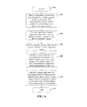
- FIG. 5 is a flow diagram of the method of calculating the impedance loss model parameters of FIG. 4 .
- the sensed voltage is converted to a peak voltage value based upon the predicted phase value (step 502).
- the sensed current is converted to a peak current value based upon the predicted phase value (step 504).
- the loss model parameter is back calculated based upon the peak voltage value, the peak current value, and the desired load impedance value
- FIG. 6 is a flow diagram of a method of calibrating impedance loss model parameters, i.e., a source impedance parameter and a leakage impedance parameter, according to other embodiments of the present disclosure.
- This calibration method uses multiple test loads having a range of rated resistance or impedance values because the reactance of the transmission lines or cables of the electrosurgical system varies based upon the impedance of the tissue. For example, source impedance losses are dominant for low resistance loads and leakage impedance losses are dominant for high resistance loads.
- the resistance of the power resistors may range between 0 ohms and 5000 ohms. In other embodiments, the resistance of the power resistors may range between 0 ohms and 1500 ohms.
- a voltage and a current is sensed or measured across each of a plurality of test loads, e.g., power resistors, which are separately coupled to an output of the electrosurgical system to obtain a plurality of sensed voltages and a plurality of sensed currents (step 602).
- Voltage and current measurements are taken after an operating mode, e.g., bipolar standard, and an output port of the electrosurgical system, if any, are selected.
- the control is set to closed-loop control and the output power is set to a desired level, e.g., 50W for bipolar standard.
- the rms voltage and rms current applied to each of the test loads are measured using the ADCs 215 disposed within the electrosurgical generators as shown in FIGS. 1 and 2 .
- the sensed voltages and currents are used to calculate sensor impedance values for each of the test loads (step 604).
- These sensor impedance values are then used to predict the phase between the sensed voltage and sensed current for each of the test loads (step 606).
- the predicted phase value may be calculated according to a polynomial function of the sensor impedance values.
- the polynomial function may be determined using known curve fitting techniques.
- the curve fitting techniques are used to approximate the change in phase based on absolute impedance measured over a varying external load ranging from a minimum load (e.g., 0 ohms) to a maximum load (e.g., 1500 or 5000 ohms) given a fixed internal source impedance and a fixed internal leakage impedance.
- a minimum load e.g., 0 ohms
- a maximum load e.g. 1500 or 5000 ohms
- the real impedance i.e., tissue resistance
- the imaginary impedance i.e., reactance
- the polynomial coefficients of the polynomial function determined by a curve fitting technique are unique for each particular generator.
- the imaginary impedance i.e., reactance
- the imaginary impedance may be fixed across various manufacturing instances of a particular type of generator by specifying the number of turns of the RF transmission wires internal to the generator.
- a common set of polynomial coefficients can be used for all generators of that particular type.
- the test loads are separately connected to the leads of an impedance meter, e.g., an LCR meter, via test cables, e.g., short banana cables, to measure the impedance of each of the test loads.
- an impedance meter e.g., an LCR meter
- test cables e.g., short banana cables
- the following power resistors having the following respective rated resistances may be measured to obtain the following respective measured impedance values: Power Resistor Rated Resistance (ohms) Measured Impedance (ohms) Zload_05 5 5.0 + 2.0i Zload_10 10 10.01 + 3.0i Zload_20 20 20.01 + 5.07 ⁇ i Zload_50 50 50.08 + 1.62 ⁇ i Zload_100 100 100.43 + 6.40 ⁇ i Zload_200 200 201.05 + 7.54 ⁇ i Zload_300 300 301.35 + 9.74 ⁇ i Zload_500 500 502.24 + 3.84 ⁇ i Zload_1000 1000 1001.0 - 6.62 ⁇
- the power resistors may further include a power resistor having a rated resistance of 0 ohms. If the impedance of the test cables, e.g., short banana cables, and the impedance of the test loads, e.g., power resistors, are measured together, then the impedances of the test cables is not included in the calibration calculations. If, on the other hand, the impedance of the test cables is measured separately from the impedance of the power resistors, then the impedance of the test cables are included in the calibration calculations. For example, the measured impedance of a first test cable (Cable1) may be 0.0533 + 2.12i ohms and the measured impedance of a second test cable (Cable 2) may be 0.0305 + 1.62i ohms.
- the measured rms voltage, the measured rms current, the calculated phase, and the actual measured impedances of the test loads and test cable are formed into an input array, e.g.: V sense ( rms ) I sense ( rms ) ⁇ VI Z load ( actual ) 5.87354 1.79432 -0.1749941 Cable1 + Cable2 10.236 1.4174247 -0.1725 Zload_05 + Cable1 + Cable2 20.290839 1.5947771 -0.1694 Zload_10 + Cable1 + Cable2 49.453838 2.0342297 -0.162798 Zload_20 + Cable1 + Cable2 89.06355 1.681512 -0.146599 Zload_50 + Cable1 + Cable2 90.157114 0.901156 -0.1203367 Zload_100 + Cable1 + Cable2 89.970472 0.4828364 -0.0733272 Zload_200 + Cable1 + Cable2 89.78422 0.
- a source impedance parameter is calculated based upon a first predicted phase value, a first sensed voltage, a first sensed current, and a first predetermined load impedance value corresponding to a first load.
- a leakage impedance parameter is calculated based upon a second predicted phase value, a second sensed voltage, a second sensed current, and a second predetermined load impedance value corresponding to a second load.
- the first and second predetermined load impedance values are obtained by measuring the impedances of the first and second loads, respectively, using an impedance meter.
- the first and second predetermined load impedance values are selected from a plurality of predetermined load impedance values that are obtained by measuring the impedances of a plurality of loads using an impedance meter.
- the impedance loss model parameters are calculated using a back-calculation technique.
- appropriate test load data is first selected to optimize measurement accuracy across a range of loads.
- low impedance data e.g., the data for the 5 ohm load
- high impedance data e.g., the data for the 1500 ohm load
- the impedance loss model parameters are calculated based upon measurement data (e.g., sensed voltage, sensed current, sensed phase, and predetermined impedance) for different test loads.
- measurement data e.g., sensed voltage, sensed current, sensed phase, and predetermined impedance
- the source impedance loss model parameter is calculated based upon the measurement data for a low impedance load
- the leakage impedance loss model parameter is calculated based upon the measurement data for a high impedance load.
- FIG. 7 is a flow diagram of a method of calculating the source impedance loss model parameter of FIG. 6 .
- the first sensed voltage e.g., a first voltage sensed by the voltage sensor 211 with a low impedance test load placed across the electrodes 303, 304
- the first sensed current e.g., a first current sensed by the current sensor 212 with a low impedance test load placed across the electrodes 303, 304
- the first sensed current e.g., a first current sensed by the current sensor 212 with a low impedance test load placed across the electrodes 303, 304 is converted to a first peak current value based upon the first predicted phase value.
- a first output voltage value is calculated based upon the first peak voltage value, the first peak current value, and a previous source impedance loss model parameter (also referred to herein as a previous source impedance parameter) (step 704).
- the previous source impedance parameter and the previous leakage impedance parameter are set to initial values before a first iteration of the loss model calibration procedure.
- a first output current value is calculated based upon the first output voltage value, the peak current value, and a previous leakage impedance loss model parameter (also referred to herein as a previous leakage impedance parameter) (step 706).
- the source impedance loss model parameter is back calculated based upon the first output current value, the first predetermined load impedance value (e.g., a premeasured impedance value of a first test load), the first peak voltage value, and the first peak current value (step 708).
- the first predetermined load impedance value e.g., a premeasured impedance value of a first test load
- the first peak voltage value e.g., a premeasured impedance value of a first test load
- the first peak current value e.g., a premeasured impedance value of a first test load
- a method of back calculating the source impedance loss model parameter is shown in FIG. 10 .
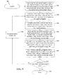
- FIG. 8 is a flow diagram of a method of calculating the leakage impedance loss model parameter of FIG. 6 .
- a second sensed voltage e.g., a second voltage sensed by the voltage sensor 211 with a high impedance test load placed across the electrodes 303, 304
- a second sensed current e.g., a second current sensed by the current sensor 212 with a high impedance test load placed across the electrodes 303, 304
- a second peak current e.g., a second current sensed by the current sensor 212 with a high impedance test load placed across the electrodes 303, 304 is converted to a second peak current value based upon a second predicted phase value.
- a second output voltage value is calculated based upon the second peak voltage value, the second peak current value, and the previous source impedance loss model parameter (step 804).
- the leakage impedance loss model parameter is back calculated based upon the second output voltage value, the second predetermined load impedance value (e.g., a premeasured impedance value of a second test load), and the second peak current value (step 708).
- the second predetermined load impedance value e.g., a premeasured impedance value of a second test load
- the second peak current value step 708
- a method of back calculating the leakage impedance loss model parameter is shown in FIG. 11 .
- the source impedance loss model parameter and the leakage impedance loss model parameter are calculated together in an iterative manner.
- An example method of iteratively calculating the impedance loss model parameters is shown in the flow diagram of FIG. 9 .
- first and second sensed voltages are converted to first and second peak voltage values and first and second sensed current values are converted to first and second peak current values based upon first and second predicted phase values.
- steps 904-908 which are identical to steps 704-708 of FIG. 7
- the source impedance loss model parameter is calculated.
- steps 910-912 which are identical to steps 804-806 of FIG. 8
- the leakage impedance loss model parameter is calculated.
- step 914 it is determined whether the number of iterations is greater than a predetermined value. If it is determined that the number of iterations is greater than the predetermined value, then the method of calculating the impedance loss model parameters ends in step 917. Otherwise, the number of iterations is incremented (e.g., by one) in step 916 and steps 904-912 are repeated.
- the predetermined value is set to a number of iterations that produces accurate impedance loss model parameters.
- the calibration computer system 340 includes a first DSP 341 and a second DSP 342.
- the first DSP 341 calculates the source and leakage impedance loss model parameters according to the various methods described above and the second DSP 342 performs the same calculations.
- the impedance loss model parameters calculated by the DSPs 341, 342 are averaged to obtain an average source impedance parameter and an average leakage impedance parameter.
- the processor 242 receives the average source impedance parameter and the average leakage impedance parameter and transmits them to the controller 220 via the communications interface 245.
- the calibration computer system 340 is implemented in the controller 220 or the portable electrosurgical device 301 of FIG. 3 .
- the calibrated impedance loss model parameters are used to compensate for the effect of impedance losses on the accuracy of the power and/or impedance measurements at the load.
- the compensation process involves sensing a voltage and a current of an electrosurgical signal generated by and applied to a tissue site by the electrosurgical device (step 1202), predicting a phase value based upon the sensed voltage and the sensed current (step 1204), and calculating at least one metric at the tissue site based upon the sensed voltage, the sensed current, the predicted phase value, and at least one impedance loss model parameter associated with the electrosurgical system (step 1206).
- the at least one metric at the tissue site includes voltage, current, power, and/or impedance.
- the at least one impedance loss model parameter includes a source impedance parameter and/or a leakage impedance parameter.
- calculating the at least one metric at the tissue site includes converting the sensed voltage to a complex voltage value based upon the predicted phase value (step 1302), converting the sensed current to a complex current value based upon the predicted phase value (step 1302); and calculating the at least one metric at the tissue site based upon the complex voltage value, the complex current value, and the at least one loss model parameter (step 1304).
- predicting the phase value includes calculating a sensed impedance value based upon the sensed voltage and the sensed current (1402) and predicting the phase value based upon the sensed impedance value (1404).
- predicting the phase value is based upon a polynomial function of the sensed impedance value.
- the polynomial function may be a third-order polynomial function.
- calculating the at least one metric at the tissue site includes performing network solution calculations to determine the impedance at the tissue site. These calculations first involved multiplying the sensed current ( I sense ) by the source impedance parameter ( Z source ) to obtain a source impedance voltage value V Z source (step 1502). In step 1504, the source impedance voltage value V Z source is subtracted from the sensed voltage ( V sense ) to obtain a load voltage value ( V load ). In step 1506, the load voltage value ( V load ) is divided by the leakage impedance parameter ( Z leakage ) to obtain a leakage current value ( I leakage ).
- step 1508 the leakage current value ( I leakage ) is subtracted from the sensed current ( I sense ) to obtain a load current value ( I load ).
- step 1510 the load voltage value ( V load ) is divided by the load current value ( I load ) to obtain the load impedance value ( Z load ).
- the load voltage value (V load ) and the load current value ( I load ) can also be used to calculate the power at the tissue site.
Landscapes
- Health & Medical Sciences (AREA)
- Surgery (AREA)
- Engineering & Computer Science (AREA)
- Life Sciences & Earth Sciences (AREA)
- Biomedical Technology (AREA)
- Molecular Biology (AREA)
- Nuclear Medicine, Radiotherapy & Molecular Imaging (AREA)
- Plasma & Fusion (AREA)
- Physics & Mathematics (AREA)
- Heart & Thoracic Surgery (AREA)
- Medical Informatics (AREA)
- Otolaryngology (AREA)
- Animal Behavior & Ethology (AREA)
- General Health & Medical Sciences (AREA)
- Public Health (AREA)
- Veterinary Medicine (AREA)
- Surgical Instruments (AREA)
- Measurement And Recording Of Electrical Phenomena And Electrical Characteristics Of The Living Body (AREA)
Applications Claiming Priority (1)
| Application Number | Priority Date | Filing Date | Title |
|---|---|---|---|
| US13/360,289 US9037447B2 (en) | 2012-01-27 | 2012-01-27 | Systems and methods for phase predictive impedance loss model calibration and compensation |
Publications (2)
| Publication Number | Publication Date |
|---|---|
| EP2620114A1 true EP2620114A1 (fr) | 2013-07-31 |
| EP2620114B1 EP2620114B1 (fr) | 2016-03-30 |
Family
ID=47681663
Family Applications (1)
| Application Number | Title | Priority Date | Filing Date |
|---|---|---|---|
| EP13151439.0A Not-in-force EP2620114B1 (fr) | 2012-01-27 | 2013-01-16 | Systèmes pour étalonnage et compensation de modèle prédictif de perte d'impédance de phase |
Country Status (6)
| Country | Link |
|---|---|
| US (1) | US9037447B2 (fr) |
| EP (1) | EP2620114B1 (fr) |
| JP (2) | JP2013154167A (fr) |
| CN (1) | CN103222892B (fr) |
| AU (1) | AU2012268927B2 (fr) |
| CA (1) | CA2799125A1 (fr) |
Cited By (2)
| Publication number | Priority date | Publication date | Assignee | Title |
|---|---|---|---|---|
| GB2514100A (en) * | 2013-05-08 | 2014-11-19 | Creo Medical Ltd | Method and Apparatus for Controlling Power Delivered by Electrosurgical Probe |
| WO2023023053A1 (fr) * | 2021-08-17 | 2023-02-23 | Fluke Corporation | Systèmes et procédés d'étalonnage utilisant une simulation d'impédance |
Families Citing this family (29)
| Publication number | Priority date | Publication date | Assignee | Title |
|---|---|---|---|---|
| US8568411B2 (en) | 2008-03-31 | 2013-10-29 | Applied Medical Resources Corporation | Electrosurgical system |
| EP3332723B1 (fr) | 2010-10-01 | 2022-02-16 | Applied Medical Resources Corporation | Instruments électrochirurgicaux et connexions à ceux-ci |
| US9480523B2 (en) * | 2012-01-27 | 2016-11-01 | Covidien Lp | Systems and methods for phase predictive impedance loss model calibration and compensation |
| US9192425B2 (en) | 2012-06-26 | 2015-11-24 | Covidien Lp | System and method for testing electrosurgical generators |
| US9529025B2 (en) | 2012-06-29 | 2016-12-27 | Covidien Lp | Systems and methods for measuring the frequency of signals generated by high frequency medical devices |
| US9456862B2 (en) | 2013-02-19 | 2016-10-04 | Covidien Lp | Electrosurgical generator and system |
| US9895186B2 (en) | 2013-03-11 | 2018-02-20 | Covidien | Systems and methods for detecting abnormalities within a circuit of an electrosurgical generator |
| US9519021B2 (en) | 2013-03-11 | 2016-12-13 | Covidien Lp | Systems and methods for detecting abnormalities within a circuit of an electrosurgical generator |
| US9283028B2 (en) | 2013-03-15 | 2016-03-15 | Covidien Lp | Crest-factor control of phase-shifted inverter |
| US9498276B2 (en) * | 2013-03-15 | 2016-11-22 | Covidien Lp | Systems and methods for narrowband real impedance control in electrosurgery |
| US10729484B2 (en) | 2013-07-16 | 2020-08-04 | Covidien Lp | Electrosurgical generator with continuously and arbitrarily variable crest factor |
| US10610285B2 (en) | 2013-07-19 | 2020-04-07 | Covidien Lp | Electrosurgical generators |
| US9872719B2 (en) | 2013-07-24 | 2018-01-23 | Covidien Lp | Systems and methods for generating electrosurgical energy using a multistage power converter |
| US9636165B2 (en) | 2013-07-29 | 2017-05-02 | Covidien Lp | Systems and methods for measuring tissue impedance through an electrosurgical cable |
| US9770283B2 (en) | 2013-09-24 | 2017-09-26 | Covidien Lp | Systems and methods for improving efficiency of electrosurgical generators |
| US9839469B2 (en) | 2013-09-24 | 2017-12-12 | Covidien Lp | Systems and methods for improving efficiency of electrosurgical generators |
| US9901385B2 (en) | 2014-01-13 | 2018-02-27 | Covidien Lp | Systems and methods for multifrequency cable compensation |
| AU2015258819B2 (en) | 2014-05-16 | 2019-12-12 | Applied Medical Resources Corporation | Electrosurgical system |
| JP6608449B2 (ja) * | 2014-09-05 | 2019-11-20 | エシコン エルエルシー | 組織圧縮を定量化するための一体化センサを有する付加物 |
| JP6001225B1 (ja) * | 2014-10-31 | 2016-10-05 | オリンパス株式会社 | エネルギー処置装置 |
| KR102545505B1 (ko) | 2014-12-23 | 2023-06-20 | 어플라이드 메디컬 리소시스 코포레이션 | 바이폴라 전기수술용 밀봉기 및 디바이더 |
| CN106667547A (zh) * | 2016-06-23 | 2017-05-17 | 山东威瑞外科医用制品有限公司 | 超声刀刀杆谐振控制装置及控制方法 |
| CN107569229B (zh) * | 2017-09-04 | 2021-02-02 | 歌尔科技有限公司 | 一种生物阻抗测量方法、装置及电子设备 |
| WO2020051369A1 (fr) | 2018-09-05 | 2020-03-12 | Applied Medical Resources Corporation | Système de commande de générateur électrochirurgical |
| KR20210057753A (ko) * | 2018-09-05 | 2021-05-21 | 어플라이드 메디컬 리소시스 코포레이션 | 전기수술용 발전기 검증 시스템 |
| WO2020101954A1 (fr) | 2018-11-16 | 2020-05-22 | Applied Medical Resources Corporation | Système électrochirurgical |
| SG11202111518WA (en) | 2019-05-09 | 2021-11-29 | Gyrus Acmi Inc D/B/A Olympus Surgical Technologies America | Electrosurgical systems and methods |
| TWI693919B (zh) * | 2019-07-08 | 2020-05-21 | 國立虎尾科技大學 | 手術器械的放電測試方法 |
| CN114831725B (zh) * | 2022-05-05 | 2024-01-26 | 以诺康医疗科技(苏州)有限公司 | 一种电外科发生器、电外科系统及其控制方法 |
Citations (11)
| Publication number | Priority date | Publication date | Assignee | Title |
|---|---|---|---|---|
| US5743900A (en) * | 1995-06-06 | 1998-04-28 | Sun Star Technology, Inc. | Hot tip catheter and method for using the same |
| US5843021A (en) * | 1994-05-09 | 1998-12-01 | Somnus Medical Technologies, Inc. | Cell necrosis apparatus |
| US6019757A (en) * | 1995-07-07 | 2000-02-01 | Target Therapeutics, Inc. | Endoluminal electro-occlusion detection apparatus and method |
| US20060224152A1 (en) * | 2005-03-31 | 2006-10-05 | Sherwood Services Ag | Method and system for compensating for external impedance of an energy carrying component when controlling an electrosurgical generator |
| US20070173804A1 (en) * | 2006-01-24 | 2007-07-26 | Wham Robert H | System and method for tissue sealing |
| WO2008063195A1 (fr) * | 2006-10-12 | 2008-05-29 | St. Jude Medical, Atrial Fibrillation Division, Inc. | Evaluation de couplage d'électrode pour ablation tissulaire |
| US20090018536A1 (en) * | 2007-07-11 | 2009-01-15 | Robert Behnke | Measurement and control systems and methods for electrosurgical procedures |
| US20100121318A1 (en) * | 2006-10-10 | 2010-05-13 | Medical Device Innovations Limited | Apparatus for treating tissue with microwave radiation and antenna calibration system and method |
| US20110112526A1 (en) * | 2008-06-30 | 2011-05-12 | Martin Fritz | Electrosurgical generator for the treatment of a biological tissue, method for regulating an output voltage of an electrosurgical generator, and corresponding use of the electrosurgical generator |
| US20110144635A1 (en) * | 2009-12-16 | 2011-06-16 | Tyco Healthcare Group Lp | System and Method for Tissue Sealing |
| WO2011126580A2 (fr) * | 2010-04-09 | 2011-10-13 | Minnow Medical, Inc. | Appareil de commande et de production d'énergie destiné au traitement de tissus |
Family Cites Families (97)
| Publication number | Priority date | Publication date | Assignee | Title |
|---|---|---|---|---|
| DE179607C (fr) | 1906-11-12 | |||
| DE390937C (de) | 1922-10-13 | 1924-03-03 | Adolf Erb | Vorrichtung zur Innenbeheizung von Wannenoefen zum Haerten, Anlassen, Gluehen, Vergueten und Schmelzen |
| DE1099658B (de) | 1959-04-29 | 1961-02-16 | Siemens Reiniger Werke Ag | Selbsttaetige Einschaltvorrichtung fuer Hochfrequenzchirurgiegeraete |
| FR1275415A (fr) | 1960-09-26 | 1961-11-10 | Dispositif détecteur de perturbations pour installations électriques, notamment d'électrochirurgie | |
| DE1139927B (de) | 1961-01-03 | 1962-11-22 | Friedrich Laber | Hochfrequenz-Chirurgiegeraet |
| DE1149832C2 (de) | 1961-02-25 | 1977-10-13 | Siemens AG, 1000 Berlin und 8000 München | Hochfrequenz-chirurgieapparat |
| FR1347865A (fr) | 1962-11-22 | 1964-01-04 | Perfectionnements aux appareils de diathermo-coagulation | |
| DE1439302B2 (de) | 1963-10-26 | 1971-05-19 | Siemens AG, 1000 Berlin u 8000 München | Hochfrequenz Chirurgiegerat |
| GB1480736A (en) | 1973-08-23 | 1977-07-20 | Matburn Ltd | Electrodiathermy apparatus |
| FR2251864A1 (en) | 1973-11-21 | 1975-06-13 | Termiflex Corp | Portable input and output unit for connection to a data processor - is basically a calculator with transmitter and receiver |
| DE2407559C3 (de) | 1974-02-16 | 1982-01-21 | Dornier System Gmbh, 7990 Friedrichshafen | Wärmesonde |
| US4237887A (en) | 1975-01-23 | 1980-12-09 | Valleylab, Inc. | Electrosurgical device |
| DE2504280C3 (de) | 1975-02-01 | 1980-08-28 | Hans Heinrich Prof. Dr. 8035 Gauting Meinke | Vorrichtung zum Schneiden und/oder Koagulieren menschlichen Gewebes mit Hochfrequenzstrom |
| CA1064581A (fr) | 1975-06-02 | 1979-10-16 | Stephen W. Andrews | Circuit de controle de pulsations et methode pour appareil d'electrochirurgie |
| DE2540968C2 (de) | 1975-09-13 | 1982-12-30 | Erbe Elektromedizin GmbH, 7400 Tübingen | Einrichtung zum Einschalten des Koagulationsstroms einer bipolaren Koagulationspinzette |
| US4094320A (en) | 1976-09-09 | 1978-06-13 | Valleylab, Inc. | Electrosurgical safety circuit and method of using same |
| FR2390968A1 (fr) | 1977-05-16 | 1978-12-15 | Skovajsa Joseph | Dispositif de traitement local d'un patient, notamment pour acupuncture ou auriculotherapie |
| SU727201A2 (ru) | 1977-11-02 | 1980-04-15 | Киевский Научно-Исследовательский Институт Нейрохирургии | Электрохирургический аппарат |
| DE2803275C3 (de) | 1978-01-26 | 1980-09-25 | Aesculap-Werke Ag Vormals Jetter & Scheerer, 7200 Tuttlingen | Fernschalteinrichtung zum Schalten eines monopolaren HF-Chirurgiegerätes |
| DE2823291A1 (de) | 1978-05-27 | 1979-11-29 | Rainer Ing Grad Koch | Schaltung zur automatischen einschaltung des hochfrequenzstromes von hochfrequenz-koagulationsgeraeten |
| DE2946728A1 (de) | 1979-11-20 | 1981-05-27 | Erbe Elektromedizin GmbH & Co KG, 7400 Tübingen | Hochfrequenz-chirurgiegeraet |
| JPS5778844A (en) | 1980-11-04 | 1982-05-17 | Kogyo Gijutsuin | Lasre knife |
| DE3045996A1 (de) | 1980-12-05 | 1982-07-08 | Medic Eschmann Handelsgesellschaft für medizinische Instrumente mbH, 2000 Hamburg | Elektro-chirurgiegeraet |
| FR2502935B1 (fr) | 1981-03-31 | 1985-10-04 | Dolley Roger | Procede et dispositif de controle de la coagulation de tissus a l'aide d'un courant a haute frequence |
| DE3120102A1 (de) | 1981-05-20 | 1982-12-09 | F.L. Fischer GmbH & Co, 7800 Freiburg | Anordnung zur hochfrequenzkoagulation von eiweiss fuer chirurgische zwecke |
| FR2517953A1 (fr) | 1981-12-10 | 1983-06-17 | Alvar Electronic | Appareil diaphanometre et son procede d'utilisation |
| US4727874A (en) * | 1984-09-10 | 1988-03-01 | C. R. Bard, Inc. | Electrosurgical generator with high-frequency pulse width modulated feedback power control |
| FR2573301B3 (fr) | 1984-11-16 | 1987-04-30 | Lamidey Gilles | Pince chirurgicale et son appareillage de commande et de controle |
| DE3510586A1 (de) | 1985-03-23 | 1986-10-02 | Erbe Elektromedizin GmbH, 7400 Tübingen | Kontrolleinrichtung fuer ein hochfrequenz-chirurgiegeraet |
| DE3604823C2 (de) | 1986-02-15 | 1995-06-01 | Lindenmeier Heinz | Hochfrequenzgenerator mit automatischer Leistungsregelung für die Hochfrequenzchirurgie |
| EP0246350A1 (fr) | 1986-05-23 | 1987-11-25 | Erbe Elektromedizin GmbH. | Electrode pour coaguler |
| JPS635876A (ja) | 1986-06-27 | 1988-01-11 | Hitachi Seiko Ltd | ア−ク溶接機 |
| DE3638748A1 (de) | 1986-11-13 | 1988-06-01 | Hirschmann Radiotechnik | Kapazitives trennglied |
| US5073167A (en) | 1987-06-26 | 1991-12-17 | M/A-Com, Inc. | In-line microwave warming apparatus |
| US4931047A (en) | 1987-09-30 | 1990-06-05 | Cavitron, Inc. | Method and apparatus for providing enhanced tissue fragmentation and/or hemostasis |
| EP0325456B1 (fr) | 1988-01-20 | 1995-12-27 | G2 Design Limited | Appareil de diathermie |
| EP0336742A3 (fr) | 1988-04-08 | 1990-05-16 | Bristol-Myers Company | Méthode et appareillage pour la calibration d'appareils électro-chirurgicaux |
| DE3904558C2 (de) | 1989-02-15 | 1997-09-18 | Lindenmeier Heinz | Automatisch leistungsgeregelter Hochfrequenzgenerator für die Hochfrequenz-Chirurgie |
| EP0390937B1 (fr) | 1989-04-01 | 1994-11-02 | Erbe Elektromedizin GmbH | Dispositif pour surveiller l'adhésion des électrodes neutres utilisées en chirurgie à haute fréquence |
| JPH0634792B2 (ja) * | 1989-10-18 | 1994-05-11 | アロカ株式会社 | 電気手術器 |
| DE3942998C2 (de) | 1989-12-27 | 1998-11-26 | Delma Elektro Med App | Elektrochirurgisches Hochfrequenzgerät |
| DE4205213A1 (de) | 1992-02-20 | 1993-08-26 | Delma Elektro Med App | Hochfrequenzchirurgiegeraet |
| DE4206433A1 (de) | 1992-02-29 | 1993-09-02 | Bosch Gmbh Robert | Kapazitives trennstueck |
| US5502392A (en) * | 1992-04-30 | 1996-03-26 | International Business Machines Corporation | Methods for the measurement of the frequency dependent complex propagation matrix, impedance matrix and admittance matrix of coupled transmission lines |
| US5348554A (en) | 1992-12-01 | 1994-09-20 | Cardiac Pathways Corporation | Catheter for RF ablation with cooled electrode |
| US5370645A (en) * | 1993-04-19 | 1994-12-06 | Valleylab Inc. | Electrosurgical processor and method of use |
| US5372596A (en) * | 1993-07-27 | 1994-12-13 | Valleylab Inc. | Apparatus for leakage control and method for its use |
| DE4339049C2 (de) | 1993-11-16 | 2001-06-28 | Erbe Elektromedizin | Einrichtung zur Konfiguration chirurgischer Systeme |
| DE19506363A1 (de) | 1995-02-24 | 1996-08-29 | Frost Lore Geb Haupt | Verfahren zur nicht-invasiven Thermometrie in Organen unter medizinischen Hyperthermie- und Koagulationsbedingungen |
| US6322558B1 (en) | 1995-06-09 | 2001-11-27 | Engineering & Research Associates, Inc. | Apparatus and method for predicting ablation depth |
| US5837001A (en) * | 1995-12-08 | 1998-11-17 | C. R. Bard | Radio frequency energy delivery system for multipolar electrode catheters |
| DE19643127A1 (de) | 1996-10-18 | 1998-04-23 | Berchtold Gmbh & Co Geb | Hochfrequenzchirurgiegerät und Verfahren zu dessen Betrieb |
| CA2285469A1 (fr) | 1997-04-04 | 1998-10-15 | Samuel G. Netherly | Procede et appareil permettant d'apprecier le contact d'electrodes biomedicales avec la peau d'un patient |
| DE19717411A1 (de) | 1997-04-25 | 1998-11-05 | Aesculap Ag & Co Kg | Verfahren und Vorrichtung zur Überwachung der thermischen Belastung des Gewebes eines Patienten |
| US5838558A (en) | 1997-05-19 | 1998-11-17 | Trw Inc. | Phase staggered full-bridge converter with soft-PWM switching |
| DE59712260D1 (de) | 1997-06-06 | 2005-05-12 | Endress & Hauser Gmbh & Co Kg | Mit Mikrowellen arbeitendes Füllstandsmessgerät |
| DE19757720A1 (de) * | 1997-12-23 | 1999-06-24 | Sulzer Osypka Gmbh | Verfahren zum Betrieb einer Hochfrequenz-Ablationsvorrichtung und Vorrichtung für die Hochfrequenz-Gewebe-Ablation |
| DE19848540A1 (de) | 1998-10-21 | 2000-05-25 | Reinhard Kalfhaus | Schaltungsanordnung und Verfahren zum Betreiben eines Wechselrichters |
| US6486569B2 (en) * | 1998-12-04 | 2002-11-26 | Hydro-Quebec | Power flow management in an electric power grid |
| US6203541B1 (en) | 1999-04-23 | 2001-03-20 | Sherwood Services Ag | Automatic activation of electrosurgical generator bipolar output |
| GB9913652D0 (en) * | 1999-06-11 | 1999-08-11 | Gyrus Medical Ltd | An electrosurgical generator |
| EP1307154B1 (fr) | 2000-08-08 | 2005-02-23 | Erbe Elektromedizin GmbH | Generateur a haute frequence pour la chirurgie haute frequence a limitation de puissance ajustable |
| JP4499893B2 (ja) | 2000-08-23 | 2010-07-07 | オリンパス株式会社 | 電気手術装置 |
| DE10061278B4 (de) | 2000-12-08 | 2004-09-16 | GFD-Gesellschaft für Diamantprodukte mbH | Instrument für chirurgische Zwecke |
| US6870359B1 (en) * | 2001-12-14 | 2005-03-22 | Le Croy Corporation | Self-calibrating electrical test probe |
| US7317948B1 (en) * | 2002-02-12 | 2008-01-08 | Boston Scientific Scimed, Inc. | Neural stimulation system providing auto adjustment of stimulus output as a function of sensed impedance |
| US6701335B2 (en) * | 2002-02-27 | 2004-03-02 | Lecroy Corporation | Digital frequency response compensator and arbitrary response generator system |
| DE10218895B4 (de) | 2002-04-26 | 2006-12-21 | Storz Endoskop Produktions Gmbh | Hochfrequenz-Chirurgiegenerator |
| AU2003265987A1 (en) * | 2002-09-09 | 2004-03-29 | American Superconductor Corporation | Low impedance transmission line with a power flow controller |
| US7300435B2 (en) | 2003-11-21 | 2007-11-27 | Sherwood Services Ag | Automatic control system for an electrosurgical generator |
| DE102004054575A1 (de) | 2004-11-11 | 2006-05-24 | Erbe Elektromedizin Gmbh | Regelung für ein HF-Chirurgiegerät |
| DE102005025946A1 (de) * | 2005-01-26 | 2006-08-03 | Erbe Elektromedizin Gmbh | HF-Chirurgieeinrichtung |
| US8734438B2 (en) | 2005-10-21 | 2014-05-27 | Covidien Ag | Circuit and method for reducing stored energy in an electrosurgical generator |
| US9186200B2 (en) | 2006-01-24 | 2015-11-17 | Covidien Ag | System and method for tissue sealing |
| US7660685B2 (en) * | 2006-08-02 | 2010-02-09 | Lecroy Corporation | Virtual probing |
| US7799020B2 (en) * | 2006-10-02 | 2010-09-21 | Conmed Corporation | Near-instantaneous responsive closed loop control electrosurgical generator and method |
| CN101534733B (zh) | 2006-10-31 | 2011-12-07 | 奥林巴斯医疗株式会社 | 高频烧灼电源装置 |
| USD574323S1 (en) | 2007-02-12 | 2008-08-05 | Tyco Healthcare Group Lp | Generator |
| US7755371B2 (en) * | 2007-02-27 | 2010-07-13 | Osisoft, Inc. | Impedance measurement of a power line |
| US8120259B2 (en) * | 2007-04-19 | 2012-02-21 | Plasmart Co., Ltd. | Impedance matching methods and systems performing the same |
| KR100870121B1 (ko) * | 2007-04-19 | 2008-11-25 | 주식회사 플라즈마트 | 임피던스 매칭 방법 및 이 방법을 위한 매칭 시스템 |
| US8216220B2 (en) | 2007-09-07 | 2012-07-10 | Tyco Healthcare Group Lp | System and method for transmission of combined data stream |
| WO2009078216A1 (fr) * | 2007-12-18 | 2009-06-25 | Kabushiki Kaisha Yaskawa Denki | Dispositif de commande de moteur à induction et son procédé de mesure/calcul de constante de moteur |
| US9987072B2 (en) | 2008-03-17 | 2018-06-05 | Covidien Lp | System and method for detecting a fault in a capacitive return electrode for use in electrosurgery |
| US8500727B2 (en) * | 2008-05-13 | 2013-08-06 | Megadyne Medical Products, Inc. | Methods, systems, and devices for performing electrosurgical procedures |
| DE102008058737B4 (de) | 2008-09-08 | 2019-12-12 | Erbe Elektromedizin Gmbh | HF-Chirurgiegenerator |
| US8262652B2 (en) * | 2009-01-12 | 2012-09-11 | Tyco Healthcare Group Lp | Imaginary impedance process monitoring and intelligent shut-off |
| US8162932B2 (en) * | 2009-01-12 | 2012-04-24 | Tyco Healthcare Group Lp | Energy delivery algorithm impedance trend adaptation |
| US8152802B2 (en) * | 2009-01-12 | 2012-04-10 | Tyco Healthcare Group Lp | Energy delivery algorithm filter pre-loading |
| US8377054B2 (en) | 2009-09-24 | 2013-02-19 | Covidien Lp | Automatic control circuit for use in an electrosurgical generator |
| US8568401B2 (en) | 2009-10-27 | 2013-10-29 | Covidien Lp | System for monitoring ablation size |
| CN101862219B (zh) | 2010-06-01 | 2011-12-21 | 谭伟 | 射频消融探头 |
| US20120239020A1 (en) | 2011-03-15 | 2012-09-20 | Tyco Healthcare Group Lp | Geo-Location Addition to Electrosurgical Generator |
| US9375247B2 (en) | 2011-03-16 | 2016-06-28 | Covidien Lp | System and method for electrosurgical generator power measurement |
| US20120239025A1 (en) | 2011-03-17 | 2012-09-20 | Tyco Healthcare Group Lp | Isolated Current Sensor |
| US9539050B2 (en) | 2011-04-12 | 2017-01-10 | Covidien Lp | System and method for process monitoring and intelligent shut-off |
| US8968293B2 (en) | 2011-04-12 | 2015-03-03 | Covidien Lp | Systems and methods for calibrating power measurements in an electrosurgical generator |
-
2012
- 2012-01-27 US US13/360,289 patent/US9037447B2/en not_active Expired - Fee Related
- 2012-12-18 CA CA2799125A patent/CA2799125A1/fr not_active Abandoned
- 2012-12-20 AU AU2012268927A patent/AU2012268927B2/en not_active Ceased
-
2013
- 2013-01-16 EP EP13151439.0A patent/EP2620114B1/fr not_active Not-in-force
- 2013-01-22 JP JP2013008869A patent/JP2013154167A/ja not_active Ceased
- 2013-01-25 CN CN201310028706.4A patent/CN103222892B/zh not_active Expired - Fee Related
-
2014
- 2014-12-11 JP JP2014250567A patent/JP2015061668A/ja active Pending
Patent Citations (11)
| Publication number | Priority date | Publication date | Assignee | Title |
|---|---|---|---|---|
| US5843021A (en) * | 1994-05-09 | 1998-12-01 | Somnus Medical Technologies, Inc. | Cell necrosis apparatus |
| US5743900A (en) * | 1995-06-06 | 1998-04-28 | Sun Star Technology, Inc. | Hot tip catheter and method for using the same |
| US6019757A (en) * | 1995-07-07 | 2000-02-01 | Target Therapeutics, Inc. | Endoluminal electro-occlusion detection apparatus and method |
| US20060224152A1 (en) * | 2005-03-31 | 2006-10-05 | Sherwood Services Ag | Method and system for compensating for external impedance of an energy carrying component when controlling an electrosurgical generator |
| US20070173804A1 (en) * | 2006-01-24 | 2007-07-26 | Wham Robert H | System and method for tissue sealing |
| US20100121318A1 (en) * | 2006-10-10 | 2010-05-13 | Medical Device Innovations Limited | Apparatus for treating tissue with microwave radiation and antenna calibration system and method |
| WO2008063195A1 (fr) * | 2006-10-12 | 2008-05-29 | St. Jude Medical, Atrial Fibrillation Division, Inc. | Evaluation de couplage d'électrode pour ablation tissulaire |
| US20090018536A1 (en) * | 2007-07-11 | 2009-01-15 | Robert Behnke | Measurement and control systems and methods for electrosurgical procedures |
| US20110112526A1 (en) * | 2008-06-30 | 2011-05-12 | Martin Fritz | Electrosurgical generator for the treatment of a biological tissue, method for regulating an output voltage of an electrosurgical generator, and corresponding use of the electrosurgical generator |
| US20110144635A1 (en) * | 2009-12-16 | 2011-06-16 | Tyco Healthcare Group Lp | System and Method for Tissue Sealing |
| WO2011126580A2 (fr) * | 2010-04-09 | 2011-10-13 | Minnow Medical, Inc. | Appareil de commande et de production d'énergie destiné au traitement de tissus |
Cited By (5)
| Publication number | Priority date | Publication date | Assignee | Title |
|---|---|---|---|---|
| GB2514100A (en) * | 2013-05-08 | 2014-11-19 | Creo Medical Ltd | Method and Apparatus for Controlling Power Delivered by Electrosurgical Probe |
| US10299850B2 (en) | 2013-05-08 | 2019-05-28 | Creo Medical Limited | Method and apparatus for controlling power delivered by electrosurgical probe |
| GB2514100B (en) * | 2013-05-08 | 2020-04-01 | Creo Medical Ltd | Apparatus for Controlling Power Delivered by Electrosurgical Probe |
| WO2023023053A1 (fr) * | 2021-08-17 | 2023-02-23 | Fluke Corporation | Systèmes et procédés d'étalonnage utilisant une simulation d'impédance |
| CN117043621A (zh) * | 2021-08-17 | 2023-11-10 | 福禄克公司 | 使用阻抗模拟进行校准的系统和方法 |
Also Published As
| Publication number | Publication date |
|---|---|
| JP2015061668A (ja) | 2015-04-02 |
| EP2620114B1 (fr) | 2016-03-30 |
| US20130197874A1 (en) | 2013-08-01 |
| US9037447B2 (en) | 2015-05-19 |
| AU2012268927A1 (en) | 2013-08-15 |
| CN103222892B (zh) | 2016-02-24 |
| JP2013154167A (ja) | 2013-08-15 |
| CA2799125A1 (fr) | 2013-07-27 |
| CN103222892A (zh) | 2013-07-31 |
| AU2012268927B2 (en) | 2013-10-03 |
Similar Documents
| Publication | Publication Date | Title |
|---|---|---|
| EP2620113B1 (fr) | Systèmes et procédés pour étalonnage et compensation de modèle prédictif de perte d'impédance de phase | |
| US9037447B2 (en) | Systems and methods for phase predictive impedance loss model calibration and compensation | |
| US11076906B2 (en) | Logarithmic amplifier, electrosurgical generator including same, and method of controlling electrosurgical generator using same | |
| JP6410505B2 (ja) | 電気外科用ケーブルを通して組織インピーダンスを測定するシステムおよび方法 | |
| US10058374B2 (en) | Systems and methods for estimating tissue parameters using surgical devices | |
| US20150088116A1 (en) | Systems and methods for estimating tissue parameters using surgical devices | |
| EP2853222A1 (fr) | Systèmes et procédés pour estimer des paramètres tissulaires au moyen de dispositifs chirurgicaux | |
| WO2008102154A2 (fr) | Systèmes électrochirurgicaux | |
| US10568680B2 (en) | Electrosurgical system for multi-frequency interrogation of parasitic parameters of an electrosurgical instrument | |
| US10539595B2 (en) | Systems and methods for improving the range of sensor systems |
Legal Events
| Date | Code | Title | Description |
|---|---|---|---|
| PUAI | Public reference made under article 153(3) epc to a published international application that has entered the european phase |
Free format text: ORIGINAL CODE: 0009012 |
|
| 17P | Request for examination filed |
Effective date: 20130116 |
|
| AK | Designated contracting states |
Kind code of ref document: A1 Designated state(s): AL AT BE BG CH CY CZ DE DK EE ES FI FR GB GR HR HU IE IS IT LI LT LU LV MC MK MT NL NO PL PT RO RS SE SI SK SM TR |
|
| AX | Request for extension of the european patent |
Extension state: BA ME |
|
| GRAP | Despatch of communication of intention to grant a patent |
Free format text: ORIGINAL CODE: EPIDOSNIGR1 |
|
| RIC1 | Information provided on ipc code assigned before grant |
Ipc: A61B 17/00 20060101ALI20150724BHEP Ipc: A61B 18/14 20060101ALI20150724BHEP Ipc: A61B 18/00 20060101ALI20150724BHEP Ipc: A61B 18/12 20060101AFI20150724BHEP |
|
| INTG | Intention to grant announced |
Effective date: 20150820 |
|
| GRAS | Grant fee paid |
Free format text: ORIGINAL CODE: EPIDOSNIGR3 |
|
| GRAA | (expected) grant |
Free format text: ORIGINAL CODE: 0009210 |
|
| AK | Designated contracting states |
Kind code of ref document: B1 Designated state(s): AL AT BE BG CH CY CZ DE DK EE ES FI FR GB GR HR HU IE IS IT LI LT LU LV MC MK MT NL NO PL PT RO RS SE SI SK SM TR |
|
| REG | Reference to a national code |
Ref country code: GB Ref legal event code: FG4D |
|
| REG | Reference to a national code |
Ref country code: CH Ref legal event code: EP |
|
| REG | Reference to a national code |
Ref country code: AT Ref legal event code: REF Ref document number: 784456 Country of ref document: AT Kind code of ref document: T Effective date: 20160415 |
|
| REG | Reference to a national code |
Ref country code: IE Ref legal event code: FG4D |
|
| REG | Reference to a national code |
Ref country code: DE Ref legal event code: R096 Ref document number: 602013005821 Country of ref document: DE |
|
| REG | Reference to a national code |
Ref country code: LT Ref legal event code: MG4D |
|
| PG25 | Lapsed in a contracting state [announced via postgrant information from national office to epo] |
Ref country code: FI Free format text: LAPSE BECAUSE OF FAILURE TO SUBMIT A TRANSLATION OF THE DESCRIPTION OR TO PAY THE FEE WITHIN THE PRESCRIBED TIME-LIMIT Effective date: 20160330 Ref country code: NO Free format text: LAPSE BECAUSE OF FAILURE TO SUBMIT A TRANSLATION OF THE DESCRIPTION OR TO PAY THE FEE WITHIN THE PRESCRIBED TIME-LIMIT Effective date: 20160630 Ref country code: GR Free format text: LAPSE BECAUSE OF FAILURE TO SUBMIT A TRANSLATION OF THE DESCRIPTION OR TO PAY THE FEE WITHIN THE PRESCRIBED TIME-LIMIT Effective date: 20160701 Ref country code: HR Free format text: LAPSE BECAUSE OF FAILURE TO SUBMIT A TRANSLATION OF THE DESCRIPTION OR TO PAY THE FEE WITHIN THE PRESCRIBED TIME-LIMIT Effective date: 20160330 |
|
| REG | Reference to a national code |
Ref country code: NL Ref legal event code: MP Effective date: 20160330 |
|
| REG | Reference to a national code |
Ref country code: AT Ref legal event code: MK05 Ref document number: 784456 Country of ref document: AT Kind code of ref document: T Effective date: 20160330 |
|
| PG25 | Lapsed in a contracting state [announced via postgrant information from national office to epo] |
Ref country code: LT Free format text: LAPSE BECAUSE OF FAILURE TO SUBMIT A TRANSLATION OF THE DESCRIPTION OR TO PAY THE FEE WITHIN THE PRESCRIBED TIME-LIMIT Effective date: 20160330 Ref country code: RS Free format text: LAPSE BECAUSE OF FAILURE TO SUBMIT A TRANSLATION OF THE DESCRIPTION OR TO PAY THE FEE WITHIN THE PRESCRIBED TIME-LIMIT Effective date: 20160330 Ref country code: SE Free format text: LAPSE BECAUSE OF FAILURE TO SUBMIT A TRANSLATION OF THE DESCRIPTION OR TO PAY THE FEE WITHIN THE PRESCRIBED TIME-LIMIT Effective date: 20160330 Ref country code: LV Free format text: LAPSE BECAUSE OF FAILURE TO SUBMIT A TRANSLATION OF THE DESCRIPTION OR TO PAY THE FEE WITHIN THE PRESCRIBED TIME-LIMIT Effective date: 20160330 |
|
| PG25 | Lapsed in a contracting state [announced via postgrant information from national office to epo] |
Ref country code: NL Free format text: LAPSE BECAUSE OF FAILURE TO SUBMIT A TRANSLATION OF THE DESCRIPTION OR TO PAY THE FEE WITHIN THE PRESCRIBED TIME-LIMIT Effective date: 20160330 |
|
| PG25 | Lapsed in a contracting state [announced via postgrant information from national office to epo] |
Ref country code: PL Free format text: LAPSE BECAUSE OF FAILURE TO SUBMIT A TRANSLATION OF THE DESCRIPTION OR TO PAY THE FEE WITHIN THE PRESCRIBED TIME-LIMIT Effective date: 20160330 Ref country code: IS Free format text: LAPSE BECAUSE OF FAILURE TO SUBMIT A TRANSLATION OF THE DESCRIPTION OR TO PAY THE FEE WITHIN THE PRESCRIBED TIME-LIMIT Effective date: 20160730 Ref country code: EE Free format text: LAPSE BECAUSE OF FAILURE TO SUBMIT A TRANSLATION OF THE DESCRIPTION OR TO PAY THE FEE WITHIN THE PRESCRIBED TIME-LIMIT Effective date: 20160330 |
|
| PG25 | Lapsed in a contracting state [announced via postgrant information from national office to epo] |
Ref country code: SM Free format text: LAPSE BECAUSE OF FAILURE TO SUBMIT A TRANSLATION OF THE DESCRIPTION OR TO PAY THE FEE WITHIN THE PRESCRIBED TIME-LIMIT Effective date: 20160330 Ref country code: SK Free format text: LAPSE BECAUSE OF FAILURE TO SUBMIT A TRANSLATION OF THE DESCRIPTION OR TO PAY THE FEE WITHIN THE PRESCRIBED TIME-LIMIT Effective date: 20160330 Ref country code: RO Free format text: LAPSE BECAUSE OF FAILURE TO SUBMIT A TRANSLATION OF THE DESCRIPTION OR TO PAY THE FEE WITHIN THE PRESCRIBED TIME-LIMIT Effective date: 20160330 Ref country code: CZ Free format text: LAPSE BECAUSE OF FAILURE TO SUBMIT A TRANSLATION OF THE DESCRIPTION OR TO PAY THE FEE WITHIN THE PRESCRIBED TIME-LIMIT Effective date: 20160330 Ref country code: PT Free format text: LAPSE BECAUSE OF FAILURE TO SUBMIT A TRANSLATION OF THE DESCRIPTION OR TO PAY THE FEE WITHIN THE PRESCRIBED TIME-LIMIT Effective date: 20160801 Ref country code: AT Free format text: LAPSE BECAUSE OF FAILURE TO SUBMIT A TRANSLATION OF THE DESCRIPTION OR TO PAY THE FEE WITHIN THE PRESCRIBED TIME-LIMIT Effective date: 20160330 Ref country code: ES Free format text: LAPSE BECAUSE OF FAILURE TO SUBMIT A TRANSLATION OF THE DESCRIPTION OR TO PAY THE FEE WITHIN THE PRESCRIBED TIME-LIMIT Effective date: 20160330 |
|
| REG | Reference to a national code |
Ref country code: FR Ref legal event code: PLFP Year of fee payment: 5 |
|
| PG25 | Lapsed in a contracting state [announced via postgrant information from national office to epo] |
Ref country code: IT Free format text: LAPSE BECAUSE OF FAILURE TO SUBMIT A TRANSLATION OF THE DESCRIPTION OR TO PAY THE FEE WITHIN THE PRESCRIBED TIME-LIMIT Effective date: 20160330 Ref country code: BE Free format text: LAPSE BECAUSE OF FAILURE TO SUBMIT A TRANSLATION OF THE DESCRIPTION OR TO PAY THE FEE WITHIN THE PRESCRIBED TIME-LIMIT Effective date: 20160330 |
|
| REG | Reference to a national code |
Ref country code: DE Ref legal event code: R097 Ref document number: 602013005821 Country of ref document: DE |
|
| PG25 | Lapsed in a contracting state [announced via postgrant information from national office to epo] |
Ref country code: DK Free format text: LAPSE BECAUSE OF FAILURE TO SUBMIT A TRANSLATION OF THE DESCRIPTION OR TO PAY THE FEE WITHIN THE PRESCRIBED TIME-LIMIT Effective date: 20160330 |
|
| PGFP | Annual fee paid to national office [announced via postgrant information from national office to epo] |
Ref country code: IE Payment date: 20161220 Year of fee payment: 5 Ref country code: GB Payment date: 20161228 Year of fee payment: 5 |
|
| PLBE | No opposition filed within time limit |
Free format text: ORIGINAL CODE: 0009261 |
|
| STAA | Information on the status of an ep patent application or granted ep patent |
Free format text: STATUS: NO OPPOSITION FILED WITHIN TIME LIMIT |
|
| 26N | No opposition filed |
Effective date: 20170103 |
|
| PG25 | Lapsed in a contracting state [announced via postgrant information from national office to epo] |
Ref country code: SI Free format text: LAPSE BECAUSE OF FAILURE TO SUBMIT A TRANSLATION OF THE DESCRIPTION OR TO PAY THE FEE WITHIN THE PRESCRIBED TIME-LIMIT Effective date: 20160330 |
|
| REG | Reference to a national code |
Ref country code: CH Ref legal event code: PL |
|
| PG25 | Lapsed in a contracting state [announced via postgrant information from national office to epo] |
Ref country code: MC Free format text: LAPSE BECAUSE OF FAILURE TO SUBMIT A TRANSLATION OF THE DESCRIPTION OR TO PAY THE FEE WITHIN THE PRESCRIBED TIME-LIMIT Effective date: 20160330 |
|
| PG25 | Lapsed in a contracting state [announced via postgrant information from national office to epo] |
Ref country code: LI Free format text: LAPSE BECAUSE OF NON-PAYMENT OF DUE FEES Effective date: 20170131 Ref country code: CH Free format text: LAPSE BECAUSE OF NON-PAYMENT OF DUE FEES Effective date: 20170131 |
|
| PG25 | Lapsed in a contracting state [announced via postgrant information from national office to epo] |
Ref country code: LU Free format text: LAPSE BECAUSE OF NON-PAYMENT OF DUE FEES Effective date: 20170116 |
|
| REG | Reference to a national code |
Ref country code: FR Ref legal event code: PLFP Year of fee payment: 6 |
|
| GBPC | Gb: european patent ceased through non-payment of renewal fee |
Effective date: 20180116 |
|
| PG25 | Lapsed in a contracting state [announced via postgrant information from national office to epo] |
Ref country code: MT Free format text: LAPSE BECAUSE OF NON-PAYMENT OF DUE FEES Effective date: 20170116 |
|
| PG25 | Lapsed in a contracting state [announced via postgrant information from national office to epo] |
Ref country code: AL Free format text: LAPSE BECAUSE OF FAILURE TO SUBMIT A TRANSLATION OF THE DESCRIPTION OR TO PAY THE FEE WITHIN THE PRESCRIBED TIME-LIMIT Effective date: 20160330 |
|
| REG | Reference to a national code |
Ref country code: IE Ref legal event code: MM4A |
|
| PG25 | Lapsed in a contracting state [announced via postgrant information from national office to epo] |
Ref country code: GB Free format text: LAPSE BECAUSE OF NON-PAYMENT OF DUE FEES Effective date: 20180116 |
|
| PG25 | Lapsed in a contracting state [announced via postgrant information from national office to epo] |
Ref country code: IE Free format text: LAPSE BECAUSE OF NON-PAYMENT OF DUE FEES Effective date: 20180116 |
|
| PG25 | Lapsed in a contracting state [announced via postgrant information from national office to epo] |
Ref country code: HU Free format text: LAPSE BECAUSE OF FAILURE TO SUBMIT A TRANSLATION OF THE DESCRIPTION OR TO PAY THE FEE WITHIN THE PRESCRIBED TIME-LIMIT; INVALID AB INITIO Effective date: 20130116 |
|
| PG25 | Lapsed in a contracting state [announced via postgrant information from national office to epo] |
Ref country code: BG Free format text: LAPSE BECAUSE OF FAILURE TO SUBMIT A TRANSLATION OF THE DESCRIPTION OR TO PAY THE FEE WITHIN THE PRESCRIBED TIME-LIMIT Effective date: 20160330 |
|
| PG25 | Lapsed in a contracting state [announced via postgrant information from national office to epo] |
Ref country code: CY Free format text: LAPSE BECAUSE OF NON-PAYMENT OF DUE FEES Effective date: 20160330 |
|
| PG25 | Lapsed in a contracting state [announced via postgrant information from national office to epo] |
Ref country code: MK Free format text: LAPSE BECAUSE OF FAILURE TO SUBMIT A TRANSLATION OF THE DESCRIPTION OR TO PAY THE FEE WITHIN THE PRESCRIBED TIME-LIMIT Effective date: 20160330 |
|
| PGFP | Annual fee paid to national office [announced via postgrant information from national office to epo] |
Ref country code: FR Payment date: 20191219 Year of fee payment: 8 |
|
| PG25 | Lapsed in a contracting state [announced via postgrant information from national office to epo] |
Ref country code: TR Free format text: LAPSE BECAUSE OF FAILURE TO SUBMIT A TRANSLATION OF THE DESCRIPTION OR TO PAY THE FEE WITHIN THE PRESCRIBED TIME-LIMIT Effective date: 20160330 |
|
| PGFP | Annual fee paid to national office [announced via postgrant information from national office to epo] |
Ref country code: DE Payment date: 20191218 Year of fee payment: 8 |
|
| REG | Reference to a national code |
Ref country code: DE Ref legal event code: R119 Ref document number: 602013005821 Country of ref document: DE |
|
| PG25 | Lapsed in a contracting state [announced via postgrant information from national office to epo] |
Ref country code: FR Free format text: LAPSE BECAUSE OF NON-PAYMENT OF DUE FEES Effective date: 20210131 |
|
| PG25 | Lapsed in a contracting state [announced via postgrant information from national office to epo] |
Ref country code: DE Free format text: LAPSE BECAUSE OF NON-PAYMENT OF DUE FEES Effective date: 20210803 |