EP2620101B1 - Wandgestell - Google Patents
Wandgestell Download PDFInfo
- Publication number
- EP2620101B1 EP2620101B1 EP13151916.7A EP13151916A EP2620101B1 EP 2620101 B1 EP2620101 B1 EP 2620101B1 EP 13151916 A EP13151916 A EP 13151916A EP 2620101 B1 EP2620101 B1 EP 2620101B1
- Authority
- EP
- European Patent Office
- Prior art keywords
- wall stand
- support arm
- column
- detector box
- drive means
- Prior art date
- Legal status (The legal status is an assumption and is not a legal conclusion. Google has not performed a legal analysis and makes no representation as to the accuracy of the status listed.)
- Not-in-force
Links
- 238000010586 diagram Methods 0.000 description 8
- 238000009434 installation Methods 0.000 description 3
- 238000011976 chest X-ray Methods 0.000 description 2
- 230000003247 decreasing effect Effects 0.000 description 1
- 238000002059 diagnostic imaging Methods 0.000 description 1
- 230000000694 effects Effects 0.000 description 1
Images




Classifications
-
- F—MECHANICAL ENGINEERING; LIGHTING; HEATING; WEAPONS; BLASTING
- F16—ENGINEERING ELEMENTS AND UNITS; GENERAL MEASURES FOR PRODUCING AND MAINTAINING EFFECTIVE FUNCTIONING OF MACHINES OR INSTALLATIONS; THERMAL INSULATION IN GENERAL
- F16M—FRAMES, CASINGS OR BEDS OF ENGINES, MACHINES OR APPARATUS, NOT SPECIFIC TO ENGINES, MACHINES OR APPARATUS PROVIDED FOR ELSEWHERE; STANDS; SUPPORTS
- F16M13/00—Other supports for positioning apparatus or articles; Means for steadying hand-held apparatus or articles
- F16M13/02—Other supports for positioning apparatus or articles; Means for steadying hand-held apparatus or articles for supporting on, or attaching to, an object, e.g. tree, gate, window-frame, cycle
- F16M13/022—Other supports for positioning apparatus or articles; Means for steadying hand-held apparatus or articles for supporting on, or attaching to, an object, e.g. tree, gate, window-frame, cycle repositionable
-
- A—HUMAN NECESSITIES
- A61—MEDICAL OR VETERINARY SCIENCE; HYGIENE
- A61B—DIAGNOSIS; SURGERY; IDENTIFICATION
- A61B6/00—Apparatus or devices for radiation diagnosis; Apparatus or devices for radiation diagnosis combined with radiation therapy equipment
- A61B6/10—Safety means specially adapted therefor
- A61B6/102—Protection against mechanical damage, e.g. anti-collision devices
-
- A—HUMAN NECESSITIES
- A61—MEDICAL OR VETERINARY SCIENCE; HYGIENE
- A61B—DIAGNOSIS; SURGERY; IDENTIFICATION
- A61B6/00—Apparatus or devices for radiation diagnosis; Apparatus or devices for radiation diagnosis combined with radiation therapy equipment
- A61B6/42—Arrangements for detecting radiation specially adapted for radiation diagnosis
- A61B6/4283—Arrangements for detecting radiation specially adapted for radiation diagnosis characterised by a detector unit being housed in a cassette
-
- A—HUMAN NECESSITIES
- A61—MEDICAL OR VETERINARY SCIENCE; HYGIENE
- A61B—DIAGNOSIS; SURGERY; IDENTIFICATION
- A61B6/00—Apparatus or devices for radiation diagnosis; Apparatus or devices for radiation diagnosis combined with radiation therapy equipment
- A61B6/44—Constructional features of apparatus for radiation diagnosis
- A61B6/4429—Constructional features of apparatus for radiation diagnosis related to the mounting of source units and detector units
- A61B6/4452—Constructional features of apparatus for radiation diagnosis related to the mounting of source units and detector units the source unit and the detector unit being able to move relative to each other
-
- G—PHYSICS
- G03—PHOTOGRAPHY; CINEMATOGRAPHY; ANALOGOUS TECHNIQUES USING WAVES OTHER THAN OPTICAL WAVES; ELECTROGRAPHY; HOLOGRAPHY
- G03B—APPARATUS OR ARRANGEMENTS FOR TAKING PHOTOGRAPHS OR FOR PROJECTING OR VIEWING THEM; APPARATUS OR ARRANGEMENTS EMPLOYING ANALOGOUS TECHNIQUES USING WAVES OTHER THAN OPTICAL WAVES; ACCESSORIES THEREFOR
- G03B42/00—Obtaining records using waves other than optical waves; Visualisation of such records by using optical means
- G03B42/02—Obtaining records using waves other than optical waves; Visualisation of such records by using optical means using X-rays
- G03B42/025—Positioning or masking the X-ray film cartridge in the radiographic apparatus
-
- A—HUMAN NECESSITIES
- A61—MEDICAL OR VETERINARY SCIENCE; HYGIENE
- A61B—DIAGNOSIS; SURGERY; IDENTIFICATION
- A61B6/00—Apparatus or devices for radiation diagnosis; Apparatus or devices for radiation diagnosis combined with radiation therapy equipment
- A61B6/04—Positioning of patients; Tiltable beds or the like
- A61B6/0407—Supports, e.g. tables or beds, for the body or parts of the body
Definitions
- the present invention relates generally to medical imaging equipment and, in particular, to a device for taking X-rays.
- a wall stand is required when X-raying a patient.
- a wall stand further needs to operate in association with a stretcher table, and thus space between the column of the wall stand column and the detector box on the wall stand should suffice to ensure that the stretcher table can be placed in an appropriate position.
- doctors sometimes need to take a plurality of X-rays to mosaic a panoramic radiograph.
- the first kind of wall stand is shown in Fig. 1A .
- This kind of wall stand has a relatively short support arm 105, and therefore, the following problem arises: when used with a stretcher table 104, the top of a column 102 of the wall stand will collide with an overhead tube system 101. In other words, this kind of wall stand can only be used alone.
- Fig. 1B The other kind of wall stand is shown in Fig. 1B .
- a fairly long support arm 105 In order to enable this kind of wall stand to operate in association with a stretcher table 104, it is necessary to design a fairly long support arm 105 to prevent the top of a column 102 of the wall stand from collision with an overhand tube system 101, which, however, gives rise to an overlarge footprint during installation and application of the wall stand.
- the two kinds of existing wall stands are also subject to a common problem.
- doctors need to take a plurality of X-rays for mosaicking a panoramic radiograph, since a detector box 103 on the wall stand is stationary, they have to move the stretcher table 104 by themselves, thus complicating their operation and causing patient discomfort, as shown in Fig. 2 .
- KR 101 105 624 Various conventional devices are shown in, for example, KR 101 105 624 , US 2006/126795 and KR 100 920 751 .
- One technical problem to be addressed by the present invention is to provide a novel wall stand, so as to address the issues of inability to cooperate with a stretcher table or overlarge footprint of the wall stand that are recognized with prior art wall stands.
- the wall stand according to various embodiments of the present invention achieves the following advantageous technical effects.
- Figs. 3A and 3B illustrate structure of a wall stand proposed by various embodiments of the present invention.
- Said wall stand comprises: a column 102, a support arm 105 connected in a direction perpendicular to a height direction of the column 102, a rotary shaft 303 mounted on the support arm 105, a rotary bracket 302 capable of rotating around the rotary shaft 303, a detector box 103 mounted on the rotary bracket 302, and a drive means 304 for the detector box provided between the rotary bracket 302 and the detector box 103.
- a column 102 As is also shown in Fig.
- the detector box 103 is movable in a plane supported by the rotary bracket 302 in a direction perpendicular to the height direction of the column 102, driven by the drive means 304 for the detector box;
- Fig. 3B also shows that the detector box 103 is movable in a plane supported by the rotary bracket 302 in a direction parallel to the height direction of the column 102, driven by the drive means 304 for the detector box.
- the detector box 103 may also, after being angled to the column 102 to a certain degree with the rotation of the rotary shaft 303, travel in a plane supported by the rotary bracket 302 in a direction perpendicular to an axial direction of the rotary shaft 303, driven by the drive means 304 for the detector box.
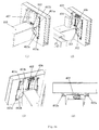
- Figs. 4A(1), (2), (3) and (4) show specific structure of the drive means 304 for the detector box of the wall stand of an embodiment of the present invention.
- the drive means comprises: at least two guide rails 401a, 401b fixed in parallel to the bottom surface of the detector box 103; at least two sliders 402a, 402b provided on the rotary bracket 302, the slider 402a slidably connected to the guide rail 401a and interlocked with each other, and the slider 402b slidably connected to the guide rail 401b and interlocked with each other; and a power supply means 407 for driving the sliders 402a and 402b to reciprocate on the guide rails 401a, 401b respectively, wherein the guide rail 401a is provided with stoppers 403a, 403b at two ends, and the guide rail 401b is provided with stoppers 403c, 403d at two ends.
- Figs. 4A(2), (3) and (4) further illustrate specific structure of the power supply means 407 from different angles.
- Said power supply means further includes an electric motor 406 fixed on the rotary bracket 302, a leading screw 404 fixed on the rotary bracket 302 and rotatable with the drive of the electric motor 406, and a nut 405 fixed on the bottom surface of the detector box and fitted around the leading screw.
- the electric motor 406 After the electric motor 406 is activated, the rotary bracket 302 remains stationary, and the electric motor 406 rotates the leading screw 404, such that the nut 405 moves in an axial direction of the leading screw 404; since the nut 405 is fixedly connected to the detector box 103, then the detector box 103 will also move in the axial direction of the leading screw 404.
- the axial direction of the leading screw 404 is arranged to be perpendicular to the axial direction of the rotary shaft 303, thus ensuring that the detector box 103 moves in a direction perpendicular to the axial direction of the rotary shaft 303.
- Fig. 4B shows the operating state of the wall stand in the present embodiment.
- Fig. 4B(1) shows a state where the wall stand is used alone. Since the driving means 304 is capable of moving the detector box 103 in a plane supported by the rotary bracket 302 in a direction perpendicular to the axial direction of the rotary shaft 303, the support arm 105 can be designed to be relatively short, when the wall stand is used independently.
- Fig. 4B(2) shows a state where the wall stand is used in association with the stretcher table 104.
- the drive means 304 drives the detector box 103 to a position right below the stretcher table 104, thereby ensuring alignment of a central axis of the stretcher table 104 with the overhead tube system 101.
- Fig. 4B(3) shows another mode for independent usage of the wall stand.
- the rotary bracket 302 and the detector box 103 are first rotated, via the rotary shaft 303, to a position parallel to the height direction of the column 102, and then the support arm 105 is moved in the height direction of the column 102.
- the movable distance of the detector box 103 in the vertical direction is increased by reason of the drive means 304; or, the column 102 can be designed to be shorter without decreasing the movable distance of the detector box 103 in the vertical direction.
- the wall stand in Embodiment 2 is further provided with a support arm drive means disposed between the column 102 and the support arm 105, said drive means being for driving said support arm 105, the rotary bracket 302, the rotary shaft 303, and the detector box 103 to move together in a direction perpendicular to the height direction of the column 102.
- Figs. 5A(1) and 5A(2) show a specific structure of the drive means from different perspectives.
- the drive means includes two driving compartments 500 and 501, two pairs of guide rails 502a, 502b and 503a, 503b, one side of the driving compartment 500 being provided in a direction perpendicular to the height direction of the column 102 and connected to the column and another side opposing to said side being provided with the driving compartment 501.
- the top and bottom surfaces of the driving compartment 500 are provided with one guide rail 502a, 502b respectively; one side of the driving compartment 501 for connecting to the support arm 105 is provided with one guide rail 503a, and the bottom surface of the driving compartment 501 is provided with one guide rail 503b.
- the driving compartment 501 is slidably engaged with the guide rails 502a, 502b provided on the top and bottom surfaces of the driving compartment 500, via slip connection members positioned on top and bottom surfaces of the driving compartment 501, such as grooves or sliders.
- the support arm 105 is slidably engaged with the guide rails 503a, 503b provided on the driving compartment 501, via slip connection members positioned on a side of the support arm for connecting the driving compartment 501 and on a bottom side of the support arm, such as grooves or sliders.
- Each guide rail is provided with a stopper at both ends.
- Fig. 5A(2) shows that the driving compartment 500 further includes an electric motor 506, a leading screw 504 rotatable with the drive of the electric motor, and a nut 505 fixed on the driving compartment 501 and fitted around the leading screw 504.
- the driver compartment 501 also includes an electric motor, a leading screw rotatable with the drive of the electric motor, and a nut fixed on the support arm 105 and fitted around the leading screw.
- one, or two or more driving compartments can be provided according to requirements of actual applications.
- each of the other driving compartments drives a respective slidably connected driving compartment, in a direction starting from the proximity of the column 102 and away from the column 102. Therefore, the movable range of the support arm can be flexibly designed.
- Fig. 5B shows an operating state of the wall stand disclosed by the present embodiment.
- the doctor When the present wall stand is used in association with a stretcher table and the doctor needs to move the patient to take a plurality of chest X-rays for mosaicking, the doctor no longer has to move the stretch table on which the patient lies.
- the doctor only first needs to take a chest X-ray of an area 507 at a position shown in Fig. 5B(1) .
- the stretcher table 104 is kept stationary, the support arm 105 and the detector box 103 are driven by the driving compartments 500, 501 to move in a direction perpendicular to the height direction of the column 102, and in the meantime, the overhead tube system 101 moves associatedly in a same direction, such that a different area 508 can be easily radiographed. Further, radiographs of the areas 507, 508 can be mosaicked.
Landscapes
- Health & Medical Sciences (AREA)
- Life Sciences & Earth Sciences (AREA)
- Engineering & Computer Science (AREA)
- Medical Informatics (AREA)
- Physics & Mathematics (AREA)
- Radiology & Medical Imaging (AREA)
- Surgery (AREA)
- Nuclear Medicine, Radiotherapy & Molecular Imaging (AREA)
- Optics & Photonics (AREA)
- Pathology (AREA)
- Biophysics (AREA)
- Biomedical Technology (AREA)
- Heart & Thoracic Surgery (AREA)
- Molecular Biology (AREA)
- High Energy & Nuclear Physics (AREA)
- Animal Behavior & Ethology (AREA)
- General Health & Medical Sciences (AREA)
- Public Health (AREA)
- Veterinary Medicine (AREA)
- General Engineering & Computer Science (AREA)
- Mechanical Engineering (AREA)
- General Physics & Mathematics (AREA)
- Apparatus For Radiation Diagnosis (AREA)
Claims (7)
- Wandstativ, umfassend: eine Säule (102), eine Detektorbox (103), einen Stützarm (105) für die Detektorbox, eine Drehwelle (303), die am Stützarm montiert ist, eine Drehhalterung (302) für die Detektorbox, die imstande ist, sich um die Drehwelle (303) zu drehen, wobei das Wandstativ des Weiteren ein Antriebsmittel (304) für die Detektorbox (103) umfasst, das imstande ist, die Detektorbox (103) in einer Ebene, gestützt durch die Drehhalterung (302), in einer Richtung senkrecht zu einer Achsrichtung der Drehwelle (303) zu bewegen; dadurch gekennzeichnet, dass das Wandstativ des Weiteren ein Stützarmantriebsmittel umfasst, das zwischen der Säule und dem Stützarm bereitgestellt ist, wobei das Stützarmantriebsmittel zum Antreiben des Stützarms (105), der Drehhalterung (302), der Drehwelle (303) und der Detektorbox (103) dient, um sich gemeinsam in eine Richtung senkrecht auf eine Höhenrichtung der Säule zu bewegen, und wobei das Stützarmantriebsmittel eine Antriebskammer (500) umfasst, wobei eine Seite der Antriebskammer mit der Säule in einer Richtung senkrecht zur Höhenrichtung der Säule verbunden ist, und wobei eine entgegengesetzte Seite davon mittels eines Gleitverbindungsbauteils gleitfähig mit dem Stützarm (105) verbunden ist.
- Wandstativ nach Anspruch 1, wobei das Antriebsmittel (304) für die Detektorbox (103) zumindest zwei parallele Führungsschienen (401a, 401b), die an einer Bodenfläche der Detektorbox (103) fixiert sind, zumindest zwei Schieber, die an die Drehhalterung fixiert und mit den Führungsschienen eingerastet sind, und ein Stromversorgungsmittel (407), das auf der Drehhalterung (302) bereitgestellt ist, umfasst.
- Wandstativ nach Anspruch 2, wobei das Stromversorgungsmittel (407) des Weiteren einen Elektromotor, eine Leitspindel, die drehbar mit dem Antrieb des Elektromotors verbunden ist, und eine Mutter, die an der Bodenfläche der Detektorbox fixiert und um die Leitspindel gesetzt ist, umfasst.
- Wandstativ nach einem der vorangehenden Anspruch, wobei das Stützarmantriebsmittel mehrere Antriebskammern (500, 501) umfasst, wobei eine Seite einer ersten Antriebskammer (500) mit der Säule in einer Richtung senkrecht zur Höhenrichtung der Säule verbunden ist und eine entgegengesetzte Seite davon mit einer zweiten Antriebskammer (501) bereitgestellt ist, wobei die zweite und erste Antriebskammer (500, 501) mittels eines Gleitverbindungbauteils verbunden sind, und wobei eine Seite einer am weitesten von der Säule entfernten Antriebskammer gleitfähig mit einer anderen angrenzenden Antriebskammer verbunden ist, und eine entgegengesetzte Seite davon mittels eines Gleitverbindungsbauteils gleitfähig mit dem Stützarm verbunden ist.
- Wandstativ nach einem vorangehenden Anspruch, wobei das Gleitverbindungsbauteil zumindest zwei Führungsschienen (502a, 502b, 503a, 503b) und einen Schieber, der entlang der Führungsschienen oder einer Vertiefung, die zu den Führungsschienen passt, gleitfähig ist, umfasst.
- Wandstativ nach einem vorangehenden Anspruch, wobei die Antriebskammer (500, 501) des Weiteren einen Elektromotor, eine Leitspindel, die mit dem Antrieb des Elektromotors drehbar ist, und eine Mutter, die an einem angetriebenen Objekt fixiert und um die Leitspindel gesetzt ist, umfasst.
- Wandstativ nach einem der vorangehenden Ansprüche, wobei jede Führungsschiene (401a, 401b) mit einem Stopper (403a, 403b, 403c, 403d) an beiden Enden bereitgestellt ist.
Applications Claiming Priority (1)
| Application Number | Priority Date | Filing Date | Title |
|---|---|---|---|
| CN201210031588.8A CN103222878B (zh) | 2012-01-30 | 2012-01-30 | 一种胸片架 |
Publications (2)
| Publication Number | Publication Date |
|---|---|
| EP2620101A1 EP2620101A1 (de) | 2013-07-31 |
| EP2620101B1 true EP2620101B1 (de) | 2016-08-03 |
Family
ID=47628012
Family Applications (1)
| Application Number | Title | Priority Date | Filing Date |
|---|---|---|---|
| EP13151916.7A Not-in-force EP2620101B1 (de) | 2012-01-30 | 2013-01-18 | Wandgestell |
Country Status (4)
| Country | Link |
|---|---|
| US (1) | US9200750B2 (de) |
| EP (1) | EP2620101B1 (de) |
| CN (1) | CN103222878B (de) |
| ES (1) | ES2592183T3 (de) |
Families Citing this family (5)
| Publication number | Priority date | Publication date | Assignee | Title |
|---|---|---|---|---|
| CN108113688B (zh) * | 2016-11-30 | 2023-07-04 | 通用电气公司 | 探测器支撑装置及x射线成像设备 |
| BR102020013650A2 (pt) * | 2020-07-02 | 2020-10-20 | Vmi Tecnologias Ltda | aparelho de raios-x com estátiva porta tubo/bucky ortogonal com braço articulado de rotação isocêntrica |
| US12364450B2 (en) * | 2021-05-07 | 2025-07-22 | Ryan Sotkovsky | Portable x-ray detector holder and positioner |
| CN115755297B (zh) * | 2022-11-11 | 2026-02-13 | 中国电信股份有限公司 | 排障辅助装置 |
| CN116412340B (zh) * | 2023-04-17 | 2025-08-22 | 深圳创维-Rgb电子有限公司 | 挂架及显示设备 |
Family Cites Families (7)
| Publication number | Priority date | Publication date | Assignee | Title |
|---|---|---|---|---|
| US6851851B2 (en) * | 1999-10-06 | 2005-02-08 | Hologic, Inc. | Digital flat panel x-ray receptor positioning in diagnostic radiology |
| US7165885B2 (en) * | 2002-12-06 | 2007-01-23 | Koninklijke Philips Electronics, N.V. | X-ray system |
| US7090396B2 (en) * | 2004-10-15 | 2006-08-15 | General Electric Company | Systems, methods and apparatus of a radiographic positioner |
| DE102005055653B4 (de) * | 2005-11-22 | 2025-10-09 | Siemens Healthineers Ag | Verfahren und Vorrichtung zur Röntgendiagnose eines Untersuchungsobjekts |
| CN201101534Y (zh) * | 2007-12-05 | 2008-08-20 | 刘志华 | 一种x线投照胸片架 |
| KR100920751B1 (ko) * | 2009-03-19 | 2009-10-07 | 동강의료기(주) | 3차원 촬영위치 선정을 위한 엑스선 촬영장치의 디지털 스탠드 |
| KR101105624B1 (ko) * | 2009-04-22 | 2012-01-18 | (주)신영포엠 | 자동위치조정이 가능한 x선디텍터를 갖는 의료용진단기기 |
-
2012
- 2012-01-30 CN CN201210031588.8A patent/CN103222878B/zh active Active
-
2013
- 2013-01-18 EP EP13151916.7A patent/EP2620101B1/de not_active Not-in-force
- 2013-01-18 ES ES13151916.7T patent/ES2592183T3/es active Active
- 2013-01-29 US US13/752,412 patent/US9200750B2/en active Active
Also Published As
| Publication number | Publication date |
|---|---|
| CN103222878A (zh) | 2013-07-31 |
| US20130193295A1 (en) | 2013-08-01 |
| US9200750B2 (en) | 2015-12-01 |
| ES2592183T3 (es) | 2016-11-28 |
| CN103222878B (zh) | 2017-03-01 |
| EP2620101A1 (de) | 2013-07-31 |
Similar Documents
| Publication | Publication Date | Title |
|---|---|---|
| EP2620101A1 (de) | Wandgestell | |
| US9089309B2 (en) | Multiplane medical imaging system | |
| US4358856A (en) | Multiaxial x-ray apparatus | |
| US5095501A (en) | X-ray image-pickup apparatus | |
| US20140177799A1 (en) | X-ray imaging apparatus | |
| US9737275B2 (en) | X-ray diagnostic apparatus | |
| EP2502561B1 (de) | Bogenförmige medizinische Abbildungsausrüstung | |
| US9801598B2 (en) | X-ray diagnostic apparatus and X-ray diagnostic method | |
| EP3715838A1 (de) | Fahrzeugmontiertes strahlungsprüfsystem | |
| US20170095219A1 (en) | Bed apparatus and x-ray computed tomography apparatus | |
| JP5510540B2 (ja) | X線透視撮影装置 | |
| US7556427B2 (en) | X-ray radiography apparatus and X-ray generator moving device | |
| US20190090830A1 (en) | Imaging system | |
| US9907522B2 (en) | Radiation diagnostic apparatus | |
| JP7395243B2 (ja) | X線診断装置 | |
| JP5091506B2 (ja) | X線診断装置 | |
| EP1746332A1 (de) | Tragvorrichtung für Fernsehkameras oder Filmkameras | |
| EP2095768A1 (de) | Medizinisches Diagnosegerät mit längenverstellbarer Armstruktur | |
| EP4512341B1 (de) | Schwimmender wiegenpatiententisch mit multimodaler bildgebungsfähigkeit | |
| US20260041387A1 (en) | Radiation Detection Device and Medical Imaging Equipment | |
| JP2011019816A (ja) | X線画像診断装置 | |
| JP6257927B2 (ja) | 診断装置 | |
| JP6329447B2 (ja) | 医用画像診断装置の寝台 | |
| JP2015204949A (ja) | X線診断装置及び検出器固定ユニット | |
| CN102048549A (zh) | 一种x射线摄影系统中的电动旋转自锁装置 |
Legal Events
| Date | Code | Title | Description |
|---|---|---|---|
| PUAI | Public reference made under article 153(3) epc to a published international application that has entered the european phase |
Free format text: ORIGINAL CODE: 0009012 |
|
| AK | Designated contracting states |
Kind code of ref document: A1 Designated state(s): AL AT BE BG CH CY CZ DE DK EE ES FI FR GB GR HR HU IE IS IT LI LT LU LV MC MK MT NL NO PL PT RO RS SE SI SK SM TR |
|
| AX | Request for extension of the european patent |
Extension state: BA ME |
|
| 17P | Request for examination filed |
Effective date: 20140131 |
|
| RBV | Designated contracting states (corrected) |
Designated state(s): AL AT BE BG CH CY CZ DE DK EE ES FI FR GB GR HR HU IE IS IT LI LT LU LV MC MK MT NL NO PL PT RO RS SE SI SK SM TR |
|
| GRAP | Despatch of communication of intention to grant a patent |
Free format text: ORIGINAL CODE: EPIDOSNIGR1 |
|
| INTG | Intention to grant announced |
Effective date: 20160324 |
|
| GRAS | Grant fee paid |
Free format text: ORIGINAL CODE: EPIDOSNIGR3 |
|
| GRAA | (expected) grant |
Free format text: ORIGINAL CODE: 0009210 |
|
| AK | Designated contracting states |
Kind code of ref document: B1 Designated state(s): AL AT BE BG CH CY CZ DE DK EE ES FI FR GB GR HR HU IE IS IT LI LT LU LV MC MK MT NL NO PL PT RO RS SE SI SK SM TR |
|
| REG | Reference to a national code |
Ref country code: GB Ref legal event code: FG4D |
|
| REG | Reference to a national code |
Ref country code: CH Ref legal event code: EP Ref country code: AT Ref legal event code: REF Ref document number: 816809 Country of ref document: AT Kind code of ref document: T Effective date: 20160815 |
|
| REG | Reference to a national code |
Ref country code: IE Ref legal event code: FG4D |
|
| REG | Reference to a national code |
Ref country code: DE Ref legal event code: R096 Ref document number: 602013009989 Country of ref document: DE |
|
| REG | Reference to a national code |
Ref country code: ES Ref legal event code: FG2A Ref document number: 2592183 Country of ref document: ES Kind code of ref document: T3 Effective date: 20161128 |
|
| REG | Reference to a national code |
Ref country code: NL Ref legal event code: MP Effective date: 20160803 |
|
| REG | Reference to a national code |
Ref country code: LT Ref legal event code: MG4D |
|
| REG | Reference to a national code |
Ref country code: AT Ref legal event code: MK05 Ref document number: 816809 Country of ref document: AT Kind code of ref document: T Effective date: 20160803 |
|
| REG | Reference to a national code |
Ref country code: FR Ref legal event code: PLFP Year of fee payment: 5 |
|
| PG25 | Lapsed in a contracting state [announced via postgrant information from national office to epo] |
Ref country code: NL Free format text: LAPSE BECAUSE OF FAILURE TO SUBMIT A TRANSLATION OF THE DESCRIPTION OR TO PAY THE FEE WITHIN THE PRESCRIBED TIME-LIMIT Effective date: 20160803 Ref country code: NO Free format text: LAPSE BECAUSE OF FAILURE TO SUBMIT A TRANSLATION OF THE DESCRIPTION OR TO PAY THE FEE WITHIN THE PRESCRIBED TIME-LIMIT Effective date: 20161103 Ref country code: HR Free format text: LAPSE BECAUSE OF FAILURE TO SUBMIT A TRANSLATION OF THE DESCRIPTION OR TO PAY THE FEE WITHIN THE PRESCRIBED TIME-LIMIT Effective date: 20160803 Ref country code: IS Free format text: LAPSE BECAUSE OF FAILURE TO SUBMIT A TRANSLATION OF THE DESCRIPTION OR TO PAY THE FEE WITHIN THE PRESCRIBED TIME-LIMIT Effective date: 20161203 Ref country code: LT Free format text: LAPSE BECAUSE OF FAILURE TO SUBMIT A TRANSLATION OF THE DESCRIPTION OR TO PAY THE FEE WITHIN THE PRESCRIBED TIME-LIMIT Effective date: 20160803 Ref country code: RS Free format text: LAPSE BECAUSE OF FAILURE TO SUBMIT A TRANSLATION OF THE DESCRIPTION OR TO PAY THE FEE WITHIN THE PRESCRIBED TIME-LIMIT Effective date: 20160803 Ref country code: FI Free format text: LAPSE BECAUSE OF FAILURE TO SUBMIT A TRANSLATION OF THE DESCRIPTION OR TO PAY THE FEE WITHIN THE PRESCRIBED TIME-LIMIT Effective date: 20160803 |
|
| PG25 | Lapsed in a contracting state [announced via postgrant information from national office to epo] |
Ref country code: PL Free format text: LAPSE BECAUSE OF FAILURE TO SUBMIT A TRANSLATION OF THE DESCRIPTION OR TO PAY THE FEE WITHIN THE PRESCRIBED TIME-LIMIT Effective date: 20160803 Ref country code: SE Free format text: LAPSE BECAUSE OF FAILURE TO SUBMIT A TRANSLATION OF THE DESCRIPTION OR TO PAY THE FEE WITHIN THE PRESCRIBED TIME-LIMIT Effective date: 20160803 Ref country code: GR Free format text: LAPSE BECAUSE OF FAILURE TO SUBMIT A TRANSLATION OF THE DESCRIPTION OR TO PAY THE FEE WITHIN THE PRESCRIBED TIME-LIMIT Effective date: 20161104 Ref country code: PT Free format text: LAPSE BECAUSE OF FAILURE TO SUBMIT A TRANSLATION OF THE DESCRIPTION OR TO PAY THE FEE WITHIN THE PRESCRIBED TIME-LIMIT Effective date: 20161205 Ref country code: LV Free format text: LAPSE BECAUSE OF FAILURE TO SUBMIT A TRANSLATION OF THE DESCRIPTION OR TO PAY THE FEE WITHIN THE PRESCRIBED TIME-LIMIT Effective date: 20160803 Ref country code: AT Free format text: LAPSE BECAUSE OF FAILURE TO SUBMIT A TRANSLATION OF THE DESCRIPTION OR TO PAY THE FEE WITHIN THE PRESCRIBED TIME-LIMIT Effective date: 20160803 |
|
| PG25 | Lapsed in a contracting state [announced via postgrant information from national office to epo] |
Ref country code: EE Free format text: LAPSE BECAUSE OF FAILURE TO SUBMIT A TRANSLATION OF THE DESCRIPTION OR TO PAY THE FEE WITHIN THE PRESCRIBED TIME-LIMIT Effective date: 20160803 Ref country code: RO Free format text: LAPSE BECAUSE OF FAILURE TO SUBMIT A TRANSLATION OF THE DESCRIPTION OR TO PAY THE FEE WITHIN THE PRESCRIBED TIME-LIMIT Effective date: 20160803 |
|
| REG | Reference to a national code |
Ref country code: DE Ref legal event code: R097 Ref document number: 602013009989 Country of ref document: DE |
|
| PG25 | Lapsed in a contracting state [announced via postgrant information from national office to epo] |
Ref country code: SM Free format text: LAPSE BECAUSE OF FAILURE TO SUBMIT A TRANSLATION OF THE DESCRIPTION OR TO PAY THE FEE WITHIN THE PRESCRIBED TIME-LIMIT Effective date: 20160803 Ref country code: BG Free format text: LAPSE BECAUSE OF FAILURE TO SUBMIT A TRANSLATION OF THE DESCRIPTION OR TO PAY THE FEE WITHIN THE PRESCRIBED TIME-LIMIT Effective date: 20161103 Ref country code: DK Free format text: LAPSE BECAUSE OF FAILURE TO SUBMIT A TRANSLATION OF THE DESCRIPTION OR TO PAY THE FEE WITHIN THE PRESCRIBED TIME-LIMIT Effective date: 20160803 Ref country code: CZ Free format text: LAPSE BECAUSE OF FAILURE TO SUBMIT A TRANSLATION OF THE DESCRIPTION OR TO PAY THE FEE WITHIN THE PRESCRIBED TIME-LIMIT Effective date: 20160803 Ref country code: BE Free format text: LAPSE BECAUSE OF FAILURE TO SUBMIT A TRANSLATION OF THE DESCRIPTION OR TO PAY THE FEE WITHIN THE PRESCRIBED TIME-LIMIT Effective date: 20160803 Ref country code: SK Free format text: LAPSE BECAUSE OF FAILURE TO SUBMIT A TRANSLATION OF THE DESCRIPTION OR TO PAY THE FEE WITHIN THE PRESCRIBED TIME-LIMIT Effective date: 20160803 |
|
| PLBE | No opposition filed within time limit |
Free format text: ORIGINAL CODE: 0009261 |
|
| STAA | Information on the status of an ep patent application or granted ep patent |
Free format text: STATUS: NO OPPOSITION FILED WITHIN TIME LIMIT |
|
| 26N | No opposition filed |
Effective date: 20170504 |
|
| REG | Reference to a national code |
Ref country code: DE Ref legal event code: R119 Ref document number: 602013009989 Country of ref document: DE |
|
| PG25 | Lapsed in a contracting state [announced via postgrant information from national office to epo] |
Ref country code: SI Free format text: LAPSE BECAUSE OF FAILURE TO SUBMIT A TRANSLATION OF THE DESCRIPTION OR TO PAY THE FEE WITHIN THE PRESCRIBED TIME-LIMIT Effective date: 20160803 |
|
| REG | Reference to a national code |
Ref country code: CH Ref legal event code: PL |
|
| PG25 | Lapsed in a contracting state [announced via postgrant information from national office to epo] |
Ref country code: MC Free format text: LAPSE BECAUSE OF FAILURE TO SUBMIT A TRANSLATION OF THE DESCRIPTION OR TO PAY THE FEE WITHIN THE PRESCRIBED TIME-LIMIT Effective date: 20160803 |
|
| PG25 | Lapsed in a contracting state [announced via postgrant information from national office to epo] |
Ref country code: LI Free format text: LAPSE BECAUSE OF NON-PAYMENT OF DUE FEES Effective date: 20170131 Ref country code: CH Free format text: LAPSE BECAUSE OF NON-PAYMENT OF DUE FEES Effective date: 20170131 |
|
| REG | Reference to a national code |
Ref country code: IE Ref legal event code: MM4A |
|
| PG25 | Lapsed in a contracting state [announced via postgrant information from national office to epo] |
Ref country code: DE Free format text: LAPSE BECAUSE OF NON-PAYMENT OF DUE FEES Effective date: 20170801 Ref country code: LU Free format text: LAPSE BECAUSE OF NON-PAYMENT OF DUE FEES Effective date: 20170118 |
|
| REG | Reference to a national code |
Ref country code: FR Ref legal event code: PLFP Year of fee payment: 6 |
|
| PG25 | Lapsed in a contracting state [announced via postgrant information from national office to epo] |
Ref country code: IE Free format text: LAPSE BECAUSE OF NON-PAYMENT OF DUE FEES Effective date: 20170118 |
|
| PG25 | Lapsed in a contracting state [announced via postgrant information from national office to epo] |
Ref country code: MT Free format text: LAPSE BECAUSE OF NON-PAYMENT OF DUE FEES Effective date: 20170118 |
|
| PG25 | Lapsed in a contracting state [announced via postgrant information from national office to epo] |
Ref country code: AL Free format text: LAPSE BECAUSE OF FAILURE TO SUBMIT A TRANSLATION OF THE DESCRIPTION OR TO PAY THE FEE WITHIN THE PRESCRIBED TIME-LIMIT Effective date: 20160803 |
|
| PG25 | Lapsed in a contracting state [announced via postgrant information from national office to epo] |
Ref country code: HU Free format text: LAPSE BECAUSE OF FAILURE TO SUBMIT A TRANSLATION OF THE DESCRIPTION OR TO PAY THE FEE WITHIN THE PRESCRIBED TIME-LIMIT; INVALID AB INITIO Effective date: 20130118 |
|
| PG25 | Lapsed in a contracting state [announced via postgrant information from national office to epo] |
Ref country code: CY Free format text: LAPSE BECAUSE OF NON-PAYMENT OF DUE FEES Effective date: 20160803 |
|
| PG25 | Lapsed in a contracting state [announced via postgrant information from national office to epo] |
Ref country code: MK Free format text: LAPSE BECAUSE OF FAILURE TO SUBMIT A TRANSLATION OF THE DESCRIPTION OR TO PAY THE FEE WITHIN THE PRESCRIBED TIME-LIMIT Effective date: 20160803 |
|
| PG25 | Lapsed in a contracting state [announced via postgrant information from national office to epo] |
Ref country code: TR Free format text: LAPSE BECAUSE OF FAILURE TO SUBMIT A TRANSLATION OF THE DESCRIPTION OR TO PAY THE FEE WITHIN THE PRESCRIBED TIME-LIMIT Effective date: 20160803 |
|
| PGFP | Annual fee paid to national office [announced via postgrant information from national office to epo] |
Ref country code: GB Payment date: 20201218 Year of fee payment: 9 Ref country code: FR Payment date: 20201217 Year of fee payment: 9 |
|
| PGFP | Annual fee paid to national office [announced via postgrant information from national office to epo] |
Ref country code: IT Payment date: 20210104 Year of fee payment: 9 |
|
| PGFP | Annual fee paid to national office [announced via postgrant information from national office to epo] |
Ref country code: ES Payment date: 20210201 Year of fee payment: 9 |
|
| GBPC | Gb: european patent ceased through non-payment of renewal fee |
Effective date: 20220118 |
|
| PG25 | Lapsed in a contracting state [announced via postgrant information from national office to epo] |
Ref country code: GB Free format text: LAPSE BECAUSE OF NON-PAYMENT OF DUE FEES Effective date: 20220118 |
|
| PG25 | Lapsed in a contracting state [announced via postgrant information from national office to epo] |
Ref country code: FR Free format text: LAPSE BECAUSE OF NON-PAYMENT OF DUE FEES Effective date: 20220131 |
|
| PG25 | Lapsed in a contracting state [announced via postgrant information from national office to epo] |
Ref country code: IT Free format text: LAPSE BECAUSE OF NON-PAYMENT OF DUE FEES Effective date: 20220118 |
|
| REG | Reference to a national code |
Ref country code: ES Ref legal event code: FD2A Effective date: 20230405 |
|
| PG25 | Lapsed in a contracting state [announced via postgrant information from national office to epo] |
Ref country code: ES Free format text: LAPSE BECAUSE OF NON-PAYMENT OF DUE FEES Effective date: 20220119 |