EP2619889B1 - Linear actuator - Google Patents
Linear actuator Download PDFInfo
- Publication number
- EP2619889B1 EP2619889B1 EP11827595.7A EP11827595A EP2619889B1 EP 2619889 B1 EP2619889 B1 EP 2619889B1 EP 11827595 A EP11827595 A EP 11827595A EP 2619889 B1 EP2619889 B1 EP 2619889B1
- Authority
- EP
- European Patent Office
- Prior art keywords
- linear actuator
- tube
- cover
- nut
- lead screw
- Prior art date
- Legal status (The legal status is an assumption and is not a legal conclusion. Google has not performed a legal analysis and makes no representation as to the accuracy of the status listed.)
- Not-in-force
Links
- 230000033001 locomotion Effects 0.000 claims description 13
- 239000004033 plastic Substances 0.000 claims description 3
- 230000005540 biological transmission Effects 0.000 description 7
- 238000000034 method Methods 0.000 description 5
- 230000009467 reduction Effects 0.000 description 5
- 239000000463 material Substances 0.000 description 4
- 238000010276 construction Methods 0.000 description 3
- 238000001125 extrusion Methods 0.000 description 3
- 230000008569 process Effects 0.000 description 3
- CRCBRZBVCDKPGA-UHFFFAOYSA-N 1,2,5-trichloro-3-(2,5-dichlorophenyl)benzene Chemical compound ClC1=CC=C(Cl)C(C=2C(=C(Cl)C=C(Cl)C=2)Cl)=C1 CRCBRZBVCDKPGA-UHFFFAOYSA-N 0.000 description 2
- 239000000853 adhesive Substances 0.000 description 2
- 230000001070 adhesive effect Effects 0.000 description 2
- 230000008901 benefit Effects 0.000 description 2
- 238000002788 crimping Methods 0.000 description 2
- 230000001419 dependent effect Effects 0.000 description 2
- 230000007246 mechanism Effects 0.000 description 2
- 230000002441 reversible effect Effects 0.000 description 2
- 229910001220 stainless steel Inorganic materials 0.000 description 2
- 239000010935 stainless steel Substances 0.000 description 2
- 230000004913 activation Effects 0.000 description 1
- 239000000356 contaminant Substances 0.000 description 1
- 238000011109 contamination Methods 0.000 description 1
- 238000005260 corrosion Methods 0.000 description 1
- 230000007797 corrosion Effects 0.000 description 1
- 230000013011 mating Effects 0.000 description 1
- 230000002265 prevention Effects 0.000 description 1
- 238000005070 sampling Methods 0.000 description 1
- 239000000758 substrate Substances 0.000 description 1
- 230000000153 supplemental effect Effects 0.000 description 1
Images


Classifications
-
- F—MECHANICAL ENGINEERING; LIGHTING; HEATING; WEAPONS; BLASTING
- F16—ENGINEERING ELEMENTS AND UNITS; GENERAL MEASURES FOR PRODUCING AND MAINTAINING EFFECTIVE FUNCTIONING OF MACHINES OR INSTALLATIONS; THERMAL INSULATION IN GENERAL
- F16H—GEARING
- F16H25/00—Gearings comprising primarily only cams, cam-followers and screw-and-nut mechanisms
- F16H25/08—Gearings comprising primarily only cams, cam-followers and screw-and-nut mechanisms for interconverting rotary motion and reciprocating motion
- F16H25/12—Gearings comprising primarily only cams, cam-followers and screw-and-nut mechanisms for interconverting rotary motion and reciprocating motion with reciprocation along the axis of rotation, e.g. gearings with helical grooves and automatic reversal
-
- F—MECHANICAL ENGINEERING; LIGHTING; HEATING; WEAPONS; BLASTING
- F16—ENGINEERING ELEMENTS AND UNITS; GENERAL MEASURES FOR PRODUCING AND MAINTAINING EFFECTIVE FUNCTIONING OF MACHINES OR INSTALLATIONS; THERMAL INSULATION IN GENERAL
- F16H—GEARING
- F16H25/00—Gearings comprising primarily only cams, cam-followers and screw-and-nut mechanisms
- F16H25/18—Gearings comprising primarily only cams, cam-followers and screw-and-nut mechanisms for conveying or interconverting oscillating or reciprocating motions
- F16H25/20—Screw mechanisms
-
- H—ELECTRICITY
- H02—GENERATION; CONVERSION OR DISTRIBUTION OF ELECTRIC POWER
- H02K—DYNAMO-ELECTRIC MACHINES
- H02K7/00—Arrangements for handling mechanical energy structurally associated with dynamo-electric machines, e.g. structural association with mechanical driving motors or auxiliary dynamo-electric machines
- H02K7/06—Means for converting reciprocating motion into rotary motion or vice versa
-
- F—MECHANICAL ENGINEERING; LIGHTING; HEATING; WEAPONS; BLASTING
- F16—ENGINEERING ELEMENTS AND UNITS; GENERAL MEASURES FOR PRODUCING AND MAINTAINING EFFECTIVE FUNCTIONING OF MACHINES OR INSTALLATIONS; THERMAL INSULATION IN GENERAL
- F16H—GEARING
- F16H25/00—Gearings comprising primarily only cams, cam-followers and screw-and-nut mechanisms
- F16H25/18—Gearings comprising primarily only cams, cam-followers and screw-and-nut mechanisms for conveying or interconverting oscillating or reciprocating motions
- F16H25/20—Screw mechanisms
- F16H2025/2031—Actuator casings
-
- F—MECHANICAL ENGINEERING; LIGHTING; HEATING; WEAPONS; BLASTING
- F16—ENGINEERING ELEMENTS AND UNITS; GENERAL MEASURES FOR PRODUCING AND MAINTAINING EFFECTIVE FUNCTIONING OF MACHINES OR INSTALLATIONS; THERMAL INSULATION IN GENERAL
- F16H—GEARING
- F16H25/00—Gearings comprising primarily only cams, cam-followers and screw-and-nut mechanisms
- F16H25/18—Gearings comprising primarily only cams, cam-followers and screw-and-nut mechanisms for conveying or interconverting oscillating or reciprocating motions
- F16H25/20—Screw mechanisms
- F16H2025/2062—Arrangements for driving the actuator
- F16H2025/2081—Parallel arrangement of drive motor to screw axis
-
- F—MECHANICAL ENGINEERING; LIGHTING; HEATING; WEAPONS; BLASTING
- F16—ENGINEERING ELEMENTS AND UNITS; GENERAL MEASURES FOR PRODUCING AND MAINTAINING EFFECTIVE FUNCTIONING OF MACHINES OR INSTALLATIONS; THERMAL INSULATION IN GENERAL
- F16H—GEARING
- F16H25/00—Gearings comprising primarily only cams, cam-followers and screw-and-nut mechanisms
- F16H25/18—Gearings comprising primarily only cams, cam-followers and screw-and-nut mechanisms for conveying or interconverting oscillating or reciprocating motions
- F16H25/20—Screw mechanisms
- F16H2025/2062—Arrangements for driving the actuator
- F16H2025/209—Arrangements for driving the actuator using worm gears
-
- F—MECHANICAL ENGINEERING; LIGHTING; HEATING; WEAPONS; BLASTING
- F16—ENGINEERING ELEMENTS AND UNITS; GENERAL MEASURES FOR PRODUCING AND MAINTAINING EFFECTIVE FUNCTIONING OF MACHINES OR INSTALLATIONS; THERMAL INSULATION IN GENERAL
- F16H—GEARING
- F16H25/00—Gearings comprising primarily only cams, cam-followers and screw-and-nut mechanisms
- F16H25/18—Gearings comprising primarily only cams, cam-followers and screw-and-nut mechanisms for conveying or interconverting oscillating or reciprocating motions
- F16H25/20—Screw mechanisms
- F16H2025/2062—Arrangements for driving the actuator
- F16H2025/2093—Arrangements for driving the actuator using conical gears
-
- H—ELECTRICITY
- H02—GENERATION; CONVERSION OR DISTRIBUTION OF ELECTRIC POWER
- H02K—DYNAMO-ELECTRIC MACHINES
- H02K5/00—Casings; Enclosures; Supports
- H02K5/04—Casings or enclosures characterised by the shape, form or construction thereof
-
- Y—GENERAL TAGGING OF NEW TECHNOLOGICAL DEVELOPMENTS; GENERAL TAGGING OF CROSS-SECTIONAL TECHNOLOGIES SPANNING OVER SEVERAL SECTIONS OF THE IPC; TECHNICAL SUBJECTS COVERED BY FORMER USPC CROSS-REFERENCE ART COLLECTIONS [XRACs] AND DIGESTS
- Y10—TECHNICAL SUBJECTS COVERED BY FORMER USPC
- Y10T—TECHNICAL SUBJECTS COVERED BY FORMER US CLASSIFICATION
- Y10T74/00—Machine element or mechanism
- Y10T74/18—Mechanical movements
- Y10T74/18568—Reciprocating or oscillating to or from alternating rotary
- Y10T74/18576—Reciprocating or oscillating to or from alternating rotary including screw and nut
- Y10T74/18648—Carriage surrounding, guided by, and primarily supported by member other than screw [e.g., linear guide, etc.]
Definitions
- This invention relates in general to linear actuators that are adapted to cause linear reciprocating movement of a workpiece along a desired path.
- this invention relates to an improved structure for such a linear actuator that is relatively compact in size, inexpensive in construction, quiet in operation, and capable of handling relatively heavy loads.
- a linear actuator is a device that can be used to cause linear movement, typically reciprocating linear movement, of a workpiece along a desired path of movement.
- a typical linear actuator includes an electric motor having a rotatable output shaft. The output shaft of the electric motor is connected through a gear train to a nut and lead screw mechanism. Rotation of the output shaft of the electric motor causes corresponding rotation of the lead screw.
- the nut has an opening formed therethrough having an internal thread.
- the lead screw extends through the opening and has an external thread which cooperates with the internal thread formed on the nut.
- the nut is mounted on the lead screw in such a manner as to be restrained from rotating with the lead screw when the lead screw rotates. As a result, rotation of the lead screw causes linear movement of the nut axially along the lead screw. The direction of such axial movement of the nut (and the workpiece connected thereto) is dependent upon the direction of rotation of the lead screw.
- Linear actuators are widely used in a variety of applications ranging from small to heavy loads. To accommodate heavy loads, known linear actuator structures have been formed from relatively large and heavy metallic components. Consequently, many linear actuator structures currently in use are relatively heavy and expensive.
- Japanese Patent No. JP 2007 032772 discloses a linear actuator device, such that when a feed screw shaft is inserted and the main-body housing is rotated, a nut screwed on the feed screw shaft is put in a linear motion.
- a bearing supports the rear end of the feed-screw shaft and is supported by being caught between an annular wall of an end-housing and a plurality of holding pins provided in a projecting manner from the rear-end face of the main-body housing.
- 2007/169578 provides a linear actuator with a reversible electric motor, which drives a spindle via a reduction gear with several stages and an activation element connected with it.
- An overload clutch is arranged in connection with the first stage or one of the first stages in the reduction gear. This is advantageous in terms of structure and load. Greater flexibility is achieved in the construction of the structure, and the clutch is moreover not loaded so severely.
- European Patent Application No. 0 577 541 provides a linear actuator comprising a threaded spindle rotatable in either direction, a threaded bushing that drives an output rod and a reversible motor that drives the spindle via a power transmission.
- DE 100 39 900 provides a linear screw actuator having a worm that is set to the rotation center of a motor such that a worm gear meshes with a power transmission shaft to receive a motor power. Power is sent by a gear between the power transmission shaft and an output shaft having a screw shaft and a nut. A telescopic-motion prevention mechanism for preventing start of the output shaft downward is set to the power transmission shaft.
- This invention relates to an improved structure for a linear actuator that includes a housing.
- a cover tube is supported relative to the housing.
- a nut engages the cover tube so as to prevent rotation of the nut relative to the cover tube.
- a lead screw rotatably engages the nut, wherein rotation of the lead screw causes the nut to travel along the lead screw.
- a linear actuator indicated generally at 10, in accordance with this invention.
- the illustrated linear actuator 10 is an electromechanical actuator that is cost effective and suitable for use in applications where space is limited.
- the linear actuator 10 can be used in applications in the healthcare market, such as bath lifts, wheel chairs, and the like. It will be appreciated, however, that the linear actuator 10 may be used in any desired environment for any desired purpose.
- the illustrated linear actuator 10 includes a housing 11 that defines an internal region.
- the illustrated housing 11 includes a first cover 12 and a second cover 14.
- the housing 11 is adapted to seal internal components of the linear actuator 10 from external conditions and to prevent tampering with the internal components.
- the first and second covers 12 and 14 can be rigid plastic members that are brought into mating engagement to form a clamshell configuration and ultrasonically welded to one another.
- the housing 11 may also be configured to support the internal components without the need for additional mechanical fasteners, as will be explained below.
- the first and second covers 12 and 14 may define corresponding support features including, for example, inwardly extending tabs, support slots, opposing bores, and the like. It will be appreciated that the first and second covers 12 and 14 can be embodied as any structures to accomplish the functions described herein.
- the linear actuator 10 is illustrated with the second cover 14 removed from the housing 11 so as to illustrate the internal components thereof.
- the linear actuator 10 includes a motor 20 that is adapted to provide a source of rotational power, as will be explained below.
- the motor 20 may be any apparatus configured to provide a source of rotational power, but is preferably an electrically powered device.
- the motor 20 is mounted within the housing 11 by corresponding support tabs that can be integrally formed from the first and second covers 12 and 14.
- a pair of O-rings 22 can be located at opposite ends of the motor 20 and be positioned between the motor 20 and the support tabs for dampening of noise and vibration that can otherwise be transferred to the housing 11.
- the illustrated motor 20 includes an output shaft 24.
- the illustrated output shaft 24 is embodied as a threaded worm drive, the purpose of which will be explained below.
- a distal end of the output shaft 24 can be mounted for rotation to the first cover 12 by a bushing 26 which, in turn, is inserted into an O-ring 28 that is secured by the first cover 12. It will be appreciated that the motor 20 and the output shaft 24 can be configured in any manner to accomplish the purposes described herein and below.
- the illustrated output shaft 24 engages a worm gear 30 and rotates the worm gear 30 about a first pin 31.
- the illustrated first pin 31 has an axis that is generally perpendicular to an axis defined by the output shaft 24. This configuration allows a higher torque to be converted into linear motion, while also resolving resultant forces that act internally on the linear actuator 10. Accordingly, the first pin 31 can be secured to the housing 11 by a pair of opposing mounting bores defined by the first and second covers 12 and 14 (see for example Fig. 5 ).
- An input gear 32 is also mounted on the first pin 31 and is connected to the worm gear 30 for rotation therewith.
- the first pin 31 may include a bushing 33 (see Fig. 4 ) or any other bearing structure for rotatably mounting the worm gear 30 and input gear 32 thereto.
- An output gear 34 is mounted on a second pin 35 for engagement with the input gear 32.
- the input gear 32 and the output gear 34 can be configured as any types of gear structure, such as for example spur gears or helical gears. Thus, it should be apparent that the output gear 34 is rotated in an opposite direction relative to the input gear 32.
- the second pin 35 can be generally parallel with the first pin 31 and, similarly, may be secured to the housing 11 by a pair of opposing mounting bores defined by the first and second covers 12 and 14 (see for example Fig. 5 ).
- a drive gear 37 may also be mounted on the second pin 35 and connected to the output gear 34 for rotation therewith.
- the second pin 35 may also include a bushing 36 or any other bearing structure for rotatably mounting the output gear 34 and drive gear 37 thereto.
- the illustrated linear actuator 10 also includes a driven gear 38 that meshes with the drive gear 37 for rotation therewith.
- the drive gear 37 and the driven gear 38 form a substantially right angle with one another and, therefore, can be embodied as suitable gear structures, such as bevel gears or miter gears.
- the linear actuator 10 also includes a thrust tube 40 that is supported by the housing 11.
- the illustrated thrust tube 40 defines a generally cylindrical portion having an open end.
- the open end of the thrust tube 40 can define an internally threaded surface 42, the purpose of which will be explained below.
- the illustrated thrust tube 40 also includes a plurality of openings that extend through side walls thereof.
- a lower portion of the worm gear 30 extends downwardly into an opening formed in a top surface of a thrust tube 40, respectively.
- the thrust tube 40 can include one or more support members 44 for engaging the first and second covers 12 and 14 to securely mount the thrust tube 40 within the housing 11.
- the thrust tube 40 can be configured in any manner for any desired application.
- an opposite end of the thrust tube 40 extends from the housing 11 through an aperture (not shown) that is defined by the first and second covers 12 and 14.
- the end portion of the thrust tube 40 defines a mounting portion that is configured to secure the linear actuator 10 to a separate component (not shown).
- the illustrated thrust tube 40 defines a bifurcated end having a thru-hole extending therethrough.
- the end portion of the thrust tube 40 may, however, be configured in any manner for any desired purpose.
- the linear actuator 10 is illustrated with additional internal components removed or shown in phantom.
- the linear actuator 10 also includes a lead screw 50.
- the illustrated lead screw 50 defines an elongated shaft that is supported for rotation within the housing 11.
- the lead screw 50 defines an external thread 52, the purpose of which will be explained below.
- the external thread 52 can have any angle, pitch, lead, depth or other dimensions as desired. It should be appreciated that the lead screw 50 can be configured in any manner for a desired application.
- a first end of the illustrated lead screw 50 extends into the open end of the thrust tube 40.
- a bearing assembly 54 can be inserted into the open end of the thrust tube 40 for rotatably supporting the lead screw 50 therein.
- the bearing assembly 54 can be embodied as any bearing structure, including for example a ball bearing assembly or the like.
- the illustrated driven gear 38 is mounted to the first end of the lead screw 50 using, for example, a splined connection or the like.
- operation of the motor 20 rotates the respective gears which results in rotation of the lead screw 50.
- a second end of the lead screw 50 includes a stop washer 55, an elastic bushing 56, a second washer 57, and a fastener 58.
- the elastic bushing 56 can be positioned between the stop washer 55 and the second washer 57.
- the fastener 58 can be secured to the end of the lead screw 50 for securing the components thereto.
- the illustrated linear actuator 10 also includes a nut 60 that is supported for axial movement along the outer surface of the lead screw 50.
- the nut 60 is an annular member that includes an internal thread 62.
- the internal thread 62 is configured to threadably engage the external thread 52 of the lead screw 50.
- the illustrated nut 60 also includes a flange portion 64.
- the flange portion 64 can be crimped or otherwise segmented to prevent rotation thereof as the lead screw 50 is rotated, as will be explained below.
- the illustrated linear actuator 10 also includes an extension tube 70.
- the illustrated extension tube 70 is a generally cylindrical member that defines openings at both ends.
- a first end of the extension tube 70 is secured to the nut 60.
- a portion of the nut 60 can be received within the first end of the extension tube 70.
- the nut 60 can be secured to the extension tube 70 by crimping the extension tube 70 around the nut 60.
- Such a connection can resolve both axial and radial loads between the extension tube 70 and the nut 60.
- the nut 60 can be secured to the extension tube 70 in any suitable manner, such as with a threaded connection for example.
- the extension tube 70 can be made from any desired material, such as stainless steel or the like, and can be formed using any suitable method, such as an extrusion process.
- the illustrated extension tube 70 includes an adapter 72 for mounting the linear actuator 10 to a separate component (not shown).
- the adapter 72 can be rigidly secured to the second end of the extension tube 70 by inserting a portion of the adaptor 72 therein (see Fig. 5 ).
- the adapter 72 can be secured to the extension tube 70 by crimping the extension tube 70 around the adapter 72. Such a connection can resolve both axial and radial loads between the extension tube 70 and the adapter 72.
- the adapter 72 can be secured to the extension tube 70 in any suitable manner, such as with a threaded connection for example.
- an opposite end of the adapter 72 extends from the extension tube 70 and defines a mounting portion that is configured to secure the linear actuator 10 to a separate component (not shown).
- the illustrated adapter 72 defines a bifurcated end having a thru-hole extending therethrough.
- the adapter 72 may, however, be configured in any manner for any desired purpose.
- the illustrated linear actuator 10 includes a cover tube 80.
- the illustrated cover tube 80 is a generally cylindrical member having openings at both ends. As shown, a first end of the cover tube 80 is connected to the thrust tube 40.
- the first end of the cover tube 80 may define an external threaded portion 82 that engages the internally threaded surface 42 of the thrust tube 40.
- the external threaded portion 82 can be restrained within the thrust tube 40 with an adhesive if so desired.
- the cover tube 80 can be secured to the thrust tube 40 in any manner.
- a second end of the cover tube 80 extends outwardly from the housing 11 through an aperture that is defined by the first and second covers 12 and 14.
- the cover tube 80 is supported by the housing 11 near the second end thereof, although such is not required.
- the cover tube 80 can be made from any desired material, such as stainless steel or the like, and can be formed using any suitable method, such as an extrusion process.
- the cover tube 80 may also include an internal spline portion 84.
- the internal spline portion 84 can include any number of axially extending protrusions or rails that extend along any length of the cover tube 80.
- the segmented flange portion 64 of the nut 60 corresponds with the internal spline portion 84 of the cover tube 80 (as shown in Fig. 8 ) so as to prevent rotation of the nut 60 relative to the cover tube 80.
- This configuration internally resolves torque that would otherwise be transferred from the rotating lead screw 60 to the housing 11.
- the internal spline portion 84 of the cover tube 80 can be integrally formed with the cover tube 80, such as with an extrusion process, or can be separate components that are attached thereto if so desired. It should be appreciated, however, that the cover tube 80 can be otherwise configured in any manner to prevent rotation of the nut 60 relative to the cover tube 80.
- the extension tube 70 is supported by the cover tube 80 for reciprocal movement relative thereto.
- rotation of the output shaft 24 of the motor 20 causes corresponding rotation of the lead screw 50.
- rotation of the lead screw 50 causes linear movement of the nut 60 axially along the lead screw 50.
- the extension tube 70 is mounted to the nut 60 and therefore reciprocates in a linear fashion relative to the cover tube 80, as indicated by the arrow X.
- the illustrated cover tube 80 also includes an annular seal 86.
- the illustrated seal 86 is secured to the second end of the cover tube 80. To accomplish this, a portion of the seal 86 may be press-fit into the cover tube 80 and secured therein by an annular groove or an adhesive. As best shown in Fig. 3 , the seal 86 is disposed between the cover tube 80 and the extension tube 70. Thus, as the extension tube 70 reciprocates in a linear fashion relative to the cover tube 80, the seal 86 wipes or otherwise cleans the outer surface of the extension tube 70 to prevent debris and other contaminants from entering the cover tube 80.
- the seal 86 may also be configured to provide supplemental support to the end of the extension tube 70.
- seal 86 can be configured in any manner to prevent contamination of the linear actuator 10 and provide support to the extension tube 70. Further, the seal 86 can be formed from any suitable material for accomplishing the functions described herein including, for example, rubber, plastic, or the like.
- the linear actuator 10 also includes a strain relief member 90, although such is not required.
- the strain relief member 90 can be embodied as a rubber grommet that is molded directly to a wire harness cable (not shown).
- the strain relief member 90 can be configured to seal associated opening in the housing 11 and to provide a strain relief so that the wire harness cable (not shown) cannot be pulled out of the linear actuator 10.
- the illustrated linear actuator 10 also includes a printed circuit board (PCB) 92, although such is not required.
- the PCB 92 is, in large measure, conventional in the art and may include an insulating substrate with various conductive traces. It should be appreciated that the PCB 92 can be any structure configured to support and electrically connect various electrical components (not shown) of the linear actuator 10.
- the illustrated linear actuator 10 also includes a non-contact feedback sensor 94 for providing operating data from the linear actuator 10, although such is not required.
- the non-contact feedback sensor 94 (such as a Bourns SD-5999 sensor) can be provided and driven off a gear reduction, such as the first gear reduction. A single gear reduction is used that will rotate the feedback sensor 94 approximately ten turns for the longest stroke actuator (500 mm).
- the feedback sensor 94 is programmable to provide the requested output (typically 0.5 to 4.5 VDC with a 5.0 VDC input) for the stroke required.
- This feedback sensor 94 can provide either analog or digital output.
- the programmability feature standardizes on a single component for analog output and a single component for digital output.
- the output of this device is programmable, a typical application would provide an output value of 0.5 VDC when the linear actuator 10 is in a retracted position and 4.5 VDC when the linear actuator 10 is in an extended position (based upon a 5.0 VDC input). In positions therebetween, the output is proportional to the stroke. For example, at 25% of stroke, the output would be 1.5 VDC; at 50% of stroke, the output would be 2.5 VDC; and at 75% of stroke, the output would be 3.5 VDC.
- This output can provide diagnostics through a controller (not shown). If the generated output is less than 0.5 VDC, the feedback circuit is shorted to ground; if the generated output is greater than 4.5 VDC, the feedback circuit is shorted to battery. In either case, it indicates a problem with the feedback and the controller will shut down the linear actuator 10.
- the linear actuator 10 may also include electronic limit switch control that provides end-of-stroke shut off and/or a mid-stroke thrust limiting control.
- the electronic limit switch design senses current of the motor 20 to control travel of the extension tube 70.
- the controller (not shown) cuts power to the motor 20 and stops the linear actuator 10 through relays (not shown). This power shut off occurs anytime the current threshold is exceeded, which occurs at ends-of-stroke positions or due to a mid-stroke overload.
- the current threshold is automatically set by the controller by sampling current during the first cycle of the linear actuator 10. The threshold is independent in both operating directions of the linear actuator 10.
- linear actuator 10 is designed and constructed of materials that are resistant to corrosion.
Landscapes
- Engineering & Computer Science (AREA)
- General Engineering & Computer Science (AREA)
- Mechanical Engineering (AREA)
- Power Engineering (AREA)
- Transmission Devices (AREA)
Description
- This application claims the benefit of United States Provisional Application No.
61/386,280 filed September 24, 2010 - This invention relates in general to linear actuators that are adapted to cause linear reciprocating movement of a workpiece along a desired path. In particular, this invention relates to an improved structure for such a linear actuator that is relatively compact in size, inexpensive in construction, quiet in operation, and capable of handling relatively heavy loads.
- A linear actuator is a device that can be used to cause linear movement, typically reciprocating linear movement, of a workpiece along a desired path of movement. A typical linear actuator includes an electric motor having a rotatable output shaft. The output shaft of the electric motor is connected through a gear train to a nut and lead screw mechanism. Rotation of the output shaft of the electric motor causes corresponding rotation of the lead screw. The nut has an opening formed therethrough having an internal thread. The lead screw extends through the opening and has an external thread which cooperates with the internal thread formed on the nut. The nut is mounted on the lead screw in such a manner as to be restrained from rotating with the lead screw when the lead screw rotates. As a result, rotation of the lead screw causes linear movement of the nut axially along the lead screw. The direction of such axial movement of the nut (and the workpiece connected thereto) is dependent upon the direction of rotation of the lead screw.
- Linear actuators are widely used in a variety of applications ranging from small to heavy loads. To accommodate heavy loads, known linear actuator structures have been formed from relatively large and heavy metallic components. Consequently, many linear actuator structures currently in use are relatively heavy and expensive. Japanese Patent No.
JP 2007 032772 U.S. Patent Publication No. 2007/169578 provides a linear actuator with a reversible electric motor, which drives a spindle via a reduction gear with several stages and an activation element connected with it. An overload clutch is arranged in connection with the first stage or one of the first stages in the reduction gear. This is advantageous in terms of structure and load. Greater flexibility is achieved in the construction of the structure, and the clutch is moreover not loaded so severely. European Patent Application No.0 577 541 provides a linear actuator comprising a threaded spindle rotatable in either direction, a threaded bushing that drives an output rod and a reversible motor that drives the spindle via a power transmission. In certain cases such as hospital beds it might be desired instantly to arrive at one or the other extreme position or an intermediate position from any position. This is achieved by disconnecting the power transmission from the spindle which is not of the self-locking type. In a gear transmission having a pair of bevel gears, the power transmission may be disconnected by pulling the gear on the drive shaft out of its engagement with the other pair of gears. The gear is axially displaceable along the drive shaft, but mutually locked in the rotation for instance by a driver unit or polygon. The construction offers the advantage of being instantly operational from the connected position. German Patent No.DE 100 39 900 provides a linear screw actuator having a worm that is set to the rotation center of a motor such that a worm gear meshes with a power transmission shaft to receive a motor power. Power is sent by a gear between the power transmission shaft and an output shaft having a screw shaft and a nut. A telescopic-motion prevention mechanism for preventing start of the output shaft downward is set to the power transmission shaft. Thus, it would be desirable to provide an improved linear actuator structure that is relatively lightweight and inexpensive to produce, and yet which is capable of handling relatively heavy loads. - This invention relates to an improved structure for a linear actuator that includes a housing. A cover tube is supported relative to the housing. A nut engages the cover tube so as to prevent rotation of the nut relative to the cover tube. A lead screw rotatably engages the nut, wherein rotation of the lead screw causes the nut to travel along the lead screw.
- Various aspects of this invention will become apparent to those skilled in the art from the following detailed description of the preferred embodiment, when read in light of the accompanying drawings.
-
-
Fig. 1 is a perspective view of a linear actuator in accordance with this invention. -
Fig. 2 is a perspective view of the linear actuator illustrated inFig. 1 , wherein an outer cover has been removed from the linear actuator. -
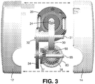
Fig. 3 is an exploded rear view of the linear actuator illustrated inFig. 2 , wherein various internal components have been removed. -
Fig. 4 is a perspective view of the linear actuator illustrated inFig. 2 , wherein additional internal components have been removed or are shown in phantom. -
Fig. 5 is a perspective view of the linear actuator illustrated inFig. 4 , wherein additional internal components have been removed or are shown in phantom. -
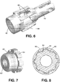
Fig. 6 is an enlarged perspective view of a thrust tube of the linear actuator illustrated inFig. 2 . -
Fig. 7 is an enlarged perspective view of a nut of the linear actuator illustrated inFig. 5 . -
Fig. 8 is a cross-sectional end view of the nut engaged with a cover tube of the linear actuator illustrated inFig. 4 . - Referring now to the drawings, there is illustrated in
Fig. 1 a linear actuator, indicated generally at 10, in accordance with this invention. The illustratedlinear actuator 10 is an electromechanical actuator that is cost effective and suitable for use in applications where space is limited. For example, thelinear actuator 10 can be used in applications in the healthcare market, such as bath lifts, wheel chairs, and the like. It will be appreciated, however, that thelinear actuator 10 may be used in any desired environment for any desired purpose. - The illustrated
linear actuator 10 includes ahousing 11 that defines an internal region. The illustratedhousing 11 includes afirst cover 12 and asecond cover 14. Thehousing 11 is adapted to seal internal components of thelinear actuator 10 from external conditions and to prevent tampering with the internal components. For example, the first andsecond covers housing 11 may also be configured to support the internal components without the need for additional mechanical fasteners, as will be explained below. Thus, the first andsecond covers second covers - Referring now to
Fig. 2 , thelinear actuator 10 is illustrated with thesecond cover 14 removed from thehousing 11 so as to illustrate the internal components thereof. As shown, thelinear actuator 10 includes amotor 20 that is adapted to provide a source of rotational power, as will be explained below. It will be appreciated that themotor 20 may be any apparatus configured to provide a source of rotational power, but is preferably an electrically powered device. As shown, themotor 20 is mounted within thehousing 11 by corresponding support tabs that can be integrally formed from the first and second covers 12 and 14. A pair of O-rings 22 (both O-rings 22 are shown inFig. 4 ) can be located at opposite ends of themotor 20 and be positioned between themotor 20 and the support tabs for dampening of noise and vibration that can otherwise be transferred to thehousing 11. - The illustrated
motor 20 includes anoutput shaft 24. The illustratedoutput shaft 24 is embodied as a threaded worm drive, the purpose of which will be explained below. A distal end of theoutput shaft 24 can be mounted for rotation to thefirst cover 12 by abushing 26 which, in turn, is inserted into an O-ring 28 that is secured by thefirst cover 12. It will be appreciated that themotor 20 and theoutput shaft 24 can be configured in any manner to accomplish the purposes described herein and below. - Referring now to
Figs. 2 and3 , the illustratedoutput shaft 24 engages aworm gear 30 and rotates theworm gear 30 about afirst pin 31. The illustratedfirst pin 31 has an axis that is generally perpendicular to an axis defined by theoutput shaft 24. This configuration allows a higher torque to be converted into linear motion, while also resolving resultant forces that act internally on thelinear actuator 10. Accordingly, thefirst pin 31 can be secured to thehousing 11 by a pair of opposing mounting bores defined by the first and second covers 12 and 14 (see for exampleFig. 5 ). Aninput gear 32 is also mounted on thefirst pin 31 and is connected to theworm gear 30 for rotation therewith. Thus, thefirst pin 31 may include a bushing 33 (seeFig. 4 ) or any other bearing structure for rotatably mounting theworm gear 30 andinput gear 32 thereto. - An
output gear 34 is mounted on asecond pin 35 for engagement with theinput gear 32. Theinput gear 32 and theoutput gear 34 can be configured as any types of gear structure, such as for example spur gears or helical gears. Thus, it should be apparent that theoutput gear 34 is rotated in an opposite direction relative to theinput gear 32. Thesecond pin 35 can be generally parallel with thefirst pin 31 and, similarly, may be secured to thehousing 11 by a pair of opposing mounting bores defined by the first and second covers 12 and 14 (see for exampleFig. 5 ). Adrive gear 37 may also be mounted on thesecond pin 35 and connected to theoutput gear 34 for rotation therewith. Thus, thesecond pin 35 may also include abushing 36 or any other bearing structure for rotatably mounting theoutput gear 34 and drivegear 37 thereto. - As shown in
Fig. 3 , the illustratedlinear actuator 10 also includes a drivengear 38 that meshes with thedrive gear 37 for rotation therewith. Thedrive gear 37 and the drivengear 38 form a substantially right angle with one another and, therefore, can be embodied as suitable gear structures, such as bevel gears or miter gears. - Referring now to
Figs. 2 and6 , thelinear actuator 10 also includes athrust tube 40 that is supported by thehousing 11. The illustratedthrust tube 40 defines a generally cylindrical portion having an open end. The open end of thethrust tube 40 can define an internally threadedsurface 42, the purpose of which will be explained below. The illustratedthrust tube 40 also includes a plurality of openings that extend through side walls thereof. As shown inFig. 2 , a lower portion of theworm gear 30 extends downwardly into an opening formed in a top surface of athrust tube 40, respectively. This configuration allows for thelinear actuator 10 to incorporate a desired gear ratio while also minimizing the amount of space occupied within the internal region of thehousing 11. Further, thethrust tube 40 can include one ormore support members 44 for engaging the first and second covers 12 and 14 to securely mount thethrust tube 40 within thehousing 11. Thethrust tube 40 can be configured in any manner for any desired application. - As shown, an opposite end of the
thrust tube 40 extends from thehousing 11 through an aperture (not shown) that is defined by the first and second covers 12 and 14. The end portion of thethrust tube 40 defines a mounting portion that is configured to secure thelinear actuator 10 to a separate component (not shown). For example, the illustratedthrust tube 40 defines a bifurcated end having a thru-hole extending therethrough. The end portion of thethrust tube 40 may, however, be configured in any manner for any desired purpose. - Referring now to
Figs. 4 and 5 , thelinear actuator 10 is illustrated with additional internal components removed or shown in phantom. As shown, thelinear actuator 10 also includes alead screw 50. The illustratedlead screw 50 defines an elongated shaft that is supported for rotation within thehousing 11. Thelead screw 50 defines anexternal thread 52, the purpose of which will be explained below. Theexternal thread 52 can have any angle, pitch, lead, depth or other dimensions as desired. It should be appreciated that thelead screw 50 can be configured in any manner for a desired application. - A first end of the illustrated
lead screw 50 extends into the open end of thethrust tube 40. As shown inFig. 5 , a bearingassembly 54 can be inserted into the open end of thethrust tube 40 for rotatably supporting thelead screw 50 therein. It should be appreciated that the bearingassembly 54 can be embodied as any bearing structure, including for example a ball bearing assembly or the like. The illustrated drivengear 38 is mounted to the first end of thelead screw 50 using, for example, a splined connection or the like. Thus, it should be appreciated that operation of themotor 20 rotates the respective gears which results in rotation of thelead screw 50. - A second end of the
lead screw 50 includes astop washer 55, anelastic bushing 56, asecond washer 57, and afastener 58. Theelastic bushing 56 can be positioned between thestop washer 55 and thesecond washer 57. Thefastener 58 can be secured to the end of thelead screw 50 for securing the components thereto. - The illustrated
linear actuator 10 also includes anut 60 that is supported for axial movement along the outer surface of thelead screw 50. As shown inFig. 7 , thenut 60 is an annular member that includes aninternal thread 62. Theinternal thread 62 is configured to threadably engage theexternal thread 52 of thelead screw 50. Thus, thenut 60 axially moves along thelead screw 50 as thelead screw 50 is rotated relative to thenut 60. The direction of such axial movement of thenut 60 is dependent upon the direction of rotation of thelead screw 50. The illustratednut 60 also includes aflange portion 64. Theflange portion 64 can be crimped or otherwise segmented to prevent rotation thereof as thelead screw 50 is rotated, as will be explained below. - Referring again to
Figs. 4 and 5 , the illustratedlinear actuator 10 also includes anextension tube 70. The illustratedextension tube 70 is a generally cylindrical member that defines openings at both ends. A first end of theextension tube 70 is secured to thenut 60. To accomplish this, a portion of thenut 60 can be received within the first end of theextension tube 70. Thenut 60 can be secured to theextension tube 70 by crimping theextension tube 70 around thenut 60. Such a connection can resolve both axial and radial loads between theextension tube 70 and thenut 60. Alternatively, thenut 60 can be secured to theextension tube 70 in any suitable manner, such as with a threaded connection for example. Further, theextension tube 70 can be made from any desired material, such as stainless steel or the like, and can be formed using any suitable method, such as an extrusion process. - The illustrated
extension tube 70 includes anadapter 72 for mounting thelinear actuator 10 to a separate component (not shown). Theadapter 72 can be rigidly secured to the second end of theextension tube 70 by inserting a portion of theadaptor 72 therein (seeFig. 5 ). Theadapter 72 can be secured to theextension tube 70 by crimping theextension tube 70 around theadapter 72. Such a connection can resolve both axial and radial loads between theextension tube 70 and theadapter 72. Alternatively, theadapter 72 can be secured to theextension tube 70 in any suitable manner, such as with a threaded connection for example. - As shown, an opposite end of the
adapter 72 extends from theextension tube 70 and defines a mounting portion that is configured to secure thelinear actuator 10 to a separate component (not shown). For example, the illustratedadapter 72 defines a bifurcated end having a thru-hole extending therethrough. Theadapter 72 may, however, be configured in any manner for any desired purpose. - Referring to
Figs. 2 through 4 , the illustratedlinear actuator 10 includes acover tube 80. The illustratedcover tube 80 is a generally cylindrical member having openings at both ends. As shown, a first end of thecover tube 80 is connected to thethrust tube 40. The first end of thecover tube 80 may define an external threadedportion 82 that engages the internally threadedsurface 42 of thethrust tube 40. The external threadedportion 82 can be restrained within thethrust tube 40 with an adhesive if so desired. Alternatively, thecover tube 80 can be secured to thethrust tube 40 in any manner. - A second end of the
cover tube 80 extends outwardly from thehousing 11 through an aperture that is defined by the first and second covers 12 and 14. Thecover tube 80 is supported by thehousing 11 near the second end thereof, although such is not required. Thecover tube 80 can be made from any desired material, such as stainless steel or the like, and can be formed using any suitable method, such as an extrusion process. - The
cover tube 80 may also include aninternal spline portion 84. Theinternal spline portion 84 can include any number of axially extending protrusions or rails that extend along any length of thecover tube 80. Thesegmented flange portion 64 of thenut 60 corresponds with theinternal spline portion 84 of the cover tube 80 (as shown inFig. 8 ) so as to prevent rotation of thenut 60 relative to thecover tube 80. This configuration internally resolves torque that would otherwise be transferred from therotating lead screw 60 to thehousing 11. Theinternal spline portion 84 of thecover tube 80 can be integrally formed with thecover tube 80, such as with an extrusion process, or can be separate components that are attached thereto if so desired. It should be appreciated, however, that thecover tube 80 can be otherwise configured in any manner to prevent rotation of thenut 60 relative to thecover tube 80. - As shown, the
extension tube 70 is supported by thecover tube 80 for reciprocal movement relative thereto. For example, rotation of theoutput shaft 24 of themotor 20 causes corresponding rotation of thelead screw 50. As a result, rotation of thelead screw 50 causes linear movement of thenut 60 axially along thelead screw 50. Theextension tube 70 is mounted to thenut 60 and therefore reciprocates in a linear fashion relative to thecover tube 80, as indicated by the arrow X. - The illustrated
cover tube 80 also includes anannular seal 86. The illustratedseal 86 is secured to the second end of thecover tube 80. To accomplish this, a portion of theseal 86 may be press-fit into thecover tube 80 and secured therein by an annular groove or an adhesive. As best shown inFig. 3 , theseal 86 is disposed between thecover tube 80 and theextension tube 70. Thus, as theextension tube 70 reciprocates in a linear fashion relative to thecover tube 80, theseal 86 wipes or otherwise cleans the outer surface of theextension tube 70 to prevent debris and other contaminants from entering thecover tube 80. Theseal 86 may also be configured to provide supplemental support to the end of theextension tube 70. It should be appreciated that theseal 86 can be configured in any manner to prevent contamination of thelinear actuator 10 and provide support to theextension tube 70. Further, theseal 86 can be formed from any suitable material for accomplishing the functions described herein including, for example, rubber, plastic, or the like. - Referring again to
Fig. 2 , thelinear actuator 10 also includes astrain relief member 90, although such is not required. Thestrain relief member 90 can be embodied as a rubber grommet that is molded directly to a wire harness cable (not shown). Thestrain relief member 90 can be configured to seal associated opening in thehousing 11 and to provide a strain relief so that the wire harness cable (not shown) cannot be pulled out of thelinear actuator 10. - The illustrated
linear actuator 10 also includes a printed circuit board (PCB) 92, although such is not required. ThePCB 92 is, in large measure, conventional in the art and may include an insulating substrate with various conductive traces. It should be appreciated that thePCB 92 can be any structure configured to support and electrically connect various electrical components (not shown) of thelinear actuator 10. - The illustrated
linear actuator 10 also includes anon-contact feedback sensor 94 for providing operating data from thelinear actuator 10, although such is not required. The non-contact feedback sensor 94 (such as a Bourns SD-5999 sensor) can be provided and driven off a gear reduction, such as the first gear reduction. A single gear reduction is used that will rotate thefeedback sensor 94 approximately ten turns for the longest stroke actuator (500 mm). Thefeedback sensor 94 is programmable to provide the requested output (typically 0.5 to 4.5 VDC with a 5.0 VDC input) for the stroke required. Thisfeedback sensor 94 can provide either analog or digital output. In addition to increased durability due to the non-contact design, the programmability feature standardizes on a single component for analog output and a single component for digital output. - While the output of this device is programmable, a typical application would provide an output value of 0.5 VDC when the
linear actuator 10 is in a retracted position and 4.5 VDC when thelinear actuator 10 is in an extended position (based upon a 5.0 VDC input). In positions therebetween, the output is proportional to the stroke. For example, at 25% of stroke, the output would be 1.5 VDC; at 50% of stroke, the output would be 2.5 VDC; and at 75% of stroke, the output would be 3.5 VDC. This output can provide diagnostics through a controller (not shown). If the generated output is less than 0.5 VDC, the feedback circuit is shorted to ground; if the generated output is greater than 4.5 VDC, the feedback circuit is shorted to battery. In either case, it indicates a problem with the feedback and the controller will shut down thelinear actuator 10. - The
linear actuator 10 may also include electronic limit switch control that provides end-of-stroke shut off and/or a mid-stroke thrust limiting control. The electronic limit switch design senses current of themotor 20 to control travel of theextension tube 70. When the preset current threshold is reached, the controller (not shown) cuts power to themotor 20 and stops thelinear actuator 10 through relays (not shown). This power shut off occurs anytime the current threshold is exceeded, which occurs at ends-of-stroke positions or due to a mid-stroke overload. The current threshold is automatically set by the controller by sampling current during the first cycle of thelinear actuator 10. The threshold is independent in both operating directions of thelinear actuator 10. - Further, it should be fully appreciated that the
linear actuator 10 is designed and constructed of materials that are resistant to corrosion. - The principle and mode of operation of this invention have been explained and illustrated in its preferred embodiment. However, it must be understood that this invention may be practiced otherwise than as specifically explained and illustrated without departing from its scope as defined in the appended claims.
Claims (11)
- A linear actuator (10) comprising:a housing (11);a motor (20) supported on the housing (11) and including an output shaft (24) that is rotatable about a first axis;a worm gear (30), wherein the output shaft (24) of the motor (20) rotates the worm gear (30) about a second axis that is generally perpendicular to the first axis;a lead screw (50), wherein the operation of the motor (20) is rotating the worm gear (30) to result in the rotation of the lead screw (50) about a third axis that is at a substantially right angle to the second axis, the lead screw (50) having an external thread (52);a cover tube (80) that is supported on the housing (11) and including an internal spline (84);a nut (60) having an internal thread (62) that cooperates with the external thread (52) of the lead screw (50) and an external flange portion (64) that cooperates with the internal spline (84) of the cover tube (80) such that rotation of the output shaft (24) of the motor (20) causes linear movement of the nut (60) relative to the cover tube (80); anda thrust tube (40) supported by the housing (11) and connected to the cover tube (80), characterized in that the thrust tube (40) includes a plurality of openings that extend through side walls thereof, and a lower portion of the worm gear (30) that extends downwardly into an opening formed in a top surface of the thrust tube (40).
- The linear actuator (10) of Claim 1 wherein the housing (11) has a support tab provided thereon, and the motor (20) is supported on the support tab.
- The linear actuator (10) of Claim 2 wherein a noise and vibration dampener is supported on the support tab, and the motor (20) is supported on the noise and vibration dampener.
- The linear actuator (10) of Claim 3 further including an input gear (32) that is connected for rotation with the worm gear (32) about the second axis.
- The linear actuator (10) of Claim 1 wherein an end portion of the lead screw (50) is rotatably supported by the thrust tube (40).
- The linear actuator (10) of Claim 1 wherein the cover tube (80) includes an internal spline (84) and wherein the nut (60) engages the internal spline (84) to prevent rotation of the nut (60) relative to the cover tube (80).
- The linear actuator (10) of Claim 6 wherein the nut (60) includes a segmented flange portion (64) that engages the internal spline (62) of the cover tube (80).
- The linear actuator (10) of Claim 1 wherein the housing (11) includes a first cover (12) and a second cover (14) that fit together to form a clamshell structure.
- The linear actuator (10) of Claim 8 wherein the first cover (12) and the second cover (14) are plastic components that are secured together by an ultrasonic weld.
- The linear actuator (10) of Claim 1 further including a non-contact feedback sensor (94) that is capable of providing operating data from the linear actuator (10) in either an analog output or a digital output.
- The linear actuator (10) of Claim 1 further including an electronic limit control switch that senses current from a motor (20) and provides one of an end-of-stroke shut off and a mid-stroke thrust shut off that is based on the sensed current.
Applications Claiming Priority (2)
| Application Number | Priority Date | Filing Date | Title |
|---|---|---|---|
| US38628010P | 2010-09-24 | 2010-09-24 | |
| PCT/US2011/052919 WO2012040556A2 (en) | 2010-09-24 | 2011-09-23 | Linear actuator |
Publications (3)
| Publication Number | Publication Date |
|---|---|
| EP2619889A2 EP2619889A2 (en) | 2013-07-31 |
| EP2619889A4 EP2619889A4 (en) | 2016-01-20 |
| EP2619889B1 true EP2619889B1 (en) | 2019-04-17 |
Family
ID=45874397
Family Applications (1)
| Application Number | Title | Priority Date | Filing Date |
|---|---|---|---|
| EP11827595.7A Not-in-force EP2619889B1 (en) | 2010-09-24 | 2011-09-23 | Linear actuator |
Country Status (7)
| Country | Link |
|---|---|
| US (1) | US9453563B2 (en) |
| EP (1) | EP2619889B1 (en) |
| CN (1) | CN103201935A (en) |
| CA (1) | CA2811939C (en) |
| DK (1) | DK2619889T3 (en) |
| MX (1) | MX2013003201A (en) |
| WO (1) | WO2012040556A2 (en) |
Families Citing this family (12)
| Publication number | Priority date | Publication date | Assignee | Title |
|---|---|---|---|---|
| DE102012211020B4 (en) * | 2012-06-27 | 2022-11-24 | Robert Bosch Gmbh | Adjustment drive with load compensation |
| CA2883085C (en) | 2012-12-20 | 2017-08-08 | Raytheon Company | Compensating drive nut assembly |
| TWM478082U (en) * | 2014-01-22 | 2014-05-11 | Timotion Technology Co Ltd | Linear actuating device |
| JP2015190618A (en) * | 2014-03-31 | 2015-11-02 | アイシン精機株式会社 | Rotation stop holding switching device |
| TWM535764U (en) * | 2016-08-12 | 2017-01-21 | Timotion Technology Co Ltd | Modular actuator |
| USD860278S1 (en) * | 2017-06-28 | 2019-09-17 | Linak A/S | Linear actuator and control box combination |
| US11855581B2 (en) * | 2017-07-18 | 2023-12-26 | Polar Racking Inc. | Solar panel support and drive system |
| TWM553079U (en) * | 2017-08-15 | 2017-12-11 | Timotion Technology Co Ltd | Electric cylinder structure having safety mechanism |
| GB2581800B (en) * | 2019-02-26 | 2023-08-09 | Reliance Rg Ltd | Linear actuator |
| DE102020118449A1 (en) * | 2020-07-13 | 2022-01-13 | Ewellix AB | Linear Actuator, Housing, Actuation System, and Assembly Method |
| CN113841324B (en) * | 2021-08-27 | 2025-03-11 | 焦旭 | A micro electric propulsion system and wearable device |
| CN115402506B (en) * | 2022-09-29 | 2025-03-21 | 四川腾盾科技有限公司 | A large unmanned aerial vehicle flap actuator and its mounting structure |
Citations (2)
| Publication number | Priority date | Publication date | Assignee | Title |
|---|---|---|---|---|
| EP0577541A1 (en) * | 1992-06-30 | 1994-01-05 | Linak A/S | Linear actuator |
| DE10039900A1 (en) * | 1999-10-14 | 2001-06-13 | Hiwin Mikrosystem Corp | Telescopic-motion stop type linear screw actuator has telescopic-motion prevention mechanism installed to power transmission shaft to prevent start of output shaft downward |
Family Cites Families (32)
| Publication number | Priority date | Publication date | Assignee | Title |
|---|---|---|---|---|
| CH652252A5 (en) * | 1981-07-13 | 1985-10-31 | Magnetic Elektromotoren Ag | Thrust and traction drive with an electric motor |
| US6101889A (en) * | 1998-01-20 | 2000-08-15 | Thomson Saginaw Ball Screw Company, Llc | Ball screw and nut linear actuator assemblies and methods of constructing and operating them |
| JPH11225457A (en) * | 1998-02-04 | 1999-08-17 | Smc Corp | Actuator |
| ATE301788T1 (en) * | 2000-10-03 | 2005-08-15 | Linak As | LINEAR ACTUATOR |
| JP2004218720A (en) * | 2003-01-14 | 2004-08-05 | Mitsuba Corp | Actuator |
| CN1922418B (en) * | 2004-02-24 | 2010-08-04 | 利纳克有限公司 | Linear actuator with overload clutch |
| AU2005293979B2 (en) * | 2004-10-15 | 2011-11-10 | Linak A/S | A linear actuator |
| JP4619229B2 (en) * | 2005-07-28 | 2011-01-26 | アスモ株式会社 | Linear actuator |
| JP5097551B2 (en) * | 2005-09-28 | 2012-12-12 | 株式会社ミツバ | Linear actuator |
| US8015889B2 (en) * | 2005-11-15 | 2011-09-13 | Honeywell International Inc. | Ballscrew with an integral high-efficiency thrust bearing |
| JP4709017B2 (en) * | 2006-01-12 | 2011-06-22 | ソニー株式会社 | Earphone device |
| CN101467334B (en) * | 2006-06-13 | 2012-08-29 | 利纳克有限公司 | Actuator |
| US8302227B2 (en) * | 2006-12-31 | 2012-11-06 | Linak A/S | Actuator system |
| US20080168852A1 (en) * | 2007-01-16 | 2008-07-17 | Hiwin Mikrosystem Corp. | Nut assembly for linear actuator leadscrew |
| JP5225599B2 (en) * | 2007-03-30 | 2013-07-03 | 株式会社ミツバ | Linear actuator for bed |
| WO2009015675A1 (en) * | 2007-08-01 | 2009-02-05 | Ab Skf | Linear actuator |
| ATE528543T1 (en) * | 2007-08-01 | 2011-10-15 | Skf Ab | LINEAR ACTUATOR |
| JP5243018B2 (en) * | 2007-12-27 | 2013-07-24 | Ntn株式会社 | Electric linear actuator |
| US9391490B2 (en) * | 2008-01-12 | 2016-07-12 | Linak A/S | Gear housing of linear actuator with opening for power take-off |
| DK2232101T3 (en) * | 2008-01-12 | 2013-02-11 | Linak As | Linear actuator |
| US20090249904A1 (en) * | 2008-04-06 | 2009-10-08 | Tung-Hsin Chen | Linear Actuator |
| TWI426685B (en) * | 2008-04-17 | 2014-02-11 | Smc Kk | Electric actuator |
| TWM356733U (en) * | 2008-12-05 | 2009-05-11 | Moteck Electric Corp | Push rod structure |
| WO2010092349A1 (en) * | 2009-02-16 | 2010-08-19 | Corcost Limited | Arrestor |
| US8156834B2 (en) * | 2009-03-18 | 2012-04-17 | Hiwin Mikrosystem Corp. | Linear actuator having quick-release mechanism |
| EP2499398B1 (en) * | 2009-11-13 | 2018-10-10 | Linak A/S | Linear actuator |
| JP5417588B2 (en) * | 2009-11-13 | 2014-02-19 | Smc株式会社 | Actuator |
| US8448540B2 (en) * | 2009-12-07 | 2013-05-28 | Hiwin Mikrosystem Corp. | Assembling mechanism of a self-locking linear actuator |
| US8701513B2 (en) * | 2010-07-14 | 2014-04-22 | Tol-O-Matic, Inc. | Screw driven linear actuator and housing assembly |
| US20120125399A1 (en) * | 2010-11-24 | 2012-05-24 | Kurt Schatz | Solar panel system |
| JP5497198B2 (en) * | 2010-12-09 | 2014-05-21 | 株式会社日立製作所 | Linear actuator |
| TWI458902B (en) * | 2012-05-02 | 2014-11-01 | Academia Sinica | Linear actuating module |
-
2011
- 2011-09-23 WO PCT/US2011/052919 patent/WO2012040556A2/en not_active Ceased
- 2011-09-23 MX MX2013003201A patent/MX2013003201A/en active IP Right Grant
- 2011-09-23 CA CA2811939A patent/CA2811939C/en not_active Expired - Fee Related
- 2011-09-23 CN CN2011800456146A patent/CN103201935A/en active Pending
- 2011-09-23 EP EP11827595.7A patent/EP2619889B1/en not_active Not-in-force
- 2011-09-23 DK DK11827595.7T patent/DK2619889T3/en active
- 2011-09-23 US US13/823,254 patent/US9453563B2/en active Active
Patent Citations (2)
| Publication number | Priority date | Publication date | Assignee | Title |
|---|---|---|---|---|
| EP0577541A1 (en) * | 1992-06-30 | 1994-01-05 | Linak A/S | Linear actuator |
| DE10039900A1 (en) * | 1999-10-14 | 2001-06-13 | Hiwin Mikrosystem Corp | Telescopic-motion stop type linear screw actuator has telescopic-motion prevention mechanism installed to power transmission shaft to prevent start of output shaft downward |
Also Published As
| Publication number | Publication date |
|---|---|
| EP2619889A2 (en) | 2013-07-31 |
| CA2811939A1 (en) | 2012-03-29 |
| WO2012040556A3 (en) | 2012-06-07 |
| WO2012040556A2 (en) | 2012-03-29 |
| US20130319148A1 (en) | 2013-12-05 |
| DK2619889T3 (en) | 2019-07-22 |
| MX2013003201A (en) | 2013-07-03 |
| CN103201935A (en) | 2013-07-10 |
| EP2619889A4 (en) | 2016-01-20 |
| US9453563B2 (en) | 2016-09-27 |
| CA2811939C (en) | 2018-10-16 |
Similar Documents
| Publication | Publication Date | Title |
|---|---|---|
| CA2811939C (en) | Linear actuator | |
| US5809833A (en) | Linear actuator | |
| CN102667247B (en) | Linear actuators | |
| US20050160846A1 (en) | Linear actuator | |
| CN102667246B (en) | Linear actuators | |
| EP1718885B1 (en) | A linear actuator comprising an overload clutch | |
| JP4808696B2 (en) | Hatch drive | |
| EP1101571B2 (en) | Linear actuator | |
| US6055877A (en) | Power seat track motor assembly | |
| US8001861B2 (en) | High force electro-mechanical actuator | |
| CA2841448A1 (en) | Limit switch assembly | |
| EP1783031B1 (en) | Electric automotive power steering with a belt-type transmission | |
| EP0681359A1 (en) | An electromechanical actuator having a supporting and containing housing | |
| EP3646446B1 (en) | Linear actuator | |
| JP2008019902A (en) | Linear motion actuator | |
| WO2004020870A1 (en) | Linear actuator and method of minimizing axial movement of the spindle | |
| JP5102715B2 (en) | Electric linear actuator and method for assembling the same | |
| DE10109185A1 (en) | Actuator drive has remotely controled coupling between drive motor and position detector, which produces signals for evaluation using emergency current supply if motor current not supplied | |
| CN217590487U (en) | Straight-stroke electric actuating mechanism | |
| JP2009121663A (en) | Actuator for electric valve | |
| CN215300387U (en) | Motor assembly for driving device of electric trunk cover and driving device comprising motor assembly | |
| JP2008095913A (en) | Electric actuator | |
| WO2023157751A1 (en) | Electric actuator | |
| JP2023141935A (en) | geared motor | |
| US20110283824A1 (en) | Actuator |
Legal Events
| Date | Code | Title | Description |
|---|---|---|---|
| PUAI | Public reference made under article 153(3) epc to a published international application that has entered the european phase |
Free format text: ORIGINAL CODE: 0009012 |
|
| 17P | Request for examination filed |
Effective date: 20130424 |
|
| AK | Designated contracting states |
Kind code of ref document: A2 Designated state(s): AL AT BE BG CH CY CZ DE DK EE ES FI FR GB GR HR HU IE IS IT LI LT LU LV MC MK MT NL NO PL PT RO RS SE SI SK SM TR |
|
| DAX | Request for extension of the european patent (deleted) | ||
| A4 | Supplementary search report drawn up and despatched |
Effective date: 20151217 |
|
| RIC1 | Information provided on ipc code assigned before grant |
Ipc: H02K 41/02 20060101AFI20151211BHEP |
|
| STAA | Information on the status of an ep patent application or granted ep patent |
Free format text: STATUS: EXAMINATION IS IN PROGRESS |
|
| 17Q | First examination report despatched |
Effective date: 20170530 |
|
| GRAP | Despatch of communication of intention to grant a patent |
Free format text: ORIGINAL CODE: EPIDOSNIGR1 |
|
| STAA | Information on the status of an ep patent application or granted ep patent |
Free format text: STATUS: GRANT OF PATENT IS INTENDED |
|
| INTG | Intention to grant announced |
Effective date: 20181126 |
|
| GRAS | Grant fee paid |
Free format text: ORIGINAL CODE: EPIDOSNIGR3 |
|
| GRAA | (expected) grant |
Free format text: ORIGINAL CODE: 0009210 |
|
| STAA | Information on the status of an ep patent application or granted ep patent |
Free format text: STATUS: THE PATENT HAS BEEN GRANTED |
|
| AK | Designated contracting states |
Kind code of ref document: B1 Designated state(s): AL AT BE BG CH CY CZ DE DK EE ES FI FR GB GR HR HU IE IS IT LI LT LU LV MC MK MT NL NO PL PT RO RS SE SI SK SM TR |
|
| REG | Reference to a national code |
Ref country code: GB Ref legal event code: FG4D |
|
| REG | Reference to a national code |
Ref country code: CH Ref legal event code: EP |
|
| REG | Reference to a national code |
Ref country code: DE Ref legal event code: R096 Ref document number: 602011058190 Country of ref document: DE |
|
| REG | Reference to a national code |
Ref country code: AT Ref legal event code: REF Ref document number: 1122637 Country of ref document: AT Kind code of ref document: T Effective date: 20190515 Ref country code: IE Ref legal event code: FG4D |
|
| REG | Reference to a national code |
Ref country code: SE Ref legal event code: TRGR |
|
| REG | Reference to a national code |
Ref country code: DE Ref legal event code: R082 Ref document number: 602011058190 Country of ref document: DE Representative=s name: HASELTINE LAKE KEMPNER LLP, DE Ref country code: DE Ref legal event code: R081 Ref document number: 602011058190 Country of ref document: DE Owner name: THOMSON INDUSTRIES, INC., MARENGO, US Free format text: FORMER OWNER: DANAHER CORPORATION, WOOD DALE, IL, US Ref country code: DE Ref legal event code: R082 Ref document number: 602011058190 Country of ref document: DE Representative=s name: HL KEMPNER PATENTANWALT, RECHTSANWALT, SOLICIT, DE |
|
| REG | Reference to a national code |
Ref country code: DK Ref legal event code: T3 Effective date: 20190718 |
|
| RAP2 | Party data changed (patent owner data changed or rights of a patent transferred) |
Owner name: THOMSON INDUSTRIES, INC. |
|
| REG | Reference to a national code |
Ref country code: NL Ref legal event code: MP Effective date: 20190417 Ref country code: BE Ref legal event code: PD Owner name: THOMSON INDUSTRIES, INC.; US Free format text: DETAILS ASSIGNMENT: CHANGE OF OWNER(S), CESSION; FORMER OWNER NAME: DANAHER CORPORATION Effective date: 20190703 |
|
| REG | Reference to a national code |
Ref country code: LT Ref legal event code: MG4D |
|
| PG25 | Lapsed in a contracting state [announced via postgrant information from national office to epo] |
Ref country code: NL Free format text: LAPSE BECAUSE OF FAILURE TO SUBMIT A TRANSLATION OF THE DESCRIPTION OR TO PAY THE FEE WITHIN THE PRESCRIBED TIME-LIMIT Effective date: 20190417 |
|
| REG | Reference to a national code |
Ref country code: GB Ref legal event code: 732E Free format text: REGISTERED BETWEEN 20190919 AND 20190925 |
|
| PG25 | Lapsed in a contracting state [announced via postgrant information from national office to epo] |
Ref country code: PT Free format text: LAPSE BECAUSE OF FAILURE TO SUBMIT A TRANSLATION OF THE DESCRIPTION OR TO PAY THE FEE WITHIN THE PRESCRIBED TIME-LIMIT Effective date: 20190817 Ref country code: AL Free format text: LAPSE BECAUSE OF FAILURE TO SUBMIT A TRANSLATION OF THE DESCRIPTION OR TO PAY THE FEE WITHIN THE PRESCRIBED TIME-LIMIT Effective date: 20190417 Ref country code: LT Free format text: LAPSE BECAUSE OF FAILURE TO SUBMIT A TRANSLATION OF THE DESCRIPTION OR TO PAY THE FEE WITHIN THE PRESCRIBED TIME-LIMIT Effective date: 20190417 Ref country code: ES Free format text: LAPSE BECAUSE OF FAILURE TO SUBMIT A TRANSLATION OF THE DESCRIPTION OR TO PAY THE FEE WITHIN THE PRESCRIBED TIME-LIMIT Effective date: 20190417 Ref country code: HR Free format text: LAPSE BECAUSE OF FAILURE TO SUBMIT A TRANSLATION OF THE DESCRIPTION OR TO PAY THE FEE WITHIN THE PRESCRIBED TIME-LIMIT Effective date: 20190417 Ref country code: FI Free format text: LAPSE BECAUSE OF FAILURE TO SUBMIT A TRANSLATION OF THE DESCRIPTION OR TO PAY THE FEE WITHIN THE PRESCRIBED TIME-LIMIT Effective date: 20190417 Ref country code: NO Free format text: LAPSE BECAUSE OF FAILURE TO SUBMIT A TRANSLATION OF THE DESCRIPTION OR TO PAY THE FEE WITHIN THE PRESCRIBED TIME-LIMIT Effective date: 20190717 |
|
| PGFP | Annual fee paid to national office [announced via postgrant information from national office to epo] |
Ref country code: DK Payment date: 20190927 Year of fee payment: 9 Ref country code: FR Payment date: 20190925 Year of fee payment: 9 Ref country code: IT Payment date: 20190920 Year of fee payment: 9 Ref country code: SE Payment date: 20190927 Year of fee payment: 9 |
|
| PG25 | Lapsed in a contracting state [announced via postgrant information from national office to epo] |
Ref country code: GR Free format text: LAPSE BECAUSE OF FAILURE TO SUBMIT A TRANSLATION OF THE DESCRIPTION OR TO PAY THE FEE WITHIN THE PRESCRIBED TIME-LIMIT Effective date: 20190718 Ref country code: PL Free format text: LAPSE BECAUSE OF FAILURE TO SUBMIT A TRANSLATION OF THE DESCRIPTION OR TO PAY THE FEE WITHIN THE PRESCRIBED TIME-LIMIT Effective date: 20190417 Ref country code: BG Free format text: LAPSE BECAUSE OF FAILURE TO SUBMIT A TRANSLATION OF THE DESCRIPTION OR TO PAY THE FEE WITHIN THE PRESCRIBED TIME-LIMIT Effective date: 20190717 Ref country code: LV Free format text: LAPSE BECAUSE OF FAILURE TO SUBMIT A TRANSLATION OF THE DESCRIPTION OR TO PAY THE FEE WITHIN THE PRESCRIBED TIME-LIMIT Effective date: 20190417 Ref country code: RS Free format text: LAPSE BECAUSE OF FAILURE TO SUBMIT A TRANSLATION OF THE DESCRIPTION OR TO PAY THE FEE WITHIN THE PRESCRIBED TIME-LIMIT Effective date: 20190417 |
|
| REG | Reference to a national code |
Ref country code: AT Ref legal event code: MK05 Ref document number: 1122637 Country of ref document: AT Kind code of ref document: T Effective date: 20190417 |
|
| PG25 | Lapsed in a contracting state [announced via postgrant information from national office to epo] |
Ref country code: IS Free format text: LAPSE BECAUSE OF FAILURE TO SUBMIT A TRANSLATION OF THE DESCRIPTION OR TO PAY THE FEE WITHIN THE PRESCRIBED TIME-LIMIT Effective date: 20190817 |
|
| PGFP | Annual fee paid to national office [announced via postgrant information from national office to epo] |
Ref country code: GB Payment date: 20190927 Year of fee payment: 9 |
|
| REG | Reference to a national code |
Ref country code: DE Ref legal event code: R097 Ref document number: 602011058190 Country of ref document: DE |
|
| PG25 | Lapsed in a contracting state [announced via postgrant information from national office to epo] |
Ref country code: EE Free format text: LAPSE BECAUSE OF FAILURE TO SUBMIT A TRANSLATION OF THE DESCRIPTION OR TO PAY THE FEE WITHIN THE PRESCRIBED TIME-LIMIT Effective date: 20190417 Ref country code: AT Free format text: LAPSE BECAUSE OF FAILURE TO SUBMIT A TRANSLATION OF THE DESCRIPTION OR TO PAY THE FEE WITHIN THE PRESCRIBED TIME-LIMIT Effective date: 20190417 Ref country code: SK Free format text: LAPSE BECAUSE OF FAILURE TO SUBMIT A TRANSLATION OF THE DESCRIPTION OR TO PAY THE FEE WITHIN THE PRESCRIBED TIME-LIMIT Effective date: 20190417 Ref country code: CZ Free format text: LAPSE BECAUSE OF FAILURE TO SUBMIT A TRANSLATION OF THE DESCRIPTION OR TO PAY THE FEE WITHIN THE PRESCRIBED TIME-LIMIT Effective date: 20190417 Ref country code: RO Free format text: LAPSE BECAUSE OF FAILURE TO SUBMIT A TRANSLATION OF THE DESCRIPTION OR TO PAY THE FEE WITHIN THE PRESCRIBED TIME-LIMIT Effective date: 20190417 |
|
| PGFP | Annual fee paid to national office [announced via postgrant information from national office to epo] |
Ref country code: DE Payment date: 20190927 Year of fee payment: 9 |
|
| PLBE | No opposition filed within time limit |
Free format text: ORIGINAL CODE: 0009261 |
|
| STAA | Information on the status of an ep patent application or granted ep patent |
Free format text: STATUS: NO OPPOSITION FILED WITHIN TIME LIMIT |
|
| PG25 | Lapsed in a contracting state [announced via postgrant information from national office to epo] |
Ref country code: SM Free format text: LAPSE BECAUSE OF FAILURE TO SUBMIT A TRANSLATION OF THE DESCRIPTION OR TO PAY THE FEE WITHIN THE PRESCRIBED TIME-LIMIT Effective date: 20190417 |
|
| PGFP | Annual fee paid to national office [announced via postgrant information from national office to epo] |
Ref country code: BE Payment date: 20190927 Year of fee payment: 9 |
|
| 26N | No opposition filed |
Effective date: 20200120 |
|
| PG25 | Lapsed in a contracting state [announced via postgrant information from national office to epo] |
Ref country code: TR Free format text: LAPSE BECAUSE OF FAILURE TO SUBMIT A TRANSLATION OF THE DESCRIPTION OR TO PAY THE FEE WITHIN THE PRESCRIBED TIME-LIMIT Effective date: 20190417 |
|
| PG25 | Lapsed in a contracting state [announced via postgrant information from national office to epo] |
Ref country code: SI Free format text: LAPSE BECAUSE OF FAILURE TO SUBMIT A TRANSLATION OF THE DESCRIPTION OR TO PAY THE FEE WITHIN THE PRESCRIBED TIME-LIMIT Effective date: 20190417 Ref country code: MC Free format text: LAPSE BECAUSE OF FAILURE TO SUBMIT A TRANSLATION OF THE DESCRIPTION OR TO PAY THE FEE WITHIN THE PRESCRIBED TIME-LIMIT Effective date: 20190417 |
|
| REG | Reference to a national code |
Ref country code: CH Ref legal event code: PL |
|
| PG25 | Lapsed in a contracting state [announced via postgrant information from national office to epo] |
Ref country code: LU Free format text: LAPSE BECAUSE OF NON-PAYMENT OF DUE FEES Effective date: 20190923 Ref country code: LI Free format text: LAPSE BECAUSE OF NON-PAYMENT OF DUE FEES Effective date: 20190930 Ref country code: IE Free format text: LAPSE BECAUSE OF NON-PAYMENT OF DUE FEES Effective date: 20190923 Ref country code: CH Free format text: LAPSE BECAUSE OF NON-PAYMENT OF DUE FEES Effective date: 20190930 |
|
| REG | Reference to a national code |
Ref country code: DE Ref legal event code: R082 Ref document number: 602011058190 Country of ref document: DE Representative=s name: HL KEMPNER PATENTANWALT, RECHTSANWALT, SOLICIT, DE |
|
| REG | Reference to a national code |
Ref country code: DE Ref legal event code: R119 Ref document number: 602011058190 Country of ref document: DE |
|
| REG | Reference to a national code |
Ref country code: DK Ref legal event code: EBP Effective date: 20200930 |
|
| GBPC | Gb: european patent ceased through non-payment of renewal fee |
Effective date: 20200923 |
|
| PG25 | Lapsed in a contracting state [announced via postgrant information from national office to epo] |
Ref country code: CY Free format text: LAPSE BECAUSE OF FAILURE TO SUBMIT A TRANSLATION OF THE DESCRIPTION OR TO PAY THE FEE WITHIN THE PRESCRIBED TIME-LIMIT Effective date: 20190417 |
|
| REG | Reference to a national code |
Ref country code: BE Ref legal event code: MM Effective date: 20200930 |
|
| PG25 | Lapsed in a contracting state [announced via postgrant information from national office to epo] |
Ref country code: MT Free format text: LAPSE BECAUSE OF FAILURE TO SUBMIT A TRANSLATION OF THE DESCRIPTION OR TO PAY THE FEE WITHIN THE PRESCRIBED TIME-LIMIT Effective date: 20190417 Ref country code: HU Free format text: LAPSE BECAUSE OF FAILURE TO SUBMIT A TRANSLATION OF THE DESCRIPTION OR TO PAY THE FEE WITHIN THE PRESCRIBED TIME-LIMIT; INVALID AB INITIO Effective date: 20110923 Ref country code: DE Free format text: LAPSE BECAUSE OF NON-PAYMENT OF DUE FEES Effective date: 20210401 Ref country code: FR Free format text: LAPSE BECAUSE OF NON-PAYMENT OF DUE FEES Effective date: 20200930 |
|
| PG25 | Lapsed in a contracting state [announced via postgrant information from national office to epo] |
Ref country code: BE Free format text: LAPSE BECAUSE OF NON-PAYMENT OF DUE FEES Effective date: 20200930 Ref country code: SE Free format text: LAPSE BECAUSE OF NON-PAYMENT OF DUE FEES Effective date: 20200924 Ref country code: GB Free format text: LAPSE BECAUSE OF NON-PAYMENT OF DUE FEES Effective date: 20200923 |
|
| REG | Reference to a national code |
Ref country code: SE Ref legal event code: EUG |
|
| PG25 | Lapsed in a contracting state [announced via postgrant information from national office to epo] |
Ref country code: IT Free format text: LAPSE BECAUSE OF NON-PAYMENT OF DUE FEES Effective date: 20200923 |
|
| PG25 | Lapsed in a contracting state [announced via postgrant information from national office to epo] |
Ref country code: DK Free format text: LAPSE BECAUSE OF NON-PAYMENT OF DUE FEES Effective date: 20200930 |
|
| PG25 | Lapsed in a contracting state [announced via postgrant information from national office to epo] |
Ref country code: MK Free format text: LAPSE BECAUSE OF FAILURE TO SUBMIT A TRANSLATION OF THE DESCRIPTION OR TO PAY THE FEE WITHIN THE PRESCRIBED TIME-LIMIT Effective date: 20190417 |