EP2499398B1 - Linear actuator - Google Patents
Linear actuator Download PDFInfo
- Publication number
- EP2499398B1 EP2499398B1 EP10800687.5A EP10800687A EP2499398B1 EP 2499398 B1 EP2499398 B1 EP 2499398B1 EP 10800687 A EP10800687 A EP 10800687A EP 2499398 B1 EP2499398 B1 EP 2499398B1
- Authority
- EP
- European Patent Office
- Prior art keywords
- spindle
- mounting
- housing
- outer tube
- console
- Prior art date
- Legal status (The legal status is an assumption and is not a legal conclusion. Google has not performed a legal analysis and makes no representation as to the accuracy of the status listed.)
- Active
Links
- 230000004913 activation Effects 0.000 claims description 27
- 230000005540 biological transmission Effects 0.000 claims description 13
- 230000002441 reversible effect Effects 0.000 claims description 5
- 230000000717 retained effect Effects 0.000 claims description 3
- 230000003213 activating effect Effects 0.000 claims description 2
- 239000004033 plastic Substances 0.000 description 8
- 229920003023 plastic Polymers 0.000 description 8
- 238000004519 manufacturing process Methods 0.000 description 5
- 238000010276 construction Methods 0.000 description 4
- 239000000463 material Substances 0.000 description 4
- XLYOFNOQVPJJNP-UHFFFAOYSA-N water Substances O XLYOFNOQVPJJNP-UHFFFAOYSA-N 0.000 description 4
- 238000007789 sealing Methods 0.000 description 3
- 229910001229 Pot metal Inorganic materials 0.000 description 2
- 239000004411 aluminium Substances 0.000 description 2
- 229910052782 aluminium Inorganic materials 0.000 description 2
- XAGFODPZIPBFFR-UHFFFAOYSA-N aluminium Chemical compound [Al] XAGFODPZIPBFFR-UHFFFAOYSA-N 0.000 description 2
- 230000001419 dependent effect Effects 0.000 description 2
- 229910052751 metal Inorganic materials 0.000 description 2
- 239000002184 metal Substances 0.000 description 2
- 238000007493 shaping process Methods 0.000 description 2
- 229910000897 Babbitt (metal) Inorganic materials 0.000 description 1
- 239000004677 Nylon Substances 0.000 description 1
- 239000004698 Polyethylene Substances 0.000 description 1
- 229910001297 Zn alloy Inorganic materials 0.000 description 1
- 230000008901 benefit Effects 0.000 description 1
- 230000006835 compression Effects 0.000 description 1
- 238000007906 compression Methods 0.000 description 1
- 230000008878 coupling Effects 0.000 description 1
- 238000010168 coupling process Methods 0.000 description 1
- 238000005859 coupling reaction Methods 0.000 description 1
- 238000006073 displacement reaction Methods 0.000 description 1
- 238000009826 distribution Methods 0.000 description 1
- 239000000428 dust Substances 0.000 description 1
- 238000004049 embossing Methods 0.000 description 1
- 238000005516 engineering process Methods 0.000 description 1
- 239000003365 glass fiber Substances 0.000 description 1
- 238000010348 incorporation Methods 0.000 description 1
- 238000003780 insertion Methods 0.000 description 1
- 230000037431 insertion Effects 0.000 description 1
- 238000000034 method Methods 0.000 description 1
- 230000007935 neutral effect Effects 0.000 description 1
- 230000000474 nursing effect Effects 0.000 description 1
- 229920001778 nylon Polymers 0.000 description 1
- 230000003287 optical effect Effects 0.000 description 1
- 230000035515 penetration Effects 0.000 description 1
- -1 polyethylene Polymers 0.000 description 1
- 229920000573 polyethylene Polymers 0.000 description 1
- 229920000915 polyvinyl chloride Polymers 0.000 description 1
- 239000004800 polyvinyl chloride Substances 0.000 description 1
- 230000008569 process Effects 0.000 description 1
- 239000010935 stainless steel Substances 0.000 description 1
- 229910001220 stainless steel Inorganic materials 0.000 description 1
- 238000005728 strengthening Methods 0.000 description 1
Images
Classifications
-
- H—ELECTRICITY
- H02—GENERATION; CONVERSION OR DISTRIBUTION OF ELECTRIC POWER
- H02K—DYNAMO-ELECTRIC MACHINES
- H02K7/00—Arrangements for handling mechanical energy structurally associated with dynamo-electric machines, e.g. structural association with mechanical driving motors or auxiliary dynamo-electric machines
- H02K7/06—Means for converting reciprocating motion into rotary motion or vice versa
-
- F—MECHANICAL ENGINEERING; LIGHTING; HEATING; WEAPONS; BLASTING
- F16—ENGINEERING ELEMENTS AND UNITS; GENERAL MEASURES FOR PRODUCING AND MAINTAINING EFFECTIVE FUNCTIONING OF MACHINES OR INSTALLATIONS; THERMAL INSULATION IN GENERAL
- F16H—GEARING
- F16H25/00—Gearings comprising primarily only cams, cam-followers and screw-and-nut mechanisms
- F16H25/18—Gearings comprising primarily only cams, cam-followers and screw-and-nut mechanisms for conveying or interconverting oscillating or reciprocating motions
- F16H25/20—Screw mechanisms
-
- H—ELECTRICITY
- H02—GENERATION; CONVERSION OR DISTRIBUTION OF ELECTRIC POWER
- H02K—DYNAMO-ELECTRIC MACHINES
- H02K11/00—Structural association of dynamo-electric machines with electric components or with devices for shielding, monitoring or protection
- H02K11/30—Structural association with control circuits or drive circuits
- H02K11/38—Control circuits or drive circuits associated with geared commutator motors of the worm-and-wheel type
-
- H—ELECTRICITY
- H02—GENERATION; CONVERSION OR DISTRIBUTION OF ELECTRIC POWER
- H02K—DYNAMO-ELECTRIC MACHINES
- H02K7/00—Arrangements for handling mechanical energy structurally associated with dynamo-electric machines, e.g. structural association with mechanical driving motors or auxiliary dynamo-electric machines
- H02K7/10—Structural association with clutches, brakes, gears, pulleys or mechanical starters
- H02K7/116—Structural association with clutches, brakes, gears, pulleys or mechanical starters with gears
- H02K7/1163—Structural association with clutches, brakes, gears, pulleys or mechanical starters with gears where at least two gears have non-parallel axes without having orbital motion
- H02K7/1166—Structural association with clutches, brakes, gears, pulleys or mechanical starters with gears where at least two gears have non-parallel axes without having orbital motion comprising worm and worm-wheel
-
- F—MECHANICAL ENGINEERING; LIGHTING; HEATING; WEAPONS; BLASTING
- F16—ENGINEERING ELEMENTS AND UNITS; GENERAL MEASURES FOR PRODUCING AND MAINTAINING EFFECTIVE FUNCTIONING OF MACHINES OR INSTALLATIONS; THERMAL INSULATION IN GENERAL
- F16H—GEARING
- F16H25/00—Gearings comprising primarily only cams, cam-followers and screw-and-nut mechanisms
- F16H25/18—Gearings comprising primarily only cams, cam-followers and screw-and-nut mechanisms for conveying or interconverting oscillating or reciprocating motions
- F16H25/20—Screw mechanisms
- F16H2025/2031—Actuator casings
-
- F—MECHANICAL ENGINEERING; LIGHTING; HEATING; WEAPONS; BLASTING
- F16—ENGINEERING ELEMENTS AND UNITS; GENERAL MEASURES FOR PRODUCING AND MAINTAINING EFFECTIVE FUNCTIONING OF MACHINES OR INSTALLATIONS; THERMAL INSULATION IN GENERAL
- F16H—GEARING
- F16H25/00—Gearings comprising primarily only cams, cam-followers and screw-and-nut mechanisms
- F16H25/18—Gearings comprising primarily only cams, cam-followers and screw-and-nut mechanisms for conveying or interconverting oscillating or reciprocating motions
- F16H25/20—Screw mechanisms
- F16H2025/2037—Actuator supports or means for fixing piston end, e.g. flanges
-
- F—MECHANICAL ENGINEERING; LIGHTING; HEATING; WEAPONS; BLASTING
- F16—ENGINEERING ELEMENTS AND UNITS; GENERAL MEASURES FOR PRODUCING AND MAINTAINING EFFECTIVE FUNCTIONING OF MACHINES OR INSTALLATIONS; THERMAL INSULATION IN GENERAL
- F16H—GEARING
- F16H25/00—Gearings comprising primarily only cams, cam-followers and screw-and-nut mechanisms
- F16H25/18—Gearings comprising primarily only cams, cam-followers and screw-and-nut mechanisms for conveying or interconverting oscillating or reciprocating motions
- F16H25/20—Screw mechanisms
- F16H2025/2062—Arrangements for driving the actuator
- F16H2025/2081—Parallel arrangement of drive motor to screw axis
-
- H—ELECTRICITY
- H02—GENERATION; CONVERSION OR DISTRIBUTION OF ELECTRIC POWER
- H02K—DYNAMO-ELECTRIC MACHINES
- H02K5/00—Casings; Enclosures; Supports
- H02K5/04—Casings or enclosures characterised by the shape, form or construction thereof
- H02K5/22—Auxiliary parts of casings not covered by groups H02K5/06-H02K5/20, e.g. shaped to form connection boxes or terminal boxes
- H02K5/225—Terminal boxes or connection arrangements
-
- Y—GENERAL TAGGING OF NEW TECHNOLOGICAL DEVELOPMENTS; GENERAL TAGGING OF CROSS-SECTIONAL TECHNOLOGIES SPANNING OVER SEVERAL SECTIONS OF THE IPC; TECHNICAL SUBJECTS COVERED BY FORMER USPC CROSS-REFERENCE ART COLLECTIONS [XRACs] AND DIGESTS
- Y10—TECHNICAL SUBJECTS COVERED BY FORMER USPC
- Y10T—TECHNICAL SUBJECTS COVERED BY FORMER US CLASSIFICATION
- Y10T74/00—Machine element or mechanism
- Y10T74/18—Mechanical movements
- Y10T74/18568—Reciprocating or oscillating to or from alternating rotary
- Y10T74/18576—Reciprocating or oscillating to or from alternating rotary including screw and nut
- Y10T74/18688—Limit stop
-
- Y—GENERAL TAGGING OF NEW TECHNOLOGICAL DEVELOPMENTS; GENERAL TAGGING OF CROSS-SECTIONAL TECHNOLOGIES SPANNING OVER SEVERAL SECTIONS OF THE IPC; TECHNICAL SUBJECTS COVERED BY FORMER USPC CROSS-REFERENCE ART COLLECTIONS [XRACs] AND DIGESTS
- Y10—TECHNICAL SUBJECTS COVERED BY FORMER USPC
- Y10T—TECHNICAL SUBJECTS COVERED BY FORMER US CLASSIFICATION
- Y10T74/00—Machine element or mechanism
- Y10T74/18—Mechanical movements
- Y10T74/18568—Reciprocating or oscillating to or from alternating rotary
- Y10T74/18576—Reciprocating or oscillating to or from alternating rotary including screw and nut
- Y10T74/18696—Reciprocating or oscillating to or from alternating rotary including screw and nut including means to selectively transmit power [e.g., clutch, etc.]
-
- Y—GENERAL TAGGING OF NEW TECHNOLOGICAL DEVELOPMENTS; GENERAL TAGGING OF CROSS-SECTIONAL TECHNOLOGIES SPANNING OVER SEVERAL SECTIONS OF THE IPC; TECHNICAL SUBJECTS COVERED BY FORMER USPC CROSS-REFERENCE ART COLLECTIONS [XRACs] AND DIGESTS
- Y10—TECHNICAL SUBJECTS COVERED BY FORMER USPC
- Y10T—TECHNICAL SUBJECTS COVERED BY FORMER US CLASSIFICATION
- Y10T74/00—Machine element or mechanism
- Y10T74/19—Gearing
- Y10T74/19642—Directly cooperating gears
- Y10T74/19698—Spiral
- Y10T74/19828—Worm
Definitions
- the present invention relates to a linear actuator as defined in the introductory portion of claim 1.
- Actuators of this type are known i.e. from EP 531 247 A1 , EP 586 326 A1 , EP 647 799 and EP 662 573 A1 all of them to Linak A/S.
- the forces of the spindle are transmitted to a compression/tension bearing embedded in a plastic housing.
- the forces between the bearing and the rear mounting are transmitted through the plastic housing which has to be dimensioned and shaped accordingly.
- Such a plastic housing represents a significant portion of the total cost of the actuator.
- WO 98/30816 to Linak A/S discloses an example of a sophisticated actuator with very high performance in which the forces between the bearing and the rear mounting are transmitted via a metal chassis.
- the actuators are used for i.e. incorporation in furniture, e.g.
- a non-design heavy-duty actuator without a housing for industrial purposes is based on a bearing metal housing with an integrated rear mounting from which the forces are transmitted.
- An actuator of this type is known from DE GM 94 04 383.3 U1 with the housing being of die-cast zinc is equipped with a cylindrical portion in which the motor is located, said cylindrical portion being closed by means of a cover. Furthermore, the actuator is waterproof, if it is provided with appropriate sealing which makes it suitable for beds in the hospital and care sector.
- the die-cast zinc housing being relatively large as the motor has to be build in it, makes the solution relatively expensive.
- EP 0 831 250 A2 Dana Corp discloses an actuator with a housing, having a shell which surrounds the motor and the transmission.
- the shell being open in the rear i.e. towards the rear mounting of the actuator is closed with a cover.
- the shell In front, i.e. towards the spindle, the shell is equipped with a mounting for the outer tube which serves as guide for the spindle nut and as guide for the outer end of the tube shaped activation element being secured to the spindle nut.
- the lateral load which after all appear on the activation element and thus on the spindle are transmitted through the outer tube to the housing.
- the housing and the outer tube are made from a rigid material and as an example is stated i.e. aluminium, zinc alloys and stainless steel, i.e. the stated plastic materials: nylon containing glass fibre, polyvinylchloride and polyethylene all having a corresponding rigidness. All things considered a rather expensive solution.
- WO 02/29284 A1 Linak A/S discloses a generic actuator in which a console is secured to the front part of the motor such that the electric motor and the console appear to be the bearing chassis of the motor while the housing is functioning as a dust and watertight cover, however, forces as such are not transmitted through the housing.
- the object of the invention is to provide a compact actuator of the first mentioned type which is inexpensive to manufacture, but meets the requirements of these when it comes to output and quality.
- actuator is constructed as defined in claim 1.
- the mounting console is constructed as a separate element around which the two parts of the housing are mounted and that the mounting console alone constitutes the bearing chassis of the actuator.
- the mounting console can be constructed with the sole purpose of being able to withstand and /or transmit the forces occurring in consequence of the parts which are mounted on the mounting console and besides be constructed as compact as possible. Therefore, there are no particular strength demands on the housing, which means that no particular considerations have to be taken as far as manufacturing and the shaping concerns. As a consequence of this, the material thickness can be made thin and strengthening ribs are not strictly necessary resulting in a simpler mould as well as a simplified manufacturing process. Furthermore, plastic materials with lower strength can be chosen which is cheaper and also an advantage in the manufacturing process.
- a particular compact embodiment of the actuator can be achieved by positioning the motor parallel to the spindle and particularly along a shaft end of the spindle.
- the housing may of course be constructed of more parts however, it is appropriate in terms of assembly and logistics if the housing is made of two parts only.
- the mounting plane may be positioned in the axial direction, but it is attractive that mounting planes are located perpendicular on the longitudinal axis of the spindle. It provides the possibility for shaping the two parts of the housing as half shells which can be assembled around the mounting console. This differs from the construction in US 5,809,833 Dana Corp, where the housing is made of only one cup-shaped shell to be closed with a cover.
- the mounting console is equipped with a rigid wall element around which and upon which the housing of the actuator, the electric motor, the transmission and the outer tube are mounted. This makes it possible to mount the individual components on each side of the wall element and a fairly balanced force and weight distribution on the wall element is achieved.
- the outer outline of the mounting console is consistent with or basically consistent with the outer shape of the cross section of the housing it is possible to make the mounting console coincide with the outer side of the housing, which provides an attractive design as well as a smooth and cleaning-friendly surface.
- the outer tube can be secured to the console in different ways, for example it can be secured directly with screws to the mounting console or be led into a tube shaped socket constructed on the mounting console and retained by snap locking means.
- the mounting console is equipped with a tube shaped socket, of which the inner and outer shape are consistent with, or basically are consistent with, the inner and outer shape of the outer tube causing this to be positioned on a free edge of the tube shaped socket.
- the tube shaped socket will then function as an extension of the outer tube into the console. This is particularly important for axially running guides in the outer tube.
- it is suitable to secure the outer tube in the mounting console with screws as the outer tube is furnished with screw channels for this purpose.
- the actuator can be stopped in the outer position of the activation element in different ways i.e. by means of mechanical end stops in connection with detecting of an overcurrent, detecting of the position of the activation element by means of potentiometers, Hall elements, magnetic or optical encoders, but typically, end stop switches are preferred for safety reasons.
- the actuator comprises a circuit board with end stop switches mounted on the side of the tube shaped socket and on the circuit board is mounted a slider with an arm for activation of the end stop switches, where the spindle nut in an inner end position affects the arm on the slider and that in the outer tube there is an axially displaceable embedded rod which is mounted to the arm at the one end, while the other end has a stop collar affected by the spindle nut in the other end position.
- the rear mounting could be constructed as an integrated part of the housing, however, it has proven to be most expedient to construct it as a separate part which makes the spindle with the gear, the bearing and the rear mounting appear as one unit, ready to be mounted in the actuator.
- An attractive construction is designed in such a way that a seat for the bearing of the spindle is connected to an opening on the side of the rear mounting.
- the rear mounting can be extended sideways over the bearing of the spindle and is thus secured.
- the opening could be constructed slightly narrowed so that the rear mounting has to be pressed over the bearing. Another possibility is to block the opening with a closing element.
- the rear mounting can be mounted in the housing in different ways, e.g. incorporated between shaped wall elements in the housing.
- the rear mounting is fixed between the housing on the mounting console and an end wall on the rear part of the housing.
- the main components of the actuator shown on the drawing comprise a two-part outer housing 1, a mounting console 2, an outer tube 3 secured to secured to the mounting console 2 with a rear end, and in which a telescopic tube shaped activation element 4 (in technical terminology an inner tube), a spindle 5 with a spindle nut 6 to which the activation element 4 is mounted with a rear end, a reversible low voltage DC motor 7, a front mounting 8 secured to a free front end of the activation element 4 and a rear mounting 9 at a rear end of the outer housing 1.
- a telescopic tube shaped activation element 4 in technical terminology an inner tube
- a spindle 5 with a spindle nut 6 to which the activation element 4 is mounted with a rear end
- a reversible low voltage DC motor 7 a front mounting 8 secured to a free front end of the activation element 4 and a rear mounting 9 at a rear end of the outer housing 1.
- the two-part outer housing 1 comprises a front part 1a and a rear part 1b assembled around the mounting console 2, having a cross wall 2a with a circumferential flange 2b, and where the exterior of the flange corresponds to the outer contour of the housing 1.
- a grove 2c for a sealing is arranged along the outer side of the circumferential flange 2b at each side .
- In the corners are through holes 10 for screws 11.
- the two parts 1a, 1b of the housing 1 are assembled around the mounting console 2 in each corner with the screws 11 at each corner which are inserted through the holes 10 in each corner of the mounting console 2. The screws are inserted from the rear part 1b and are screwed into the front part 1a of the housing.
- a recess 12 ( Fig. 4 ) for receiving the front part of the motor 7.
- the motor shaft 13 of the motor extends through a corresponding hole 14 in the mounting console 2.
- the motor 7 is mounted to the mounting console 2 with screws 15.
- a housing 16 with a first and a second end wall is mounted, where the one end wall is constituted by the cross wall 2a of the mounting console while the other end wall, the free end wall 17, is an independent wall at a distance from the cross wail 2a.
- a circular opening 19 which is connected to a circular opening 20 in the cross wall 2a of the mounting console.
- the housing 16 has an opening 21 in the side wall between the two rectilinear wall elements 18b,18c.
- a transmission 22 mounted in the housing 16 comprises a first worm gear the worm 23 of which is secured to the motor shaft 13.
- the free end of the worm is embedded in a hole 24 functioning as a slide bearing in the free end wall 17 of the housing.
- Crosswise of the worm 23 a gear unit with a through going axle 25 is arranged.
- Said axle 25 is embedded with its ends in the two rectilinear wall elements 18b,18c and inclined in the housing 16.
- the gear unit is equipped with at worm wheel 26 brought into mesh with the worm 23 at the motor shaft 13.
- the remaining part of the gear unit is constructed as a second worm 27 with a large thread.
- the gear unit is led into the housing 16 through the opening 21 in the side wall 18 of the housing.
- a shaft end 5a of the spindle is shaped as a D-spline upon which a bushing 28 is arranged.
- a worm wheel 30 with a large thread brought into mesh with the worm 27 with the large thread on the gear unit by means of a spline connection 29.
- the spindle 5 is driven by the motor 7 over a transmission with two worm gears 23,26;27,30 where one of the worm gears 26 and one of the worms 27 are moulded as a plastic component in one piece.
- the worm wheel 30 on the spindle 5 is also made of plastic. In that way a large gearing in the transmission is achieved, likewise, it is self-locking and thus prevents or locks the spindle 5 against rotation when the load on the activation rod 4 attempts to rotate the spindle 5.
- a ball bearing 31 On the outer end of the spindle 5 up against the worm wheel 30 a ball bearing 31 is located, which with one side is extended over a stepped down down end 28a of the bushing 28. On the other side, the free side of the bearing 31, a disc 32 with a D-shaped opening which extends over the end of the spindle is located.
- the disc 32 is equipped with a hub protruding into the opening of the ball bearing and stabilises it.
- the outer end of the spindle 5 is shaped as a rivet head for retaining the disc 32 and the bushing 28 on the D-shaped shaft end 5a of the spindle 5.
- the rear mounting 9 is furnished with a circular part 9a the outer end of which, the free end, is here equipped with a fork fitting 33 having a through through hole for a bolt or a shaft piece, but it might as well have been a flange with a through hole.
- a recess 35 which is shaped as a seat for the ball bearing is located. This recess 35 is connected to an an opening 36 functioning as a seat for a cylindrical collar on the rear side side of the worm wheel 30 ( Fig. 6 ).
- the recess 35 for the ball bearing 31 31 and the opening 36 for the cylindrical collar 30a on the worm wheel 30 is connected to an opening 37 on the side of the rear mounting 9 such that it can be extended sidewards over the ball bearing 31 and the collar 30a on the worm wheel 30.
- the opening 37 may be closed by means of an arc-shaped closing element 38 which with a tongue 38a at each side fits into a spline 37a at the side of the opening 37.
- the closing element 38 is designed as a section in the circular part 9a of the rear mounting 9.
- the circular part 9a of the rear mounting fits into the circular opening 19 of the free end wall 17 of the housing 16 of the mounting console 2 and abuts the rim of the circular opening 19 with the edge of a circular collar 9b which moreover functions as a stop for how far the circular part 9a of the rear mounting 9 extends into the housing 16.
- a circular hole 39 is located through which the rear mounting 9 with the fork fitting 33 extends.
- a row of teeth 40 is arranged more precisely forty-eight teeth.
- the rear mounting 9 in connection with the circular collar 9b is arranged a stepping with two steps, of which the first step 9c is extended through the opening 39 of the housing while at the other step 9d two mutually facing sections 41a,41b with teeth are arranged corresponding to the teeth 40 at the opening 39 of the housing.
- One of the sections with teeth 41a is arranged at the closing element 38. The arrangement of teeth allows the rear mounting and thus the fork fitting 33 can be rotated into a random angle position with intervals of 7.5°.
- the outer tube 3 is composed of a an aluminium tube with an almost square cross section as two diametrically located edges 3a are shaped as a as a soft circular arc while the two other edges 3b are sharper i.e. with a a smaller radius of curvature.
- a screw channel 42 is arranged in each of these two corners 3b.
- the inner end, the end of the tube 3 protruding farthest into the housing, is riding at the edge of a tube shaped socket 43 43 on the mounting console 2.
- the tube shaped socket 43 is shaped in accordance with the shape of the outer tube 3.
- the outer tube 3 tube 3 is fastened to the mounting console 2 by means of screws which are are screwed into the screw channels 42 of the outer tube 3 from the opposite side of the mounting console 2.
- the outer side of the tube shaped shaped socket 43 is equipped with a number of guide pins 43a.
- the outer outer tube 3 extends with its outer end through an opening 44 in the front of the front part of the housing. In order to prevent penetration of water between the outer tube and the housing a sealing is arranged in the opening.
- the activation element 4 comprises a tube section the inner end of which, i.e. the end located inside the housing comprises an inner threaded part by means of which it is screwed onto the spindle nut 6 the outer side of which for the purpose is equipped with a thread 6a.
- the front mounting 8 is secured to an outer end of the activation element 4, i.e. the end of the tube section which is extended out of the front part of the housing 1.
- the front mounting 8 is here equipped with a fork fitting 45 with a through hole comprising two bushings 46 for a mounting bolt or a shaft, it might as well be constructed as a butt strap with a through hole just like the rear mounting.
- the other end of the front mounting 8 is constructed as a threaded part 8a by which it is screwed onto the tube section 4 which for the purpose is equipped with an inner thread.
- the position of the fork fitting can be adjusted stepless by simply turning the tube section 4 in its thread on the spindle nut.
- the thread coupling between the front mounting 8 and the tube section 4 is sealed so that water cannot penetrate into the actuator this way.
- the spindle nut 6 is partly furnished with a neck 47, partly with guide surfaces 47a which are guiding against the inner side of the outer tube 3, and partly with guide bosses 47b which are guiding in axially running guides 3a, constructed for the purpose, inside the outer tube.
- the guide bosses 47b function together with the guide surfaces 47a as rotation protection for the spindle nut 6 so this is secured against rotation and thus will be moved in and out on the spindle 5 dependent of the direction of rotation of the spindle.
- a mechanical stop shaped as a secured circular disc 48 is mounted on the front of the spindle.
- an end plug 49 is fastened with screws which are screwed into the screw channels 42 in the outer tube 3.
- the end plug 49 which moreover is sealed against the end of the outer tube 3, has a central opening 50 for the tube shaped activation element 4 which is functioning as a guide for it.
- the activation element 4 is thus guided in the outer tube 3 both at its rear end and at the front of the outer tube.
- the opening of the end plug 49 is equipped with seals in the form of o-rings for the activation element 4 to prevent water to penetrate into the actuator.
- One of the soft curved corners 3a of the outer tube 3 has two guides 51 for a strip shaped activation rod 52 which has an opening 52a at the rear part and a dog 52b in the form of an embossing at the front part.
- a guide boss 47b on the spindle nut 6 will hit the dog 52b and pull the activation rod 52 along until the motor stops.
- a circuit board 53 with switches is arranged at the front of the mounting console 2 edgeways at the side of the outer tube 3, a circuit board 53 with switches is arranged.
- the end of the circuit circuit board rests against the tube shaped socket 43 on the mounting console 2, and the front edge is fixed between its side and pins on the mounting console 2.
- the circuit board 53 has a hole 53a for insertion over a pin 43b at the side of the tube shaped socket 43 such that the circuit board 53 is secured in the axial direction as well as in the sideways direction.
- two end stop switches 54, 55 are arranged below a longitudinal displaceable housing 56 which with a leg 56a at each end reaches into the guide 53b in the circuit board 53.
- the housing 56 is springloaded by a coil spring 57 to occupy a neutral position in which none of the end stop switches 54,55 are activated.
- the coil spring 57 is arranged in a groove in the circuit board. Each end of the groove is connected to a guide through which two tabs 56b are arranged on the housing between which the coil spring 57 is embedded.
- On one side of the housing 56 is an arm 58 which is extended into the hollow of the tube shaped socket 43 through an opening.
- the aforementioned strip shaped activation rod 52 in the outer tube 3 is attached to the arm 58 with the opening 52a.
- the spindle nut 6 may be equipped with a metal safety nut 59, applied in a groove at the end of the spindle nut 6 which typically is made of plastic in order to dampen noise.
- a metal safety nut 59 applied in a groove at the end of the spindle nut 6 which typically is made of plastic in order to dampen noise.
- the determination of the position of the activation element 4 may, as mentioned above, be done in different ways, e.g. with a Hall-element arranged on the printed circuit board 53.
- a Hall-element arranged on the printed circuit board 53.
- a magnet ring 60 with more poles is embedded, which triggers the Hall-element each time a pole passes it.
- the magnet ring 60 is retained in its position by a locking ring 61.
- 62 is a plug from the control device which is connected to the socket of the circuit board 64 through a gateway 63 in the outer housing.
- the gateway 63 is arranged in a countersunk area on the housing.
- a locking element 65 which constitutes part of the front part 1a of the housing.
- a groove shaped notch for a cable 66 for the plug 62 At a lower edge of the housing 1, a groove shaped notch for a cable 66 for the plug 62.
- the cable 66 is secured by a clamp 67 arranged in the corner of the mounting console. The cable thus lies within the circumscribed rectangle of the housing and is thus properly protected.
- the invention thus provides a linear actuator which provides the possibility of low manufacturing costs while the actuator still maintains a high quality and strength as well as a high degree of flexibility in terms of accessories and mounting brackets (front and rear mounting).
Description
- The present invention relates to a linear actuator as defined in the introductory portion of
claim 1. - Actuators of this type are known i.e. from
EP 531 247 A1 EP 586 326 A1 EP 647 799 EP 662 573 A1 WO 98/30816 EP 488 552 A1 - A non-design heavy-duty actuator without a housing for industrial purposes is based on a bearing metal housing with an integrated rear mounting from which the forces are transmitted.
- An actuator of this type is known from
DE GM 94 04 383.3 U1 -
EP 0 831 250 A2 Dana Corp discloses an actuator with a housing, having a shell which surrounds the motor and the transmission. The shell being open in the rear i.e. towards the rear mounting of the actuator is closed with a cover. In front, i.e. towards the spindle, the shell is equipped with a mounting for the outer tube which serves as guide for the spindle nut and as guide for the outer end of the tube shaped activation element being secured to the spindle nut. The lateral load which after all appear on the activation element and thus on the spindle are transmitted through the outer tube to the housing. However, it is also stated that the housing and the outer tube are made from a rigid material and as an example is stated i.e. aluminium, zinc alloys and stainless steel, i.e. the stated plastic materials: nylon containing glass fibre, polyvinylchloride and polyethylene all having a corresponding rigidness. All things considered a rather expensive solution. -
WO 02/29284 A1 - The object of the invention is to provide a compact actuator of the first mentioned type which is inexpensive to manufacture, but meets the requirements of these when it comes to output and quality.
- This is achieved according to the invention in that actuator is constructed as defined in
claim 1. The mounting console is constructed as a separate element around which the two parts of the housing are mounted and that the mounting console alone constitutes the bearing chassis of the actuator. The mounting console can be constructed with the sole purpose of being able to withstand and /or transmit the forces occurring in consequence of the parts which are mounted on the mounting console and besides be constructed as compact as possible. Therefore, there are no particular strength demands on the housing, which means that no particular considerations have to be taken as far as manufacturing and the shaping concerns. As a consequence of this, the material thickness can be made thin and strengthening ribs are not strictly necessary resulting in a simpler mould as well as a simplified manufacturing process. Furthermore, plastic materials with lower strength can be chosen which is cheaper and also an advantage in the manufacturing process. - A particular compact embodiment of the actuator can be achieved by positioning the motor parallel to the spindle and particularly along a shaft end of the spindle.
- The housing may of course be constructed of more parts however, it is appropriate in terms of assembly and logistics if the housing is made of two parts only. The mounting plane may be positioned in the axial direction, but it is attractive that mounting planes are located perpendicular on the longitudinal axis of the spindle. It provides the possibility for shaping the two parts of the housing as half shells which can be assembled around the mounting console. This differs from the construction in
US 5,809,833 Dana Corp, where the housing is made of only one cup-shaped shell to be closed with a cover. - According to the invention, the mounting console is equipped with a rigid wall element around which and upon which the housing of the actuator, the electric motor, the transmission and the outer tube are mounted. This makes it possible to mount the individual components on each side of the wall element and a fairly balanced force and weight distribution on the wall element is achieved.
- According to the invention the outer outline of the mounting console is consistent with or basically consistent with the outer shape of the cross section of the housing it is possible to make the mounting console coincide with the outer side of the housing, which provides an attractive design as well as a smooth and cleaning-friendly surface.
- Dependent of the chosen type of transmission it can be secured on the mounting console in different ways. In case of a toothed belt drive, a belt pulley on the motor shaft and at the end of the spindle will be sufficient. When using a gear with parallel axles, the gear wheels may also be secured directly to the mounting console. However, if the transmission is a little more complicated it would be suitable to construct a housing for the transmission on the mounting console.
- The outer tube can be secured to the console in different ways, for example it can be secured directly with screws to the mounting console or be led into a tube shaped socket constructed on the mounting console and retained by snap locking means. In a particular embodiment the mounting console is equipped with a tube shaped socket, of which the inner and outer shape are consistent with, or basically are consistent with, the inner and outer shape of the outer tube causing this to be positioned on a free edge of the tube shaped socket. The tube shaped socket will then function as an extension of the outer tube into the console. This is particularly important for axially running guides in the outer tube. In this embodiment it is suitable to secure the outer tube in the mounting console with screws as the outer tube is furnished with screw channels for this purpose.
- The actuator can be stopped in the outer position of the activation element in different ways i.e. by means of mechanical end stops in connection with detecting of an overcurrent, detecting of the position of the activation element by means of potentiometers, Hall elements, magnetic or optical encoders, but typically, end stop switches are preferred for safety reasons. In an embodiment the actuator comprises a circuit board with end stop switches mounted on the side of the tube shaped socket and on the circuit board is mounted a slider with an arm for activation of the end stop switches, where the spindle nut in an inner end position affects the arm on the slider and that in the outer tube there is an axially displaceable embedded rod which is mounted to the arm at the one end, while the other end has a stop collar affected by the spindle nut in the other end position. The possibility for a compact structure in combination with the possibility for a relative large circuit board is provided when the circuit board is being mounted edgewise on the side of the actuator.
- The rear mounting could be constructed as an integrated part of the housing, however, it has proven to be most expedient to construct it as a separate part which makes the spindle with the gear, the bearing and the rear mounting appear as one unit, ready to be mounted in the actuator. An attractive construction is designed in such a way that a seat for the bearing of the spindle is connected to an opening on the side of the rear mounting. Thus, the rear mounting can be extended sideways over the bearing of the spindle and is thus secured. In order to prevent the rear mounting from unintentionally falling off, the opening could be constructed slightly narrowed so that the rear mounting has to be pressed over the bearing. Another possibility is to block the opening with a closing element.
- The rear mounting can be mounted in the housing in different ways, e.g. incorporated between shaped wall elements in the housing. In a particular simple construction the rear mounting is fixed between the housing on the mounting console and an end wall on the rear part of the housing. It should be remembered that when the bearing of the spindle is located in the rear mounting the axial forces are led directly through the rear mounting to the construction in which the actuator is mounted. Thus, the rear mounting is not particularly exposed to transverse forces in the housing. However, the transverse forces which may occur are directly transmitted to the mounting console.
- An embodiment according to the invention will be explained more fully below with reference to the accompanying drawing, in which
-
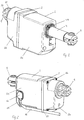
Fig. 1 , shows a perspective view of the actuator shown from the front, -
Fig. 2 , shows a perspective view of the actuator shown from the rear, -
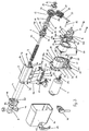
Fig. 3 , shows a exploded view of the actuator shown from the rear, -
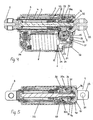
Fig. 4 , shows a longitudinal section through the actuator shown from the side, -
Fig. 5 , shows a longitudinal section through the actuator shown from above, -
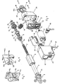
Fig. 6 , shows a exploded view of the actuator shown from the front, -
Fig. 7 , shows a perspective view of the mounting console shown from the rear from the opposite side, as shown inFig. 3 , and -
Fig. 8 , shows the circuit board shown from the opposite side and end as shown inFig. 3 . - The main components of the actuator shown on the drawing comprise a two-part
outer housing 1, a mountingconsole 2, anouter tube 3 secured to secured to the mountingconsole 2 with a rear end, and in which a telescopic tube shaped activation element 4 (in technical terminology an inner tube), aspindle 5 with aspindle nut 6 to which theactivation element 4 is mounted with a rear end, a reversible lowvoltage DC motor 7, a front mounting 8 secured to a free front end of theactivation element 4 and a rear mounting 9 at a rear end of theouter housing 1. - The two-part
outer housing 1 comprises a front part 1a and arear part 1b assembled around the mountingconsole 2, having across wall 2a with a circumferential flange 2b, and where the exterior of the flange corresponds to the outer contour of thehousing 1. Along the outer side of the circumferential flange 2b at each side a grove 2c for a sealing is arranged. In the corners are throughholes 10 forscrews 11. The twoparts 1a, 1b of thehousing 1 are assembled around the mountingconsole 2 in each corner with thescrews 11 at each corner which are inserted through theholes 10 in each corner of the mountingconsole 2. The screws are inserted from therear part 1b and are screwed into the front part 1a of the housing. - At one side of the
cross wall 2a of the mounting console there is a recess 12 (Fig. 4 ) for receiving the front part of themotor 7. The motor shaft 13 of the motor extends through a correspondinghole 14 in the mountingconsole 2. Themotor 7 is mounted to the mountingconsole 2 withscrews 15. - On the opposite side of the mounting
console 2 ahousing 16 with a first and a second end wall is mounted, where the one end wall is constituted by thecross wall 2a of the mounting console while the other end wall, thefree end wall 17, is an independent wall at a distance from thecross wail 2a. Between the twoend walls side wall 18, comprising a halfcircular wall element 18a which at its one end is extended into a short rectilinear wall element 18b and at the other end is extended into another longer rectilinear wall element 18c. In connection with the halfcircular wall element 18a in the free end wall is
arranged acircular opening 19 which is connected to acircular opening 20 in thecross wall 2a of the mounting console. Likewise, thehousing 16 has anopening 21 in the side wall between the two rectilinear wall elements 18b,18c. - A
transmission 22 mounted in thehousing 16 comprises a first worm gear theworm 23 of which is secured to the motor shaft 13. The free end of the worm is embedded in ahole 24 functioning as a slide bearing in thefree end wall 17 of the housing. Crosswise of the worm 23 a gear unit with a through goingaxle 25 is arranged. Saidaxle 25 is embedded with its ends in the two rectilinear wall elements 18b,18c and inclined in thehousing 16. In one end, the gear unit is equipped with atworm wheel 26 brought into mesh with theworm 23 at the motor shaft 13. The remaining part of the gear unit is constructed as asecond worm 27 with a large thread. The gear unit is led into thehousing 16 through theopening 21 in theside wall 18 of the housing. - A
shaft end 5a of the spindle is shaped as a D-spline upon which abushing 28 is arranged. On thebushing 28 is arranged aworm wheel 30 with a large thread brought into mesh with theworm 27 with the large thread on the gear unit by means of aspline connection 29. Thus, thespindle 5 is driven by themotor 7 over a transmission with twoworm gears worms 27 are moulded as a plastic component in one piece. Furthermore, theworm wheel 30 on thespindle 5 is also made of plastic. In that way a large gearing in the transmission is achieved, likewise, it is self-locking and thus prevents or locks thespindle 5 against rotation when the load on theactivation rod 4 attempts to rotate thespindle 5. - On the outer end of the
spindle 5 up against the worm wheel 30 aball bearing 31 is located, which with one side is extended over a stepped down downend 28a of thebushing 28. On the other side, the free side of thebearing 31, adisc 32 with a D-shaped opening which extends over the end of the spindle is located. Thedisc 32 is equipped with a hub protruding into the opening of the ball bearing and stabilises it. The outer end of thespindle 5 is shaped as a rivet head for retaining thedisc 32 and thebushing 28 on the D-shapedshaft end 5a of thespindle 5. - The rear mounting 9 is furnished with a
circular part 9a the outer end of which, the free end, is here equipped with a fork fitting 33 having a through through hole for a bolt or a shaft piece, but it might as well have been a flange with a through hole. On the opposite side, the inner side of the rear rear mounting 9, protruding into the housing 1 a recess 35 which is shaped as a seat for the ball bearing is located. This recess 35 is connected to an anopening 36 functioning as a seat for a cylindrical collar on the rear side side of the worm wheel 30 (Fig. 6 ). The recess 35 for theball bearing 31 31 and theopening 36 for the cylindrical collar 30a on theworm wheel 30 is connected to an opening 37 on the side of the rear mounting 9 such that it can be extended sidewards over theball bearing 31 and the collar 30a on theworm wheel 30. The opening 37 may be closed by means of an arc-shapedclosing element 38 which with atongue 38a at each side fits into aspline 37a at the side of the opening 37. The closingelement 38 is designed as a section in thecircular part 9a of the rear mounting 9. Thecircular part 9a of the rear mounting fits into thecircular opening 19 of thefree end wall 17 of thehousing 16 of the mountingconsole 2 and abuts the rim of thecircular opening 19 with the edge of a circular collar 9b which moreover functions as a stop for how far thecircular part 9a of the rear mounting 9 extends into thehousing 16. As thespindle 5 with theball bearing 31 is embedded in the rear mounting 9 the position of the spindle in proportion to the mountingconsole 2 is thus precisely determined. - At the back end of the
rear part 1b of the housing 1 acircular hole 39 is located through which the rear mounting 9 with the fork fitting 33 extends. Internally in the housing on the rim along theopening 39, a row ofteeth 40 is arranged more precisely forty-eight teeth. At the rear mounting 9 in connection with the circular collar 9b is arranged a stepping with two steps, of which the first step 9c is extended through theopening 39 of the housing while at the other step 9d two mutually facingsections teeth 40 at theopening 39 of the housing. One of the sections withteeth 41a is arranged at theclosing element 38. The arrangement of teeth allows the rear mounting and thus the fork fitting 33 can be rotated into a random angle position with intervals of 7.5°. - The
outer tube 3 is composed of a an aluminium tube with an almost square cross section as two diametrically located edges 3a are shaped as a as a soft circular arc while the twoother edges 3b are sharper i.e. with a a smaller radius of curvature. In each of these twocorners 3b ascrew channel 42 is arranged. The inner end, the end of thetube 3 protruding farthest into the housing, is riding at the edge of a tube shapedsocket 43 43 on the mountingconsole 2. Basically, the tube shapedsocket 43 is shaped in accordance with the shape of theouter tube 3. Theouter tube 3tube 3 is fastened to the mountingconsole 2 by means of screws which are are screwed into thescrew channels 42 of theouter tube 3 from the opposite side of the mountingconsole 2. In order to be able to guide the outer tube during the mounting process, the outer side of the tube shaped shapedsocket 43 is equipped with a number ofguide pins 43a. The outerouter tube 3 extends with its outer end through anopening 44 in the front of the front part of the housing. In order to prevent penetration of water between the outer tube and the housing a sealing is arranged in the opening. - The
activation element 4 comprises a tube section the inner end of which, i.e. the end located inside the housing comprises an inner threaded part by means of which it is screwed onto thespindle nut 6 the outer side of which for the purpose is equipped with a thread 6a. The front mounting 8 is secured to an outer end of theactivation element 4, i.e. the end of the tube section which is extended out of the front part of thehousing 1. The front mounting 8 is here equipped with a fork fitting 45 with a through hole comprising twobushings 46 for a mounting bolt or a shaft, it might as well be constructed as a butt strap with a through hole just like the rear mounting. The other end of the front mounting 8 is constructed as a threadedpart 8a by which it is screwed onto thetube section 4 which for the purpose is equipped with an inner thread. The position of the fork fitting can be adjusted stepless by simply turning thetube section 4 in its thread on the spindle nut. The thread coupling between the front mounting 8 and thetube section 4 is sealed so that water cannot penetrate into the actuator this way. - For guidance of the inner end of the tube shaped
activation element 4 in theouter tube 3, thespindle nut 6 is partly furnished with aneck 47, partly with guide surfaces 47a which are guiding against the inner side of theouter tube 3, and partly with guide bosses 47b which are guiding in axially running guides 3a, constructed for the purpose, inside the outer tube. Moreover, the guide bosses 47b function together with the guide surfaces 47a as rotation protection for thespindle nut 6 so this is secured against rotation and thus will be moved in and out on thespindle 5 dependent of the direction of rotation of the spindle. To prevent thespindle nut 6 from moving off thespindle 5, i.e. over the front of the spindle a mechanical stop shaped as a securedcircular disc 48 is mounted on the front of the spindle. At the front of theouter tube 3 anend plug 49 is fastened with screws which are screwed into thescrew channels 42 in theouter tube 3. Theend plug 49, which moreover is sealed against the end of theouter tube 3, has acentral opening 50 for the tube shapedactivation element 4 which is functioning as a guide for it. Theactivation element 4 is thus guided in theouter tube 3 both at its rear end and at the front of the outer tube. The opening of theend plug 49 is equipped with seals in the form of o-rings for theactivation element 4 to prevent water to penetrate into the actuator. One of the soft curved corners 3a of theouter tube 3 has two guides 51 for a strip shapedactivation rod 52 which has an opening 52a at the rear part and a dog 52b in the form of an embossing at the front part. When theactivation element 4 is brought into its outermost position, a guide boss 47b on thespindle nut 6 will hit the dog 52b and pull theactivation rod 52 along until the motor stops. - At the front of the mounting
console 2 edgeways at the side of theouter tube 3, acircuit board 53 with switches is arranged. The end of the circuit circuit board rests against the tube shapedsocket 43 on the mountingconsole 2, and the front edge is fixed between its side and pins on the mountingconsole 2. Thecircuit board 53 has ahole 53a for insertion over apin 43b at the side of the tube shapedsocket 43 such that thecircuit board 53 is secured in the axial direction as well as in the sideways direction. On thecircuit board 53 two end stop switches 54, 55 are arranged below a longitudinaldisplaceable housing 56 which with a leg 56a at each end reaches into the guide 53b in thecircuit board 53. Thehousing 56 is springloaded by acoil spring 57 to occupy a neutral position in which none of the end stop switches 54,55 are activated. Thecoil spring 57 is arranged in a groove in the circuit board. Each end of the groove is connected to a guide through which two tabs 56b are arranged on the housing between which thecoil spring 57 is embedded. On one side of thehousing 56 is anarm 58 which is extended into the hollow of the tube shapedsocket 43 through an opening. The aforementioned strip shapedactivation rod 52 in theouter tube 3 is attached to thearm 58 with the opening 52a. When theactivation element 4 reaches its outermost end position the displacement of theactivation rod 52 will pull thehousing 56 along and activate the corresponding end stop switch 55. This happens in that the ceiling 56a of the housing is countersunk at the ends such that the contact on the end stop switch 55 is pressed down when it passes over the end stop switch 55. By activating the end stop switch 55 the motor will be stopped by switching off the power for it by means of guide electronics (not shown). At the inner retracted end position of the activation element 4 a guide boss 47a on thespindle nut 6 hits thearm 58 and thus pulls thehousing 56 along and activates the other end stopswitch 54. Again the power for the motor is switched off by the guide electronics. On the other side of thecircuit board 53 two position switches 57a, 57b are arranged which will be activated by the tab 56b on thehousing 56. These position switches signal to the control unit about which end position theactivation element 4 is in. Note that the positions switches 57a, 57b are expendable if it is not necessary to know which end position theactivation element 4 are in. Also note that the end stop switches 54, 55 can function as power switches which cut off the current to themotor 7 in order to simplify the guide electronics. However, it is often a strong wish that the mains voltage is kept as far from the actuator as possible for safety reasons. - Further, it is noted that if necessary the
spindle nut 6 may be equipped with ametal safety nut 59, applied in a groove at the end of thespindle nut 6 which typically is made of plastic in order to dampen noise. When the actuator is only exposed to pressure load only onesafety nut 59 at the rear end of thespindle nut 6 is required, and when the actuator is only exposed to tensile load, only a safety nut at the front of the spindle nut is required. When the actuator is exposed to both pressure load and tensile load a safety nut can be arranged at each end. - The determination of the position of the
activation element 4 may, as mentioned above, be done in different ways, e.g. with a Hall-element arranged on the printedcircuit board 53. At a collar 30b at the front of theworm wheel 30 on thespindle 5 amagnet ring 60 with more poles is embedded, which triggers the Hall-element each time a pole passes it. Themagnet ring 60 is retained in its position by a lockingring 61. - For the sake of completeness it is noted that 62 is a plug from the control device which is connected to the socket of the
circuit board 64 through agateway 63 in the outer housing. Thegateway 63 is arranged in a countersunk area on the housing. To prevent theplug 62 from unintentionally being pulled out it can be locked by a lockingelement 65 which constitutes part of the front part 1a of the housing. At a lower edge of thehousing 1, a groove shaped notch for acable 66 for theplug 62. Thecable 66 is secured by aclamp 67 arranged in the corner of the mounting console. The cable thus lies within the circumscribed rectangle of the housing and is thus properly protected. - The invention thus provides a linear actuator which provides the possibility of low manufacturing costs while the actuator still maintains a high quality and strength as well as a high degree of flexibility in terms of accessories and mounting brackets (front and rear mounting).
Claims (10)
- Linear actuator comprising a housing (1) consisting of at least two parts (1a, 1b) a mounting console (2) a reversible motor (7) with a transmission (22), a spindle (5) which over the transmission is driven by the reversible motor (7), a bearing (31) for embedding the spindle (5), a spindle nut (6) secured against rotation on the spindle (5), an outer tube (3) which surrounds the spindle (5), an activation element (4) telescopic mounted in the outer tube (3) and connected to the spindle nut (6), a front mounting (8) on the outer end of the activation element (4), a rear mounting (9) arranged in the housing (1) and where there in the rear mounting (9) is a seat (35) for the bearing (31) of the spindle (5), and where the reversible motor (7), the transmission (22) and the outer tube (3) is secured to the mounting console (2), and where the mounting console (2) is designed as a separate element which constitutes the bearing chassis of the linear actuator,
characterized in that the mounting console (2) is equipped with a wall element (2a) around and on which the two parts (1a, 1b) of the housing (1), the reversible motor (7), the transmission (22) and the outer tube (3) of the linear actuator is mounted, and where the outer contour of the wall element (2a) of the mounting console (2) corresponds to or essentially corresponds to the outer contour of the cross section of the housing (1). - Actuator according to claim 1, characterized in that the motor (7) is arranged parallel to the spindle (5).
- Actuator according to claim 1, characterized in that the motor (7) is located along a shaft end (5a) of the spindle (5).
- Actuator according to claim 1, characterized in that the housing consists of two parts (1a, 1b) with an assembly plane perpendicular to the length axis of the spindle (5).
- Actuator according to claim 1, characterized in that the mounting console (2) is furnished with a compartment (1b) containing the transmission (22).
- Actuator according to claim 1, characterized in that the mounting console (2) is equipped with a tube shaped socket (43), the inner and outer contour of which corresponds to or in all essentials corresponds to the inner and outer contour of the outer tube (3), so that said outer tube (3) stands on a free edge of the tube shaped socket (43).
- Actuator according to claim 6, characterized in that the outer tube (3) is secured to the mounting console (2) with screws, as screw channels (42) for that purpose are constructed in the outer tube (3).
- Actuator according to claim 1, characterized in that it comprises a printed circuit board (53) with end stop switches (54,55) mounted on the side of the tube shaped socket (43) and that a slider with an arm (58) for activating the end stop switches is located on the printed circuit board (53), where the spindle nut (6) in an innermost end position operates the arm (58) on the slider and that an axially displaceable rod (52) is embedded in the outer tube (3), which with one end is secured to the arm (58) while the other end is equipped with a dog (52b), which is operated by the spindle nut (6) in its other end position.
- Actuator according to claim 1, characterized in that the rear mounting (9) is equipped with a seat (35) for the bearing (31) of the spindle, and that the seat (35) is connected to an opening (37) leading out to the side of the rear mounting (9) so that the bearing (31) of the spindle may be inserted sideways into the seat (35).
- Actuator according to claim 1 or 9, characterized in that the rear mounting (9) is constructed as a separate element and retained between the housing on the mounting console (2) and an end wall at the rear end of the housing.
Priority Applications (1)
| Application Number | Priority Date | Filing Date | Title |
|---|---|---|---|
| PL10800687T PL2499398T3 (en) | 2009-11-13 | 2010-11-11 | Linear actuator |
Applications Claiming Priority (2)
| Application Number | Priority Date | Filing Date | Title |
|---|---|---|---|
| DKPA200901215 | 2009-11-13 | ||
| PCT/DK2010/000148 WO2011057632A1 (en) | 2009-11-13 | 2010-11-11 | Linear actuator |
Publications (2)
| Publication Number | Publication Date |
|---|---|
| EP2499398A1 EP2499398A1 (en) | 2012-09-19 |
| EP2499398B1 true EP2499398B1 (en) | 2018-10-10 |
Family
ID=43480964
Family Applications (1)
| Application Number | Title | Priority Date | Filing Date |
|---|---|---|---|
| EP10800687.5A Active EP2499398B1 (en) | 2009-11-13 | 2010-11-11 | Linear actuator |
Country Status (13)
| Country | Link |
|---|---|
| US (1) | US8939043B2 (en) |
| EP (1) | EP2499398B1 (en) |
| JP (1) | JP5638620B2 (en) |
| CN (1) | CN102667247B (en) |
| AU (1) | AU2010318398A1 (en) |
| BR (1) | BR112012009038A2 (en) |
| DK (1) | DK2499398T3 (en) |
| HU (1) | HUE041550T2 (en) |
| IN (1) | IN2012DN02999A (en) |
| PL (1) | PL2499398T3 (en) |
| RU (1) | RU2549422C2 (en) |
| TR (1) | TR201819461T4 (en) |
| WO (1) | WO2011057632A1 (en) |
Families Citing this family (28)
| Publication number | Priority date | Publication date | Assignee | Title |
|---|---|---|---|---|
| US8448540B2 (en) * | 2009-12-07 | 2013-05-28 | Hiwin Mikrosystem Corp. | Assembling mechanism of a self-locking linear actuator |
| DE202010009334U1 (en) * | 2010-06-21 | 2011-09-22 | BROSE SCHLIEßSYSTEME GMBH & CO. KG | Spindle drive for the motorized adjustment of an adjusting element of a motor vehicle |
| RU2561023C2 (en) * | 2010-08-31 | 2015-08-20 | Киекерт Акциенгезельшафт | Actuator for automotive industry |
| DK2619889T3 (en) * | 2010-09-24 | 2019-07-22 | Thomson Ind Inc | Linear actuator |
| US8794087B2 (en) * | 2012-06-08 | 2014-08-05 | Timotion Technology Co., Ltd. | Gear motor having safety mechanism |
| US9182022B2 (en) * | 2012-10-17 | 2015-11-10 | Honeywell International Inc. | Ball screw actuator including a stop with an integral guide |
| CN103322149B (en) * | 2013-01-14 | 2015-09-23 | 深圳矽递科技有限公司 | spiral linear telescopic structure |
| JP6243399B2 (en) * | 2013-02-28 | 2017-12-06 | 日本電産サンキョー株式会社 | Motor equipment |
| CN103683639B (en) * | 2013-12-27 | 2015-12-09 | 中山大洋电机制造有限公司 | A kind of DC and AC universal electric machine |
| FR3019523B1 (en) * | 2014-04-08 | 2018-02-02 | Safran Landing Systems | METHOD FOR OPERATING AIRCRAFT SAIL TRAPPERS, AND ACTUATOR APPLYING THE SAME |
| KR101532775B1 (en) * | 2014-06-20 | 2015-07-02 | 현대다이모스(주) | Apparatus for moving on electric seat rail |
| EP3453918A1 (en) | 2014-07-29 | 2019-03-13 | Linak A/S | Linear actuator |
| US10746269B2 (en) * | 2014-10-31 | 2020-08-18 | D-Box Technologies Inc. | Linear actuator for motion simulator |
| DE102015204074B4 (en) * | 2015-03-06 | 2016-12-15 | Schaeffler Technologies AG & Co. KG | Linear actuator and method for mounting an actuator |
| RU2617007C1 (en) * | 2015-10-23 | 2017-04-19 | Валентин Алексеевич Абрамов | Method of manufacturing and assembly/disassembly of wave transmission and device for their implementation in it sealed and nongermetic execution of abramov v.a. |
| DE202015105851U1 (en) | 2015-11-03 | 2015-11-10 | Innotec Motion GmbH | Seating Chassis |
| DE202015105865U1 (en) * | 2015-11-04 | 2015-11-11 | Innotec Motion GmbH | Seating Chassis |
| DE202016101749U1 (en) * | 2015-11-04 | 2017-02-07 | Elektrosil Systeme Der Elektronik Gmbh | Adjustment device for adjusting a headrest position with direct drive |
| CN105565200B (en) * | 2016-02-25 | 2017-12-19 | 常州市凯迪电器股份有限公司 | Three-section type Linear actuator and its drive component |
| US10008838B1 (en) * | 2017-04-13 | 2018-06-26 | Robert C. Rhodes | Cable pulling device |
| CN107314090A (en) * | 2017-07-04 | 2017-11-03 | 浙江捷昌线性驱动科技股份有限公司 | It is a kind of can bidirectional self-locking electric pushrod |
| DE102017212823A1 (en) * | 2017-07-26 | 2019-01-31 | Stabilus Gmbh | Spindle drive means |
| WO2019137587A1 (en) * | 2018-01-12 | 2019-07-18 | Linak A/S | Linear actuator |
| RU2700562C1 (en) * | 2018-12-10 | 2019-09-20 | Владимир Ростиславович Борецкий | Linear actuator and linear actuating mechanism |
| EP3719352A1 (en) * | 2019-04-05 | 2020-10-07 | Flender GmbH | Transmission housing, sensor installation kit and transmission |
| DE102019205972A1 (en) * | 2019-04-25 | 2020-10-29 | Robert Bosch Gmbh | Electromechanical brake pressure generator for a hydraulic brake system of a vehicle and vehicle comprising an electromechanical brake pressure generator |
| DE102020118449A1 (en) * | 2020-07-13 | 2022-01-13 | Ewellix AB | Linear Actuator, Housing, Actuation System, and Assembly Method |
| EP3989414A1 (en) * | 2020-10-22 | 2022-04-27 | Cyltronic AG | Electric cylinder, electric cylinder with a magnet for determining the position of a rotating element of an electric cylinder and use of a magnet for determining the position of a rotating element |
Family Cites Families (34)
| Publication number | Priority date | Publication date | Assignee | Title |
|---|---|---|---|---|
| US3132532A (en) * | 1960-08-09 | 1964-05-12 | Amsted Ind Inc | Slack adjuster assembly |
| US4583421A (en) * | 1985-01-11 | 1986-04-22 | Rose Marvin D | Powered adjuster for three-point hitch upper arm |
| US4858481A (en) * | 1985-05-13 | 1989-08-22 | Brunswick Valve & Control, Inc. | Position controlled linear actuator |
| IT210468Z2 (en) * | 1987-01-21 | 1988-12-30 | Iveco Fiat | ELECTROMECHANICAL LINEAR ACTUATOR FOR TILTING THE DRIVER'S CABIN OF AN INDUSTRIAL VEHICLE |
| GB2250189B (en) | 1990-11-28 | 1993-11-24 | Nesbit Evans & Co Ltd | Beds |
| DK155291A (en) | 1991-09-04 | 1993-03-05 | Linak As | ACTUATOR |
| DK171217B1 (en) | 1992-09-01 | 1996-07-29 | Linak As | Linear actuator |
| DK171618B1 (en) | 1993-10-12 | 1997-02-24 | Linak As | Linear actuator |
| DK4094A (en) | 1994-01-10 | 1995-07-11 | Linak As | Linear actuator |
| DE9404383U1 (en) | 1994-03-17 | 1994-05-05 | Dewert Antriebs Systemtech | Electromotive adjustment drive |
| GB9415648D0 (en) * | 1994-08-03 | 1994-09-21 | Rotork Controls | Differential drive linear actuator |
| US5892309A (en) | 1997-01-17 | 1999-04-06 | Von Weise Gear Company | Electro-mechanical linear actuator |
| JPH09224348A (en) * | 1996-02-16 | 1997-08-26 | Nippon Seiko Kk | Motor type linear actuator |
| US5809833A (en) | 1996-09-24 | 1998-09-22 | Dana Corporation | Linear actuator |
| DK151096A (en) | 1996-12-23 | 1998-07-17 | Linak As | Linear actuator |
| ES2190056T3 (en) * | 1998-01-20 | 2003-07-16 | Skf Eng & Res Centre Bv | MODULAR PERFECTED DEVICE AND BRAKE SHOE UNDERSTANDING SUCH ACTUATOR. |
| US6259175B1 (en) * | 1999-11-18 | 2001-07-10 | Dana Corporation | Linear actuator |
| JP4034650B2 (en) * | 2000-10-03 | 2008-01-16 | リナック エー/エス | Linear actuator |
| ITTO20011163A1 (en) * | 2001-12-13 | 2003-06-13 | Skf Ind Spa | SCREW ACTUATOR WITH FIXED MOTOR SCREW. |
| DE202004000950U1 (en) * | 2004-01-22 | 2004-04-01 | Jaeger Industrial Co., Ltd., Sindian | Linear servo component for lifting devices like hospital beds includes a guide screw with a threaded section and a worm wheel to engage a motor shaft |
| RU2297563C2 (en) * | 2004-11-24 | 2007-04-20 | Вячеслав Васильевич Козырев | Electric drive on the base of a gear with long thread rolls |
| CN1854562A (en) * | 2005-04-26 | 2006-11-01 | 大银微系统股份有限公司 | Linear actuator with fast releaser |
| TWM296325U (en) * | 2005-12-27 | 2006-08-21 | Jaeger Ind Co Ltd | Linear transmission device with quick-release function |
| US7779973B2 (en) * | 2006-07-05 | 2010-08-24 | Chen-Hui Ko | Transmission mechanism with the function of the shock absorption |
| DE202006018505U1 (en) | 2006-12-05 | 2008-04-17 | Dewert Antriebs- Und Systemtechnik Gmbh | Electromotive linear drive |
| WO2008080400A2 (en) * | 2006-12-31 | 2008-07-10 | Linak A/S | Actuator system |
| US7533591B2 (en) * | 2007-03-03 | 2009-05-19 | T-Motion Technology Co., Ltd. | Fast-releasing controlling device of actuator for electric sickbed |
| JP5218817B2 (en) * | 2007-05-17 | 2013-06-26 | 日本精工株式会社 | Actuator |
| TWI383276B (en) * | 2007-12-04 | 2013-01-21 | Smc Kk | Electric actuator |
| JP5524078B2 (en) * | 2008-01-12 | 2014-06-18 | リナック エー/エス | Linear actuator |
| DE102008021861A1 (en) * | 2008-05-02 | 2009-11-05 | Schaeffler Kg | Fahrwerksaktuator |
| US8358096B2 (en) * | 2008-06-27 | 2013-01-22 | Linak A/S | Linear actuator |
| TWM356733U (en) * | 2008-12-05 | 2009-05-11 | Moteck Electric Corp | Push rod structure |
| US8448540B2 (en) * | 2009-12-07 | 2013-05-28 | Hiwin Mikrosystem Corp. | Assembling mechanism of a self-locking linear actuator |
-
2010
- 2010-11-11 RU RU2012123465/11A patent/RU2549422C2/en not_active IP Right Cessation
- 2010-11-11 IN IN2999DEN2012 patent/IN2012DN02999A/en unknown
- 2010-11-11 TR TR2018/19461T patent/TR201819461T4/en unknown
- 2010-11-11 PL PL10800687T patent/PL2499398T3/en unknown
- 2010-11-11 BR BR112012009038A patent/BR112012009038A2/en not_active IP Right Cessation
- 2010-11-11 DK DK10800687.5T patent/DK2499398T3/en active
- 2010-11-11 EP EP10800687.5A patent/EP2499398B1/en active Active
- 2010-11-11 WO PCT/DK2010/000148 patent/WO2011057632A1/en active Application Filing
- 2010-11-11 US US13/509,318 patent/US8939043B2/en not_active Expired - Fee Related
- 2010-11-11 JP JP2012538194A patent/JP5638620B2/en not_active Expired - Fee Related
- 2010-11-11 AU AU2010318398A patent/AU2010318398A1/en not_active Abandoned
- 2010-11-11 CN CN201080048172.6A patent/CN102667247B/en not_active Expired - Fee Related
- 2010-11-11 HU HUE10800687A patent/HUE041550T2/en unknown
Non-Patent Citations (1)
| Title |
|---|
| None * |
Also Published As
| Publication number | Publication date |
|---|---|
| CN102667247A (en) | 2012-09-12 |
| JP5638620B2 (en) | 2014-12-10 |
| HUE041550T2 (en) | 2019-05-28 |
| CN102667247B (en) | 2016-03-23 |
| JP2013510998A (en) | 2013-03-28 |
| BR112012009038A2 (en) | 2016-04-19 |
| RU2549422C2 (en) | 2015-04-27 |
| EP2499398A1 (en) | 2012-09-19 |
| AU2010318398A1 (en) | 2012-05-03 |
| RU2012123465A (en) | 2013-12-20 |
| US20120222510A1 (en) | 2012-09-06 |
| IN2012DN02999A (en) | 2015-07-31 |
| US8939043B2 (en) | 2015-01-27 |
| PL2499398T3 (en) | 2019-04-30 |
| TR201819461T4 (en) | 2019-01-21 |
| WO2011057632A1 (en) | 2011-05-19 |
| DK2499398T3 (en) | 2019-01-14 |
Similar Documents
| Publication | Publication Date | Title |
|---|---|---|
| EP2499398B1 (en) | Linear actuator | |
| DK2970921T3 (en) | Histidyl-tRNA synthetase-Fc conjugates | |
| EP2499397B1 (en) | Linear actuator | |
| EP2232101B1 (en) | Linear actuator | |
| US8672284B2 (en) | Gear with at least two gearing stages, a linear actuator including such a gear and a table leg including such a linear actuator | |
| EP1718885B1 (en) | A linear actuator comprising an overload clutch | |
| US20080134815A1 (en) | Linear Actuator | |
| EP1322876A1 (en) | A linear actuator | |
| CN108438133A (en) | Rear derailleur | |
| AU2006215577A1 (en) | Electromotive linear drive | |
| US7935901B2 (en) | Actuator assembly and bed | |
| EP1902236B1 (en) | Actuator with means for determining the position of an activation element | |
| US8857283B2 (en) | Ball screw | |
| AU3917899A (en) | Electrically controlled clamping device for a system for adjusting the position of one member relative to another member | |
| KR20120062560A (en) | Parking release actuator | |
| US9453562B2 (en) | Valve actuator torque limiter | |
| EP0857639A2 (en) | Steering gear | |
| US11384820B2 (en) | Linear actuator | |
| KR100596114B1 (en) | Electron type parking brake |
Legal Events
| Date | Code | Title | Description |
|---|---|---|---|
| PUAI | Public reference made under article 153(3) epc to a published international application that has entered the european phase |
Free format text: ORIGINAL CODE: 0009012 |
|
| 17P | Request for examination filed |
Effective date: 20120612 |
|
| AK | Designated contracting states |
Kind code of ref document: A1 Designated state(s): AL AT BE BG CH CY CZ DE DK EE ES FI FR GB GR HR HU IE IS IT LI LT LU LV MC MK MT NL NO PL PT RO RS SE SI SK SM TR |
|
| DAX | Request for extension of the european patent (deleted) | ||
| GRAP | Despatch of communication of intention to grant a patent |
Free format text: ORIGINAL CODE: EPIDOSNIGR1 |
|
| STAA | Information on the status of an ep patent application or granted ep patent |
Free format text: STATUS: GRANT OF PATENT IS INTENDED |
|
| INTG | Intention to grant announced |
Effective date: 20180502 |
|
| RIN1 | Information on inventor provided before grant (corrected) |
Inventor name: WINTHER, HENRIK Inventor name: TORRES, JUAN, MIGUEL, GALINDO Inventor name: IVERSEN, TORBEN |
|
| GRAS | Grant fee paid |
Free format text: ORIGINAL CODE: EPIDOSNIGR3 |
|
| GRAA | (expected) grant |
Free format text: ORIGINAL CODE: 0009210 |
|
| STAA | Information on the status of an ep patent application or granted ep patent |
Free format text: STATUS: THE PATENT HAS BEEN GRANTED |
|
| AK | Designated contracting states |
Kind code of ref document: B1 Designated state(s): AL AT BE BG CH CY CZ DE DK EE ES FI FR GB GR HR HU IE IS IT LI LT LU LV MC MK MT NL NO PL PT RO RS SE SI SK SM TR |
|
| REG | Reference to a national code |
Ref country code: GB Ref legal event code: FG4D |
|
| REG | Reference to a national code |
Ref country code: CH Ref legal event code: EP Ref country code: AT Ref legal event code: REF Ref document number: 1051631 Country of ref document: AT Kind code of ref document: T Effective date: 20181015 |
|
| REG | Reference to a national code |
Ref country code: IE Ref legal event code: FG4D |
|
| REG | Reference to a national code |
Ref country code: DE Ref legal event code: R096 Ref document number: 602010054254 Country of ref document: DE |
|
| REG | Reference to a national code |
Ref country code: CH Ref legal event code: NV Representative=s name: TROESCH SCHEIDEGGER WERNER AG, CH |
|
| REG | Reference to a national code |
Ref country code: DK Ref legal event code: T3 Effective date: 20190106 |
|
| REG | Reference to a national code |
Ref country code: NL Ref legal event code: FP |
|
| REG | Reference to a national code |
Ref country code: SE Ref legal event code: TRGR |
|
| REG | Reference to a national code |
Ref country code: LT Ref legal event code: MG4D |
|
| REG | Reference to a national code |
Ref country code: AT Ref legal event code: MK05 Ref document number: 1051631 Country of ref document: AT Kind code of ref document: T Effective date: 20181010 |
|
| PG25 | Lapsed in a contracting state [announced via postgrant information from national office to epo] |
Ref country code: FI Free format text: LAPSE BECAUSE OF FAILURE TO SUBMIT A TRANSLATION OF THE DESCRIPTION OR TO PAY THE FEE WITHIN THE PRESCRIBED TIME-LIMIT Effective date: 20181010 Ref country code: LV Free format text: LAPSE BECAUSE OF FAILURE TO SUBMIT A TRANSLATION OF THE DESCRIPTION OR TO PAY THE FEE WITHIN THE PRESCRIBED TIME-LIMIT Effective date: 20181010 Ref country code: HR Free format text: LAPSE BECAUSE OF FAILURE TO SUBMIT A TRANSLATION OF THE DESCRIPTION OR TO PAY THE FEE WITHIN THE PRESCRIBED TIME-LIMIT Effective date: 20181010 Ref country code: AT Free format text: LAPSE BECAUSE OF FAILURE TO SUBMIT A TRANSLATION OF THE DESCRIPTION OR TO PAY THE FEE WITHIN THE PRESCRIBED TIME-LIMIT Effective date: 20181010 Ref country code: LT Free format text: LAPSE BECAUSE OF FAILURE TO SUBMIT A TRANSLATION OF THE DESCRIPTION OR TO PAY THE FEE WITHIN THE PRESCRIBED TIME-LIMIT Effective date: 20181010 Ref country code: BG Free format text: LAPSE BECAUSE OF FAILURE TO SUBMIT A TRANSLATION OF THE DESCRIPTION OR TO PAY THE FEE WITHIN THE PRESCRIBED TIME-LIMIT Effective date: 20190110 Ref country code: ES Free format text: LAPSE BECAUSE OF FAILURE TO SUBMIT A TRANSLATION OF THE DESCRIPTION OR TO PAY THE FEE WITHIN THE PRESCRIBED TIME-LIMIT Effective date: 20181010 Ref country code: NO Free format text: LAPSE BECAUSE OF FAILURE TO SUBMIT A TRANSLATION OF THE DESCRIPTION OR TO PAY THE FEE WITHIN THE PRESCRIBED TIME-LIMIT Effective date: 20190110 Ref country code: IS Free format text: LAPSE BECAUSE OF FAILURE TO SUBMIT A TRANSLATION OF THE DESCRIPTION OR TO PAY THE FEE WITHIN THE PRESCRIBED TIME-LIMIT Effective date: 20190210 |
|
| PGFP | Annual fee paid to national office [announced via postgrant information from national office to epo] |
Ref country code: CH Payment date: 20190123 Year of fee payment: 9 Ref country code: NL Payment date: 20181228 Year of fee payment: 9 Ref country code: PL Payment date: 20190114 Year of fee payment: 9 |
|
| REG | Reference to a national code |
Ref country code: HU Ref legal event code: AG4A Ref document number: E041550 Country of ref document: HU |
|
| PG25 | Lapsed in a contracting state [announced via postgrant information from national office to epo] |
Ref country code: AL Free format text: LAPSE BECAUSE OF FAILURE TO SUBMIT A TRANSLATION OF THE DESCRIPTION OR TO PAY THE FEE WITHIN THE PRESCRIBED TIME-LIMIT Effective date: 20181010 Ref country code: GR Free format text: LAPSE BECAUSE OF FAILURE TO SUBMIT A TRANSLATION OF THE DESCRIPTION OR TO PAY THE FEE WITHIN THE PRESCRIBED TIME-LIMIT Effective date: 20190111 Ref country code: PT Free format text: LAPSE BECAUSE OF FAILURE TO SUBMIT A TRANSLATION OF THE DESCRIPTION OR TO PAY THE FEE WITHIN THE PRESCRIBED TIME-LIMIT Effective date: 20190210 Ref country code: RS Free format text: LAPSE BECAUSE OF FAILURE TO SUBMIT A TRANSLATION OF THE DESCRIPTION OR TO PAY THE FEE WITHIN THE PRESCRIBED TIME-LIMIT Effective date: 20181010 |
|
| PGFP | Annual fee paid to national office [announced via postgrant information from national office to epo] |
Ref country code: BE Payment date: 20181228 Year of fee payment: 9 |
|
| REG | Reference to a national code |
Ref country code: DE Ref legal event code: R097 Ref document number: 602010054254 Country of ref document: DE |
|
| PG25 | Lapsed in a contracting state [announced via postgrant information from national office to epo] |
Ref country code: CZ Free format text: LAPSE BECAUSE OF FAILURE TO SUBMIT A TRANSLATION OF THE DESCRIPTION OR TO PAY THE FEE WITHIN THE PRESCRIBED TIME-LIMIT Effective date: 20181010 Ref country code: LU Free format text: LAPSE BECAUSE OF NON-PAYMENT OF DUE FEES Effective date: 20181111 |
|
| PLBE | No opposition filed within time limit |
Free format text: ORIGINAL CODE: 0009261 |
|
| STAA | Information on the status of an ep patent application or granted ep patent |
Free format text: STATUS: NO OPPOSITION FILED WITHIN TIME LIMIT |
|
| REG | Reference to a national code |
Ref country code: IE Ref legal event code: MM4A |
|
| PG25 | Lapsed in a contracting state [announced via postgrant information from national office to epo] |
Ref country code: EE Free format text: LAPSE BECAUSE OF FAILURE TO SUBMIT A TRANSLATION OF THE DESCRIPTION OR TO PAY THE FEE WITHIN THE PRESCRIBED TIME-LIMIT Effective date: 20181010 Ref country code: SM Free format text: LAPSE BECAUSE OF FAILURE TO SUBMIT A TRANSLATION OF THE DESCRIPTION OR TO PAY THE FEE WITHIN THE PRESCRIBED TIME-LIMIT Effective date: 20181010 Ref country code: SK Free format text: LAPSE BECAUSE OF FAILURE TO SUBMIT A TRANSLATION OF THE DESCRIPTION OR TO PAY THE FEE WITHIN THE PRESCRIBED TIME-LIMIT Effective date: 20181010 Ref country code: MC Free format text: LAPSE BECAUSE OF FAILURE TO SUBMIT A TRANSLATION OF THE DESCRIPTION OR TO PAY THE FEE WITHIN THE PRESCRIBED TIME-LIMIT Effective date: 20181010 Ref country code: RO Free format text: LAPSE BECAUSE OF FAILURE TO SUBMIT A TRANSLATION OF THE DESCRIPTION OR TO PAY THE FEE WITHIN THE PRESCRIBED TIME-LIMIT Effective date: 20181010 |
|
| 26N | No opposition filed |
Effective date: 20190711 |
|
| PG25 | Lapsed in a contracting state [announced via postgrant information from national office to epo] |
Ref country code: IE Free format text: LAPSE BECAUSE OF NON-PAYMENT OF DUE FEES Effective date: 20181111 Ref country code: SI Free format text: LAPSE BECAUSE OF FAILURE TO SUBMIT A TRANSLATION OF THE DESCRIPTION OR TO PAY THE FEE WITHIN THE PRESCRIBED TIME-LIMIT Effective date: 20181010 |
|
| PG25 | Lapsed in a contracting state [announced via postgrant information from national office to epo] |
Ref country code: MT Free format text: LAPSE BECAUSE OF NON-PAYMENT OF DUE FEES Effective date: 20181111 |
|
| PG25 | Lapsed in a contracting state [announced via postgrant information from national office to epo] |
Ref country code: MK Free format text: LAPSE BECAUSE OF NON-PAYMENT OF DUE FEES Effective date: 20181010 Ref country code: CY Free format text: LAPSE BECAUSE OF FAILURE TO SUBMIT A TRANSLATION OF THE DESCRIPTION OR TO PAY THE FEE WITHIN THE PRESCRIBED TIME-LIMIT Effective date: 20181010 |
|
| REG | Reference to a national code |
Ref country code: CH Ref legal event code: PL |
|
| REG | Reference to a national code |
Ref country code: NL Ref legal event code: MM Effective date: 20191201 |
|
| PG25 | Lapsed in a contracting state [announced via postgrant information from national office to epo] |
Ref country code: LI Free format text: LAPSE BECAUSE OF NON-PAYMENT OF DUE FEES Effective date: 20191130 Ref country code: CH Free format text: LAPSE BECAUSE OF NON-PAYMENT OF DUE FEES Effective date: 20191130 |
|
| REG | Reference to a national code |
Ref country code: BE Ref legal event code: MM Effective date: 20191130 |
|
| PG25 | Lapsed in a contracting state [announced via postgrant information from national office to epo] |
Ref country code: HU Free format text: LAPSE BECAUSE OF NON-PAYMENT OF DUE FEES Effective date: 20191112 |
|
| PG25 | Lapsed in a contracting state [announced via postgrant information from national office to epo] |
Ref country code: NL Free format text: LAPSE BECAUSE OF NON-PAYMENT OF DUE FEES Effective date: 20191201 |
|
| PG25 | Lapsed in a contracting state [announced via postgrant information from national office to epo] |
Ref country code: BE Free format text: LAPSE BECAUSE OF NON-PAYMENT OF DUE FEES Effective date: 20191130 |
|
| PGFP | Annual fee paid to national office [announced via postgrant information from national office to epo] |
Ref country code: TR Payment date: 20201109 Year of fee payment: 11 |
|
| PGFP | Annual fee paid to national office [announced via postgrant information from national office to epo] |
Ref country code: SE Payment date: 20201125 Year of fee payment: 11 Ref country code: GB Payment date: 20201119 Year of fee payment: 11 |
|
| PG25 | Lapsed in a contracting state [announced via postgrant information from national office to epo] |
Ref country code: PL Free format text: LAPSE BECAUSE OF NON-PAYMENT OF DUE FEES Effective date: 20191111 |
|
| GBPC | Gb: european patent ceased through non-payment of renewal fee |
Effective date: 20211111 |
|
| PG25 | Lapsed in a contracting state [announced via postgrant information from national office to epo] |
Ref country code: SE Free format text: LAPSE BECAUSE OF NON-PAYMENT OF DUE FEES Effective date: 20211112 |
|
| PG25 | Lapsed in a contracting state [announced via postgrant information from national office to epo] |
Ref country code: GB Free format text: LAPSE BECAUSE OF NON-PAYMENT OF DUE FEES Effective date: 20211111 |
|
| P01 | Opt-out of the competence of the unified patent court (upc) registered |
Effective date: 20230525 |
|
| PGFP | Annual fee paid to national office [announced via postgrant information from national office to epo] |
Ref country code: IT Payment date: 20231121 Year of fee payment: 14 Ref country code: FR Payment date: 20231120 Year of fee payment: 14 Ref country code: DK Payment date: 20231124 Year of fee payment: 14 Ref country code: DE Payment date: 20231121 Year of fee payment: 14 |