EP2619829B1 - Unité d'accumulation d'energie rechargeable - Google Patents
Unité d'accumulation d'energie rechargeable Download PDFInfo
- Publication number
- EP2619829B1 EP2619829B1 EP11761322.4A EP11761322A EP2619829B1 EP 2619829 B1 EP2619829 B1 EP 2619829B1 EP 11761322 A EP11761322 A EP 11761322A EP 2619829 B1 EP2619829 B1 EP 2619829B1
- Authority
- EP
- European Patent Office
- Prior art keywords
- energy storage
- storage unit
- particles
- rechargeable energy
- electrode
- Prior art date
- Legal status (The legal status is an assumption and is not a legal conclusion. Google has not performed a legal analysis and makes no representation as to the accuracy of the status listed.)
- Not-in-force
Links
- 238000004146 energy storage Methods 0.000 title claims description 75
- 239000002245 particle Substances 0.000 claims description 64
- 239000013528 metallic particle Substances 0.000 claims description 40
- 229910044991 metal oxide Inorganic materials 0.000 claims description 30
- 150000004706 metal oxides Chemical class 0.000 claims description 30
- 239000001301 oxygen Substances 0.000 claims description 27
- 229910052760 oxygen Inorganic materials 0.000 claims description 27
- -1 oxygen ions Chemical class 0.000 claims description 18
- 239000000463 material Substances 0.000 claims description 17
- 238000005245 sintering Methods 0.000 claims description 17
- 239000003792 electrolyte Substances 0.000 claims description 15
- 229910052751 metal Inorganic materials 0.000 claims description 10
- 239000002184 metal Substances 0.000 claims description 10
- 239000000203 mixture Substances 0.000 claims description 8
- 239000002019 doping agent Substances 0.000 claims description 7
- 230000002401 inhibitory effect Effects 0.000 claims description 7
- XEEYBQQBJWHFJM-UHFFFAOYSA-N Iron Chemical compound [Fe] XEEYBQQBJWHFJM-UHFFFAOYSA-N 0.000 claims description 6
- 239000007789 gas Substances 0.000 claims description 6
- 229910000420 cerium oxide Inorganic materials 0.000 claims description 4
- BMMGVYCKOGBVEV-UHFFFAOYSA-N oxo(oxoceriooxy)cerium Chemical compound [Ce]=O.O=[Ce]=O BMMGVYCKOGBVEV-UHFFFAOYSA-N 0.000 claims description 4
- 239000007784 solid electrolyte Substances 0.000 claims description 4
- XLYOFNOQVPJJNP-UHFFFAOYSA-N water Substances O XLYOFNOQVPJJNP-UHFFFAOYSA-N 0.000 claims description 4
- 229910052772 Samarium Inorganic materials 0.000 claims description 3
- 229910052742 iron Inorganic materials 0.000 claims description 3
- RVTZCBVAJQQJTK-UHFFFAOYSA-N oxygen(2-);zirconium(4+) Chemical compound [O-2].[O-2].[Zr+4] RVTZCBVAJQQJTK-UHFFFAOYSA-N 0.000 claims description 3
- KZUNJOHGWZRPMI-UHFFFAOYSA-N samarium atom Chemical compound [Sm] KZUNJOHGWZRPMI-UHFFFAOYSA-N 0.000 claims description 3
- 229910001928 zirconium oxide Inorganic materials 0.000 claims description 3
- 229910052688 Gadolinium Inorganic materials 0.000 claims description 2
- PWHULOQIROXLJO-UHFFFAOYSA-N Manganese Chemical compound [Mn] PWHULOQIROXLJO-UHFFFAOYSA-N 0.000 claims description 2
- 238000007599 discharging Methods 0.000 claims description 2
- UIWYJDYFSGRHKR-UHFFFAOYSA-N gadolinium atom Chemical compound [Gd] UIWYJDYFSGRHKR-UHFFFAOYSA-N 0.000 claims description 2
- 229910052748 manganese Inorganic materials 0.000 claims description 2
- 239000011572 manganese Substances 0.000 claims description 2
- 230000035699 permeability Effects 0.000 claims description 2
- 229910052727 yttrium Inorganic materials 0.000 claims description 2
- VWQVUPCCIRVNHF-UHFFFAOYSA-N yttrium atom Chemical compound [Y] VWQVUPCCIRVNHF-UHFFFAOYSA-N 0.000 claims description 2
- 229910052706 scandium Inorganic materials 0.000 claims 1
- SIXSYDAISGFNSX-UHFFFAOYSA-N scandium atom Chemical compound [Sc] SIXSYDAISGFNSX-UHFFFAOYSA-N 0.000 claims 1
- 239000011159 matrix material Substances 0.000 description 14
- 238000000034 method Methods 0.000 description 10
- 230000008569 process Effects 0.000 description 10
- QVGXLLKOCUKJST-UHFFFAOYSA-N atomic oxygen Chemical compound [O] QVGXLLKOCUKJST-UHFFFAOYSA-N 0.000 description 9
- 238000005054 agglomeration Methods 0.000 description 8
- 230000002776 aggregation Effects 0.000 description 8
- 230000000694 effects Effects 0.000 description 6
- 239000000956 alloy Substances 0.000 description 4
- 229910045601 alloy Inorganic materials 0.000 description 4
- 238000009792 diffusion process Methods 0.000 description 4
- 239000006185 dispersion Substances 0.000 description 4
- 230000002829 reductive effect Effects 0.000 description 4
- 238000005275 alloying Methods 0.000 description 3
- 238000010586 diagram Methods 0.000 description 3
- 238000005551 mechanical alloying Methods 0.000 description 3
- 230000009467 reduction Effects 0.000 description 3
- 230000004888 barrier function Effects 0.000 description 2
- 230000015556 catabolic process Effects 0.000 description 2
- 238000006243 chemical reaction Methods 0.000 description 2
- 239000003638 chemical reducing agent Substances 0.000 description 2
- 230000007547 defect Effects 0.000 description 2
- 238000006731 degradation reaction Methods 0.000 description 2
- 150000002500 ions Chemical class 0.000 description 2
- 239000002923 metal particle Substances 0.000 description 2
- 239000007800 oxidant agent Substances 0.000 description 2
- 230000002265 prevention Effects 0.000 description 2
- 239000000126 substance Substances 0.000 description 2
- SUANZFKWBYVISM-UHFFFAOYSA-N [Sc+3].[O-2].[Zr+4] Chemical compound [Sc+3].[O-2].[Zr+4] SUANZFKWBYVISM-UHFFFAOYSA-N 0.000 description 1
- 239000000919 ceramic Substances 0.000 description 1
- CETPSERCERDGAM-UHFFFAOYSA-N ceric oxide Chemical compound O=[Ce]=O CETPSERCERDGAM-UHFFFAOYSA-N 0.000 description 1
- 229910000422 cerium(IV) oxide Inorganic materials 0.000 description 1
- 150000001875 compounds Chemical class 0.000 description 1
- 239000004020 conductor Substances 0.000 description 1
- 238000010276 construction Methods 0.000 description 1
- 239000013078 crystal Substances 0.000 description 1
- 238000009826 distribution Methods 0.000 description 1
- 239000007772 electrode material Substances 0.000 description 1
- 239000002001 electrolyte material Substances 0.000 description 1
- 239000000945 filler Substances 0.000 description 1
- 239000003574 free electron Substances 0.000 description 1
- 239000000446 fuel Substances 0.000 description 1
- 238000011835 investigation Methods 0.000 description 1
- 230000007774 longterm Effects 0.000 description 1
- 238000004519 manufacturing process Methods 0.000 description 1
- 238000003801 milling Methods 0.000 description 1
- 239000012299 nitrogen atmosphere Substances 0.000 description 1
- 230000003647 oxidation Effects 0.000 description 1
- 238000007254 oxidation reaction Methods 0.000 description 1
- 239000011148 porous material Substances 0.000 description 1
- 230000008092 positive effect Effects 0.000 description 1
- 239000000843 powder Substances 0.000 description 1
- 238000004663 powder metallurgy Methods 0.000 description 1
- 238000010926 purge Methods 0.000 description 1
- 238000006479 redox reaction Methods 0.000 description 1
- 230000000717 retained effect Effects 0.000 description 1
- 230000002441 reversible effect Effects 0.000 description 1
- 238000005204 segregation Methods 0.000 description 1
- 238000005728 strengthening Methods 0.000 description 1
- 238000009827 uniform distribution Methods 0.000 description 1
Images

Classifications
-
- H—ELECTRICITY
- H01—ELECTRIC ELEMENTS
- H01M—PROCESSES OR MEANS, e.g. BATTERIES, FOR THE DIRECT CONVERSION OF CHEMICAL ENERGY INTO ELECTRICAL ENERGY
- H01M4/00—Electrodes
- H01M4/02—Electrodes composed of, or comprising, active material
- H01M4/24—Electrodes for alkaline accumulators
-
- H—ELECTRICITY
- H01—ELECTRIC ELEMENTS
- H01M—PROCESSES OR MEANS, e.g. BATTERIES, FOR THE DIRECT CONVERSION OF CHEMICAL ENERGY INTO ELECTRICAL ENERGY
- H01M8/00—Fuel cells; Manufacture thereof
- H01M8/22—Fuel cells in which the fuel is based on materials comprising carbon or oxygen or hydrogen and other elements; Fuel cells in which the fuel is based on materials comprising only elements other than carbon, oxygen or hydrogen
-
- H—ELECTRICITY
- H01—ELECTRIC ELEMENTS
- H01M—PROCESSES OR MEANS, e.g. BATTERIES, FOR THE DIRECT CONVERSION OF CHEMICAL ENERGY INTO ELECTRICAL ENERGY
- H01M4/00—Electrodes
- H01M4/86—Inert electrodes with catalytic activity, e.g. for fuel cells
- H01M4/8605—Porous electrodes
- H01M4/8621—Porous electrodes containing only metallic or ceramic material, e.g. made by sintering or sputtering
-
- H—ELECTRICITY
- H01—ELECTRIC ELEMENTS
- H01G—CAPACITORS; CAPACITORS, RECTIFIERS, DETECTORS, SWITCHING DEVICES, LIGHT-SENSITIVE OR TEMPERATURE-SENSITIVE DEVICES OF THE ELECTROLYTIC TYPE
- H01G11/00—Hybrid capacitors, i.e. capacitors having different positive and negative electrodes; Electric double-layer [EDL] capacitors; Processes for the manufacture thereof or of parts thereof
- H01G11/04—Hybrid capacitors
- H01G11/06—Hybrid capacitors with one of the electrodes allowing ions to be reversibly doped thereinto, e.g. lithium ion capacitors [LIC]
-
- H—ELECTRICITY
- H01—ELECTRIC ELEMENTS
- H01M—PROCESSES OR MEANS, e.g. BATTERIES, FOR THE DIRECT CONVERSION OF CHEMICAL ENERGY INTO ELECTRICAL ENERGY
- H01M4/00—Electrodes
- H01M4/02—Electrodes composed of, or comprising, active material
- H01M4/13—Electrodes for accumulators with non-aqueous electrolyte, e.g. for lithium-accumulators; Processes of manufacture thereof
- H01M4/134—Electrodes based on metals, Si or alloys
-
- H—ELECTRICITY
- H01—ELECTRIC ELEMENTS
- H01M—PROCESSES OR MEANS, e.g. BATTERIES, FOR THE DIRECT CONVERSION OF CHEMICAL ENERGY INTO ELECTRICAL ENERGY
- H01M4/00—Electrodes
- H01M4/02—Electrodes composed of, or comprising, active material
- H01M4/13—Electrodes for accumulators with non-aqueous electrolyte, e.g. for lithium-accumulators; Processes of manufacture thereof
- H01M4/139—Processes of manufacture
- H01M4/1395—Processes of manufacture of electrodes based on metals, Si or alloys
-
- H—ELECTRICITY
- H01—ELECTRIC ELEMENTS
- H01M—PROCESSES OR MEANS, e.g. BATTERIES, FOR THE DIRECT CONVERSION OF CHEMICAL ENERGY INTO ELECTRICAL ENERGY
- H01M4/00—Electrodes
- H01M4/02—Electrodes composed of, or comprising, active material
- H01M4/36—Selection of substances as active materials, active masses, active liquids
- H01M4/48—Selection of substances as active materials, active masses, active liquids of inorganic oxides or hydroxides
- H01M4/50—Selection of substances as active materials, active masses, active liquids of inorganic oxides or hydroxides of manganese
-
- H—ELECTRICITY
- H01—ELECTRIC ELEMENTS
- H01M—PROCESSES OR MEANS, e.g. BATTERIES, FOR THE DIRECT CONVERSION OF CHEMICAL ENERGY INTO ELECTRICAL ENERGY
- H01M4/00—Electrodes
- H01M4/02—Electrodes composed of, or comprising, active material
- H01M4/36—Selection of substances as active materials, active masses, active liquids
- H01M4/48—Selection of substances as active materials, active masses, active liquids of inorganic oxides or hydroxides
- H01M4/52—Selection of substances as active materials, active masses, active liquids of inorganic oxides or hydroxides of nickel, cobalt or iron
-
- H—ELECTRICITY
- H01—ELECTRIC ELEMENTS
- H01M—PROCESSES OR MEANS, e.g. BATTERIES, FOR THE DIRECT CONVERSION OF CHEMICAL ENERGY INTO ELECTRICAL ENERGY
- H01M4/00—Electrodes
- H01M4/86—Inert electrodes with catalytic activity, e.g. for fuel cells
- H01M4/8647—Inert electrodes with catalytic activity, e.g. for fuel cells consisting of more than one material, e.g. consisting of composites
- H01M4/8652—Inert electrodes with catalytic activity, e.g. for fuel cells consisting of more than one material, e.g. consisting of composites as mixture
-
- H—ELECTRICITY
- H01—ELECTRIC ELEMENTS
- H01M—PROCESSES OR MEANS, e.g. BATTERIES, FOR THE DIRECT CONVERSION OF CHEMICAL ENERGY INTO ELECTRICAL ENERGY
- H01M4/00—Electrodes
- H01M4/86—Inert electrodes with catalytic activity, e.g. for fuel cells
- H01M4/90—Selection of catalytic material
- H01M4/9016—Oxides, hydroxides or oxygenated metallic salts
- H01M4/9025—Oxides specially used in fuel cell operating at high temperature, e.g. SOFC
- H01M4/9033—Complex oxides, optionally doped, of the type M1MeO3, M1 being an alkaline earth metal or a rare earth, Me being a metal, e.g. perovskites
-
- H—ELECTRICITY
- H01—ELECTRIC ELEMENTS
- H01M—PROCESSES OR MEANS, e.g. BATTERIES, FOR THE DIRECT CONVERSION OF CHEMICAL ENERGY INTO ELECTRICAL ENERGY
- H01M4/00—Electrodes
- H01M4/86—Inert electrodes with catalytic activity, e.g. for fuel cells
- H01M4/90—Selection of catalytic material
- H01M4/9041—Metals or alloys
- H01M4/905—Metals or alloys specially used in fuel cell operating at high temperature, e.g. SOFC
-
- H—ELECTRICITY
- H01—ELECTRIC ELEMENTS
- H01M—PROCESSES OR MEANS, e.g. BATTERIES, FOR THE DIRECT CONVERSION OF CHEMICAL ENERGY INTO ELECTRICAL ENERGY
- H01M8/00—Fuel cells; Manufacture thereof
- H01M8/10—Fuel cells with solid electrolytes
-
- H—ELECTRICITY
- H01—ELECTRIC ELEMENTS
- H01M—PROCESSES OR MEANS, e.g. BATTERIES, FOR THE DIRECT CONVERSION OF CHEMICAL ENERGY INTO ELECTRICAL ENERGY
- H01M8/00—Fuel cells; Manufacture thereof
- H01M8/10—Fuel cells with solid electrolytes
- H01M8/1016—Fuel cells with solid electrolytes characterised by the electrolyte material
- H01M8/1018—Polymeric electrolyte materials
-
- H—ELECTRICITY
- H01—ELECTRIC ELEMENTS
- H01M—PROCESSES OR MEANS, e.g. BATTERIES, FOR THE DIRECT CONVERSION OF CHEMICAL ENERGY INTO ELECTRICAL ENERGY
- H01M8/00—Fuel cells; Manufacture thereof
- H01M8/24—Grouping of fuel cells, e.g. stacking of fuel cells
-
- Y—GENERAL TAGGING OF NEW TECHNOLOGICAL DEVELOPMENTS; GENERAL TAGGING OF CROSS-SECTIONAL TECHNOLOGIES SPANNING OVER SEVERAL SECTIONS OF THE IPC; TECHNICAL SUBJECTS COVERED BY FORMER USPC CROSS-REFERENCE ART COLLECTIONS [XRACs] AND DIGESTS
- Y02—TECHNOLOGIES OR APPLICATIONS FOR MITIGATION OR ADAPTATION AGAINST CLIMATE CHANGE
- Y02E—REDUCTION OF GREENHOUSE GAS [GHG] EMISSIONS, RELATED TO ENERGY GENERATION, TRANSMISSION OR DISTRIBUTION
- Y02E60/00—Enabling technologies; Technologies with a potential or indirect contribution to GHG emissions mitigation
- Y02E60/10—Energy storage using batteries
-
- Y—GENERAL TAGGING OF NEW TECHNOLOGICAL DEVELOPMENTS; GENERAL TAGGING OF CROSS-SECTIONAL TECHNOLOGIES SPANNING OVER SEVERAL SECTIONS OF THE IPC; TECHNICAL SUBJECTS COVERED BY FORMER USPC CROSS-REFERENCE ART COLLECTIONS [XRACs] AND DIGESTS
- Y02—TECHNOLOGIES OR APPLICATIONS FOR MITIGATION OR ADAPTATION AGAINST CLIMATE CHANGE
- Y02E—REDUCTION OF GREENHOUSE GAS [GHG] EMISSIONS, RELATED TO ENERGY GENERATION, TRANSMISSION OR DISTRIBUTION
- Y02E60/00—Enabling technologies; Technologies with a potential or indirect contribution to GHG emissions mitigation
- Y02E60/13—Energy storage using capacitors
-
- Y—GENERAL TAGGING OF NEW TECHNOLOGICAL DEVELOPMENTS; GENERAL TAGGING OF CROSS-SECTIONAL TECHNOLOGIES SPANNING OVER SEVERAL SECTIONS OF THE IPC; TECHNICAL SUBJECTS COVERED BY FORMER USPC CROSS-REFERENCE ART COLLECTIONS [XRACs] AND DIGESTS
- Y02—TECHNOLOGIES OR APPLICATIONS FOR MITIGATION OR ADAPTATION AGAINST CLIMATE CHANGE
- Y02E—REDUCTION OF GREENHOUSE GAS [GHG] EMISSIONS, RELATED TO ENERGY GENERATION, TRANSMISSION OR DISTRIBUTION
- Y02E60/00—Enabling technologies; Technologies with a potential or indirect contribution to GHG emissions mitigation
- Y02E60/30—Hydrogen technology
- Y02E60/50—Fuel cells
Definitions
- the invention relates to a rechargeable energy storage unit having a first and a second electrode, wherein the first electrode metallic particles are assigned from a reducible in the charging operation of the energy storage unit and oxidizable in the discharging operation of the energy storage unit metal, and a disposed between the electrodes electrolyte.
- Rechargeable energy storage units are based essentially on the principle of electrochemical cells, i. H. the redox-based conversion of chemical into electrical energy or vice versa.
- oxidizing agents for example oxygen ions from atmospheric oxygen, are usually formed on a positively charged electrode and are arranged by means of a between the positive and a negative electrode and for the oxidizing agent, d. H. the z. B. formed oxygen ions, according to permeable electrolyte of the negative electrode.
- the material to be oxidized i. H. the reducing agent medium or direct part of the energy storage unit, so the energy storage unit as long as energy can be removed until the reducing agent is completely oxidized. Only after a subsequent charging of the energy storage unit with electrical energy via an external source is a re-discharge of the energy storage unit possible.
- the closer functioning of corresponding rechargeable energy storage units is well known.
- Generic energy storage units with oxygen-ion conducting electrolytes are known to have work areas at temperatures above 500 ° C, as only at correspondingly high temperature sufficient conditions in particular concerning the activity or ionic conductivity of the materials used, in order to be able to proceed properly with the corresponding processes, such as the electrochemical reduction of atmospheric oxygen to oxygen ions and further their movement through the electrolyte.
- the invention is therefore based on the problem of specifying a rechargeable energy storage unit with improved long-term stability, in particular with regard to the metallic particles assigned to the first electrode.
- a rechargeable energy storage unit of the type mentioned which is characterized in that the metallic particles additionally contain a sintering of the metallic particles inhibiting material.
- the metallic particles assigned to the first electrode are a hybrid material, in which preferably in good dispersion, the sintering inhibiting material is distributed.
- the disadvantageous effects in particular with regard to the performance or the service life of the first electrode or of the entire energy storage unit, are prevented by sintering processes between individual metallic particles or agglomerations of a plurality of metallic particles.
- the specific active surface or an optionally porous structure of the first electrode is largely retained even at high operating temperatures in the range of 500-1000 ° C, which further has a positive effect on a comparatively constant efficiency profile of the energy storage unit over time.
- the first electrode of the energy storage unit may likewise be referred to as a negative electrode, and the second electrode as a positive electrode.
- the electrodes may advantageously be porous.
- the sintering inhibiting material is metal oxide particles.
- the metallic particles assigned to the first electrode can each be regarded as a metallic matrix with metal oxide particles preferably dispersed in a well-dispersed manner and thus as a whole as oxide dispersion-hardened particles, ODS particles (Oxide Dispersion Strengthening Particles). Accordingly, the metallic particles are present as so-called dispersion or ODS alloy.
- the effect of the metal oxide particles preventing the agglomeration or sintering of the metallic particles is presumed to be that the metal oxide particles introduce additional disruptions or defects into the crystal lattice of the metallic particles, which prevent possible dislocation movements, thereby causing diffusion-related necking for sintering the respective interfaces of the metallic particles are prevented.
- the metallic particles containing metal oxide particles, ie the ODS particles are advantageously prepared such that segregation phenomena do not occur, for example, due to different densities.
- the metal oxide particles are preferably cerium oxide and / or zirconium oxide particles. Of course, other metal oxide particles or ceramic particles can be used in exceptional cases.
- the metal oxide particles are doped with dopants.
- dopants for doping, for example, zirconium oxide scandium and / or yttrium and for ceria gadolinium and / or samarium into consideration. It has been found that dopants further increase the above-described effect of the metal oxide particles, since the dopants presumably additionally support the distortion of the lattice structure of the metallic particles serving as matrix, for which reason, as explained, a diffusion-related diffusion processes are at least inhibited. In principle, it makes sense to use dopants similar to the electrolyte material.
- the metallic particles are expediently mechanically alloyed with the material inhibiting the sintering.
- Mechanical alloying is one of the powder metallurgical manufacturing processes, the difference to conventional powder metallurgy being that after intensive milling each individual particle can be considered as an alloy. This means that for each individual particle substantially a uniform alloy element distribution, i. H. in the sense of the invention, there is a uniform distribution of metal oxide particles in the metallic matrix. In the context of mechanical alloying, attention is paid to the prevention of demixing phenomena of the metal oxide particles in the metallic matrix.
- the metallic particles preferably each have a molar fraction of 1 to 20%, in particular 5 to 10%, of the material which inhibits sintering. Accordingly, good properties with regard to the prevention of possible agglomeration or sintering of the metallic particles can be achieved with the stated fillers. In exceptional cases, however, higher or lower proportions of the sintering hindering material or the metal oxide particles are present.
- the metallic particles are expediently formed from iron and / or manganese. These materials ensure the repeated process of redox processes, so they can be repeatedly oxidized or reduced, which is essential for sustainable operation or frequent recharging of the energy storage unit.
- the metallic particles serve insofar as chemical energy storage. Of course, similar materials can also be used.
- the first electrode may have a lattice-type hollow chamber structure, wherein the metallic particles are provided in receiving spaces arranged in the interspaces of the hollow chamber structure.
- the hollow chamber structure in particular in the receiving spaces filled with it by the metallic particles, has reactive areas on and / or in which the chemical reactions required for loading and unloading the energy storage unit according to the invention, ie. H. Redox processes take place.
- the hollow chamber structure is advantageously equally permeable to ions, in particular oxygen ions, as well as electrons released by, in particular, at the interfaces to the receiving spaces occurring oxidation processes.
- the first electrode may be connected to a space-forming comb-like structure, the interstices facing the first electrode and filled with the metallic particles.
- the essentially elongated chamber-like intermediate spaces extending from the first electrode serve as receiving spaces for the metallic particles or the ODS particles.
- the comb-like structure is to be understood as a so-called interconnector which, in the case of a plurality of electrically coupled energy storage units, on the one hand produces an electrical connection of the energy storage units, but on the other hand as a physical barrier between adjacent ones first and second electrodes of successively connected or successive energy storage units acts.
- a redox-active gas mixture in particular a hydrogen-water mixture (H 2 / H 2 O)
- H 2 / H 2 O hydrogen-water mixture
- redox shuttles improve or stabilize the redox reactions occurring between the oxygen ions migrated through the electrolyte and the metallic particles and can stabilize or increase the overall efficiency of the energy storage unit.
- comparable gaseous redox pairs can be used.
- the second electrode is formed of a porous, oxygen-permeable, material. In this way, in the discharge operation of the energy storage unit, a reduction of, in particular, continuously supplied atmospheric oxygen to oxygen ions is possible.
- the electrolyte is a solid electrolyte having a permeability to oxygen ions.
- the oxygen ions formed at the second electrode can diffuse through the electrolyte toward the first electrode.
- the electrolyte is impermeable to electrons to prevent short circuits of the energy storage device.
- the invention relates to an energy storage, comprising a plurality of energy storage units as described above.
- the energy storage units are connected or connected to one another such that the energy store has a power corresponding to the number of energy storage units connected in series.
- FIG. 1 shows a schematic diagram of a section of an energy storage unit 1 according to a first embodiment of the invention.
- a porous negative or first electrode 2 is formed as a uniform three-dimensional lattice-like hollow chamber structure 3, wherein in the regularly distributed receiving cavities 4 each oxide dispersion-hardened particles, short ODS particles 5, ie particles from a reducible in charging operation of the energy storage unit 1 and in the unloading operation of the energy storage unit 1 oxidizable metallic matrix 18, for example, an iron matrix, with finely divided metal oxide particles 6, are filled therein.
- the ODS particles 5 consist of a metal matrix 18 with alloying inhibiting materials in the form of the metal oxide particles 6, in particular by mechanical alloying.
- the ODS particles 5 are therefore a dispersion alloy of the metal oxide particles 6 in FIG the metal matrix 18 (see. Fig. 4 ).
- the metal oxide particles 6 are based for example on cerium oxide and may be doped with samarium, for example.
- the anti-sintering effect of the metal oxide particles 6 is considered to be that the metal oxide particles 6 introduce additional defects into the metallic lattice structure of the metal matrix 18, thereby causing dislocation movements, i. H. Diffusion-based mass transfer processes, such as occur in the Sinterhals realise be prevented.
- the ODS particles 5 have, for example, a mean particle size of about 30-50 microns.
- the size of the metal oxide particles 6 is for example in the range of 0.5 microns. It is conceivable both the ODS particles 5 and the metal oxide particles 6 any grain shape.
- Typical filling levels of metal oxide particles 6 in the metal matrix 18 are for example between 5 and 10 mol%.
- the mode of operation of the energy storage unit 1 according to the invention is essentially known and based on its discharge operation, it is based on the fact that at the in Fig. 1 only shown schematically second or positive porous electrode 7 z. B. is continuously reduced by means of gas purging oxygen supplied to oxygen ions, which diffuse oxygen ions through a solid electrolyte 8 into the first electrode 2.
- the electrolyte 8 is impermeable to electrons, so that short circuits of the energy storage unit 1, ie in particular between the electrodes 2, 7, are prevented.
- oxygen ions diffused by the electrolyte 8 can react with the ODS particles 5 located in the receiving spaces 4 in two different ways.
- oxygen ions are first oxidized to elemental oxygen at the boundary surfaces of the receiving spaces 4 (see arrows 9), the following applies: O 2 - ⁇ 1 / 2 ⁇ O 2 + 2 ⁇ e -
- the elemental oxygen subsequently diffuses into the interior of the receiving spaces 4 to the ODS particles 5, wherein the metal matrix 18 or parts thereof oxidized to metal oxides (see arrow 10).
- the oxygen ions diffused by the electrolyte 8 can directly oxidize the ODS particles 5 or the metal matrix 18 or parts thereof present at the boundary surfaces of the receiving spaces 4 to metal oxides (see arrow 11).
- the interfaces between the ODS particles 5 and the receiving spaces 4 are primarily active.
- the ODS particles 5 are located within the receiving spaces 4 in an inert, ie, for example, a nitrogen atmosphere.
- a redox-active gas mixture in particular a hydrogen-water mixture (H 2 / H 2 O), can be provided between the ODS particles 5, which serves as a so-called “redox shuttle” and catalytically supports the ongoing redox processes.
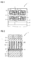
- Fig. 2 shows a schematic diagram of a section of an energy storage unit 1 according to a second embodiment of the invention.
- the energy storage unit 1 likewise consists of a first electrode 2 (negative electrode) and a second electrode 7 (positive electrode), which are separated from one another by a solid electrolyte 8 permeable to oxygen ions.
- comb-like structures in the sense of interconnectors 12, 13 are associated with both the first electrode 2 and the second electrode 7, wherein the interconnector 13 assigned to the second electrode 7 serves as a gas distributor, through whose chamber-like spaces 14 air oxygen continuously flows, which flows via the second Electrode 7 is reduced before passage through the electrolyte 8 to oxygen ions.
- the interconnectors 12, 13 are electrically connected to each other with the interposition of an electrical load (not shown).
- Fig. 2 and in particular Fig. 3 It can be seen that the chamber-like intermediate spaces 16 of the interconnector 12, which depart from the first electrode 2, are filled with the ODS particles 5 acting as energy stores of the energy storage unit 1.
- the energy storage unit 1 has a high energy storage capacity since it contains the energy store, ie the ODS particles 5 themselves.
- the invention is also directed to differently constructed energy storage units 1, for example, with an externally connected to the and via ion or electron conductor with this associated arranged memory for the ODS particles. 5
- the oxygen ions diffused by the electrolyte 8 come into contact with the porous network-like structure of the ODS particles 5.
- the oxygen ions are first reduced to elemental oxygen, which flows through the interstices of the ODS particles 5 (see arrow 17).
- the oxygen oxidizes the ODS particles 5 or the metal matrix 18 or parts thereof to corresponding metal oxides, the resulting free electrons in the discharge operation of the energy storage unit 1, the current for a consumer.
- the energy storage unit 1 is accordingly improved over the known from the prior art energy storage units 1 in particular with regard to their life or service life.
Landscapes
- Chemical & Material Sciences (AREA)
- Engineering & Computer Science (AREA)
- Chemical Kinetics & Catalysis (AREA)
- Electrochemistry (AREA)
- General Chemical & Material Sciences (AREA)
- Materials Engineering (AREA)
- Manufacturing & Machinery (AREA)
- Sustainable Energy (AREA)
- Life Sciences & Earth Sciences (AREA)
- Sustainable Development (AREA)
- Power Engineering (AREA)
- Ceramic Engineering (AREA)
- Composite Materials (AREA)
- Microelectronics & Electronic Packaging (AREA)
- Inorganic Chemistry (AREA)
- Hybrid Cells (AREA)
- Battery Electrode And Active Subsutance (AREA)
Claims (13)
- Unité d'accumulation d'énergie rechargeable, comprenant une première électrode et une deuxième électrode, des particules métalliques, en un métal réductible en fonctionnement de charge de l'unité d'accumulation d'énergie et oxydable en fonctionnement de décharge de l'unité d'accumulation d'énergie, étant associées à la première électrode et un électrolyte étant disposé entres les électrodes, caractérisée en ce que les particules métalliques contiennent supplémentairement une matière sous forme de particules d'oxyde métallique empêchant un frittage des particules métalliques.
- Unité d'accumulation d'énergie rechargeable suivant la revendication 1, caractérisée en ce que les particules d'oxyde métallique sont des particules d'oxyde de cérium et/ou d'oxyde de zirconium.
- Unité d'accumulation d'énergie rechargeable suivant la revendication 1 ou 2, caractérisée en ce que les particules ( 6 ) d'oxyde métallique sont dopées par des substances de dopage.
- Unité d'accumulation d'énergie rechargeable suivant la revendication 2 et 3, caractérisée en ce que les substances de dopage, pour l'oxyde de zirconium, sont le scandium et/ou l'yttrium et les substances de dopage, pour l'oxyde de cérium, sont le gadolinium et le samarium.
- Unité d'accumulation d'énergie rechargeable suivant l'une des revendications précédentes, caractérisée en ce que les particules métalliques sont alliées mécaniquement à la matière empêchant le frittage.
- Unité d'accumulation d'énergie rechargeable suivant l'une des revendications précédentes, caractérisée en ce que les particules métalliques ont respectivement une proportion molaire de 1 à 20%, notamment de 5 à 10%, de la matière empêchant le frittage.
- Unité d'accumulation d'énergie rechargeable suivant l'une des revendications précédentes, caractérisée en ce que les particules métalliques sont formées de fer et/ou de manganèse.
- Unité d'accumulation d'énergie rechargeable suivant l'une des revendications précédentes, caractérisée en ce que la première électrode ( 2 ) a une structure ( 3 ) à chambre creuse de type en réseau, les particules métalliques étant prévues dans les espaces ( 4 ) de réception disposés dans les espaces intermédiaires de la structure ( 3 ) de chambre creuse.
- Unité d'accumulation d'énergie rechargeable suivant l'une des revendications 1 à 8, caractérisée en ce que la première électrode ( 2 ) est reliée à une structure de type en peigne constituant des espaces ( 16 ) intermédiaires, les espaces ( 16 ) intermédiaires étant tournés vers la première électrode ( 2 ) et étant remplis des particules métalliques.
- Unité d'accumulation d'énergie rechargeable suivant l'une des revendications précédentes, caractérisée en ce qu'un mélange gazeux à activité rédox, notamment un mélange d'hydrogène et d'eau, est prévu entre les particules métalliques.
- Unité d'accumulation d'énergie rechargeable suivant l'une des revendications précédentes, caractérisée en ce que la deuxième électrode ( 7 ) est formée d'une matière poreuse perméable à l'oxygène.
- Unité d'accumulation d'énergie rechargeable suivant l'une des revendications précédentes, caractérisée en ce que l'électrolyte ( 8 ) est un électrolyte solide ayant une perméabilité aux ions oxygène.
- Accumulateur d'énergie comprenant plusieurs unités ( 1 ) d'accumulation d'énergie suivant l'une des revendications précédentes.
Applications Claiming Priority (2)
| Application Number | Priority Date | Filing Date | Title |
|---|---|---|---|
| DE201010041019 DE102010041019A1 (de) | 2010-09-20 | 2010-09-20 | Wiederaufladbare Energiespeichereinheit |
| PCT/EP2011/065947 WO2012038312A1 (fr) | 2010-09-20 | 2011-09-14 | Unité d'accumulation d'énergie rechargeable |
Publications (2)
| Publication Number | Publication Date |
|---|---|
| EP2619829A1 EP2619829A1 (fr) | 2013-07-31 |
| EP2619829B1 true EP2619829B1 (fr) | 2015-03-18 |
Family
ID=44681105
Family Applications (1)
| Application Number | Title | Priority Date | Filing Date |
|---|---|---|---|
| EP11761322.4A Not-in-force EP2619829B1 (fr) | 2010-09-20 | 2011-09-14 | Unité d'accumulation d'energie rechargeable |
Country Status (6)
| Country | Link |
|---|---|
| US (1) | US9147904B2 (fr) |
| EP (1) | EP2619829B1 (fr) |
| KR (1) | KR101863845B1 (fr) |
| DE (1) | DE102010041019A1 (fr) |
| DK (1) | DK2619829T3 (fr) |
| WO (1) | WO2012038312A1 (fr) |
Families Citing this family (11)
| Publication number | Priority date | Publication date | Assignee | Title |
|---|---|---|---|---|
| WO2013068218A1 (fr) | 2011-11-09 | 2013-05-16 | Siemens Aktiengesellschaft | Élément d'accumulation pour un accumulateur d'énergie à électrolyte solide |
| DE102012201066A1 (de) * | 2012-01-25 | 2013-07-25 | Siemens Aktiengesellschaft | Elektrischer Energiespeicher |
| DE102012211326A1 (de) * | 2012-06-29 | 2014-01-02 | Siemens Aktiengesellschaft | Speicherstruktur einer elektrischen Energiespeicherzelle |
| DE102012211325A1 (de) * | 2012-06-29 | 2014-01-02 | Siemens Aktiengesellschaft | Elektrischer Energiespeicher |
| DE102012211318A1 (de) * | 2012-06-29 | 2014-01-02 | Siemens Aktiengesellschaft | Elektrischer Energiespeicher |
| DE102012211322A1 (de) * | 2012-06-29 | 2014-01-02 | Siemens Aktiengesellschaft | Elektrischer Energiespeicher |
| DE102012211474A1 (de) * | 2012-07-03 | 2014-01-09 | Siemens Aktiengesellschaft | Speicherstruktur einer elektrischen Energiespeicherzelle |
| DE102012217290A1 (de) | 2012-09-25 | 2014-03-27 | Siemens Aktiengesellschaft | Elektrischer Energiespeicher |
| DE102013200582A1 (de) * | 2013-01-16 | 2014-07-31 | Siemens Aktiengesellschaft | Wiederaufladbarer elektrischer Energiespeicher |
| DE102013008659A1 (de) * | 2013-05-18 | 2014-11-20 | Forschungszentrum Jülich GmbH | Elektrochemisches Speichermaterial und elektrochemische Speichereinrichtung zur Speicherung elektrischer Energie, umfassend ein solches Speichermaterial |
| WO2014195099A1 (fr) * | 2013-06-04 | 2014-12-11 | Siemens Aktiengesellschaft | Structure accumulatrice et procédé de régénération d'un milieu accumulateur |
Family Cites Families (10)
| Publication number | Priority date | Publication date | Assignee | Title |
|---|---|---|---|---|
| US3310438A (en) * | 1966-02-17 | 1967-03-21 | St Joseph Lead Co | Dispersion strengthened lead battery grids |
| US3977901A (en) * | 1974-10-23 | 1976-08-31 | Westinghouse Electric Corporation | Metal/air cells and improved air electrodes for use therein |
| US5429793A (en) * | 1994-05-17 | 1995-07-04 | Institute Of Gas Technology | Scaleable process for producing Ni-Al ODS anode |
| US5976345A (en) * | 1997-01-06 | 1999-11-02 | Boston University | Method and apparatus for metal extraction and sensor device related thereto |
| US6878482B2 (en) * | 2001-06-04 | 2005-04-12 | Evionyx, Inc. | Anode structure for metal air electrochemical cells |
| JP2007258127A (ja) * | 2006-03-27 | 2007-10-04 | Sony Corp | 負極および電池 |
| KR100814880B1 (ko) * | 2006-11-22 | 2008-03-18 | 삼성에스디아이 주식회사 | 리튬 이차 전지용 음극 활물질, 이의 제조 방법 및 이를포함하는 리튬 이차 전지 |
| EP1936720B1 (fr) * | 2006-12-20 | 2011-02-23 | Samsung SDI Co., Ltd. | Électrode négative et batterie au lithium rechargeable l'incluant |
| US20090148743A1 (en) * | 2007-12-07 | 2009-06-11 | Day Michael J | High performance multilayer electrodes for use in oxygen-containing gases |
| US8304112B2 (en) * | 2008-12-01 | 2012-11-06 | Tai-Her Yang | Electrode plate multi-end sides to single end side current collector of an electricity storage/discharge device |
-
2010
- 2010-09-20 DE DE201010041019 patent/DE102010041019A1/de not_active Withdrawn
-
2011
- 2011-09-14 KR KR1020137006984A patent/KR101863845B1/ko not_active Expired - Fee Related
- 2011-09-14 WO PCT/EP2011/065947 patent/WO2012038312A1/fr not_active Ceased
- 2011-09-14 EP EP11761322.4A patent/EP2619829B1/fr not_active Not-in-force
- 2011-09-14 US US13/823,138 patent/US9147904B2/en not_active Expired - Fee Related
- 2011-09-14 DK DK11761322.4T patent/DK2619829T3/en active
Also Published As
| Publication number | Publication date |
|---|---|
| US9147904B2 (en) | 2015-09-29 |
| EP2619829A1 (fr) | 2013-07-31 |
| KR20130106822A (ko) | 2013-09-30 |
| WO2012038312A1 (fr) | 2012-03-29 |
| KR101863845B1 (ko) | 2018-06-04 |
| US20130183595A1 (en) | 2013-07-18 |
| DK2619829T3 (en) | 2015-06-01 |
| DE102010041019A1 (de) | 2012-03-22 |
Similar Documents
| Publication | Publication Date | Title |
|---|---|---|
| EP2619829B1 (fr) | Unité d'accumulation d'energie rechargeable | |
| EP2659541B1 (fr) | Cellule au lithium-soufre à base d'électrolyte solide | |
| DE3403608A1 (de) | Brennstoffzelle | |
| EP2956981B1 (fr) | Élément de conversion d'énergie comportant une unité de conversion électrochimique | |
| DE102014002451A1 (de) | Elektro-chemischer Energiespeicher sowie Verfahren zum Betreiben desselben | |
| DE102007054098A1 (de) | Elektrochemische Zelle und Brennstoffzelle diese umfassend | |
| EP2850676B1 (fr) | Structure accumulatrice d'un élément accumulateur d'énergie électrique | |
| EP2671282B1 (fr) | Accumulateur d'énergie électrique | |
| DE102011083545A1 (de) | Speicherelement | |
| DE102009056457A1 (de) | Anodenmaterialien für PEM-Brennstoffzellen | |
| DE102013013784B4 (de) | Anordnung zur Speicherung von Energie sowie Vorrichtung und Verfahren zur Bereitstellung elektrischer Energie | |
| AT528030B1 (de) | Sauerstoffionenbatterie | |
| DE19812512C2 (de) | Kathode für eine Schmelzkarbonatbrennstoffzelle sowie Schmelzkarbonatbrennstoffzelle mit einer solchen Kathode | |
| DE19817615C1 (de) | La¶0¶¶.¶¶9¶Sr¶0¶¶.¶¶1¶(Ga¶1¶¶-¶¶y¶M¶y¶)¶0¶¶.¶¶8¶Mg¶0¶¶.¶¶2¶O¶3¶¶-¶¶x¶-Werkstoff für HT-BZ | |
| DE102012213037A1 (de) | Speichereinrichtung für elektrische Energie, insbesondere Batterie oder Batteriezelle | |
| DE112013003487T5 (de) | Reduzieren der begrenzung von sauerstoff- und elektrolyttransport in der lithium/ sauerstoffbatterie durch elektrodendesign und benetzungssteuerung | |
| DE102012223794A1 (de) | Wiederaufladbarer elektrischer Energiespeicher, insbesondere in Form eines Metalloxid-Luft-Energiespeichers, mit wenigstens einem wenigstens ein Speichermaterial zur Speicherung elektrischer Energie umfassenden Speicherelement | |
| DE112023005094T5 (de) | Elektrochemische Zelle | |
| DE102017100738A1 (de) | Brennstoffzellenstapel mit erhöhter Beständigkeit gegenüber Spannungsumkehr sowie Brennstoffzellensystem und Fahrzeug mit einem solchen | |
| DE102013200759A1 (de) | Wiederaufladbarer elektrischer Energiespeicher | |
| DE102012211325A1 (de) | Elektrischer Energiespeicher | |
| DE102013200585A1 (de) | Wiederaufladbarer elektrischer Energiespeicher | |
| EP2724401A1 (fr) | Élément accumulateur | |
| DE102013200582A1 (de) | Wiederaufladbarer elektrischer Energiespeicher | |
| DE102017220554A1 (de) | Kohlenstoff geträgerter Edelmetallkatalysator, Elektrodenstruktur, Brennstoffzelle sowie Brennstoffzellensystem |
Legal Events
| Date | Code | Title | Description |
|---|---|---|---|
| PUAI | Public reference made under article 153(3) epc to a published international application that has entered the european phase |
Free format text: ORIGINAL CODE: 0009012 |
|
| 17P | Request for examination filed |
Effective date: 20130315 |
|
| AK | Designated contracting states |
Kind code of ref document: A1 Designated state(s): AL AT BE BG CH CY CZ DE DK EE ES FI FR GB GR HR HU IE IS IT LI LT LU LV MC MK MT NL NO PL PT RO RS SE SI SK SM TR |
|
| RIN1 | Information on inventor provided before grant (corrected) |
Inventor name: ZAMPIERI, ALESSANDRO Inventor name: GREINER, HORST |
|
| DAX | Request for extension of the european patent (deleted) | ||
| REG | Reference to a national code |
Ref country code: DE Ref legal event code: R079 Ref document number: 502011006321 Country of ref document: DE Free format text: PREVIOUS MAIN CLASS: H01M0004240000 Ipc: H01M0004900000 |
|
| GRAP | Despatch of communication of intention to grant a patent |
Free format text: ORIGINAL CODE: EPIDOSNIGR1 |
|
| RIC1 | Information provided on ipc code assigned before grant |
Ipc: H01M 4/86 20060101ALI20140902BHEP Ipc: H01M 4/90 20060101AFI20140902BHEP |
|
| INTG | Intention to grant announced |
Effective date: 20141008 |
|
| GRAS | Grant fee paid |
Free format text: ORIGINAL CODE: EPIDOSNIGR3 |
|
| GRAA | (expected) grant |
Free format text: ORIGINAL CODE: 0009210 |
|
| AK | Designated contracting states |
Kind code of ref document: B1 Designated state(s): AL AT BE BG CH CY CZ DE DK EE ES FI FR GB GR HR HU IE IS IT LI LT LU LV MC MK MT NL NO PL PT RO RS SE SI SK SM TR |
|
| REG | Reference to a national code |
Ref country code: GB Ref legal event code: FG4D Free format text: NOT ENGLISH |
|
| REG | Reference to a national code |
Ref country code: CH Ref legal event code: NV Representative=s name: SIEMENS SCHWEIZ AG, CH Ref country code: CH Ref legal event code: EP |
|
| REG | Reference to a national code |
Ref country code: IE Ref legal event code: FG4D Free format text: LANGUAGE OF EP DOCUMENT: GERMAN |
|
| REG | Reference to a national code |
Ref country code: AT Ref legal event code: REF Ref document number: 717077 Country of ref document: AT Kind code of ref document: T Effective date: 20150415 |
|
| REG | Reference to a national code |
Ref country code: DE Ref legal event code: R096 Ref document number: 502011006321 Country of ref document: DE Effective date: 20150423 |
|
| REG | Reference to a national code |
Ref country code: DK Ref legal event code: T3 Effective date: 20150526 |
|
| REG | Reference to a national code |
Ref country code: NL Ref legal event code: VDEP Effective date: 20150318 |
|
| REG | Reference to a national code |
Ref country code: NL Ref legal event code: VDEP Effective date: 20150318 |
|
| PG25 | Lapsed in a contracting state [announced via postgrant information from national office to epo] |
Ref country code: NO Free format text: LAPSE BECAUSE OF FAILURE TO SUBMIT A TRANSLATION OF THE DESCRIPTION OR TO PAY THE FEE WITHIN THE PRESCRIBED TIME-LIMIT Effective date: 20150618 Ref country code: FI Free format text: LAPSE BECAUSE OF FAILURE TO SUBMIT A TRANSLATION OF THE DESCRIPTION OR TO PAY THE FEE WITHIN THE PRESCRIBED TIME-LIMIT Effective date: 20150318 Ref country code: SE Free format text: LAPSE BECAUSE OF FAILURE TO SUBMIT A TRANSLATION OF THE DESCRIPTION OR TO PAY THE FEE WITHIN THE PRESCRIBED TIME-LIMIT Effective date: 20150318 Ref country code: LT Free format text: LAPSE BECAUSE OF FAILURE TO SUBMIT A TRANSLATION OF THE DESCRIPTION OR TO PAY THE FEE WITHIN THE PRESCRIBED TIME-LIMIT Effective date: 20150318 Ref country code: HR Free format text: LAPSE BECAUSE OF FAILURE TO SUBMIT A TRANSLATION OF THE DESCRIPTION OR TO PAY THE FEE WITHIN THE PRESCRIBED TIME-LIMIT Effective date: 20150318 |
|
| REG | Reference to a national code |
Ref country code: LT Ref legal event code: MG4D |
|
| PG25 | Lapsed in a contracting state [announced via postgrant information from national office to epo] |
Ref country code: RS Free format text: LAPSE BECAUSE OF FAILURE TO SUBMIT A TRANSLATION OF THE DESCRIPTION OR TO PAY THE FEE WITHIN THE PRESCRIBED TIME-LIMIT Effective date: 20150318 Ref country code: GR Free format text: LAPSE BECAUSE OF FAILURE TO SUBMIT A TRANSLATION OF THE DESCRIPTION OR TO PAY THE FEE WITHIN THE PRESCRIBED TIME-LIMIT Effective date: 20150619 Ref country code: LV Free format text: LAPSE BECAUSE OF FAILURE TO SUBMIT A TRANSLATION OF THE DESCRIPTION OR TO PAY THE FEE WITHIN THE PRESCRIBED TIME-LIMIT Effective date: 20150318 |
|
| PG25 | Lapsed in a contracting state [announced via postgrant information from national office to epo] |
Ref country code: NL Free format text: LAPSE BECAUSE OF FAILURE TO SUBMIT A TRANSLATION OF THE DESCRIPTION OR TO PAY THE FEE WITHIN THE PRESCRIBED TIME-LIMIT Effective date: 20150318 |
|
| PG25 | Lapsed in a contracting state [announced via postgrant information from national office to epo] |
Ref country code: PT Free format text: LAPSE BECAUSE OF FAILURE TO SUBMIT A TRANSLATION OF THE DESCRIPTION OR TO PAY THE FEE WITHIN THE PRESCRIBED TIME-LIMIT Effective date: 20150720 Ref country code: RO Free format text: LAPSE BECAUSE OF FAILURE TO SUBMIT A TRANSLATION OF THE DESCRIPTION OR TO PAY THE FEE WITHIN THE PRESCRIBED TIME-LIMIT Effective date: 20150318 Ref country code: CZ Free format text: LAPSE BECAUSE OF FAILURE TO SUBMIT A TRANSLATION OF THE DESCRIPTION OR TO PAY THE FEE WITHIN THE PRESCRIBED TIME-LIMIT Effective date: 20150318 Ref country code: EE Free format text: LAPSE BECAUSE OF FAILURE TO SUBMIT A TRANSLATION OF THE DESCRIPTION OR TO PAY THE FEE WITHIN THE PRESCRIBED TIME-LIMIT Effective date: 20150318 Ref country code: ES Free format text: LAPSE BECAUSE OF FAILURE TO SUBMIT A TRANSLATION OF THE DESCRIPTION OR TO PAY THE FEE WITHIN THE PRESCRIBED TIME-LIMIT Effective date: 20150318 Ref country code: SK Free format text: LAPSE BECAUSE OF FAILURE TO SUBMIT A TRANSLATION OF THE DESCRIPTION OR TO PAY THE FEE WITHIN THE PRESCRIBED TIME-LIMIT Effective date: 20150318 |
|
| PG25 | Lapsed in a contracting state [announced via postgrant information from national office to epo] |
Ref country code: IS Free format text: LAPSE BECAUSE OF FAILURE TO SUBMIT A TRANSLATION OF THE DESCRIPTION OR TO PAY THE FEE WITHIN THE PRESCRIBED TIME-LIMIT Effective date: 20150718 Ref country code: PL Free format text: LAPSE BECAUSE OF FAILURE TO SUBMIT A TRANSLATION OF THE DESCRIPTION OR TO PAY THE FEE WITHIN THE PRESCRIBED TIME-LIMIT Effective date: 20150318 |
|
| REG | Reference to a national code |
Ref country code: DE Ref legal event code: R097 Ref document number: 502011006321 Country of ref document: DE |
|
| PG25 | Lapsed in a contracting state [announced via postgrant information from national office to epo] |
Ref country code: IT Free format text: LAPSE BECAUSE OF FAILURE TO SUBMIT A TRANSLATION OF THE DESCRIPTION OR TO PAY THE FEE WITHIN THE PRESCRIBED TIME-LIMIT Effective date: 20150318 |
|
| PLBE | No opposition filed within time limit |
Free format text: ORIGINAL CODE: 0009261 |
|
| STAA | Information on the status of an ep patent application or granted ep patent |
Free format text: STATUS: NO OPPOSITION FILED WITHIN TIME LIMIT |
|
| 26N | No opposition filed |
Effective date: 20151221 |
|
| PG25 | Lapsed in a contracting state [announced via postgrant information from national office to epo] |
Ref country code: SI Free format text: LAPSE BECAUSE OF FAILURE TO SUBMIT A TRANSLATION OF THE DESCRIPTION OR TO PAY THE FEE WITHIN THE PRESCRIBED TIME-LIMIT Effective date: 20150318 |
|
| PG25 | Lapsed in a contracting state [announced via postgrant information from national office to epo] |
Ref country code: MC Free format text: LAPSE BECAUSE OF FAILURE TO SUBMIT A TRANSLATION OF THE DESCRIPTION OR TO PAY THE FEE WITHIN THE PRESCRIBED TIME-LIMIT Effective date: 20150318 Ref country code: LU Free format text: LAPSE BECAUSE OF FAILURE TO SUBMIT A TRANSLATION OF THE DESCRIPTION OR TO PAY THE FEE WITHIN THE PRESCRIBED TIME-LIMIT Effective date: 20150914 |
|
| REG | Reference to a national code |
Ref country code: IE Ref legal event code: MM4A |
|
| PG25 | Lapsed in a contracting state [announced via postgrant information from national office to epo] |
Ref country code: IE Free format text: LAPSE BECAUSE OF NON-PAYMENT OF DUE FEES Effective date: 20150914 |
|
| REG | Reference to a national code |
Ref country code: FR Ref legal event code: PLFP Year of fee payment: 6 |
|
| PG25 | Lapsed in a contracting state [announced via postgrant information from national office to epo] |
Ref country code: MT Free format text: LAPSE BECAUSE OF FAILURE TO SUBMIT A TRANSLATION OF THE DESCRIPTION OR TO PAY THE FEE WITHIN THE PRESCRIBED TIME-LIMIT Effective date: 20150318 |
|
| PG25 | Lapsed in a contracting state [announced via postgrant information from national office to epo] |
Ref country code: SM Free format text: LAPSE BECAUSE OF FAILURE TO SUBMIT A TRANSLATION OF THE DESCRIPTION OR TO PAY THE FEE WITHIN THE PRESCRIBED TIME-LIMIT Effective date: 20150318 Ref country code: BG Free format text: LAPSE BECAUSE OF FAILURE TO SUBMIT A TRANSLATION OF THE DESCRIPTION OR TO PAY THE FEE WITHIN THE PRESCRIBED TIME-LIMIT Effective date: 20150318 Ref country code: HU Free format text: LAPSE BECAUSE OF FAILURE TO SUBMIT A TRANSLATION OF THE DESCRIPTION OR TO PAY THE FEE WITHIN THE PRESCRIBED TIME-LIMIT; INVALID AB INITIO Effective date: 20110914 |
|
| PG25 | Lapsed in a contracting state [announced via postgrant information from national office to epo] |
Ref country code: CY Free format text: LAPSE BECAUSE OF FAILURE TO SUBMIT A TRANSLATION OF THE DESCRIPTION OR TO PAY THE FEE WITHIN THE PRESCRIBED TIME-LIMIT Effective date: 20150318 |
|
| PG25 | Lapsed in a contracting state [announced via postgrant information from national office to epo] |
Ref country code: BE Free format text: LAPSE BECAUSE OF NON-PAYMENT OF DUE FEES Effective date: 20150930 |
|
| REG | Reference to a national code |
Ref country code: FR Ref legal event code: PLFP Year of fee payment: 7 |
|
| REG | Reference to a national code |
Ref country code: CH Ref legal event code: PCOW Free format text: NEW ADDRESS: WERNER-VON-SIEMENS-STRASSE 1, 80333 MUENCHEN (DE) |
|
| PG25 | Lapsed in a contracting state [announced via postgrant information from national office to epo] |
Ref country code: MK Free format text: LAPSE BECAUSE OF FAILURE TO SUBMIT A TRANSLATION OF THE DESCRIPTION OR TO PAY THE FEE WITHIN THE PRESCRIBED TIME-LIMIT Effective date: 20150318 Ref country code: TR Free format text: LAPSE BECAUSE OF FAILURE TO SUBMIT A TRANSLATION OF THE DESCRIPTION OR TO PAY THE FEE WITHIN THE PRESCRIBED TIME-LIMIT Effective date: 20150318 |
|
| REG | Reference to a national code |
Ref country code: FR Ref legal event code: PLFP Year of fee payment: 8 |
|
| PG25 | Lapsed in a contracting state [announced via postgrant information from national office to epo] |
Ref country code: AL Free format text: LAPSE BECAUSE OF FAILURE TO SUBMIT A TRANSLATION OF THE DESCRIPTION OR TO PAY THE FEE WITHIN THE PRESCRIBED TIME-LIMIT Effective date: 20150318 |
|
| PGFP | Annual fee paid to national office [announced via postgrant information from national office to epo] |
Ref country code: FR Payment date: 20180924 Year of fee payment: 8 |
|
| PGFP | Annual fee paid to national office [announced via postgrant information from national office to epo] |
Ref country code: DK Payment date: 20180921 Year of fee payment: 8 Ref country code: AT Payment date: 20180806 Year of fee payment: 8 Ref country code: GB Payment date: 20180911 Year of fee payment: 8 |
|
| PGFP | Annual fee paid to national office [announced via postgrant information from national office to epo] |
Ref country code: DE Payment date: 20181119 Year of fee payment: 8 |
|
| PGFP | Annual fee paid to national office [announced via postgrant information from national office to epo] |
Ref country code: CH Payment date: 20181210 Year of fee payment: 8 |
|
| REG | Reference to a national code |
Ref country code: DE Ref legal event code: R119 Ref document number: 502011006321 Country of ref document: DE |
|
| REG | Reference to a national code |
Ref country code: DK Ref legal event code: EBP Effective date: 20190930 |
|
| REG | Reference to a national code |
Ref country code: CH Ref legal event code: PL |
|
| PG25 | Lapsed in a contracting state [announced via postgrant information from national office to epo] |
Ref country code: CH Free format text: LAPSE BECAUSE OF NON-PAYMENT OF DUE FEES Effective date: 20190930 Ref country code: DE Free format text: LAPSE BECAUSE OF NON-PAYMENT OF DUE FEES Effective date: 20200401 Ref country code: LI Free format text: LAPSE BECAUSE OF NON-PAYMENT OF DUE FEES Effective date: 20190930 |
|
| REG | Reference to a national code |
Ref country code: AT Ref legal event code: MM01 Ref document number: 717077 Country of ref document: AT Kind code of ref document: T Effective date: 20190914 |
|
| GBPC | Gb: european patent ceased through non-payment of renewal fee |
Effective date: 20190914 |
|
| PG25 | Lapsed in a contracting state [announced via postgrant information from national office to epo] |
Ref country code: GB Free format text: LAPSE BECAUSE OF NON-PAYMENT OF DUE FEES Effective date: 20190914 Ref country code: DK Free format text: LAPSE BECAUSE OF NON-PAYMENT OF DUE FEES Effective date: 20190930 |
|
| PG25 | Lapsed in a contracting state [announced via postgrant information from national office to epo] |
Ref country code: AT Free format text: LAPSE BECAUSE OF NON-PAYMENT OF DUE FEES Effective date: 20190914 |
|
| PG25 | Lapsed in a contracting state [announced via postgrant information from national office to epo] |
Ref country code: FR Free format text: LAPSE BECAUSE OF NON-PAYMENT OF DUE FEES Effective date: 20190930 |