EP2618988B1 - Rapid manufacturing method and apparatus - Google Patents
Rapid manufacturing method and apparatus Download PDFInfo
- Publication number
- EP2618988B1 EP2618988B1 EP11749287.6A EP11749287A EP2618988B1 EP 2618988 B1 EP2618988 B1 EP 2618988B1 EP 11749287 A EP11749287 A EP 11749287A EP 2618988 B1 EP2618988 B1 EP 2618988B1
- Authority
- EP
- European Patent Office
- Prior art keywords
- precursor material
- base structure
- frame
- layer
- new
- Prior art date
- Legal status (The legal status is an assumption and is not a legal conclusion. Google has not performed a legal analysis and makes no representation as to the accuracy of the status listed.)
- Active
Links
Images


Classifications
-
- B—PERFORMING OPERATIONS; TRANSPORTING
- B22—CASTING; POWDER METALLURGY
- B22F—WORKING METALLIC POWDER; MANUFACTURE OF ARTICLES FROM METALLIC POWDER; MAKING METALLIC POWDER; APPARATUS OR DEVICES SPECIALLY ADAPTED FOR METALLIC POWDER
- B22F10/00—Additive manufacturing of workpieces or articles from metallic powder
-
- B—PERFORMING OPERATIONS; TRANSPORTING
- B29—WORKING OF PLASTICS; WORKING OF SUBSTANCES IN A PLASTIC STATE IN GENERAL
- B29C—SHAPING OR JOINING OF PLASTICS; SHAPING OF MATERIAL IN A PLASTIC STATE, NOT OTHERWISE PROVIDED FOR; AFTER-TREATMENT OF THE SHAPED PRODUCTS, e.g. REPAIRING
- B29C64/00—Additive manufacturing, i.e. manufacturing of three-dimensional [3D] objects by additive deposition, additive agglomeration or additive layering, e.g. by 3D printing, stereolithography or selective laser sintering
- B29C64/30—Auxiliary operations or equipment
- B29C64/35—Cleaning
-
- B—PERFORMING OPERATIONS; TRANSPORTING
- B22—CASTING; POWDER METALLURGY
- B22F—WORKING METALLIC POWDER; MANUFACTURE OF ARTICLES FROM METALLIC POWDER; MAKING METALLIC POWDER; APPARATUS OR DEVICES SPECIALLY ADAPTED FOR METALLIC POWDER
- B22F10/00—Additive manufacturing of workpieces or articles from metallic powder
- B22F10/20—Direct sintering or melting
- B22F10/28—Powder bed fusion, e.g. selective laser melting [SLM] or electron beam melting [EBM]
-
- B—PERFORMING OPERATIONS; TRANSPORTING
- B22—CASTING; POWDER METALLURGY
- B22F—WORKING METALLIC POWDER; MANUFACTURE OF ARTICLES FROM METALLIC POWDER; MAKING METALLIC POWDER; APPARATUS OR DEVICES SPECIALLY ADAPTED FOR METALLIC POWDER
- B22F10/00—Additive manufacturing of workpieces or articles from metallic powder
- B22F10/70—Recycling
- B22F10/73—Recycling of powder
-
- B—PERFORMING OPERATIONS; TRANSPORTING
- B22—CASTING; POWDER METALLURGY
- B22F—WORKING METALLIC POWDER; MANUFACTURE OF ARTICLES FROM METALLIC POWDER; MAKING METALLIC POWDER; APPARATUS OR DEVICES SPECIALLY ADAPTED FOR METALLIC POWDER
- B22F12/00—Apparatus or devices specially adapted for additive manufacturing; Auxiliary means for additive manufacturing; Combinations of additive manufacturing apparatus or devices with other processing apparatus or devices
- B22F12/22—Driving means
- B22F12/224—Driving means for motion along a direction within the plane of a layer
-
- B—PERFORMING OPERATIONS; TRANSPORTING
- B22—CASTING; POWDER METALLURGY
- B22F—WORKING METALLIC POWDER; MANUFACTURE OF ARTICLES FROM METALLIC POWDER; MAKING METALLIC POWDER; APPARATUS OR DEVICES SPECIALLY ADAPTED FOR METALLIC POWDER
- B22F12/00—Apparatus or devices specially adapted for additive manufacturing; Auxiliary means for additive manufacturing; Combinations of additive manufacturing apparatus or devices with other processing apparatus or devices
- B22F12/30—Platforms or substrates
- B22F12/33—Platforms or substrates translatory in the deposition plane
-
- B—PERFORMING OPERATIONS; TRANSPORTING
- B22—CASTING; POWDER METALLURGY
- B22F—WORKING METALLIC POWDER; MANUFACTURE OF ARTICLES FROM METALLIC POWDER; MAKING METALLIC POWDER; APPARATUS OR DEVICES SPECIALLY ADAPTED FOR METALLIC POWDER
- B22F12/00—Apparatus or devices specially adapted for additive manufacturing; Auxiliary means for additive manufacturing; Combinations of additive manufacturing apparatus or devices with other processing apparatus or devices
- B22F12/50—Means for feeding of material, e.g. heads
-
- B—PERFORMING OPERATIONS; TRANSPORTING
- B28—WORKING CEMENT, CLAY, OR STONE
- B28B—SHAPING CLAY OR OTHER CERAMIC COMPOSITIONS; SHAPING SLAG; SHAPING MIXTURES CONTAINING CEMENTITIOUS MATERIAL, e.g. PLASTER
- B28B1/00—Producing shaped prefabricated articles from the material
- B28B1/001—Rapid manufacturing of 3D objects by additive depositing, agglomerating or laminating of material
-
- B—PERFORMING OPERATIONS; TRANSPORTING
- B28—WORKING CEMENT, CLAY, OR STONE
- B28B—SHAPING CLAY OR OTHER CERAMIC COMPOSITIONS; SHAPING SLAG; SHAPING MIXTURES CONTAINING CEMENTITIOUS MATERIAL, e.g. PLASTER
- B28B17/00—Details of, or accessories for, apparatus for shaping the material; Auxiliary measures taken in connection with such shaping
- B28B17/0063—Control arrangements
- B28B17/0081—Process control
-
- B—PERFORMING OPERATIONS; TRANSPORTING
- B29—WORKING OF PLASTICS; WORKING OF SUBSTANCES IN A PLASTIC STATE IN GENERAL
- B29C—SHAPING OR JOINING OF PLASTICS; SHAPING OF MATERIAL IN A PLASTIC STATE, NOT OTHERWISE PROVIDED FOR; AFTER-TREATMENT OF THE SHAPED PRODUCTS, e.g. REPAIRING
- B29C64/00—Additive manufacturing, i.e. manufacturing of three-dimensional [3D] objects by additive deposition, additive agglomeration or additive layering, e.g. by 3D printing, stereolithography or selective laser sintering
- B29C64/10—Processes of additive manufacturing
- B29C64/141—Processes of additive manufacturing using only solid materials
- B29C64/153—Processes of additive manufacturing using only solid materials using layers of powder being selectively joined, e.g. by selective laser sintering or melting
-
- B—PERFORMING OPERATIONS; TRANSPORTING
- B29—WORKING OF PLASTICS; WORKING OF SUBSTANCES IN A PLASTIC STATE IN GENERAL
- B29C—SHAPING OR JOINING OF PLASTICS; SHAPING OF MATERIAL IN A PLASTIC STATE, NOT OTHERWISE PROVIDED FOR; AFTER-TREATMENT OF THE SHAPED PRODUCTS, e.g. REPAIRING
- B29C64/00—Additive manufacturing, i.e. manufacturing of three-dimensional [3D] objects by additive deposition, additive agglomeration or additive layering, e.g. by 3D printing, stereolithography or selective laser sintering
- B29C64/30—Auxiliary operations or equipment
- B29C64/357—Recycling
-
- B—PERFORMING OPERATIONS; TRANSPORTING
- B29—WORKING OF PLASTICS; WORKING OF SUBSTANCES IN A PLASTIC STATE IN GENERAL
- B29C—SHAPING OR JOINING OF PLASTICS; SHAPING OF MATERIAL IN A PLASTIC STATE, NOT OTHERWISE PROVIDED FOR; AFTER-TREATMENT OF THE SHAPED PRODUCTS, e.g. REPAIRING
- B29C64/00—Additive manufacturing, i.e. manufacturing of three-dimensional [3D] objects by additive deposition, additive agglomeration or additive layering, e.g. by 3D printing, stereolithography or selective laser sintering
- B29C64/30—Auxiliary operations or equipment
- B29C64/386—Data acquisition or data processing for additive manufacturing
- B29C64/393—Data acquisition or data processing for additive manufacturing for controlling or regulating additive manufacturing processes
-
- B—PERFORMING OPERATIONS; TRANSPORTING
- B29—WORKING OF PLASTICS; WORKING OF SUBSTANCES IN A PLASTIC STATE IN GENERAL
- B29C—SHAPING OR JOINING OF PLASTICS; SHAPING OF MATERIAL IN A PLASTIC STATE, NOT OTHERWISE PROVIDED FOR; AFTER-TREATMENT OF THE SHAPED PRODUCTS, e.g. REPAIRING
- B29C64/00—Additive manufacturing, i.e. manufacturing of three-dimensional [3D] objects by additive deposition, additive agglomeration or additive layering, e.g. by 3D printing, stereolithography or selective laser sintering
- B29C64/40—Structures for supporting 3D objects during manufacture and intended to be sacrificed after completion thereof
-
- B—PERFORMING OPERATIONS; TRANSPORTING
- B33—ADDITIVE MANUFACTURING TECHNOLOGY
- B33Y—ADDITIVE MANUFACTURING, i.e. MANUFACTURING OF THREE-DIMENSIONAL [3-D] OBJECTS BY ADDITIVE DEPOSITION, ADDITIVE AGGLOMERATION OR ADDITIVE LAYERING, e.g. BY 3-D PRINTING, STEREOLITHOGRAPHY OR SELECTIVE LASER SINTERING
- B33Y10/00—Processes of additive manufacturing
-
- B—PERFORMING OPERATIONS; TRANSPORTING
- B33—ADDITIVE MANUFACTURING TECHNOLOGY
- B33Y—ADDITIVE MANUFACTURING, i.e. MANUFACTURING OF THREE-DIMENSIONAL [3-D] OBJECTS BY ADDITIVE DEPOSITION, ADDITIVE AGGLOMERATION OR ADDITIVE LAYERING, e.g. BY 3-D PRINTING, STEREOLITHOGRAPHY OR SELECTIVE LASER SINTERING
- B33Y30/00—Apparatus for additive manufacturing; Details thereof or accessories therefor
-
- B—PERFORMING OPERATIONS; TRANSPORTING
- B33—ADDITIVE MANUFACTURING TECHNOLOGY
- B33Y—ADDITIVE MANUFACTURING, i.e. MANUFACTURING OF THREE-DIMENSIONAL [3-D] OBJECTS BY ADDITIVE DEPOSITION, ADDITIVE AGGLOMERATION OR ADDITIVE LAYERING, e.g. BY 3-D PRINTING, STEREOLITHOGRAPHY OR SELECTIVE LASER SINTERING
- B33Y40/00—Auxiliary operations or equipment, e.g. for material handling
-
- B—PERFORMING OPERATIONS; TRANSPORTING
- B33—ADDITIVE MANUFACTURING TECHNOLOGY
- B33Y—ADDITIVE MANUFACTURING, i.e. MANUFACTURING OF THREE-DIMENSIONAL [3-D] OBJECTS BY ADDITIVE DEPOSITION, ADDITIVE AGGLOMERATION OR ADDITIVE LAYERING, e.g. BY 3-D PRINTING, STEREOLITHOGRAPHY OR SELECTIVE LASER SINTERING
- B33Y50/00—Data acquisition or data processing for additive manufacturing
- B33Y50/02—Data acquisition or data processing for additive manufacturing for controlling or regulating additive manufacturing processes
-
- B—PERFORMING OPERATIONS; TRANSPORTING
- B22—CASTING; POWDER METALLURGY
- B22F—WORKING METALLIC POWDER; MANUFACTURE OF ARTICLES FROM METALLIC POWDER; MAKING METALLIC POWDER; APPARATUS OR DEVICES SPECIALLY ADAPTED FOR METALLIC POWDER
- B22F10/00—Additive manufacturing of workpieces or articles from metallic powder
- B22F10/30—Process control
- B22F10/32—Process control of the atmosphere, e.g. composition or pressure in a building chamber
- B22F10/322—Process control of the atmosphere, e.g. composition or pressure in a building chamber of the gas flow, e.g. rate or direction
-
- B—PERFORMING OPERATIONS; TRANSPORTING
- B22—CASTING; POWDER METALLURGY
- B22F—WORKING METALLIC POWDER; MANUFACTURE OF ARTICLES FROM METALLIC POWDER; MAKING METALLIC POWDER; APPARATUS OR DEVICES SPECIALLY ADAPTED FOR METALLIC POWDER
- B22F12/00—Apparatus or devices specially adapted for additive manufacturing; Auxiliary means for additive manufacturing; Combinations of additive manufacturing apparatus or devices with other processing apparatus or devices
- B22F12/10—Auxiliary heating means
-
- B—PERFORMING OPERATIONS; TRANSPORTING
- B22—CASTING; POWDER METALLURGY
- B22F—WORKING METALLIC POWDER; MANUFACTURE OF ARTICLES FROM METALLIC POWDER; MAKING METALLIC POWDER; APPARATUS OR DEVICES SPECIALLY ADAPTED FOR METALLIC POWDER
- B22F12/00—Apparatus or devices specially adapted for additive manufacturing; Auxiliary means for additive manufacturing; Combinations of additive manufacturing apparatus or devices with other processing apparatus or devices
- B22F12/20—Cooling means
-
- Y—GENERAL TAGGING OF NEW TECHNOLOGICAL DEVELOPMENTS; GENERAL TAGGING OF CROSS-SECTIONAL TECHNOLOGIES SPANNING OVER SEVERAL SECTIONS OF THE IPC; TECHNICAL SUBJECTS COVERED BY FORMER USPC CROSS-REFERENCE ART COLLECTIONS [XRACs] AND DIGESTS
- Y02—TECHNOLOGIES OR APPLICATIONS FOR MITIGATION OR ADAPTATION AGAINST CLIMATE CHANGE
- Y02P—CLIMATE CHANGE MITIGATION TECHNOLOGIES IN THE PRODUCTION OR PROCESSING OF GOODS
- Y02P10/00—Technologies related to metal processing
- Y02P10/25—Process efficiency
Definitions
- Manufacturing of objects may be performed in a number of different ways.
- objects such as aircraft parts, may be manufactured using additive manufacturing.
- Additive manufacturing may be a process of joining materials to make objects. These objects may be made by using models of the desired object.
- Additive manufacturing may be performed using various technologies.
- an aerosol jetting system may send a stream of particles towards a substrate.
- the particles on the substrate may be heated to a temperature to cause the particles to adhere to each other.
- electron beams may be used to melt a metal powder layer in a desired pattern. Additional layers may be placed and melted on the layers to form the object.
- a laser system may direct a laser beam to selectively heat portions of the layer of powder to form a portion of the object. Additional layers of powder may be placed on the prior layers and heated to form the object.
- additive manufacturing may not be realized as often as desired.
- more traditional manufacturing systems such as the use of molds to form parts or dyes for use with presses, may be employed. These types of systems, however, may have undesired lead times to form the molds and dies, as well as the expense of specialized equipment to manufacture the parts.
- DE19507881 teaches a method of supporting an object made by stereolithography or another rapid prototype production method, in which a support is provided with at least one supporting structure which is airier than a supporting structure made of solid standing walls, including those made with notches at the top and/or at the bottom.
- the supporting structure can be made airy by using walls of which at least a number are provided with openings over a major part of their surface.
- a method may be present for forming objects.
- Layers of precursor material may be placed on top of each other.
- the layers of precursor material may be selectively cured as the layers of precursor material are placed on top of each other to form an object and a frame associated with the object.
- a method may be present for forming aircraft parts.
- Layers of precursor material may be placed on a base structure for a frame.
- the layers of precursor material may be selected from one of a powder, a liquid, a metal powder, a ceramic powder, and a plastic powder.
- the layers of precursor material may be selectively cured using a curing system after placing the layers of precursor material on the base structure to form a portion of an aircraft part and a portion of the frame to form a prior layer of precursor material.
- the curing system may be selected from one of a heating system, a laser, and an electron beam.
- the frame may be moved to allow a new layer of precursor material to be placed on the prior layer of precursor material in the layers of precursor material that may have been selectively cured.
- the new layer of precursor material may be placed on the prior layer of precursor material.
- a determination may be made as to whether a new base structure in the frame is needed.
- the new layer of precursor material may be selectively cured to form an additional portion of the aircraft part and a portion of the new base structure in response to the determination that the new base structure is needed.
- the steps of moving the frame to allow the new layer of precursor material to be placed on the prior layer of precursor material in the layers of precursor material that has been selectively cured, placing the new layer of precursor material on the prior layer of precursor material, and selectively curing the new layer of precursor material to form a portion of the object and the portion of the new base structure may be repeated until the base structure is completed.
- the new layer of precursor material may be selectively cured to form the additional portion of the aircraft part without forming the new base structure.
- the steps of moving the frame to allow the new layer of precursor material to be placed on the prior layer of precursor material in the layers of precursor material that has been selectively cured, placing the new layer of precursor material on the prior layer of precursor material, and selectively curing the new layer of precursor material to form the portion of the object without the new base structure may be repeated until the new base structure is needed.
- a desired temperature for the portion of the aircraft part may be maintained in different locations in the chamber as the aircraft part is formed using a plurality of heating and cooling elements.
- the uncured precursor material may be cooled to change a density of the uncured precursor material such that a flow of gas through the precursor material is reduced.
- Each portion of the aircraft part may be separated from an associated base structure connected to each portion of the aircraft part using a separation system.
- an apparatus may comprise a chamber, a curing system, and a movement system.
- the curing system may be configured to cure portions of layers of precursor material deposited in the chamber to form an object and a frame connected to the object.
- the movement system may be configured to engage the frame and move the frame and the object connected to the frame as a new layer of precursor material is placed on a prior layer of precursor material.
- a laser sintering apparatus may comprise a chamber, a curing system, a movement system, a precursor deposition system, a temperature control system, a separation system, and a recycling system.
- the curing system may be configured to cure portions of layers of precursor material deposited in the chamber to form an aircraft part and a frame connected to the aircraft part.
- the frame may comprise a plurality of base structures and a plurality of connectors and may be configured to support the aircraft part during formation of the aircraft part in the chamber.
- the curing system may be selected from at least one of a heating system, a laser, and an electron beam.
- the movement system may be configured to engage the frame and move the frame connected to the aircraft part as a new layer of precursor material may be placed on a prior layer of precursor material.
- the movement system may comprise a plurality of gears having first teeth configured to engage second teeth formed on sides of the plurality of base structures.
- the precursor deposition system may be configured to deposit the new layer of precursor material on the prior layer of precursor material.
- the temperature control system may be configured to control a temperature of at least one of the aircraft part and the frame.
- the temperature control system may comprise a plurality of heating and cooling elements configured to heat and cool walls of a chamber to control the temperature of at least one of the aircraft part and the frame and in which the temperature control system may be configured to cool uncured precursor material that has been deposited to change a density of the uncured precursor material such a flow of gas through the precursor material is reduced.
- the separation system may be configured to separate the aircraft part from a base structure.
- the separation system may be configured to separate the aircraft part from the base structure as the base structure and the aircraft part are moved by the movement system.
- the recycling system may be configured to recycle portions of the layers of precursor material that remain uncured.
- the layers of precursor material may be selected from one of a powder, a liquid, a metal powder, and a ceramic powder.
- One aspect of the present disclosure relates to a method for forming objects.
- the method includes placing layers of precursor material on top of each other and selectively curing the layers of precursor material as the layers of precursor material are placed on the top of each other to form an object and a frame associated with the object.
- the step of placing the layers of precursor material on top of each other includes moving the frame to allow a new layer of precursor material to be placed on a prior layer of precursor material in the layers of precursor material that have been selectively cured.
- the step of placing the layers of precursor material on top of each other also includes placing the new layer of precursor material on the prior layer of precursor material.
- the step of selectively curing the layers of precursor material, as the layers of precursor material are placed on the top of each other to form the object and the frame associated with the object includes determining whether a new base structure in the frame is needed; responsive to a determination that the new base structure is needed, selectively curing the new layer of precursor material to form a portion of the object and a portion of the new base structure; and responsive to an absence of the determination that the new base structure is needed, selectively curing the new layer of precursor material to form the portion of the object without forming the portion of the new base structure.
- the method also includes, responsive to the determination that the new base structure is needed, repeating the steps of moving the frame to allow the new layer of precursor material to be placed on the prior layer of precursor material in the layers of precursor material that has been selectively cured; placing the new layer of precursor material on the prior layer of precursor material; and selectively curing the new layer of precursor material to form the portion of the object and the portion of the new base structure until the new base structure is completed.
- the method also includes, responsive to the absence of the determination that the new base structure is needed, repeating the steps of moving the frame to allow the new layer of precursor material to be placed on the prior layer of precursor material in the layers of precursor material that have been selectively cured; placing the new layer of precursor material on the prior layer of precursor material; and selectively curing the new layer of precursor material to form the portion of the object without the new base structure until the new base structure is needed.
- the method also includes separating each portion of the object from an associated base structure connected to the each portion the object.
- the method also includes forming a base structure and placing the base structure in a movement system prior to placing the layers of precursor material on the base structure.
- the method also includes maintaining a desired temperature for the object as the object is formed in a chamber.
- the step of maintaining the desired temperature for the object as the object is formed in the chamber includes maintaining the desired temperature for the object in different locations as the object is formed in the chamber using a plurality of heating and cooling elements.
- the method also includes cooling uncured precursor material to change a density of the uncured precursor material such that a flow of gas through the precursor material is reduced.
- a movement system holds and moves the frame along an axis.
- a separation system separates the each portion of the object from the associated base structure connected to the each portion the object.
- the method includes placing layers of precursor material on a base structure for a frame in which the layers of precursor material are selected from one of a powder, a liquid, a metal powder, a ceramic powder, and a plastic powder; selectively curing the layers of precursor material using a curing system selected from one of a heating system, a laser, and an electron beam after placing the layers of precursor material on the base structure to form a portion of an aircraft part and a portion of the frame to form a prior layer of precursor material; moving the frame to allow a new layer of precursor material to be placed on the prior layer of precursor material in the layers of precursor material that have been selectively cured; placing the new layer of precursor material on the prior layer of precursor material; determining whether a new base structure in the frame is needed; responsive to a determination that the new base structure is needed, selectively curing the new layer of precursor material to form an additional portion of the aircraft part and a portion of the new base structure; responsive to the determination that the new base
- Yet another aspect of the present disclosure relates to an apparatus that includes a chamber; a curing system configured to cure portions of layers of precursor material deposited in the chamber to form an object and a frame connected to the object; and a movement system configured to engage the frame and move the frame and the object connected to the frame as a new layer of precursor material is placed on a prior layer of precursor material.
- the frame includes a plurality of base structures.
- the frame includes a plurality of connectors.
- the apparatus also includes a separation system configured to separate the object from a base structure.
- the separation system is configured to separate the object from the base structure as the base structure and the object are moved by the movement system.
- the movement system includes a plurality of gears having first teeth configured to engage second teeth formed on sides of a base structure.
- the apparatus also includes a precursor deposition system configured to deposit the new layer of precursor material on the prior layer of precursor material.
- the apparatus also includes a temperature control system configured to control a temperature of at least one of the object and the frame.
- the temperature control system includes a plurality of heating and cooling elements configured to heat and cool walls of the chamber to control the temperature of the at least one of the object and the frame.
- the temperature control systems is configured to cool uncured precursor material that has been deposited to change a density of the uncured precursor material such that a flow of gas through the precursor material is reduced.
- the apparatus also includes a recycling system configured to recycle the portions of layers of precursor material that remain uncured.
- the plurality of base structures for the frame are configured to support the object during formation of the object in the chamber.
- the curing system is at least one of a heating system, a laser, and an electron beam.
- the precursor material is one of a powder, a liquid, a metal powder, and a ceramic powder.
- Still another aspect of the present disclosure relates to a laser sintering apparatus that includes a chamber; a curing system configured to cure portions of layers of precursor material deposited in the chamber to form an aircraft part and a frame connected to the aircraft part in which the frame comprises a plurality of base structures and a plurality of connectors and configured to support the aircraft part during formation of the aircraft part in the chamber and in which the curing system is selected from at least one of a heating system, a laser, and an electron beam; a movement system configured to engage the frame and move the frame connected to the aircraft part as a new layer of precursor material is placed on a prior layer of precursor material in which the movement system comprises a plurality of gears having first teeth configured to engage second teeth formed on sides of the plurality of base structures; a precursor deposition system configured to deposit the new layer of precursor material on the prior layer of precursor material; a temperature control system configured to control a temperature of at least one of the aircraft part and the frame in which the temperature control system comprises a plurality of heating and cooling elements configured to heat and
- aircraft manufacturing and service method 100 may be described in the context of aircraft manufacturing and service method 100 as shown in Figure 1 and aircraft 200 as shown in Figure 2 .
- Figure 1 an illustration of an aircraft manufacturing and service method is depicted in accordance with an advantageous embodiment.
- aircraft manufacturing and service method 100 may include specification and design 102 of aircraft 200 in Figure 2 and material procurement 104.
- aircraft 200 in Figure 2 During production, component and subassembly manufacturing 106 and system integration 108 of aircraft 200 in Figure 2 takes place. Thereafter, aircraft 200 in Figure 2 may go through certification and delivery 110 in order to be placed in service 112. While in service 112 by a customer, aircraft 200 in Figure 2 may be scheduled for routine maintenance and service 114, which may include modification, reconfiguration, refurbishment, and other maintenance or service.
- Each of the processes of aircraft manufacturing and service method 100 may be performed or carried out by a system integrator, a third party, and/or an operator.
- the operator may be a customer.
- a system integrator may include, without limitation, any number of aircraft manufacturers and major-system subcontractors
- a third party may include, without limitation, any number of venders, subcontractors, and suppliers
- an operator may be an airline, leasing company, military entity, service organization, and so on.
- aircraft 200 is produced by aircraft manufacturing and service method 100 in Figure 1 and may include airframe 202 with a plurality of systems 204 and interior 206.
- systems 204 include one or more of propulsion system 208, electrical system 210, hydraulic system 212, and environmental system 214. Any number of other systems may be included.
- propulsion system 208 electrical system 210
- hydraulic system 212 hydraulic system 212
- environmental system 214 any number of other systems may be included.
- an aerospace example is shown, different advantageous embodiments may be applied to other industries, such as the automotive industry.
- Apparatus and methods embodied herein may be employed during at least one of the stages of aircraft manufacturing and service method 100 in Figure 1 .
- the phrase "at least one of”, when used with a list of items, means that different combinations of one or more of the listed items may be used and only one of each item in the list may be needed.
- "at least one of item A, item B, and item C" may include, for example, without limitation, item A or item A and item B. This example also may include item A, item B, and item C or item B and item C.
- components or subassemblies produced in component and subassembly manufacturing 106 in Figure 1 may be fabricated or manufactured in a manner similar to components or subassemblies produced while aircraft 200 is in service 112 in Figure 1 .
- a number of apparatus embodiments, method embodiments, or a combination thereof may be utilized during production stages, such as component and subassembly manufacturing 106 and system integration 108 in Figure 1 .
- a number, when referring to items, means one or more items.
- a number of apparatus embodiments is one or more apparatus embodiments.
- a number of apparatus embodiments, method embodiments, or a combination thereof may be utilized while aircraft 200 is in service 112 and/or during maintenance and service 114 in Figure 1 .
- the different advantageous embodiments may be used to manufacture parts during one or more of these stages.
- the use of a number of the different advantageous embodiments may substantially expedite the assembly of and/or reduce the cost of aircraft 200.
- the different advantageous embodiments recognize and take into account a number of considerations.
- the different advantageous embodiments recognize and take into account that current selective laser sintering machines may be capable of building parts of various shapes, sizes, and/or configurations. The dimensions of these parts may, however, be limited based on the size and shape of the chamber.
- the size of the part may be confined in two axes based on the walls of the chamber in which the selective laser sintering is performed. Another axis may be based on the movement of the platform with respect to the walls.
- the different advantageous embodiments recognize and take into account that the size of the part may be increased by scaling the size of the chambers. However, this type of manufacturing may be limited based on the cost and space needed for larger chambers.
- the different advantageous embodiments recognize and take into account that it would be advantageous to have a capability to manufacture larger parts without needing to have larger chambers to hold the parts as the parts are formed.
- the different advantageous embodiments recognize and take into account that some components may have lengths of about 20 feet or more. More specifically, a duct in a section of a fuselage may have a length of about 20 to about 40 feet. This length may be based on a length of a portion of a fuselage made out of a composite material.
- the different advantageous embodiments recognize and take into account that it would be desirable to make a duct that has the length of the section of a fuselage instead of joining pieces to each other to form the duct in the fuselage.
- the different advantageous embodiments recognize and take into account that by making the duct in a single piece for a section of a fuselage, the amount of time and expense needed to install a duct in a portion of a fuselage may be decreased.
- the different advantageous embodiments recognize and take into account that current ducts for environmental control systems in fuselages may be formed by different cross-sections that may be bonded or fastened to each other. This type of assembly may require lead time, costs, and may have design limitations. Further, additional labor may be needed to assemble the parts.
- the different advantageous embodiments provide a method and apparatus for manufacturing objects.
- the different advantageous embodiments may place layers of precursor material on top of each other.
- the layers of precursor material may be selectively cured as they are placed on top of each other to form a portion of an object and a portion of a frame associated with the object.
- manufacturing environment 300 may be used to manufacture objects.
- objects 302 may take the form of parts 304.
- Parts 304 may be aircraft parts 306 for use in aircraft 200 in Figure 2 . These parts may be manufactured during various phases of aircraft manufacturing and service method 100 in Figure 1 .
- objects 302 may be manufactured using additive manufacturing system 308.
- additive manufacturing system 308 may comprise chamber 310, curing system 312, precursor deposition system 314, movement system 316, separation system 318, recycling system 320, and temperature control system 322.
- Chamber 310 may be associated with curing system 312, precursor deposition system 314, movement system 316, separation system 318, and recycling system 320.
- object 324 may be formed inside chamber 310.
- Object 324 may be formed and supported using frame 326.
- Frame 326 may be associated with object 324.
- a first component may considered to be associated with a second component by being secured to the second component, bonded to the second component, fastened to the second component, and/or connected to the second component in some other suitable manner.
- the first component also may be connected to the second component using a third component.
- the first component may also be considered to be associated with the second component by being formed as part of and/or an extension of the second component.
- frame 326 may be directly connected to object 324.
- Frame 326 may be formed as object 324 is formed within additive manufacturing system 308.
- frame 326 may be comprised of plurality of base structures 327 and plurality of connectors 329.
- Plurality of connectors 329 may be used to connect plurality of base structures 327 to each other and/or to object 324.
- Base structures within plurality of base structures 327 and connectors within plurality of connectors 329 may be added to frame 326 as object 324 is formed. In this manner, frame 326 may grow as object 324 grows within additive manufacturing system 308.
- Object 324 may be formed by processing layers 331 of precursor material 330.
- Precursor material 330 may take a number of different forms.
- precursor material 330 may be selected from one of powder 334, liquid 336, and other suitable forms of precursors.
- precursor material 330 may be described in the form of powder 334.
- precursor material 330 may be made from a number of different types of materials.
- precursor material 330 may be in the form of at least one of ceramic 338, plastic 340, metal 342, and other suitable types of materials.
- layers 331 of precursor material 330 may be placed on top of each other.
- Layers 331 of precursor material 330 may be selectively cured using curing system 312 as layers 331 of precursor material 330 are placed on top of each other to form object 324 and frame 326.
- precursor deposition system 314 may place layer 328 of precursor material 330 onto base structure 332 in plurality of base structures 327.
- layer 328 may cover all of base structure 332.
- precursor material 330 takes the form of powder 334
- layer 328 may cover all of base structure 332.
- precursor material 330 takes the form of liquid 336
- layer 328 may be placed onto base structure 332 in a pattern for object 324 such that portions of base structure 332 may not be covered by liquid 336.
- precursor material 330 taking the form of powder 334.
- base structure 332 may be formed prior to any curing being performed by curing system 312.
- base structure 332 may be a first base structure in plurality of base structures 327 for frame 326.
- Base structure 332 may be a solid structure having a capability to support formation of object 324 within additive manufacturing system 308.
- Layer 328 of precursor material 330 may be selectively cured using curing system 312 to form portion 344 of object 324.
- Curing system 312 may take a number of different forms.
- curing system 312 may include at least one of laser system 346, electron beam system 348, and other suitable types of curing systems.
- laser beam 350 may be selectively applied to parts 351 of layer 328 of precursor material 330 to selectively cure parts 351 of layer 328 to form portion 344 of object 324. Further, curing parts 351 of layer 328 may also connect portion 344 of object 324 to base structure 332.
- base structure 332 for frame 326 with portion 344 of object 324 may be moved by movement system 316 in a direction away from curing system 312.
- precursor deposition system 314 may place new layer 352 of precursor material 330 on the prior layer of precursor material, layer 328.
- a determination is made as to whether a new base structure is needed for frame 326 to support object 324.
- curing system 312 selectively cures new layer 352 of precursor material 330 to form portion 359 of new base structure 354 and portion 356 of object 324.
- additional layers 353 of precursor material 330 may be placed onto frame 326 and cured to form portions 355 of object 324 and complete the formation of new base structure 354.
- At least one of portion 356 and portions 355 of object 324 may be associated with new base structure 354.
- at least one of portion 356 and portions 355 may be connected to new base structure 354.
- This connection may be made in a manner that provides additional support for object 324 within curing system 312.
- this connection may be made by curing at least one of new layer 352 and additional layers 353 such that number of connectors 357 in plurality of connectors 329 is formed. Number of connectors 357 may connect at least one of portion 356 and portions 355 of object 324 with new base structure 354.
- new layer 352 is selectively cured using curing system 312 to form portion 356 of object 324 in new layer 352 without forming new base structure 354.
- frame 326 may be moved away from curing system 312 in a direction along axis 358.
- Axis 358 may extend through chamber 310.
- the movement of base structure 332 away from curing system 312 along axis 358 may occur after selectively curing a prior layer of precursor material 330.
- Base structure 332 may be moved away from curing system 312 along axis 358 prior to placing new layer 352 of precursor material 330 in these examples.
- movement system 316 may be configured to engage and move frame 326 through moving plurality of base structures 327.
- movement system 316 may comprise, without limitation, gears 364, which may be turned by motor 366.
- Gears 364 may have teeth 368.
- Teeth 368 may engage teeth 370 formed in plurality of base structures 327.
- separation system 318 may separate plurality of base structures 327 from object 324.
- separation system 318 may include cutters 372, which may be rotated by motor 374. Cutters 372 may engage plurality of base structures 327 in a manner that separates plurality of base structures 327 from object 324.
- Cutters 372 may include, for example, without limitation, lasers, jets filled with abrasive media, blades, and/or other suitable types of devices.
- Plurality of base structures 327 and precursor material 330 may be recycled by recycling system 320. Some or all of precursor material 330 that has not been selectively cured may be returned to precursor deposition system 314 for use in manufacturing additional objects.
- frame 326 may be considered as a chamber within chamber 310 that can be formed and taken apart as object 324 and/or other objects are being formed. In this manner, with the use of frame 326, a larger chamber than chamber 310 may be unnecessary.
- temperature control system 322 may comprise at least one of number of heating elements 376 and number of cooling elements 378 located in different locations in association with chamber 310. Temperature control system 322 may maintain temperature profile 380 for object 324 along axis 358. Temperature profile 380 may be a gradient of temperatures along frame 326. Temperature profile 380 may control the expansion or contraction of plurality of base structures 327 and object 324 during or after curing by curing system 312.
- number of heating elements 376 and number of cooling elements 378 may be used to cool uncured precursor material 384 to increase the density of uncured precursor material 384.
- this increase in the density of uncured precursor material may cause uncured precursor material 384 to not move in an undesired manner through chamber 310 and/or out of chamber 310.
- uncured precursor material 384 may stick together when the density of uncured precursor material 384 is increased.
- plurality of base structures 327 and precursor material 330 that is cured may be cooled during this process in addition to uncured precursor material 384. This cooling may increase the density of precursor material 330 such that a flow of gas through precursor material 330 may be reduced.
- the gas may be, for example, without limitation, oxygen. This reduction in the flow of oxygen through precursor material 330 may reduce decreases in the mechanical performance of object 324 caused by the flow of gas through precursor material 330.
- plurality of base structures 327 may shrink in size.
- the shrinking in size may prevent teeth 370 from engaging teeth 368.
- Temperature control system 322 may maintain a temperature that is configured to allow teeth 368 to continue to engage teeth 370 throughout chamber 310.
- gears 364 may be selectively repositioned to take into account a change in size in plurality of base structures 327.
- chamber 310 may be tapered along axis 358 to take into account reduction in the size of plurality of base structures 327 from cooling.
- recycling system 320 may collect base structures within plurality of base structures 327 and/or precursor material 330 to be recycled.
- precursor material 330 left over after formation of object 324 may be collected and reused by precursor deposition system 314 for the formation of other objects.
- base structure 332 may be reused for the formation of other objects.
- one of plurality of base structures 327 may serve as base structure 332 for a new object rather than having to place a new first base structure within chamber 310 and engaging the base structure with movement system 316.
- manufacturing environment 300 in Figure 3 is not meant to imply physical or architectural limitations to a manner in which different advantageous embodiments may be implemented.
- Other components in addition to and/or in place of the ones illustrated may be used. Some components may be unnecessary in some advantageous embodiments.
- the blocks are presented to illustrate some functional components. One or more of these blocks may be combined and/or divided into different blocks when implemented in different advantageous embodiments.
- objects 302 may take forms other than parts 304 or aircraft parts 306.
- objects 302 may take the form of automobile parts, ship parts, pipes, tubing, tools, furniture, and/or other suitable types of objects.
- movement system 316 may comprise devices in addition to or in place of gears 364.
- movement system 316 may comprise friction devices 382.
- Friction devices 382 may include any device configured to create friction between friction devices 382 and frame 326. This friction is used to move frame 326.
- friction devices 382 may include wheels, tracks, and/or other suitable types of devices.
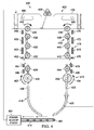
- Manufacturing environment 400 is an example of one implementation of manufacturing environment 300 in Figure 3 .
- additive manufacturing system 402 provides an example of one manner in which additive manufacturing system 308 in Figure 3 may be implemented.
- additive manufacturing system 402 may comprise chamber 404, curing system 406, precursor deposition system 408, movement system 410, separation system 412, recycling system 414, and temperature control system 416.
- chamber 404 may comprise walls 418 and door 420.
- Door 420 closes opening 422 in walls 418 of chamber 404.
- Curing system 406 may comprise laser system 424 in these examples.
- movement system 410 may include gears 426, 428, 430, 432, 434, 436, 438, 440, 442, and 444.
- gears 426, 428, 430, 432, and 434 may turn in the direction of arrow 445.
- Gears 436, 438, 440, 442, and 444 may turn in the direction of arrow 446.
- Separation system 412 may comprise cutter 448 and cutter 450.
- Cutter 448 may turn in the direction of arrow 452, while cutter 450 may turn in the direction of arrow 454.
- Temperature control system 416 may include elements 456, 458, 460, 462, 464, 466, 470, 472, 474, 476, 478, and 480. These elements may be selected from at least one of heating elements, cooling elements, and other suitable types of elements.
- recycling system 414 may comprise conveyor belt 482 and powder cleanup station 484. Powder cleanup station 484 may return any reusable precursor material to precursor deposition system 408.
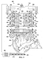
- object 500 may be manufactured through the placement of precursor material 502 in layers 504 onto base structure 506. Portions 508 of object 500 may be formed as layers 504 of precursor material 502 are placed onto base structure 506 with laser system 424 applying laser beam 510 to selectively cure precursor material 502.
- frame 501 may support object 500 as object 500 is formed.
- Frame 501 may comprise base structures 506, 514, 516, 518, 520, 522, and 524. As depicted, a cross-sectional view of frame 501 may be illustrated in this illustrative example. Further, base structures 514, 516, 518, 520, 522, and 524 may be seen in phantom view.
- portion 600 of frame 501 may be connected to portion 602 of object 500 in Figure 5 .
- base structure 506 may be connected to base structure 514 by connector 604 and connector 606. Further, base structure 514 may be connected to portion 602 of object 500 by connector 608 and connector 610. In this manner, portion 602 of object 500 may be supported by base structure 506 and base structure 514.
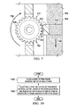
- FIG. 7 an illustration of a portion of a movement system engaging a base structure for a frame is depicted in accordance with an advantageous embodiment.
- gear 428 of movement system 410 may be seen engaging base structure 522 of frame 501.
- gear 428 may have teeth 702.
- Base structure 522 may have teeth 700.
- Gear 428 may be rotated in the direction of arrow 706, such that teeth 702 may engage teeth 700 on base structure 522. This rotation of gear 428 may cause base structure 522 and frame 501 to be moved along axis 708.
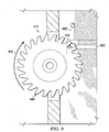
- movement system 800 may be used to engage frame 501 in Figure 5 in the place of movement system 410 in Figure 4 .
- movement system 800 may have track 802.
- Track 802 may have teeth 806 around track 802.
- Teeth 806 may be configured to engage teeth 808 on base structure 520, teeth 810 on base structure 518, and other teeth (not shown in this view) on other base structures (not shown in this view) for frame 501.
- track 802 may be moved such that teeth 806 move in the direction of arrow 804. This movement of track 802 and teeth 806 may cause frame 501 with base structure 518 and base structure 520 to be moved in a direction along axis 812.
- cutter 448 for separation system 412 may rotate in the direction of arrow 452 to separate base structure 514 from object 500 in Figure 5 .
- base structure 514 may be connected to connector 900 and connector 902.
- Connector 900 may have connected base structure 514 to base structure 516 in Figure 5 .
- Connector 902 may have connected base structure 514 to object 500 in Figure 5 .
- FIG. 10 an illustration of a flowchart of a process for manufacturing objects is depicted in accordance with an advantageous embodiment.
- the process may be implemented using additive manufacturing system 308 in manufacturing environment 300 in Figure 3 .
- the process may begin by placing layers 331 of precursor material 330 on top of each other (operation 1000).
- the process may selectively cure layers 331 of precursor material 330 as layers 331 of precursor material 330 are placed on top of each other to form object 324 and frame 326 associated with object 324 (operation 1002), with the process terminating thereafter.
- FIG. 11 an illustration of a flowchart of a process for manufacturing an object is depicted in accordance with an advantageous embodiment.
- the process illustrated in Figure 11 may be implemented using additive manufacturing system 308 in manufacturing environment 300 in Figure 3 .
- the process may begin by positioning base structure 332 for frame 326 with respect to movement system 316 (operation 1100). In operation 1100, the process may position base structure 332 such that movement system 316 may hold and/or move base structure 332 and frame 326 as frame 326 grows.
- layer 328 of precursor material 330 may be placed onto base structure 332 (operation 1102).
- layer 328 of precursor material 330 may be selectively cured using curing system 312 (operation 1104).
- Frame 326 with base structure 332 may be moved in a direction away from curing system 312 along axis 358 using movement system 316 (operation 1106).
- the layer of precursor material that has been selectively cured may be referred to as a prior layer in these examples.
- the process may place new layer 352 of precursor material 330 onto the prior layer of precursor material 330 (operation 1108).
- a determination may be made as to whether a new base structure is needed (operation 1110).
- new layer 352 of precursor material 330 may be selectively cured to form portion 356 of object 324 and portion 359 of new base structure 354 (operation 1112).
- the new layer may be selectively cured using curing system 312 to form another portion of object 324 and another portion of new base structure 354 (operation 1120). Thereafter, the process may return to operation 1114 as described above.
- new base structure 354 if new base structure 354 has been completed, a determination may be made as to whether object 324 has been completed (operation 1121). If object 324 has been completed, the process may then terminate. Otherwise, if object 324 has not been completed, the process may return to operation 1106 as described above. With reference again to operation 1110, if a new base structure is not needed, new layer 352 may be selectively cured by curing system 312 to form portion 356 of object 324 without forming portion 359 of new base structure 354 (operation 1122). Thereafter, the process may proceed to operation 1121 as described above.
- each block in the flowcharts or block diagrams may represent a module, segment, function, and/or a portion of an operation or step.
- the function or functions noted in the block may occur out of the order noted in the figures.
- two blocks shown in succession may be executed substantially concurrently, or the blocks may sometimes be executed in the reverse order, depending upon the functionality involved.
- other blocks may be added in addition to the illustrated blocks in a flowchart or block diagram.
- the different advantageous embodiments provide a method and apparatus for manufacturing objects.
- the different advantageous embodiments may place layers of precursor material on top of each other.
- the layers of precursor material may be selectively cured as they are placed on top of each other to form a portion of an object and a portion of a frame associated with the object.
Landscapes
- Engineering & Computer Science (AREA)
- Chemical & Material Sciences (AREA)
- Materials Engineering (AREA)
- Manufacturing & Machinery (AREA)
- Mechanical Engineering (AREA)
- Physics & Mathematics (AREA)
- Optics & Photonics (AREA)
- Life Sciences & Earth Sciences (AREA)
- Sustainable Development (AREA)
- Plasma & Fusion (AREA)
- Ceramic Engineering (AREA)
- Automation & Control Theory (AREA)
- Powder Metallurgy (AREA)
Applications Claiming Priority (2)
| Application Number | Priority Date | Filing Date | Title |
|---|---|---|---|
| US12/886,631 US9522501B2 (en) | 2010-09-21 | 2010-09-21 | Continuous linear production in a selective laser sintering system |
| PCT/US2011/046744 WO2012039843A1 (en) | 2010-09-21 | 2011-08-05 | Rapid manufacturing method and apparatus |
Publications (2)
| Publication Number | Publication Date |
|---|---|
| EP2618988A1 EP2618988A1 (en) | 2013-07-31 |
| EP2618988B1 true EP2618988B1 (en) | 2016-10-05 |
Family
ID=44515022
Family Applications (1)
| Application Number | Title | Priority Date | Filing Date |
|---|---|---|---|
| EP11749287.6A Active EP2618988B1 (en) | 2010-09-21 | 2011-08-05 | Rapid manufacturing method and apparatus |
Country Status (6)
| Country | Link |
|---|---|
| US (2) | US9522501B2 (enExample) |
| EP (1) | EP2618988B1 (enExample) |
| JP (1) | JP5801400B2 (enExample) |
| CN (2) | CN105922575B (enExample) |
| ES (1) | ES2610178T3 (enExample) |
| WO (1) | WO2012039843A1 (enExample) |
Families Citing this family (33)
| Publication number | Priority date | Publication date | Assignee | Title |
|---|---|---|---|---|
| DE202010005162U1 (de) * | 2010-04-17 | 2010-11-04 | Evonik Degussa Gmbh | Vorrichtung zur Verkleinerung des unteren Bauraums einer Lasersinteranlage |
| US9522501B2 (en) | 2010-09-21 | 2016-12-20 | The Boeing Company | Continuous linear production in a selective laser sintering system |
| US20130323473A1 (en) * | 2012-05-30 | 2013-12-05 | General Electric Company | Secondary structures for aircraft engines and processes therefor |
| US10029415B2 (en) | 2012-08-16 | 2018-07-24 | Stratasys, Inc. | Print head nozzle for use with additive manufacturing system |
| US9174388B2 (en) | 2012-08-16 | 2015-11-03 | Stratasys, Inc. | Draw control for extrusion-based additive manufacturing systems |
| US9168697B2 (en) | 2012-08-16 | 2015-10-27 | Stratasys, Inc. | Additive manufacturing system with extended printing volume, and methods of use thereof |
| US9636868B2 (en) | 2012-08-16 | 2017-05-02 | Stratasys, Inc. | Additive manufacturing system with extended printing volume, and methods of use thereof |
| US9511547B2 (en) | 2012-08-16 | 2016-12-06 | Stratasys, Inc. | Method for printing three-dimensional parts with additive manufacturing systems using scaffolds |
| US9327350B2 (en) | 2012-08-16 | 2016-05-03 | Stratasys, Inc. | Additive manufacturing technique for printing three-dimensional parts with printed receiving surfaces |
| US11020899B2 (en) | 2012-08-16 | 2021-06-01 | Stratasys, Inc. | Additive manufacturing system with extended printing volume, and methods of use thereof |
| US8961167B2 (en) | 2012-12-21 | 2015-02-24 | Stratasys, Inc. | Automated additive manufacturing system for printing three-dimensional parts, printing farm thereof, and method of use thereof |
| US9216544B2 (en) | 2012-12-21 | 2015-12-22 | Stratasys, Inc. | Automated additive manufacturing system for printing three-dimensional parts, printing farm thereof, and method of use thereof |
| US9421713B2 (en) | 2013-03-08 | 2016-08-23 | Stratasys, Inc. | Additive manufacturing method for printing three-dimensional parts with purge towers |
| US9399320B2 (en) | 2013-03-08 | 2016-07-26 | Stratasys, Inc. | Three-dimensional parts having interconnected hollow patterns, and method for generating and printing thereof |
| US10093039B2 (en) | 2013-03-08 | 2018-10-09 | Stratasys, Inc. | Three-dimensional parts having interconnected Hollow patterns, method of manufacturing and method of producing composite part |
| US9802360B2 (en) | 2013-06-04 | 2017-10-31 | Stratsys, Inc. | Platen planarizing process for additive manufacturing system |
| US9744730B2 (en) | 2013-11-22 | 2017-08-29 | Stratasys, Inc. | Magnetic platen assembly for additive manufacturing system |
| CA2859414C (en) | 2014-04-04 | 2017-03-14 | Matsuura Machinery Corporation | Metal powder processing equipment |
| US9452840B2 (en) * | 2014-04-15 | 2016-09-27 | The Boeing Company | Monolithic part and method of forming the monolithic part |
| JP6272723B2 (ja) * | 2014-04-21 | 2018-01-31 | 株式会社日立製作所 | ステンレス鋼、流体機器およびステンレス鋼の製造方法 |
| IL313945B2 (en) * | 2014-07-13 | 2025-07-01 | Stratasys Ltd | Method and system for controlled rotational 3D printing |
| GB2530495A (en) | 2014-09-23 | 2016-03-30 | Schlumberger Holdings | Solids in borehole fluids |
| GB201420601D0 (en) * | 2014-11-19 | 2015-01-07 | Digital Metal Ab | Method and apparatus for manufacturing a series of objects |
| US9694545B2 (en) | 2014-12-18 | 2017-07-04 | Stratasys, Inc. | Remotely-adjustable purge station for use in additive manufacturing systems |
| US9610733B2 (en) | 2015-01-06 | 2017-04-04 | Stratasys, Inc. | Additive manufacturing with soluble build sheet and part marking |
| US11691339B2 (en) | 2017-02-15 | 2023-07-04 | Hewlett-Packard Development Company, L.P. | Product framing |
| USD888115S1 (en) | 2017-03-16 | 2020-06-23 | Stratasys, Inc. | Nozzle |
| US10234848B2 (en) | 2017-05-24 | 2019-03-19 | Relativity Space, Inc. | Real-time adaptive control of additive manufacturing processes using machine learning |
| JP2021527582A (ja) | 2018-06-20 | 2021-10-14 | デジタル・アロイズ・インコーポレイテッド | 多径ワイヤフィーダ |
| US11247387B2 (en) | 2018-08-30 | 2022-02-15 | Stratasys, Inc. | Additive manufacturing system with platen having vacuum and air bearing |
| US11760031B1 (en) * | 2019-06-17 | 2023-09-19 | Valerie Nagel | Rapid manufacturing system and method |
| US20220281133A1 (en) * | 2019-08-23 | 2022-09-08 | Silfex, Inc. | 3d printing of fully dense and crack free silicon with selective laser melting/sintering at elevated temperatures |
| JP7449169B2 (ja) * | 2020-05-27 | 2024-03-13 | 株式会社東芝 | 造形物製造方法 |
Family Cites Families (21)
| Publication number | Priority date | Publication date | Assignee | Title |
|---|---|---|---|---|
| US4575330A (en) * | 1984-08-08 | 1986-03-11 | Uvp, Inc. | Apparatus for production of three-dimensional objects by stereolithography |
| US4863538A (en) | 1986-10-17 | 1989-09-05 | Board Of Regents, The University Of Texas System | Method and apparatus for producing parts by selective sintering |
| US4999143A (en) * | 1988-04-18 | 1991-03-12 | 3D Systems, Inc. | Methods and apparatus for production of three-dimensional objects by stereolithography |
| US5182056A (en) * | 1988-04-18 | 1993-01-26 | 3D Systems, Inc. | Stereolithography method and apparatus employing various penetration depths |
| US5137662A (en) * | 1988-11-08 | 1992-08-11 | 3-D Systems, Inc. | Method and apparatus for production of three-dimensional objects by stereolithography |
| US5248456A (en) * | 1989-06-12 | 1993-09-28 | 3D Systems, Inc. | Method and apparatus for cleaning stereolithographically produced objects |
| JP2957763B2 (ja) * | 1991-07-25 | 1999-10-06 | 松下電工株式会社 | 三次元形状の形成方法 |
| BE1008128A3 (nl) | 1994-03-10 | 1996-01-23 | Materialise Nv | Werkwijze voor het ondersteunen van een voorwerp vervaardigd door stereolithografie of een andere snelle prototypevervaardigingswerkwijze en voor het vervaardigen van de daarbij gebruikte steunkonstruktie. |
| ATE228927T1 (de) * | 1995-09-27 | 2002-12-15 | 3D Systems Inc | Verfahren und vorrichtung zur datenverarbeiten und zur system-steuerung in einem selectiven ablagerungsmodellsystem |
| JP3155185B2 (ja) * | 1995-12-20 | 2001-04-09 | 松下電工株式会社 | 三次元形状造形物の製造方法 |
| DE19948591A1 (de) * | 1999-10-08 | 2001-04-19 | Generis Gmbh | Rapid-Prototyping - Verfahren und - Vorrichtung |
| US6652256B2 (en) * | 2000-10-27 | 2003-11-25 | Dorsey D. Coe | Three-dimensional model colorization during model construction from computer aided design data |
| US6665574B2 (en) * | 2001-05-02 | 2003-12-16 | Northrop Grumman Corporation | Method of forming finished parts utilizing stereolithography technology |
| US7275925B2 (en) * | 2001-08-30 | 2007-10-02 | Micron Technology, Inc. | Apparatus for stereolithographic processing of components and assemblies |
| US7435072B2 (en) * | 2003-06-02 | 2008-10-14 | Hewlett-Packard Development Company, L.P. | Methods and systems for producing an object through solid freeform fabrication |
| GB0312909D0 (en) * | 2003-06-05 | 2003-07-09 | Univ Liverpool | Apparatus for manufacturing three dimensional items |
| US20070164485A1 (en) * | 2003-10-27 | 2007-07-19 | Sheng-Jye Hwang | Method for forming objects |
| DE102005015870B3 (de) * | 2005-04-06 | 2006-10-26 | Eos Gmbh Electro Optical Systems | Vorrichtung und Verfahren zum Herstellen eines dreidimensionalen Objekts |
| US20070075461A1 (en) * | 2005-09-30 | 2007-04-05 | 3D Systems, Inc. | Rapid prototyping and manufacturing system and method |
| US8046097B2 (en) | 2007-09-17 | 2011-10-25 | 3D Systems, Inc. | Region-based supports for parts produced by solid freeform fabrication |
| US9522501B2 (en) | 2010-09-21 | 2016-12-20 | The Boeing Company | Continuous linear production in a selective laser sintering system |
-
2010
- 2010-09-21 US US12/886,631 patent/US9522501B2/en active Active
-
2011
- 2011-08-05 ES ES11749287.6T patent/ES2610178T3/es active Active
- 2011-08-05 JP JP2013529153A patent/JP5801400B2/ja active Active
- 2011-08-05 CN CN201610225562.5A patent/CN105922575B/zh active Active
- 2011-08-05 CN CN201180045403.2A patent/CN103118859B/zh active Active
- 2011-08-05 EP EP11749287.6A patent/EP2618988B1/en active Active
- 2011-08-05 WO PCT/US2011/046744 patent/WO2012039843A1/en not_active Ceased
-
2016
- 2016-12-04 US US15/368,665 patent/US9937557B2/en active Active
Also Published As
| Publication number | Publication date |
|---|---|
| US9937557B2 (en) | 2018-04-10 |
| JP2013542867A (ja) | 2013-11-28 |
| CN105922575A (zh) | 2016-09-07 |
| US9522501B2 (en) | 2016-12-20 |
| US20170136544A1 (en) | 2017-05-18 |
| CN103118859A (zh) | 2013-05-22 |
| JP5801400B2 (ja) | 2015-10-28 |
| ES2610178T3 (es) | 2017-04-26 |
| WO2012039843A1 (en) | 2012-03-29 |
| EP2618988A1 (en) | 2013-07-31 |
| CN105922575B (zh) | 2018-06-22 |
| CN103118859B (zh) | 2016-03-23 |
| US20120067501A1 (en) | 2012-03-22 |
Similar Documents
| Publication | Publication Date | Title |
|---|---|---|
| EP2618988B1 (en) | Rapid manufacturing method and apparatus | |
| US11642851B2 (en) | Multiple axis robotic additive manufacturing system and methods | |
| US8206637B2 (en) | Geometry adaptive laser sintering system | |
| EP3580041B1 (en) | Apparatus and method for printing long composite thermoplastic parts on a dual gantry machine during additive manufacturing | |
| EP3196000B1 (en) | Multi-planar fiber matrix tool-less preform for resin infusion | |
| US9943992B2 (en) | Controlling temperature in exothermic reactions with a phase change material | |
| JP6755638B2 (ja) | 一体型取付部品を有する複合材部品を製造する方法 | |
| TW201936369A (zh) | 使用積層製造以形成部件之系統,裝置及方法 | |
| Tofan-Negru et al. | Analysis and characterization of additive manufacturing processes | |
| KR100362738B1 (ko) | 초음파 장치를 이용한 용착 적층식 쾌속조형방법 및쾌속조형장치 | |
| CN112388973B (zh) | 用于增材制造的等离子体处理粉末 |
Legal Events
| Date | Code | Title | Description |
|---|---|---|---|
| PUAI | Public reference made under article 153(3) epc to a published international application that has entered the european phase |
Free format text: ORIGINAL CODE: 0009012 |
|
| 17P | Request for examination filed |
Effective date: 20130422 |
|
| AK | Designated contracting states |
Kind code of ref document: A1 Designated state(s): AL AT BE BG CH CY CZ DE DK EE ES FI FR GB GR HR HU IE IS IT LI LT LU LV MC MK MT NL NO PL PT RO RS SE SI SK SM TR |
|
| DAX | Request for extension of the european patent (deleted) | ||
| 17Q | First examination report despatched |
Effective date: 20150609 |
|
| GRAP | Despatch of communication of intention to grant a patent |
Free format text: ORIGINAL CODE: EPIDOSNIGR1 |
|
| INTG | Intention to grant announced |
Effective date: 20160504 |
|
| GRAS | Grant fee paid |
Free format text: ORIGINAL CODE: EPIDOSNIGR3 |
|
| GRAA | (expected) grant |
Free format text: ORIGINAL CODE: 0009210 |
|
| AK | Designated contracting states |
Kind code of ref document: B1 Designated state(s): AL AT BE BG CH CY CZ DE DK EE ES FI FR GB GR HR HU IE IS IT LI LT LU LV MC MK MT NL NO PL PT RO RS SE SI SK SM TR |
|
| REG | Reference to a national code |
Ref country code: GB Ref legal event code: FG4D |
|
| REG | Reference to a national code |
Ref country code: CH Ref legal event code: EP |
|
| REG | Reference to a national code |
Ref country code: AT Ref legal event code: REF Ref document number: 834237 Country of ref document: AT Kind code of ref document: T Effective date: 20161015 |
|
| REG | Reference to a national code |
Ref country code: IE Ref legal event code: FG4D |
|
| REG | Reference to a national code |
Ref country code: DE Ref legal event code: R096 Ref document number: 602011030992 Country of ref document: DE |
|
| REG | Reference to a national code |
Ref country code: DE Ref legal event code: R079 Ref document number: 602011030992 Country of ref document: DE Free format text: PREVIOUS MAIN CLASS: B29C0067000000 Ipc: B29C0064106000 |
|
| REG | Reference to a national code |
Ref country code: NL Ref legal event code: MP Effective date: 20161005 |
|
| REG | Reference to a national code |
Ref country code: LT Ref legal event code: MG4D |
|
| PG25 | Lapsed in a contracting state [announced via postgrant information from national office to epo] |
Ref country code: LV Free format text: LAPSE BECAUSE OF FAILURE TO SUBMIT A TRANSLATION OF THE DESCRIPTION OR TO PAY THE FEE WITHIN THE PRESCRIBED TIME-LIMIT Effective date: 20161005 |
|
| REG | Reference to a national code |
Ref country code: AT Ref legal event code: MK05 Ref document number: 834237 Country of ref document: AT Kind code of ref document: T Effective date: 20161005 |
|
| REG | Reference to a national code |
Ref country code: ES Ref legal event code: FG2A Ref document number: 2610178 Country of ref document: ES Kind code of ref document: T3 Effective date: 20170426 |
|
| PG25 | Lapsed in a contracting state [announced via postgrant information from national office to epo] |
Ref country code: SE Free format text: LAPSE BECAUSE OF FAILURE TO SUBMIT A TRANSLATION OF THE DESCRIPTION OR TO PAY THE FEE WITHIN THE PRESCRIBED TIME-LIMIT Effective date: 20161005 Ref country code: LT Free format text: LAPSE BECAUSE OF FAILURE TO SUBMIT A TRANSLATION OF THE DESCRIPTION OR TO PAY THE FEE WITHIN THE PRESCRIBED TIME-LIMIT Effective date: 20161005 Ref country code: NO Free format text: LAPSE BECAUSE OF FAILURE TO SUBMIT A TRANSLATION OF THE DESCRIPTION OR TO PAY THE FEE WITHIN THE PRESCRIBED TIME-LIMIT Effective date: 20170105 Ref country code: GR Free format text: LAPSE BECAUSE OF FAILURE TO SUBMIT A TRANSLATION OF THE DESCRIPTION OR TO PAY THE FEE WITHIN THE PRESCRIBED TIME-LIMIT Effective date: 20170106 |
|
| PG25 | Lapsed in a contracting state [announced via postgrant information from national office to epo] |
Ref country code: RS Free format text: LAPSE BECAUSE OF FAILURE TO SUBMIT A TRANSLATION OF THE DESCRIPTION OR TO PAY THE FEE WITHIN THE PRESCRIBED TIME-LIMIT Effective date: 20161005 Ref country code: IS Free format text: LAPSE BECAUSE OF FAILURE TO SUBMIT A TRANSLATION OF THE DESCRIPTION OR TO PAY THE FEE WITHIN THE PRESCRIBED TIME-LIMIT Effective date: 20170205 Ref country code: NL Free format text: LAPSE BECAUSE OF FAILURE TO SUBMIT A TRANSLATION OF THE DESCRIPTION OR TO PAY THE FEE WITHIN THE PRESCRIBED TIME-LIMIT Effective date: 20161005 Ref country code: FI Free format text: LAPSE BECAUSE OF FAILURE TO SUBMIT A TRANSLATION OF THE DESCRIPTION OR TO PAY THE FEE WITHIN THE PRESCRIBED TIME-LIMIT Effective date: 20161005 Ref country code: AT Free format text: LAPSE BECAUSE OF FAILURE TO SUBMIT A TRANSLATION OF THE DESCRIPTION OR TO PAY THE FEE WITHIN THE PRESCRIBED TIME-LIMIT Effective date: 20161005 Ref country code: HR Free format text: LAPSE BECAUSE OF FAILURE TO SUBMIT A TRANSLATION OF THE DESCRIPTION OR TO PAY THE FEE WITHIN THE PRESCRIBED TIME-LIMIT Effective date: 20161005 Ref country code: BE Free format text: LAPSE BECAUSE OF FAILURE TO SUBMIT A TRANSLATION OF THE DESCRIPTION OR TO PAY THE FEE WITHIN THE PRESCRIBED TIME-LIMIT Effective date: 20161005 Ref country code: PL Free format text: LAPSE BECAUSE OF FAILURE TO SUBMIT A TRANSLATION OF THE DESCRIPTION OR TO PAY THE FEE WITHIN THE PRESCRIBED TIME-LIMIT Effective date: 20161005 Ref country code: PT Free format text: LAPSE BECAUSE OF FAILURE TO SUBMIT A TRANSLATION OF THE DESCRIPTION OR TO PAY THE FEE WITHIN THE PRESCRIBED TIME-LIMIT Effective date: 20170206 |
|
| REG | Reference to a national code |
Ref country code: DE Ref legal event code: R097 Ref document number: 602011030992 Country of ref document: DE |
|
| PG25 | Lapsed in a contracting state [announced via postgrant information from national office to epo] |
Ref country code: CZ Free format text: LAPSE BECAUSE OF FAILURE TO SUBMIT A TRANSLATION OF THE DESCRIPTION OR TO PAY THE FEE WITHIN THE PRESCRIBED TIME-LIMIT Effective date: 20161005 Ref country code: SK Free format text: LAPSE BECAUSE OF FAILURE TO SUBMIT A TRANSLATION OF THE DESCRIPTION OR TO PAY THE FEE WITHIN THE PRESCRIBED TIME-LIMIT Effective date: 20161005 Ref country code: RO Free format text: LAPSE BECAUSE OF FAILURE TO SUBMIT A TRANSLATION OF THE DESCRIPTION OR TO PAY THE FEE WITHIN THE PRESCRIBED TIME-LIMIT Effective date: 20161005 Ref country code: EE Free format text: LAPSE BECAUSE OF FAILURE TO SUBMIT A TRANSLATION OF THE DESCRIPTION OR TO PAY THE FEE WITHIN THE PRESCRIBED TIME-LIMIT Effective date: 20161005 Ref country code: DK Free format text: LAPSE BECAUSE OF FAILURE TO SUBMIT A TRANSLATION OF THE DESCRIPTION OR TO PAY THE FEE WITHIN THE PRESCRIBED TIME-LIMIT Effective date: 20161005 |
|
| PLBE | No opposition filed within time limit |
Free format text: ORIGINAL CODE: 0009261 |
|
| STAA | Information on the status of an ep patent application or granted ep patent |
Free format text: STATUS: NO OPPOSITION FILED WITHIN TIME LIMIT |
|
| REG | Reference to a national code |
Ref country code: FR Ref legal event code: PLFP Year of fee payment: 7 |
|
| PG25 | Lapsed in a contracting state [announced via postgrant information from national office to epo] |
Ref country code: SM Free format text: LAPSE BECAUSE OF FAILURE TO SUBMIT A TRANSLATION OF THE DESCRIPTION OR TO PAY THE FEE WITHIN THE PRESCRIBED TIME-LIMIT Effective date: 20161005 Ref country code: BG Free format text: LAPSE BECAUSE OF FAILURE TO SUBMIT A TRANSLATION OF THE DESCRIPTION OR TO PAY THE FEE WITHIN THE PRESCRIBED TIME-LIMIT Effective date: 20170105 |
|
| 26N | No opposition filed |
Effective date: 20170706 |
|
| PG25 | Lapsed in a contracting state [announced via postgrant information from national office to epo] |
Ref country code: SI Free format text: LAPSE BECAUSE OF FAILURE TO SUBMIT A TRANSLATION OF THE DESCRIPTION OR TO PAY THE FEE WITHIN THE PRESCRIBED TIME-LIMIT Effective date: 20161005 |
|
| REG | Reference to a national code |
Ref country code: CH Ref legal event code: PL |
|
| PG25 | Lapsed in a contracting state [announced via postgrant information from national office to epo] |
Ref country code: MC Free format text: LAPSE BECAUSE OF FAILURE TO SUBMIT A TRANSLATION OF THE DESCRIPTION OR TO PAY THE FEE WITHIN THE PRESCRIBED TIME-LIMIT Effective date: 20161005 |
|
| PG25 | Lapsed in a contracting state [announced via postgrant information from national office to epo] |
Ref country code: LI Free format text: LAPSE BECAUSE OF NON-PAYMENT OF DUE FEES Effective date: 20170831 Ref country code: CH Free format text: LAPSE BECAUSE OF NON-PAYMENT OF DUE FEES Effective date: 20170831 |
|
| REG | Reference to a national code |
Ref country code: IE Ref legal event code: MM4A |
|
| PG25 | Lapsed in a contracting state [announced via postgrant information from national office to epo] |
Ref country code: LU Free format text: LAPSE BECAUSE OF NON-PAYMENT OF DUE FEES Effective date: 20170805 |
|
| PG25 | Lapsed in a contracting state [announced via postgrant information from national office to epo] |
Ref country code: IE Free format text: LAPSE BECAUSE OF NON-PAYMENT OF DUE FEES Effective date: 20170805 |
|
| REG | Reference to a national code |
Ref country code: FR Ref legal event code: PLFP Year of fee payment: 8 |
|
| PG25 | Lapsed in a contracting state [announced via postgrant information from national office to epo] |
Ref country code: MT Free format text: LAPSE BECAUSE OF NON-PAYMENT OF DUE FEES Effective date: 20170805 |
|
| PG25 | Lapsed in a contracting state [announced via postgrant information from national office to epo] |
Ref country code: HU Free format text: LAPSE BECAUSE OF FAILURE TO SUBMIT A TRANSLATION OF THE DESCRIPTION OR TO PAY THE FEE WITHIN THE PRESCRIBED TIME-LIMIT; INVALID AB INITIO Effective date: 20110805 |
|
| PG25 | Lapsed in a contracting state [announced via postgrant information from national office to epo] |
Ref country code: CY Free format text: LAPSE BECAUSE OF NON-PAYMENT OF DUE FEES Effective date: 20161005 |
|
| PG25 | Lapsed in a contracting state [announced via postgrant information from national office to epo] |
Ref country code: MK Free format text: LAPSE BECAUSE OF FAILURE TO SUBMIT A TRANSLATION OF THE DESCRIPTION OR TO PAY THE FEE WITHIN THE PRESCRIBED TIME-LIMIT Effective date: 20161005 |
|
| PG25 | Lapsed in a contracting state [announced via postgrant information from national office to epo] |
Ref country code: TR Free format text: LAPSE BECAUSE OF FAILURE TO SUBMIT A TRANSLATION OF THE DESCRIPTION OR TO PAY THE FEE WITHIN THE PRESCRIBED TIME-LIMIT Effective date: 20161005 |
|
| PG25 | Lapsed in a contracting state [announced via postgrant information from national office to epo] |
Ref country code: AL Free format text: LAPSE BECAUSE OF FAILURE TO SUBMIT A TRANSLATION OF THE DESCRIPTION OR TO PAY THE FEE WITHIN THE PRESCRIBED TIME-LIMIT Effective date: 20161005 |
|
| REG | Reference to a national code |
Ref country code: DE Ref legal event code: R082 Ref document number: 602011030992 Country of ref document: DE Representative=s name: KILBURN & STRODE LLP, NL |
|
| P01 | Opt-out of the competence of the unified patent court (upc) registered |
Effective date: 20230516 |
|
| PGFP | Annual fee paid to national office [announced via postgrant information from national office to epo] |
Ref country code: ES Payment date: 20250901 Year of fee payment: 15 |
|
| PGFP | Annual fee paid to national office [announced via postgrant information from national office to epo] |
Ref country code: DE Payment date: 20250827 Year of fee payment: 15 |
|
| PGFP | Annual fee paid to national office [announced via postgrant information from national office to epo] |
Ref country code: IT Payment date: 20250820 Year of fee payment: 15 |
|
| PGFP | Annual fee paid to national office [announced via postgrant information from national office to epo] |
Ref country code: GB Payment date: 20250827 Year of fee payment: 15 |
|
| PGFP | Annual fee paid to national office [announced via postgrant information from national office to epo] |
Ref country code: FR Payment date: 20250825 Year of fee payment: 15 |