EP2618749B1 - Chirurgische clipanordnung - Google Patents
Chirurgische clipanordnung Download PDFInfo
- Publication number
- EP2618749B1 EP2618749B1 EP11758463.1A EP11758463A EP2618749B1 EP 2618749 B1 EP2618749 B1 EP 2618749B1 EP 11758463 A EP11758463 A EP 11758463A EP 2618749 B1 EP2618749 B1 EP 2618749B1
- Authority
- EP
- European Patent Office
- Prior art keywords
- clip
- parts
- accordance
- applicator
- surgical
- Prior art date
- Legal status (The legal status is an assumption and is not a legal conclusion. Google has not performed a legal analysis and makes no representation as to the accuracy of the status listed.)
- Not-in-force
Links
- 230000015271 coagulation Effects 0.000 claims description 14
- 238000005345 coagulation Methods 0.000 claims description 14
- 238000002955 isolation Methods 0.000 claims 1
- 238000000034 method Methods 0.000 description 9
- 229920003023 plastic Polymers 0.000 description 6
- 239000004033 plastic Substances 0.000 description 6
- 239000000463 material Substances 0.000 description 5
- 238000007789 sealing Methods 0.000 description 5
- 239000002184 metal Substances 0.000 description 2
- 230000000712 assembly Effects 0.000 description 1
- 238000000429 assembly Methods 0.000 description 1
- 239000008280 blood Substances 0.000 description 1
- 210000004369 blood Anatomy 0.000 description 1
- 150000001875 compounds Chemical class 0.000 description 1
- 230000000694 effects Effects 0.000 description 1
- 239000012777 electrically insulating material Substances 0.000 description 1
Images



Classifications
-
- A—HUMAN NECESSITIES
- A61—MEDICAL OR VETERINARY SCIENCE; HYGIENE
- A61B—DIAGNOSIS; SURGERY; IDENTIFICATION
- A61B17/00—Surgical instruments, devices or methods
- A61B17/12—Surgical instruments, devices or methods for ligaturing or otherwise compressing tubular parts of the body, e.g. blood vessels or umbilical cord
- A61B17/122—Clamps or clips, e.g. for the umbilical cord
-
- A—HUMAN NECESSITIES
- A61—MEDICAL OR VETERINARY SCIENCE; HYGIENE
- A61B—DIAGNOSIS; SURGERY; IDENTIFICATION
- A61B17/00—Surgical instruments, devices or methods
- A61B17/12—Surgical instruments, devices or methods for ligaturing or otherwise compressing tubular parts of the body, e.g. blood vessels or umbilical cord
- A61B17/128—Surgical instruments, devices or methods for ligaturing or otherwise compressing tubular parts of the body, e.g. blood vessels or umbilical cord for applying or removing clamps or clips
-
- A—HUMAN NECESSITIES
- A61—MEDICAL OR VETERINARY SCIENCE; HYGIENE
- A61B—DIAGNOSIS; SURGERY; IDENTIFICATION
- A61B17/00—Surgical instruments, devices or methods
- A61B17/12—Surgical instruments, devices or methods for ligaturing or otherwise compressing tubular parts of the body, e.g. blood vessels or umbilical cord
- A61B17/128—Surgical instruments, devices or methods for ligaturing or otherwise compressing tubular parts of the body, e.g. blood vessels or umbilical cord for applying or removing clamps or clips
- A61B17/1285—Surgical instruments, devices or methods for ligaturing or otherwise compressing tubular parts of the body, e.g. blood vessels or umbilical cord for applying or removing clamps or clips for minimally invasive surgery
-
- A—HUMAN NECESSITIES
- A61—MEDICAL OR VETERINARY SCIENCE; HYGIENE
- A61B—DIAGNOSIS; SURGERY; IDENTIFICATION
- A61B18/00—Surgical instruments, devices or methods for transferring non-mechanical forms of energy to or from the body
- A61B18/04—Surgical instruments, devices or methods for transferring non-mechanical forms of energy to or from the body by heating
- A61B18/12—Surgical instruments, devices or methods for transferring non-mechanical forms of energy to or from the body by heating by passing a current through the tissue to be heated, e.g. high-frequency current
- A61B18/14—Probes or electrodes therefor
- A61B18/1442—Probes having pivoting end effectors, e.g. forceps
- A61B18/1445—Probes having pivoting end effectors, e.g. forceps at the distal end of a shaft, e.g. forceps or scissors at the end of a rigid rod
- A61B18/1447—Probes having pivoting end effectors, e.g. forceps at the distal end of a shaft, e.g. forceps or scissors at the end of a rigid rod wherein sliding surfaces cause opening/closing of the end effectors
-
- A—HUMAN NECESSITIES
- A61—MEDICAL OR VETERINARY SCIENCE; HYGIENE
- A61B—DIAGNOSIS; SURGERY; IDENTIFICATION
- A61B17/00—Surgical instruments, devices or methods
- A61B17/064—Surgical staples, i.e. penetrating the tissue
-
- A—HUMAN NECESSITIES
- A61—MEDICAL OR VETERINARY SCIENCE; HYGIENE
- A61B—DIAGNOSIS; SURGERY; IDENTIFICATION
- A61B18/00—Surgical instruments, devices or methods for transferring non-mechanical forms of energy to or from the body
- A61B18/04—Surgical instruments, devices or methods for transferring non-mechanical forms of energy to or from the body by heating
- A61B18/12—Surgical instruments, devices or methods for transferring non-mechanical forms of energy to or from the body by heating by passing a current through the tissue to be heated, e.g. high-frequency current
- A61B18/14—Probes or electrodes therefor
-
- A—HUMAN NECESSITIES
- A61—MEDICAL OR VETERINARY SCIENCE; HYGIENE
- A61B—DIAGNOSIS; SURGERY; IDENTIFICATION
- A61B17/00—Surgical instruments, devices or methods
- A61B2017/00477—Coupling
-
- A—HUMAN NECESSITIES
- A61—MEDICAL OR VETERINARY SCIENCE; HYGIENE
- A61B—DIAGNOSIS; SURGERY; IDENTIFICATION
- A61B17/00—Surgical instruments, devices or methods
- A61B2017/00831—Material properties
- A61B2017/00929—Material properties isolating electrical current
-
- A—HUMAN NECESSITIES
- A61—MEDICAL OR VETERINARY SCIENCE; HYGIENE
- A61B—DIAGNOSIS; SURGERY; IDENTIFICATION
- A61B18/00—Surgical instruments, devices or methods for transferring non-mechanical forms of energy to or from the body
- A61B18/04—Surgical instruments, devices or methods for transferring non-mechanical forms of energy to or from the body by heating
- A61B18/12—Surgical instruments, devices or methods for transferring non-mechanical forms of energy to or from the body by heating by passing a current through the tissue to be heated, e.g. high-frequency current
- A61B18/14—Probes or electrodes therefor
- A61B18/1442—Probes having pivoting end effectors, e.g. forceps
- A61B2018/145—Probes having pivoting end effectors, e.g. forceps wherein the effectors remain parallel during closing and opening
-
- Y—GENERAL TAGGING OF NEW TECHNOLOGICAL DEVELOPMENTS; GENERAL TAGGING OF CROSS-SECTIONAL TECHNOLOGIES SPANNING OVER SEVERAL SECTIONS OF THE IPC; TECHNICAL SUBJECTS COVERED BY FORMER USPC CROSS-REFERENCE ART COLLECTIONS [XRACs] AND DIGESTS
- Y10—TECHNICAL SUBJECTS COVERED BY FORMER USPC
- Y10S—TECHNICAL SUBJECTS COVERED BY FORMER USPC CROSS-REFERENCE ART COLLECTIONS [XRACs] AND DIGESTS
- Y10S227/00—Elongated-member-driving apparatus
- Y10S227/902—Surgical clips or staples
Definitions
- the invention relates to a surgical clip assembly, in particular for closing vessels in neurosurgery.
- U-shaped or V-shaped metal clips are used extensively, which are placed on the vessel with a clip applying forceps and deformed by the closing force of the forceps closing the affected vessel.
- Such clips are for example from the DE 195 20 158 C2 known.
- the object of the invention is to propose a surgical clip assembly with which the closing of vessels, especially in neurosurgery, succeeds even more reliably.
- the surgical clip assembly according to the invention therefore does not rely only on a mechanical closure of the vessel, in which the two typically Metallic clip parts in the form of clamping arms hold the vessel compressed in its cross-section and thus close, but due to the electrically isolated clip parts or clamping arms can simultaneously initiate a coagulation or sealing process in the clip area when creating the surgical clip assembly, so that in addition to the mechanical closure even a cohesive closure of the vessel is achieved.
- a stiffening of the tissue takes place in the coagulation region as a result of the coagulation and sealing process, so that the clip arrangement additionally finds a secure hold.
- a clip applicator according to the invention is preferably used which will be described in more detail below.
- the surgical clip assembly with its two electrically insulated from each other electrically conductive clip parts, in particular clamping arms, can be realized in various embodiments.
- the clip parts are part of a U- or V-shaped clip configuration, wherein the two clip parts are held at a first end to an electrically insulating holding part and thereby form the two legs of the U- or V-shaped configuration.
- the electrically insulating holding part is plastically deformable.
- Plastics are typical materials for the insulating holding parts.
- the two clip parts are symmetrical to each other, wherein the electrically insulating holding part is kept as small as possible in order to provide the largest possible range of effect for coagulation on the electrically conductive clip parts.
- the two clip parts are formed substantially identical and arranged mirror-inverted with its first end to the electrically insulating holding part.
- the electrically insulating holding part can be arranged asymmetrically on the U- or V-shaped clip, so that a first clip part or clamping arm comprises one leg and the middle bow part, while the electrically insulating holding part and the second clip part or clamping arm form the other leg.
- the plastic deformation is not necessarily held on the holding part, but primarily on the middle arch portion of a clip part, which typically consists of metal.
- the clip parts or clamping arms can be connected to one another at their respective free end opposite the first end with an electrically insulating connection.
- the compound is preferably formed as a latching connection.
- electrically insulating locking elements are arranged, which lock together during mechanical closing of the clip and thus already provide an additional mechanical fixation of the clip to the vessel to be closed.
- the electrically insulating connection can also be made for the electrically insulating connection to be a cohesive connection forming at the free ends of the clip parts in the course of the heat development during the coagulation and sealing process.
- two clip parts which are each formed substantially U- or V-shaped, are held parallel to each other aligned at a predetermined distance.
- These two clip parts will be for application to a vessel detected by a clip applicator, which has a gripping tool for the two clip parts with mutually electrically isolated gripping jaws.
- the two clip parts can then be applied to the vessel with the clip applicator, and in the same step, a sealing process in the region of the mechanical closure of the vessel can be achieved via a coagulation flow. This results in the coagulation process an additional cohesive closure of the vessel.
- the two clip parts can be kept in a magazine, for example, in a desired arrangement until they are picked up by the gripping tool.
- the electrically isolated gripping jaws hold the two clip parts after they have been removed from the magazine until the application electrically isolated at a distance from each other.
- the two clip parts are connected by means of an electrically insulating holder aligned parallel to each other at the predetermined distance.
- the holder may in turn be made of a plastic. Again, the design of the jaws of the clip applicator is easier.
- the holder may be in one piece and, for example, connect the two clip parts together in their respective center.
- the free ends of the two clip parts are each connected to each other with an electrically insulating holding part of the holder.
- these two holding parts of the holder can then also be designed as latching elements, which engage with one another when the clip is applied to the vessel.
- latching elements can also be provided to use electrically insulating holding parts, which enter into a cohesive connection with each other during the heat development during the coagulation and the sealing process of the vessel.
- the invention further relates to a clip applicator for use with a surgical clip assembly according to the invention as described above.
- the applicator according to the invention has a gripping tool with two gripping jaws for the two clip parts which are electrically insulated from one another, wherein the gripping jaws can be connected to a current source supplying a coagulation current.
- the applicator comprises a magazine with a clip carrier, wherein a plurality of surgical clip arrangements are arranged on the clip carrier as described above.
- the current source with which the gripping jaws of the applicator can be connected is preferably a high-frequency current source.
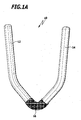
- FIG. 1A shows a surgical clip assembly 10 (hereinafter also referred to as clip) with two electrically conductive clip parts or clamps in the form of legs 12 and 14, in a substantially U-shaped arrangement electrically isolated from each other via a holding part 16 at a predetermined distance from each other and are held opposite each other.
- clip a surgical clip assembly 10
- the holding part is made of a plastically deformable plastic, so that when applying the clip 10 results in a permanent mechanical closure of the vessel.
- a coagulation stream is then applied via a gripper tool of an applicator, so that in addition to the mechanical closure of the vessel additionally takes place a seal.
- FIG. 1B illustrated clip assembly 20 has unbalanced clamping arms in the form of the legs 22, 24 and a corresponding eccentrically arranged electrically insulating holding part 26.
- a curved part 28 integrally formed on the leg 22 is primarily plastically deformed and thus ensures a permanent mechanical closure of the vessel.
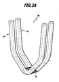
- FIG. 2A a surgical clip assembly 30 is shown in which two each substantially U-shaped clip parts or clamping arms 32, 34 are arranged parallel to each other. These two clip parts can be connected to one another via a web 36 made of an electrically insulating material, for example plastic, for example, in their central region and kept at a distance.
- a web 36 made of an electrically insulating material, for example plastic, for example, in their central region and kept at a distance.
- FIG. 2B further preferred is a clip assembly 40 of FIG. 2B in which two U-shaped clip parts or clamping arms 42, 44 at their respective free ends 52, 53; 54.55 via two holding parts 46, 48 are kept electrically isolated at a distance, wherein the holding part 46 is preferably equipped with a latching element 50, the in FIG. 2B is hook-shaped, and with the holding part 48 is positively connected.
- the material of the holding parts 46, 48 or in particular also of the latching part 50 is selected such that the heat developing during the coagulation of the vessel material is sufficient to produce a material connection between the holding parts 46, 48, especially between the part 50 and the part 48, to lead.
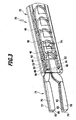
- FIG. 3 shows a clip applicator 70 according to the invention, in which, for the sake of simplicity, the area of the handle for actuating the applicator 70 is omitted.
- FIG. 3 Shown is in FIG. 3 a shaft 72 of the applicator 70, in which a clip magazine 74 is arranged with a series of clips 40 arranged one behind the other.
- a gripping tool 71 with two electrically isolated from each other gripping jaws 76, 77 and 78, 79, which in an application of a clip 40 whose clip parts 42, 44 with the free Ends 52, 53; 54, 55 in receiving grooves 80, 81; 82, 83 record and lead.
- FIG. 2B The sequence of steps in the application of a clip assembly according to the invention using the example of the clip assembly 40 of the invention FIG. 2B is in the FIGS. 4A to D shown schematically. Analogously, the process with clips of the Figures 1A . 1B and 2A represents.
- FIG. 4A shows the clip 40 in a sectional view with its legs 52, 54 below and the legs 53, 55 above a vessel 100.
- the legs 52, 54 are guided and held in grooves 82, 83 of the jaws 78, 79, and the legs 53, 55 are guided and held in the grooves 80, 81 of the jaws 76, 77.
- the jaws 76, 77 and 78, 79 moves against each other while the legs 52, 54 and 53, 55 approached each other while the vessel 100 in the longitudinal direction of the vessel spaced areas 102 and 104 mechanically closed.
- the part 50 engages the holding part 48 and thus secures the closed position of the clip 40.
- the gripping jaws 76, 78 and 77, 79 are connected in pairs to one pole of an HF power source, so that then a coagulated region 106 of the vessel 100 forms between the mechanically sealed regions 102, 104 of the vessel 100 (cf. FIG. 4C ).
Landscapes
- Health & Medical Sciences (AREA)
- Surgery (AREA)
- Life Sciences & Earth Sciences (AREA)
- Engineering & Computer Science (AREA)
- Heart & Thoracic Surgery (AREA)
- Veterinary Medicine (AREA)
- Nuclear Medicine, Radiotherapy & Molecular Imaging (AREA)
- Biomedical Technology (AREA)
- Public Health (AREA)
- Medical Informatics (AREA)
- Molecular Biology (AREA)
- Animal Behavior & Ethology (AREA)
- General Health & Medical Sciences (AREA)
- Reproductive Health (AREA)
- Vascular Medicine (AREA)
- Physics & Mathematics (AREA)
- Plasma & Fusion (AREA)
- Otolaryngology (AREA)
- Surgical Instruments (AREA)
Description
- Die Erfindung betrifft eine chirurgische Clipanordnung, insbesondere zum Verschließen von Gefäßen in der Neurochirurgie.
- Zu diesem Zweck kommen in großem Umfang U- oder V-förmige metallische Clips zum Einsatz, die mit einer Clipanlegezange an dem Gefäß platziert und über die Schließkraft der Zange verformt das betroffene Gefäß verschließen. Solche Clips sind beispielsweise aus der
DE 195 20 158 C2 bekannt. - Aus der
US 2006/0217749 A1 ist ein Magazin mit chirurgischen Clips aus einem Kunststoffmaterial bekannt, in dem die aus Kunststoff gefertigten Clips in paralleler Ausrichtung zueinander gehalten sind. - Um den Verschluss eines Gefäßes durch einen Clip sicherer zu machen, wurden schon so genannte Doppelstegclips vorgeschlagen (vgl. z.B.
DE 10 2006 001 344 A1 ), bei denen zwei einstückig miteinander ausgebildete, im Wesentlichen parallel zu einander angeordnete, U- oder V-förmige Bügel des Clips zwei in Längsrichtung des Gefäßes hintereinander liegende Verschlussstellen an dem Gefäß bilden. - Trotzdem kann es in kritischen Situationen noch vorkommen, dass auch ein solcher doppelter Verschluss des Gefäßes kleine Leckagen nicht verhindert, so dass immer noch kleinere Blutmengen austreten können.
- Aufgabe der Erfindung ist es, eine chirurgische Clipanordnung vorzuschlagen, mit der das Verschließen von Gefäßen insbesondere in der Neurochirurgie noch sicherer gelingt.
- Diese Aufgabe wird von einer chirurgischen Clipanordnung wie in Anspruch 1 definiert gelöst.
- Die erfindungsgemäße chirurgische Clipanordnung setzt demnach nicht nur auf einen mechanischen Verschluss des Gefäßes, bei dem die beiden typischerweise metallischen Clipteile in Form von Klemmarmen das Gefäß in seinem Querschnitt zusammengedrückt halten und somit verschließen, sondern aufgrund der elektrisch voneinander isoliert vorliegenden Clipteile bzw. Klemmarme lässt sich gleichzeitig beim Anlegen der chirurgischen Clipanordnung ein Koagulations- bzw. Versiegelungsvorgang im Clipbereich initiieren, so dass neben dem mechanischen Verschluss noch ein stoffschlüssiger Verschluss des Gefäßes erzielt wird.
- Darüber hinaus macht sich vorteilhaft bemerkbar, dass durch den Koagulations- und Versiegelungsvorgang eine Versteifung des Gewebes im Koagulationsbereich stattfindet, so dass die Clipanordnung zusätzlich einen sichereren Halt findet. Hierzu wird bevorzugt ein erfindungsgemäßer Clipapplikator verwendet der im Folgenden noch näher beschreiben wird.
- Die chirurgische Clipanordnung mit ihren beiden voneinander elektrisch isoliert angeordneten elektrisch leitfähigen Clipteilen, insbesondere Klemmarmen, kann in vielfältigen Ausführungsformen realisiert werden.
- Insbesondere sind die Clipteile Teil einer U- oder V-förmigen Clipkonfiguration, wobei die beiden Clipteile an einem ersten Ende an einem elektrisch isolierenden Halteteil gehalten sind und dabei die beiden Schenkel der U- oder V-förmigen Konfiguration bilden.
- Bevorzugt ist das elektrisch isolierende Halteteil plastisch verformbar.
- Kunststoffe sind typische Werkstoffe für die isolierenden Halteteile.
- Insbesondere ist vorgesehen, dass die beiden Clipteile zueinander symmetrisch ausgebildet sind, wobei das elektrisch isolierende Halteteil so klein wie möglich gehalten wird, um für die Koagulation über die elektrisch leitfähigen Clipteile einen möglichst großen Wirkungsbereich bereitzustellen.
- Insbesondere werden die beiden Clipteile im Wesentlichen identisch ausgebildet und spiegelbildlich mit ihrem ersten Ende an dem elektrisch isolierenden Halteteil fixiert angeordnet.
- Alternativ kann das elektrisch isolierende Halteteil unsymmetrisch am U- oder V-förmigen Clip angeordnet sein, so dass ein erstes Clipteil oder Klemmarm den einen Schenkel und das mittlere Bogenteil umfasst, während das elektrisch isolierende Halteteil und das zweite Clipteil oder Klemmarm den anderen Schenkel bilden. Hier findet die plastische Verformung nicht zwingend am Halteteil, sondern vornehmlich am mittleren Bogenteil des einen Clipteils statt, der typischerweise aus Metall besteht.
- Bei einer weiter bevorzugten Ausführungsform der erfindungsgemäßen chirurgischen Clipanordnung ist vorgesehen, dass die Clipteile bzw. Klemmarme an ihren dem ersten Ende entgegen gesetzten, jeweiligen freien Ende mit einer elektrisch isolierenden Verbindung miteinander verbindbar sind.
- Die Verbindung wird bevorzugt als Rastverbindung ausgebildet.
- Insbesondere werden dazu an den freien Enden der Clipteile elektrisch isolierende Rastelemente angeordnet, die beim mechanischen Schließen des Clips miteinander verrasten und so schon zu einer zusätzlichen mechanischen Fixierung des Clips an dem zu verschließenden Gefäß sorgen.
- Alternativ zu der Rastverbindung kann auch vorgesehen sein, dass die elektrisch isolierende Verbindung eine sich an den freien Enden der Clipteile im Zuge der Wärmeentwicklung bei dem Koagulations- und Versiegelungsvorgang bildende stoffschlüssige Verbindung ist.
- Bei einer anderen Ausführungsform der erfindungsgemäßen chirurgischen Clipanordnungen kann vorgesehen sein, dass zwei Clipteile, die jeweils im Wesentlichen U- oder V-förmig ausgebildet sind, parallel zueinander ausgerichtet auf einem vorgegebenen Abstand gehalten sind. Diese beiden Clipteile werden zum Applizieren an einem Gefäß von einem Clipapplikator erfasst, wobei dieser ein Greifwerkzeug für die beiden Clipteile mit voneinander elektrisch isolierten Greifbacken aufweist. Die beiden Clipteile lassen sich dann mit dem Clipapplikator an dem Gefäß applizieren, und im gleichen Schritt lässt sich über einen Koagulationsstrom ein Versiegelungsvorgang im Bereich des mechanischen Verschlusses des Gefäßes erzielen. Hierbei ergibt sich durch den Koagulationsvorgang ein zusätzlicher stoffschlüssiger Verschluss des Gefäßes.
- Die beiden Clipteile können beispielsweise in einem Magazin, in einer gewünschten Anordnung bis zur Aufnahme durch das Greifwerkzeug vorgehalten werden. Die elektrisch gegeneinander isolierten Greifbacken halten die beiden Clipteile nachdem sie aus dem Magazin entnommen wurden bis zur Applikation elektrisch isoliert auf Abstand voneinander.
- Die beiden Clipteile sind mittels einer elektrisch isolierenden Halterung parallel zueinander ausgerichtet auf dem vorgegebenen Abstand fest verbunden. Die Halterung kann wiederum aus einem Kunststoff hergestellt sein. Auch hier wird die Ausgestaltung der Greifbacken des Clipapplikators einfacher.
- Die Halterung kann einteilig sein und beispielsweise die beiden Clipteile in ihrer jeweiligen Mitte miteinander verbinden.
- Bei einer weiter bevorzugten Ausführungsform sind die freien Enden der beiden Clipteile jeweils miteinander mit einem elektrisch isolierenden Halteteil der Halterung verbunden.
- Weiter bevorzugt können diese beiden Halteteile der Halterung dann auch als Rastelemente ausgebildet werden, die bei einer Applikation des Clips am Gefäß miteinander verrasten.
- Wie bereits zuvor beschrieben, kann anstelle der Rastelemente auch vorgesehen sein, elektrisch isolierende Halteteile zu verwenden, die bei der Wärmeentwicklung bei der Koagulation und dem Versiegelungsvorgang des Gefäßes eine stoffschlüssige Verbindung miteinander eingehen.
- Auch in diesem Fall sind dann die freien Clipenden miteinander fest verbunden, so dass neben der mechanischen Sicherung bei der Doppelclipanordnung wie oben beschrieben auch noch die Versiegelung über den Koagulationsvorgang im Gefäß hinzukommt.
- Die Erfindung betrifft des Weiteren einen Clipapplikator zur Verwendung mit einer erfindungsgemäßen chirurgischen Clipanordnung wie oben beschrieben.
- Der erfindungsgemäße Applikator weist ein Greifwerkzeug mit zwei elektrisch voneinander isolierten Greifbacken für die zwei Clipteile auf, wobei die Greifbacken mit einer einen Koagulationsstrom liefernden Stromquelle verbindbar sind.
- Weiter bevorzugt ist, dass der Applikator ein Magazin mit einem Clipträger umfasst, wobei auf dem Clipträger mehrere chirurgische Clipanordnungen wie zuvor beschrieben angeordnet sind.
- Die Stromquelle, mit der die Greifbacken des Applikators verbindbar sind, ist vorzugsweise eine Hochfrequenzstromquelle.
- Diese und weitere Vorteile der Erfindung werden im Folgenden anhand der Zeichnungen noch näher erläutert.
- Es zeigen im Einzelnen:
- Figuren 1A, B:
- zwei Varianten einer ersten Ausführungsform einer erfindungsgemäßen chirurgischen Clipanordnung;
- Figuren 2A, B:
- zwei Varianten einer zweiten Ausführungsform einer erfindungsgemäßen chirurgischen Clipanordnung;
- Figur 3:
- einen Clipapplikator gemäß der vorliegenden Erfindung; und
- Figuren 4A bis D:
- eine schematisch dargestellte Schrittfolge bei der Applikation einer Clipanordnung gemäß
Figur 2A oder2B . -
Figur 1A zeigt eine chirurgische Clipanordnung 10 (im Folgenden auch kurz Clip genannt) mit zwei elektrisch leitfähigen Clipteilen oder Klemmarmen in Form von Schenkeln 12 und 14, die in einer im Wesentlichen U-förmigen Anordnung elektrisch voneinander isoliert über ein Halteteil 16 in einem vorgegebenen Abstand zueinander und einander gegenüber liegend gehalten sind. Bei einer Applikation des Clips 10 an einem Gefäß werden die beiden Schenkel 12 und 14 von zwei Seiten des Gefäßes gegeneinander gepresst und bleiben durch das Halteteil 16 elektrisch voneinander isoliert. Das Halteteil wird aus einem plastisch verformbaren Kunststoff gefertigt, so dass sich beim Applizieren des Clips 10 ein permanenter mechanischer Verschluss des Gefäßes ergibt. In zusammengepresstem Zustand wird dann ein Koagulationsstrom über ein Greifwerkzeug eines Applikators einwirken gelassen, so dass neben dem mechanischen Verschluss des Gefäßes zusätzlich noch eine Versiegelung stattfindet. - Die in
Figur 1B dargestellte Clipanordnung 20 weist unsymmetrisch ausgebildete Klemmarme in Form der Schenkel 22, 24 und ein entsprechend außermittig angeordnetes elektrisch isolierendes Halteteil 26 auf. - Beim Applizieren des Clips 20 wird vornehmlich ein an den Schenkel 22 angeformtes Bogenteil 28 plastisch verformt und sorgt so für einen permanenten mechanischen Verschluss des Gefäßes.
- In
Figur 2A ist eine chirurgische Clipanordnung 30 gezeigt, bei der zwei jeweils im Wesentlichen U-förmig ausgebildete Clipteile oder Klemmarme 32, 34 parallel zueinander angeordnet sind. Diese beiden Clipteile können über einen Steg 36 aus einem elektrisch isolierenden Material, z.B. Kunststoff, beispielsweise in ihrem mittleren Bereich miteinander verbunden und auf Abstand gehalten werden. - Weiter bevorzugt ist allerdings eine Clipanordnung 40 der
Figur 2B , bei der zwei U-förmige Clipteile oder Klemmarme 42, 44 an ihren jeweiligen freien Enden 52,53; 54,55 über zwei Halteteile 46, 48 elektrisch isoliert auf Abstand gehalten sind, wobei das Halteteil 46 bevorzugt mit einem Rastelement 50 ausgerüstet ist, das inFigur 2B hakenförmig ausgebildet ist, und mit dem Halteteil 48 formschlüssig verbindbar ist. - Alternativ oder zusätzlich kann vorgesehen sein, dass das Material der Halteteile 46, 48 oder insbesondere auch des Rastteils 50 so ausgewählt ist, dass die sich bei der Koagulation des Gefäßmaterials entwickelnde Wärme ausreichend ist, um zu einer stoffschlüssigen Verbindung zwischen den Halteteilen 46, 48, insbesondere zwischen dem Teil 50 und dem Teil 48, zu führen.
-
Figur 3 zeigt einen erfindungsgemäßen Clipapplikator 70, bei dem der Einfachheit halber der Bereich des Griffs zur Betätigung des Applikators 70 weggelassen ist. - Gezeigt ist in
Figur 3 ein Schaft 72 des Applikators 70, in dem ein Clipmagazin 74 mit einer Reihe hintereinander angeordneter Clips 40 angeordnet ist. An seinem distalen Ende weist der Schaft 72 ein Greifwerkzeug 71 mit zwei elektrisch voneinander isoliert gehaltenen Greifbacken 76, 77 und 78, 79 auf, die bei einer Applikation eines Clips 40 dessen Clipteile 42, 44 mit deren freien Enden 52, 53; 54, 55 in Aufnahmenuten 80, 81; 82, 83 aufnehmen und führen. - Sobald ein Clip 40 mit dem Greifwerkzeug 71 an einem Gefäß positioniert ist, können die Greifbacken 76, 77; 78, 79 mittels eines Handgriffs (nicht dargestellt) des Applikators 70 gegeneinander verschwenkt werden, so dass der Clip 40, wie dies im Zusammenhang mit der schematischen Darstellung der
Figuren 4A bis 4D noch näher erläutert wird, zusammengepresst wird, wodurch sich zunächst bei dem Gefäß ein doppelter mechanischer Verschluss ergibt. - Aufgrund der elektrisch isolierten Halterung der Greifbacken 76, 77; 78, 79 des Clipapplikators 70 lassen sich diese dann bestromen, wobei über den körperlichen Kontakt der freien Enden der Schenkel 52, 53; 54, 55 des Clips 40 mit den Greifbacken 76, 77; 78, 79 auch ein elektrisch leitfähiger Kontakt hergestellt ist, so dass die Schenkel des Clips 40 bestromt werden können.
- Die Schrittfolge bei der Applikation einer erfindungsgemäßen Clipanordnung am Beispiel der erfindungsgemäßen Clipanordnung 40 der
Figur 2B ist in denFiguren 4A bis D schematisch dargestellt. Analog stellt sich der Vorgang mit Clips derFiguren 1A ,1B und2A dar. -
Figur 4A zeigt den Clip 40 in Schnittdarstellung mit seinen Schenkeln 52, 54 unterhalb und den Schenkeln 53, 55 oberhalb eines Gefäßes 100. Die Schenkel 52, 54 sind in Nuten 82, 83 der Greifbacken 78, 79 geführt und gehalten, und die Schenkel 53, 55 sind in den Nuten 80, 81 der Greifbacken 76, 77 geführt und gehalten. - Im nächsten Schritt werden, wie in
Figur 4B dargestellt, die Greifbacken 76, 77 und 78, 79 gegeneinander bewegt und dabei die Schenkel 52, 54 und 53, 55 einander angenähert und dabei das Gefäß 100 in den in Längsrichtung des Gefäßes beabstandeten Bereichen 102 und 104 mechanisch geschlossen. - In der geschlossenen Stellung des Clips 40 rastet dann das Teil 50 an dem Halteteil 48 ein und sichert so die geschlossene Stellung des Clips 40.
- Nachfolgend werden die Greifbacken 76, 78 und 77, 79 paarweise mit einem Pol einer HF-Stromquelle verbunden, so dass sich dann zwischen den mechanisch verschlossenen Bereichen 102, 104 des Gefäßes 100 ein koagulierter Bereich 106 des Gefäßes 100 bildet (vgl.
Figur 4C ). - Sobald der Koagulationsvorgang abgeschlossen ist, was typischerweise nur wenige Sekunden/den Bruchteil einer Sekunde benötigt, werden die Greifbacken 76, 77; 78, 79 wieder in ihre Ausgangsstellung zurückgefahren und der Applikator 70 vom Gefäß 100 entfernt. Zurück bleibt das Gefäß 100 mit den Schenkeln 52, 53 und 54, 55 des applizierten und über die Halteteile 46, 48, 50 mechanisch verriegelten Clips 40, wobei zusätzlich zu dem doppelten mechanischen Verschluss des Gefäßes 100 an den Bereichen 102, 104 ein koagulierter Bereich 106 für zusätzliche Sicherheit sorgt (
Figur 4D ).
Claims (9)
- Chirurgische Clipanordnung (30; 40), insbesondere zum Verschließen von Gefäßen in der Neurochirurgie, mit mindestens zwei von einander elektrisch isoliert in einem vorgegebenen Abstand einander gegenüber liegend angeordneten elektrisch leitfähigen Clipteilen (32, 34; 42, 44), welche mittels einer elektrisch isolierenden Halterung parallel zueinander ausgerichtet auf einem vorgegebenen Abstand gehalten und fest verbunden sind, wobei die zwei Clipteile (32, 34; 42, 44) jeweils eine im Wesentlichen U- oder V-förmige Konfiguration aufweisen.
- Chirurgische Clipanordnung (30; 40) nach Anspruch 1, dadurch gekennzeichnet, dass die Halterung ein erstes Halteteil (36; 46; 48) umfasst, welches die beiden im Wesentlichen U- oder V-förmig ausgebildeten Clipteile (32, 34; 42, 44) fest miteinander verbindet.
- Chirurgische Clipanordnung (40) nach Anspruch 2, dadurch gekennzeichnet, dass die Halterung ferner ein zweites Halteteil (48) umfasst, wobei das erste Halteteil (46) zwei benachbarte freie Enden der Clipteile (42, 44) verbindet und das zweite Halteteil (48) zwei weitere benachbarte freie Enden der U- oder V-förmigen Clipteile (42, 44) fest miteinander verbindet.
- Chirurgische Clipanordnung (40) nach Anspruch 3, dadurch gekennzeichnet, dass die beiden Halteteile (46, 48) der Haltevorrichtung miteinander verbindbar sind.
- Chirurgische Clipanordnung (40) nach Anspruch 4, dadurch gekennzeichnet, dass die beiden Halteteile (46, 48) lösbar miteinander verbindbar sind.
- Chirurgische Clipanordnung nach Anspruch 4 oder 5, dadurch gekennzeichnet, dass die beiden Halteteile (46, 48) rastend miteinander verbindbar sind.
- Clipapplikator (70) zur Verwendung mit der chirurgischen Clipanordnung (30; 40) nach einem der Ansprüche 1-6, dadurch gekennzeichnet, dass der Applikator ein Greifwerkzeug mit elektrisch voneinander isolierten Greifbacken für die zwei Clipteile (32, 34; 42, 44) aufweist und dass die Greifbacken mit einer einen Koagulationsstrom liefernden Stromquelle verbindbar sind.
- Clipapplikator (70) nach Anspruch 7, dadurch gekennzeichnet, dass der Applikator ein Magazin (74) mit einem Clipträger umfasst, wobei auf dem Clipträger mehrere chirurgische Clipanordnungen gemäß einem der Ansprüche 1 bis 6 angeordnet sind.
- Clipapplikator (70) nach Anspruch 7 oder 8, dadurch gekennzeichnet, dass die Stromquelle eine Hochfrequenzstromquelle ist.
Applications Claiming Priority (2)
| Application Number | Priority Date | Filing Date | Title |
|---|---|---|---|
| DE102010037748A DE102010037748A1 (de) | 2010-09-23 | 2010-09-23 | Chirurgische Clipanordnung |
| PCT/EP2011/066125 WO2012038345A1 (de) | 2010-09-23 | 2011-09-16 | Chirurgische clipanordnung |
Publications (2)
| Publication Number | Publication Date |
|---|---|
| EP2618749A1 EP2618749A1 (de) | 2013-07-31 |
| EP2618749B1 true EP2618749B1 (de) | 2015-02-25 |
Family
ID=44658752
Family Applications (1)
| Application Number | Title | Priority Date | Filing Date |
|---|---|---|---|
| EP11758463.1A Not-in-force EP2618749B1 (de) | 2010-09-23 | 2011-09-16 | Chirurgische clipanordnung |
Country Status (5)
| Country | Link |
|---|---|
| US (2) | US9730752B2 (de) |
| EP (1) | EP2618749B1 (de) |
| JP (1) | JP5763770B2 (de) |
| DE (1) | DE102010037748A1 (de) |
| WO (1) | WO2012038345A1 (de) |
Families Citing this family (6)
| Publication number | Priority date | Publication date | Assignee | Title |
|---|---|---|---|---|
| WO2011112877A1 (en) | 2010-03-10 | 2011-09-15 | Menn Pavel | Surgical clips for laparoscopic procedures |
| US20170209206A1 (en) * | 2016-01-23 | 2017-07-27 | Covidien Lp | Devices and methods for tissue sealing and mechanical clipping |
| US10201353B2 (en) | 2017-02-03 | 2019-02-12 | Pavel Menn | Ligation clip |
| US10426473B2 (en) * | 2017-10-19 | 2019-10-01 | Abbott Cardiovascular Systems Inc. | System and method for plicating a heart valve |
| WO2019089440A1 (en) * | 2017-10-30 | 2019-05-09 | Teleflex Medical Incorporated | Latching wire clip |
| CN116407201A (zh) * | 2021-12-31 | 2023-07-11 | 江苏风和医疗器材股份有限公司 | 夹仓及施夹钳 |
Family Cites Families (34)
| Publication number | Priority date | Publication date | Assignee | Title |
|---|---|---|---|---|
| US2758302A (en) | 1952-10-13 | 1956-08-14 | Technical Oil Tool Corp | Wound clip loader package |
| US3856016A (en) | 1972-11-03 | 1974-12-24 | H Davis | Method for mechanically applying an occlusion clip to an anatomical tubular structure |
| US3954108A (en) | 1972-11-03 | 1976-05-04 | Davis Hugh J | Occlusion clip and instrument for applying same |
| DE2639956C3 (de) | 1976-09-04 | 1987-04-16 | Erbe Elektromedizin GmbH, 7400 Tübingen | Pinzette für bipolare Koagulationen |
| US4569346A (en) * | 1983-03-30 | 1986-02-11 | United States Surgical Corporation | Safety apparatus for surgical occluding and cutting device |
| US5171250A (en) | 1987-05-14 | 1992-12-15 | Inbae Yoon | Surgical clips and surgical clip applicator and cutting and transection device |
| US5366459A (en) | 1987-05-14 | 1994-11-22 | Inbae Yoon | Surgical clip and clip application procedures |
| US5217473A (en) | 1989-12-05 | 1993-06-08 | Inbae Yoon | Multi-functional instruments and stretchable ligating and occluding devices |
| US5026379A (en) * | 1989-12-05 | 1991-06-25 | Inbae Yoon | Multi-functional instruments and stretchable ligating and occluding devices |
| US5160339A (en) | 1991-06-18 | 1992-11-03 | Ethicon, Inc. | Endoscopic suture clip |
| US5201900A (en) * | 1992-02-27 | 1993-04-13 | Medical Scientific, Inc. | Bipolar surgical clip |
| CA2094463A1 (en) * | 1992-04-28 | 1993-10-29 | Claude Vidal | Vessel clips |
| CH687060A5 (de) | 1994-02-11 | 1996-09-13 | Alice Walder Utz Dr | Einstueckige Wundklammer. |
| DE19520158C2 (de) * | 1995-06-01 | 1998-10-15 | Aesculap Ag & Co Kg | Chirurgischer Clip |
| USD371390S (en) | 1995-06-22 | 1996-07-02 | Johnson Melvin T | Paperclip |
| US5609599A (en) | 1995-07-27 | 1997-03-11 | Levin; John M. | Leak clip |
| US6015417A (en) | 1996-01-25 | 2000-01-18 | Reynolds, Jr.; Walker | Surgical fastener |
| USD401626S (en) | 1996-07-05 | 1998-11-24 | Jenq-Pyng Shyu | Paper clip with wide end |
| WO1998018389A1 (en) | 1996-10-25 | 1998-05-07 | University Of Massachusetts | Surgical vessel clips and methods for closing vessels |
| US5788716A (en) | 1997-01-13 | 1998-08-04 | Kobren; Myles S. | Surgical instrument and method for fallopian tube ligation and biopsy |
| US6350269B1 (en) | 1999-03-01 | 2002-02-26 | Apollo Camera, L.L.C. | Ligation clip and clip applier |
| US6428548B1 (en) | 1999-11-18 | 2002-08-06 | Russell F. Durgin | Apparatus and method for compressing body tissue |
| JP2003220076A (ja) * | 2002-01-30 | 2003-08-05 | Olympus Optical Co Ltd | 熱式処置具 |
| US7678125B2 (en) | 2002-11-12 | 2010-03-16 | Apollo Camera, L.L.C. | Surgical ligation clip |
| US6869438B2 (en) | 2003-01-27 | 2005-03-22 | Seh-Huang Chao | Gastric partition clip |
| US7572266B2 (en) | 2003-10-21 | 2009-08-11 | Young Wayne P | Clip applier tool having a discharge configuration |
| US20060212049A1 (en) | 2005-03-16 | 2006-09-21 | Mohiuddin Mohammed M | Pyeloplasty clip |
| US20070112365A1 (en) * | 2005-11-15 | 2007-05-17 | Applied Medical Resources Corporation | Partial occlusion surgical guide clip |
| DE102006001344A1 (de) | 2006-01-11 | 2007-07-12 | Aesculap Ag & Co. Kg | Chirurgischer Ligaturclip |
| DE202006000329U1 (de) | 2006-01-11 | 2006-03-02 | Aesculap Ag & Co. Kg | Chirurgischer Ligaturclip |
| US20080147092A1 (en) * | 2006-10-23 | 2008-06-19 | Michael Rogge | Hybrid energy instrument combined with clip application capability |
| USD600750S1 (en) | 2007-12-28 | 2009-09-22 | Idt Venture Capital Corporation | Plane paper clip attachment accessory |
| USD600749S1 (en) | 2007-12-28 | 2009-09-22 | Idt Venture Capital Corporation | Fighter paper clip |
| WO2011112877A1 (en) * | 2010-03-10 | 2011-09-15 | Menn Pavel | Surgical clips for laparoscopic procedures |
-
2010
- 2010-09-23 DE DE102010037748A patent/DE102010037748A1/de not_active Withdrawn
-
2011
- 2011-09-16 EP EP11758463.1A patent/EP2618749B1/de not_active Not-in-force
- 2011-09-16 JP JP2013529619A patent/JP5763770B2/ja not_active Expired - Fee Related
- 2011-09-16 WO PCT/EP2011/066125 patent/WO2012038345A1/de not_active Ceased
-
2013
- 2013-03-07 US US13/788,405 patent/US9730752B2/en not_active Expired - Fee Related
-
2017
- 2017-07-12 US US15/647,418 patent/US10828041B2/en not_active Expired - Fee Related
Also Published As
| Publication number | Publication date |
|---|---|
| US9730752B2 (en) | 2017-08-15 |
| DE102010037748A1 (de) | 2012-03-29 |
| JP2013537822A (ja) | 2013-10-07 |
| US20130178880A1 (en) | 2013-07-11 |
| JP5763770B2 (ja) | 2015-08-12 |
| US20170303929A1 (en) | 2017-10-26 |
| EP2618749A1 (de) | 2013-07-31 |
| US10828041B2 (en) | 2020-11-10 |
| WO2012038345A1 (de) | 2012-03-29 |
Similar Documents
| Publication | Publication Date | Title |
|---|---|---|
| EP1971276B1 (de) | Chirurgischer ligaturclip | |
| EP2605822B1 (de) | Verfahren zum sterilen verbinden von schläuchen | |
| DE102008030285A1 (de) | Elektrochirurgisches Instrument | |
| DE1765818C3 (de) | Verbindungsklemme zum Andrücken an elektrische Drähte | |
| DE202017006806U1 (de) | Leiteranschlussklemme | |
| EP3504755A1 (de) | Federkraftklemmanschluss | |
| WO2012038345A1 (de) | Chirurgische clipanordnung | |
| WO2018010893A1 (de) | Anschlussklemme | |
| DE102007033097A1 (de) | Elektrische Klemme und Federkraftklemmenanschluss hierzu | |
| EP3049008B1 (de) | Hf-chirurgisches instrument | |
| WO2019097075A1 (de) | Chirurgischer clip mit bügellosem führungssystem | |
| EP2692027B1 (de) | Querbrücker für eine elektrische klemme | |
| WO2018007129A1 (de) | Elektrischer hochleistungskontakt | |
| DE102014119406B4 (de) | Anschlussklemme | |
| DE2611446A1 (de) | Elektrische anschlussvorrichtung, insbesondere fuer leiterplatten | |
| DE19644417C1 (de) | Abgeschirmter Baugruppenträger | |
| DE10110190C2 (de) | Vorrichtung zum Crimpen von Crimpabschnitten einer Anschlußklemme aus Metall | |
| DE202010008619U1 (de) | Chirurgische Clipanordnung | |
| DE102019106352B4 (de) | Leiteranschlussklemme mit einem Betätigungselement umfassend ein Mitnehmerelement | |
| DE102012107808B3 (de) | Zum Schweißen eingesetztes Spannmittel | |
| DE202016103581U1 (de) | Reihenklemme zum elektrischen Kontaktieren von Leitern | |
| DE19737976C2 (de) | Chirurgische Ligaturklemme | |
| DE2737136C2 (de) | Manschette | |
| DE2311295C3 (de) | Klemmverbinder | |
| DE1963313B2 (de) | Klemmelement zum loetfreien anschluss isolierter elektrischer leiter |
Legal Events
| Date | Code | Title | Description |
|---|---|---|---|
| PUAI | Public reference made under article 153(3) epc to a published international application that has entered the european phase |
Free format text: ORIGINAL CODE: 0009012 |
|
| 17P | Request for examination filed |
Effective date: 20130222 |
|
| AK | Designated contracting states |
Kind code of ref document: A1 Designated state(s): AL AT BE BG CH CY CZ DE DK EE ES FI FR GB GR HR HU IE IS IT LI LT LU LV MC MK MT NL NO PL PT RO RS SE SI SK SM TR |
|
| DAX | Request for extension of the european patent (deleted) | ||
| GRAP | Despatch of communication of intention to grant a patent |
Free format text: ORIGINAL CODE: EPIDOSNIGR1 |
|
| INTG | Intention to grant announced |
Effective date: 20140915 |
|
| GRAS | Grant fee paid |
Free format text: ORIGINAL CODE: EPIDOSNIGR3 |
|
| GRAA | (expected) grant |
Free format text: ORIGINAL CODE: 0009210 |
|
| AK | Designated contracting states |
Kind code of ref document: B1 Designated state(s): AL AT BE BG CH CY CZ DE DK EE ES FI FR GB GR HR HU IE IS IT LI LT LU LV MC MK MT NL NO PL PT RO RS SE SI SK SM TR |
|
| REG | Reference to a national code |
Ref country code: GB Ref legal event code: FG4D Free format text: NOT ENGLISH |
|
| REG | Reference to a national code |
Ref country code: CH Ref legal event code: EP |
|
| REG | Reference to a national code |
Ref country code: IE Ref legal event code: FG4D Free format text: LANGUAGE OF EP DOCUMENT: GERMAN |
|
| REG | Reference to a national code |
Ref country code: DE Ref legal event code: R096 Ref document number: 502011005998 Country of ref document: DE Effective date: 20150409 |
|
| REG | Reference to a national code |
Ref country code: AT Ref legal event code: REF Ref document number: 711227 Country of ref document: AT Kind code of ref document: T Effective date: 20150415 |
|
| REG | Reference to a national code |
Ref country code: NL Ref legal event code: VDEP Effective date: 20150225 |
|
| REG | Reference to a national code |
Ref country code: LT Ref legal event code: MG4D |
|
| REG | Reference to a national code |
Ref country code: DE Ref legal event code: R082 Ref document number: 502011005998 Country of ref document: DE Representative=s name: HOEGER, STELLRECHT & PARTNER PATENTANWAELTE MB, DE |
|
| PG25 | Lapsed in a contracting state [announced via postgrant information from national office to epo] |
Ref country code: FI Free format text: LAPSE BECAUSE OF FAILURE TO SUBMIT A TRANSLATION OF THE DESCRIPTION OR TO PAY THE FEE WITHIN THE PRESCRIBED TIME-LIMIT Effective date: 20150225 Ref country code: LT Free format text: LAPSE BECAUSE OF FAILURE TO SUBMIT A TRANSLATION OF THE DESCRIPTION OR TO PAY THE FEE WITHIN THE PRESCRIBED TIME-LIMIT Effective date: 20150225 Ref country code: HR Free format text: LAPSE BECAUSE OF FAILURE TO SUBMIT A TRANSLATION OF THE DESCRIPTION OR TO PAY THE FEE WITHIN THE PRESCRIBED TIME-LIMIT Effective date: 20150225 Ref country code: NO Free format text: LAPSE BECAUSE OF FAILURE TO SUBMIT A TRANSLATION OF THE DESCRIPTION OR TO PAY THE FEE WITHIN THE PRESCRIBED TIME-LIMIT Effective date: 20150525 Ref country code: ES Free format text: LAPSE BECAUSE OF FAILURE TO SUBMIT A TRANSLATION OF THE DESCRIPTION OR TO PAY THE FEE WITHIN THE PRESCRIBED TIME-LIMIT Effective date: 20150225 Ref country code: SE Free format text: LAPSE BECAUSE OF FAILURE TO SUBMIT A TRANSLATION OF THE DESCRIPTION OR TO PAY THE FEE WITHIN THE PRESCRIBED TIME-LIMIT Effective date: 20150225 |
|
| PG25 | Lapsed in a contracting state [announced via postgrant information from national office to epo] |
Ref country code: IS Free format text: LAPSE BECAUSE OF FAILURE TO SUBMIT A TRANSLATION OF THE DESCRIPTION OR TO PAY THE FEE WITHIN THE PRESCRIBED TIME-LIMIT Effective date: 20150625 Ref country code: RS Free format text: LAPSE BECAUSE OF FAILURE TO SUBMIT A TRANSLATION OF THE DESCRIPTION OR TO PAY THE FEE WITHIN THE PRESCRIBED TIME-LIMIT Effective date: 20150225 Ref country code: LV Free format text: LAPSE BECAUSE OF FAILURE TO SUBMIT A TRANSLATION OF THE DESCRIPTION OR TO PAY THE FEE WITHIN THE PRESCRIBED TIME-LIMIT Effective date: 20150225 Ref country code: GR Free format text: LAPSE BECAUSE OF FAILURE TO SUBMIT A TRANSLATION OF THE DESCRIPTION OR TO PAY THE FEE WITHIN THE PRESCRIBED TIME-LIMIT Effective date: 20150526 |
|
| PG25 | Lapsed in a contracting state [announced via postgrant information from national office to epo] |
Ref country code: NL Free format text: LAPSE BECAUSE OF FAILURE TO SUBMIT A TRANSLATION OF THE DESCRIPTION OR TO PAY THE FEE WITHIN THE PRESCRIBED TIME-LIMIT Effective date: 20150225 |
|
| PG25 | Lapsed in a contracting state [announced via postgrant information from national office to epo] |
Ref country code: CZ Free format text: LAPSE BECAUSE OF FAILURE TO SUBMIT A TRANSLATION OF THE DESCRIPTION OR TO PAY THE FEE WITHIN THE PRESCRIBED TIME-LIMIT Effective date: 20150225 Ref country code: EE Free format text: LAPSE BECAUSE OF FAILURE TO SUBMIT A TRANSLATION OF THE DESCRIPTION OR TO PAY THE FEE WITHIN THE PRESCRIBED TIME-LIMIT Effective date: 20150225 Ref country code: RO Free format text: LAPSE BECAUSE OF FAILURE TO SUBMIT A TRANSLATION OF THE DESCRIPTION OR TO PAY THE FEE WITHIN THE PRESCRIBED TIME-LIMIT Effective date: 20150225 Ref country code: SK Free format text: LAPSE BECAUSE OF FAILURE TO SUBMIT A TRANSLATION OF THE DESCRIPTION OR TO PAY THE FEE WITHIN THE PRESCRIBED TIME-LIMIT Effective date: 20150225 Ref country code: DK Free format text: LAPSE BECAUSE OF FAILURE TO SUBMIT A TRANSLATION OF THE DESCRIPTION OR TO PAY THE FEE WITHIN THE PRESCRIBED TIME-LIMIT Effective date: 20150225 |
|
| REG | Reference to a national code |
Ref country code: DE Ref legal event code: R097 Ref document number: 502011005998 Country of ref document: DE |
|
| PG25 | Lapsed in a contracting state [announced via postgrant information from national office to epo] |
Ref country code: PL Free format text: LAPSE BECAUSE OF FAILURE TO SUBMIT A TRANSLATION OF THE DESCRIPTION OR TO PAY THE FEE WITHIN THE PRESCRIBED TIME-LIMIT Effective date: 20150225 |
|
| PG25 | Lapsed in a contracting state [announced via postgrant information from national office to epo] |
Ref country code: IT Free format text: LAPSE BECAUSE OF FAILURE TO SUBMIT A TRANSLATION OF THE DESCRIPTION OR TO PAY THE FEE WITHIN THE PRESCRIBED TIME-LIMIT Effective date: 20150225 |
|
| PLBE | No opposition filed within time limit |
Free format text: ORIGINAL CODE: 0009261 |
|
| STAA | Information on the status of an ep patent application or granted ep patent |
Free format text: STATUS: NO OPPOSITION FILED WITHIN TIME LIMIT |
|
| 26N | No opposition filed |
Effective date: 20151126 |
|
| PG25 | Lapsed in a contracting state [announced via postgrant information from national office to epo] |
Ref country code: SI Free format text: LAPSE BECAUSE OF FAILURE TO SUBMIT A TRANSLATION OF THE DESCRIPTION OR TO PAY THE FEE WITHIN THE PRESCRIBED TIME-LIMIT Effective date: 20150225 |
|
| PG25 | Lapsed in a contracting state [announced via postgrant information from national office to epo] |
Ref country code: MC Free format text: LAPSE BECAUSE OF FAILURE TO SUBMIT A TRANSLATION OF THE DESCRIPTION OR TO PAY THE FEE WITHIN THE PRESCRIBED TIME-LIMIT Effective date: 20150225 Ref country code: LU Free format text: LAPSE BECAUSE OF FAILURE TO SUBMIT A TRANSLATION OF THE DESCRIPTION OR TO PAY THE FEE WITHIN THE PRESCRIBED TIME-LIMIT Effective date: 20150916 |
|
| REG | Reference to a national code |
Ref country code: CH Ref legal event code: PL |
|
| REG | Reference to a national code |
Ref country code: IE Ref legal event code: MM4A |
|
| PG25 | Lapsed in a contracting state [announced via postgrant information from national office to epo] |
Ref country code: LI Free format text: LAPSE BECAUSE OF NON-PAYMENT OF DUE FEES Effective date: 20150930 Ref country code: IE Free format text: LAPSE BECAUSE OF NON-PAYMENT OF DUE FEES Effective date: 20150916 Ref country code: CH Free format text: LAPSE BECAUSE OF NON-PAYMENT OF DUE FEES Effective date: 20150930 |
|
| REG | Reference to a national code |
Ref country code: FR Ref legal event code: PLFP Year of fee payment: 6 |
|
| PG25 | Lapsed in a contracting state [announced via postgrant information from national office to epo] |
Ref country code: MT Free format text: LAPSE BECAUSE OF FAILURE TO SUBMIT A TRANSLATION OF THE DESCRIPTION OR TO PAY THE FEE WITHIN THE PRESCRIBED TIME-LIMIT Effective date: 20150225 |
|
| PG25 | Lapsed in a contracting state [announced via postgrant information from national office to epo] |
Ref country code: BG Free format text: LAPSE BECAUSE OF FAILURE TO SUBMIT A TRANSLATION OF THE DESCRIPTION OR TO PAY THE FEE WITHIN THE PRESCRIBED TIME-LIMIT Effective date: 20150225 Ref country code: SM Free format text: LAPSE BECAUSE OF FAILURE TO SUBMIT A TRANSLATION OF THE DESCRIPTION OR TO PAY THE FEE WITHIN THE PRESCRIBED TIME-LIMIT Effective date: 20150225 Ref country code: HU Free format text: LAPSE BECAUSE OF FAILURE TO SUBMIT A TRANSLATION OF THE DESCRIPTION OR TO PAY THE FEE WITHIN THE PRESCRIBED TIME-LIMIT; INVALID AB INITIO Effective date: 20110916 |
|
| PG25 | Lapsed in a contracting state [announced via postgrant information from national office to epo] |
Ref country code: CY Free format text: LAPSE BECAUSE OF FAILURE TO SUBMIT A TRANSLATION OF THE DESCRIPTION OR TO PAY THE FEE WITHIN THE PRESCRIBED TIME-LIMIT Effective date: 20150225 |
|
| PG25 | Lapsed in a contracting state [announced via postgrant information from national office to epo] |
Ref country code: BE Free format text: LAPSE BECAUSE OF NON-PAYMENT OF DUE FEES Effective date: 20150930 |
|
| REG | Reference to a national code |
Ref country code: FR Ref legal event code: PLFP Year of fee payment: 7 |
|
| REG | Reference to a national code |
Ref country code: AT Ref legal event code: MM01 Ref document number: 711227 Country of ref document: AT Kind code of ref document: T Effective date: 20160916 |
|
| PG25 | Lapsed in a contracting state [announced via postgrant information from national office to epo] |
Ref country code: AT Free format text: LAPSE BECAUSE OF NON-PAYMENT OF DUE FEES Effective date: 20160916 |
|
| PG25 | Lapsed in a contracting state [announced via postgrant information from national office to epo] |
Ref country code: PT Free format text: LAPSE BECAUSE OF FAILURE TO SUBMIT A TRANSLATION OF THE DESCRIPTION OR TO PAY THE FEE WITHIN THE PRESCRIBED TIME-LIMIT Effective date: 20150225 Ref country code: MK Free format text: LAPSE BECAUSE OF FAILURE TO SUBMIT A TRANSLATION OF THE DESCRIPTION OR TO PAY THE FEE WITHIN THE PRESCRIBED TIME-LIMIT Effective date: 20150225 Ref country code: TR Free format text: LAPSE BECAUSE OF FAILURE TO SUBMIT A TRANSLATION OF THE DESCRIPTION OR TO PAY THE FEE WITHIN THE PRESCRIBED TIME-LIMIT Effective date: 20150225 |
|
| REG | Reference to a national code |
Ref country code: FR Ref legal event code: PLFP Year of fee payment: 8 |
|
| PG25 | Lapsed in a contracting state [announced via postgrant information from national office to epo] |
Ref country code: AL Free format text: LAPSE BECAUSE OF FAILURE TO SUBMIT A TRANSLATION OF THE DESCRIPTION OR TO PAY THE FEE WITHIN THE PRESCRIBED TIME-LIMIT Effective date: 20150225 |
|
| REG | Reference to a national code |
Ref country code: DE Ref legal event code: R082 Ref document number: 502011005998 Country of ref document: DE Representative=s name: HOEGER, STELLRECHT & PARTNER PATENTANWAELTE MB, DE |
|
| PGFP | Annual fee paid to national office [announced via postgrant information from national office to epo] |
Ref country code: GB Payment date: 20220927 Year of fee payment: 12 Ref country code: DE Payment date: 20220920 Year of fee payment: 12 |
|
| PGFP | Annual fee paid to national office [announced via postgrant information from national office to epo] |
Ref country code: FR Payment date: 20220920 Year of fee payment: 12 |
|
| REG | Reference to a national code |
Ref country code: DE Ref legal event code: R119 Ref document number: 502011005998 Country of ref document: DE |
|
| GBPC | Gb: european patent ceased through non-payment of renewal fee |
Effective date: 20230916 |
|
| PG25 | Lapsed in a contracting state [announced via postgrant information from national office to epo] |
Ref country code: GB Free format text: LAPSE BECAUSE OF NON-PAYMENT OF DUE FEES Effective date: 20230916 |
|
| PG25 | Lapsed in a contracting state [announced via postgrant information from national office to epo] |
Ref country code: GB Free format text: LAPSE BECAUSE OF NON-PAYMENT OF DUE FEES Effective date: 20230916 Ref country code: FR Free format text: LAPSE BECAUSE OF NON-PAYMENT OF DUE FEES Effective date: 20230930 Ref country code: DE Free format text: LAPSE BECAUSE OF NON-PAYMENT OF DUE FEES Effective date: 20240403 |