EP2618110A1 - Verfahren und System zur Landehilfe für Helikopter - Google Patents
Verfahren und System zur Landehilfe für Helikopter Download PDFInfo
- Publication number
- EP2618110A1 EP2618110A1 EP12000345.4A EP12000345A EP2618110A1 EP 2618110 A1 EP2618110 A1 EP 2618110A1 EP 12000345 A EP12000345 A EP 12000345A EP 2618110 A1 EP2618110 A1 EP 2618110A1
- Authority
- EP
- European Patent Office
- Prior art keywords
- helicopter
- landing
- symbol
- representation
- display
- Prior art date
- Legal status (The legal status is an assumption and is not a legal conclusion. Google has not performed a legal analysis and makes no representation as to the accuracy of the status listed.)
- Granted
Links
- 238000000034 method Methods 0.000 title claims abstract description 33
- 238000013459 approach Methods 0.000 claims description 14
- 230000001133 acceleration Effects 0.000 description 3
- 238000010586 diagram Methods 0.000 description 2
- 230000000007 visual effect Effects 0.000 description 2
- 238000012800 visualization Methods 0.000 description 2
- 238000010276 construction Methods 0.000 description 1
- 239000000428 dust Substances 0.000 description 1
- 230000004927 fusion Effects 0.000 description 1
- 238000009434 installation Methods 0.000 description 1
- 230000010354 integration Effects 0.000 description 1
- 230000001105 regulatory effect Effects 0.000 description 1
- 238000009420 retrofitting Methods 0.000 description 1
- 239000004576 sand Substances 0.000 description 1
Images


Classifications
-
- G—PHYSICS
- G01—MEASURING; TESTING
- G01C—MEASURING DISTANCES, LEVELS OR BEARINGS; SURVEYING; NAVIGATION; GYROSCOPIC INSTRUMENTS; PHOTOGRAMMETRY OR VIDEOGRAMMETRY
- G01C23/00—Combined instruments indicating more than one navigational value, e.g. for aircraft; Combined measuring devices for measuring two or more variables of movement, e.g. distance, speed or acceleration
-
- G—PHYSICS
- G08—SIGNALLING
- G08G—TRAFFIC CONTROL SYSTEMS
- G08G5/00—Traffic control systems for aircraft, e.g. air-traffic control [ATC]
- G08G5/0017—Arrangements for implementing traffic-related aircraft activities, e.g. arrangements for generating, displaying, acquiring or managing traffic information
- G08G5/0021—Arrangements for implementing traffic-related aircraft activities, e.g. arrangements for generating, displaying, acquiring or managing traffic information located in the aircraft
-
- G—PHYSICS
- G08—SIGNALLING
- G08G—TRAFFIC CONTROL SYSTEMS
- G08G5/00—Traffic control systems for aircraft, e.g. air-traffic control [ATC]
- G08G5/02—Automatic approach or landing aids, i.e. systems in which flight data of incoming planes are processed to provide landing data
- G08G5/025—Navigation or guidance aids
Definitions
- the invention relates to a method and a corresponding system for landing aid for helicopters.
- Landing helicopters in poor visibility may result in loss of visual reference and, as a result, serious accidents (so-called brown-out or white-out).
- the approach according to the invention represents a combination of those described above Concepts "procedural measures” and “systems for assisting landing” dar.
- Existing navigation systems eg inertial navigation system, altitude sensor
- predetermined landing procedures which in addition to speeds, approach angles, etc. imply a specific landing trajectory
- displays eg multifunction display, head-up display, helmet mounted display.
- ideally only one software extension is necessary.
- prediction and display of the landing zone during landing approach is based on established landing approach procedures.
- the method according to the invention thus requires the application / adherence to these procedures.
- the display of rapidly changing information such as accelerations, speeds or attitude is deliberately omitted in this embodiment, since such information is already available via the Primary Flight Display.
- Fig. 1 shows a schematic diagram of the sequence of the method according to the invention.
- the landing approach of the helicopter is carried out on the landing trajectory 1 according to a pilot's landing procedure. This is typically a standard landing procedure designed to ensure the highest possible safety in flight operations.
- the switching point for the map display is automatically determined and, in addition, the associated landing zone is calculated. In any case, the switchover must take place so early that critical situations such as brown-out or white-out can not yet occur.
- the calculated landing zone 5 (the method according to the invention presupposes the existence of a landing zone suitable for landing, ie in particular with regard to inclination, size, obstacle clearance) is reproduced on the display 3 in the representation according to the invention, in the example shown a symbol which corresponds to an abstracted building (to create associations with a hangar or parking position).
- the display shows a symbol for the current position of the helicopter in relation to the calculated landing zone.
- an inertial navigation system and a height sensor are used to calculate the helicopter position in relation to the landing zone.
- a circle is shown around the helicopter symbol whose radius corresponds to the instantaneous height of the helicopter above the ground.
- the helicopter icon remains immobile in the display while the landing zone position changes along with the altitude circle.
- the alternative representation with a fixed landing zone and a variable helicopter symbol is equivalent and also represents a solution within the scope of the invention.
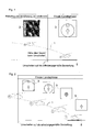
- Fig. 2 shows the display according to the invention in several snapshots during the final approach phase.
- the scale for the representation of the altitude circle and the scale for the representation of the distance between the position of the landing zone and the position of the helicopter are selected such that the symbol for the landing zone intersects at its top with the altitude circle, as long as the pilot of the given landing trajectory follows.
- the landing zone and helicopter symbols are (at least for the most part) within the altitude circle, which is progressively smaller until finally all three symbols merge at the time of landing.
- Fig. 3 shows the display 3 with various representations according to the invention, in which the helicopter does not follow the prescribed parabola.
- the helicopter In the upper illustration the helicopter is too far left on the landing zone.
- the helicopter flies too high, because the symbol for the landing zone from the altitude circle is removed.
- Fig. 4 shows an advantageous embodiment of the representation according to the invention. Usually pass between switching point and landing only a few seconds. However, should this period be extended because the helicopter is hovering above the landing zone, for example, the position calculated by the inertial navigation system may increase (depending on the accuracy of the navigation system). This inaccuracy is accounted for by the increasing stroke strength of the landing zone icon, as in Fig. 4 shown.
- Fig. 5 shows the construction of a system for implementing the method described.
- the computer 12 first calculates the switching time for the representation according to the invention on the display 3 by means of speed (vector) (the provision of this data by the inertial navigation system 10) and possibly other parameters and the height above ground (provided by the Altimeter 11).
- the navigation system 10 is used both for calculating the position of the landing zone and for calculating the altitude circle.
- the altimeter 11 can be used for the calculation of the altitude circle.
- Fig. 6 shows the cockpit of a helicopter in which the inventive method is implemented.
- the display 3 for the representation according to the invention is arranged centrally, directly next to the primary flight display 30, which is set up and certified for the representation of all essential flight parameters such as acceleration, speeds and attitude.
- the display 3 according to the invention serves as an additional aid for the pilot for better orientation in the final landing phase.
- the information presented is limited to the elements described above in order to avoid overloading and distraction of the pilots.
Landscapes
- Engineering & Computer Science (AREA)
- Aviation & Aerospace Engineering (AREA)
- Physics & Mathematics (AREA)
- General Physics & Mathematics (AREA)
- Radar, Positioning & Navigation (AREA)
- Remote Sensing (AREA)
- Traffic Control Systems (AREA)
- Navigation (AREA)
Abstract
Description
- Die Erfindung betrifft ein Verfahren sowie ein entsprechendes System zur Landehilfe für Helikopter.
- Bei Landungen von Helikoptern bei schlechter Sicht (z.B. Landungen bei Nacht, im Schnee, auf Sand) kann es zum Verlust der visuellen Referenz und in deren Folge zu schweren Unfällen kommen (sogenannter Brown-Out oder White-Out).
- Allgemein bekannte Ansätze zur Verbesserung der Sicherheit bei Landungen von Helikoptern sind:
- Prozedurale Maßnahmen: Anwendung von Landeverfahren/-Prozeduren ohne spezielle Systeme zur Landeunterstützung. Die Landungen unter schlechten Sichtbedingungen finden nach vorgegebenen Lande-Prozeduren statt (insbesondere unter Vorgabe der Landetrajektorie, Anflugwinkel, Geschwindigkeit, etc). Hierbei stehen Piloten lediglich Lage-Informationen des Helikopters über Cockpit-Instrumente (hier ist insbesondere das Primary Flight System von Bedeutung) zur Verfügung. Information zur genauen Position, Lage und Beschaffenheit der Landefläche sind dagegen nicht verfügbar. Deshalb erfolgt in Einzelfällen die Einweisung des Piloten (z.B. über Sprechfunk) durch Crew-Mitglieder, die visuellen Kontakt zur Landefläche bzw. zum Helikopter haben. Dieser Ansatz wird beispielsweise von deutschen CH53 Besatzungen angewandt.
- Systeme zur unterstützenden Landung (Landehilfe): Verwendung von spezieller Lande-Sensorik und -Visualisierung. Zur verbesserten Orientierung wird Piloten auf Basis entsprechender Sensoren (Lande-Zonen-Radar, Kamera, Präzisions-Höhenmesser, etc.) über Cockpit-Anzeigen (z.B. Multifunktionsdisplay, Head-up Display, Helmet Mounted Display) die Landezone sowie die Lage und Bewegung des Helikopters dargestellt. Die besagten Systeme zur unterstützenden Landung verwenden unterschiedliche Sensoren oder Datenbanken, um daraus Informationen über die Lage, Position und Beschaffenheit der Landezone zu ermitteln und diese in intuitiver Form den Piloten anzuzeigen. Je nach Ausbaustufe findet eine einfache 2D Lande-Symbolik mit Informationen zur Drift und Lage des Helikopters bis hin zu einer synthetischen Außensicht der Lande-Zone Anwendung. Aufgrund zusätzlicher Sensorik und teilweise aufwändiger Verfahren, wie z.B. Datenfusion, ergeben sich allerdings auch Nachteile. Dazu zählen die hohen System- und Integrationskosten, zusätzliches Gewicht, Kritikalität im Hinblick auf Systemverfügbarkeit/ Zuverlässigkeit/Zulassung und nicht zuletzt die Beschränkung des Einsatzes/Nutzens dieser komplexen Lösungen auf die Landephase.
- Systeme zur autonomen Landung: Unter Verwendung spezieller Lande-Sensorik und des Helikopter-Autopiloten werden Landungen automatisch durchgeführt. Für diese Systeme gelten die oben zu den Systemen zur unterstützenden Landung genannten Nachteile ebenfalls, wenngleich die Systemkritikalität und -Zulassung sowie der damit verbundene Aufwand eine noch größere Herausforderung darstellen.
- Es ist Aufgabe der Erfindung, ein Verfahren zur Landehilfe zu schaffen, das durch die Nutzung der vorhandenen Avionik-Infrastruktur kostengünstig realisiert werden kann und das einfach, intuitiv und übersichtlich gestaltet ist.
- Diese Aufgabe wird durch das Verfahren nach Anspruch 1 gelöst. Ein System zur Implementierung des erfindungsgemäßen Verfahrens sowie vorteilhafte Ausführungen sind Gegenstand von weiteren Ansprüchen.
- Der erfindungsgemäße Ansatz stellt eine Kombination aus den oben beschriebenen Konzepten "Prozedurale Maßnahmen" und "Systemen zur unterstützenden Landung" dar. Dabei können vorhandene Navigationssysteme (z.B. Inertial-Navigationssystem, Höhensensor) in Verbindung mit vorgegebenen Landeprozeduren (welche neben Geschwindigkeiten, Anflugwinkel, etc. eine bestimmte Landetrajektorie implizieren) genutzt werden, um Piloten über Anzeigen (z.B. Multifunktionsdisplay, Head-up Display, Helmet Mounted Display) eine Orientierungshilfe bei Landungen zu geben. Zur Realisierung des erfindungsgemäßen Verfahrens ist somit im Idealfall nur eine Software-Erweiterung notwendig.
- Gemäß der Erfindung erfolgt eine Prädiktion und Anzeige der Landezone während des Landeanflugs auf der Basis eingeführter Lande-Anflugsprozeduren. Das erfindungsgemäße Verfahren erfordert somit die Anwendung/Einhaltung dieser Prozeduren.
- Bevorzugt wird das erfindungsgemäße Verfahren neben dem allein maßgeblichen Primary Flight Display als zusätzliches Mittel zur Orientierung für den Piloten vorgesehen, welches er während der kritischen Landephase als Positionsreferenz (Darstellung der aktuellen Position bezogen auf die Landezone) nutzen kann. In dieser Rolle als zusätzliche Landehilfe neben dem für DAL-A (Design Assurance Level) zugelassenen Primary Flight Display wird für den Betrieb des erfindungsgemäßen Systems nur eine vereinfachte behördliche Flugzulassung benötigt. Um einen permanenten Blickkontakt des Piloten zur erfindungsgemäßen Anzeige zu vermeiden, ist die Darstellung der relevanten Informationen extrem reduziert und beschränkt sich in der bevorzugten Ausführung ausschließlich auf folgende Elemente:
- Darstellung eines Symbols für die Position der auf der Basis einer vorgeschriebenen Landeprozedur berechneten Landezone sowie relativ und positionsgerecht hierzu eines Symbols der momentanen Position des Helikopters,
- Darstellung der momentanen Höhe des Helikopters als Radius eines Kreises, dessen Mittelpunkt von dem Symbol für die momentane Position des Helikopters gebildet wird.
- Auf die Anzeige schnell sich ändernder Informationen wie Beschleunigungen, Geschwindigkeiten oder Fluglage wird in dieser Ausführung bewusst verzichtet, da derartige Informationen bereits über das Primary Flight Display zur Verfügung stehen.
- Die Erfindung wird anhand eines Ausführungsbeispiels unter Bezugnahme auf Figuren näher erläutert. Es zeigen:
- Fig. 1
- die erfindungsgemäße Anzeige sowie die Prädiktion der Landezone während des Landeanflugs;
- Fig. 2
- die erfindungsgemäße Anzeige in mehreren Momentaufnahmen während der finalen Anflugphase;
- Fig. 3
- die erfindungsgemäße Anzeige bei nicht optimalem Anflug der Landezone;
- Fig. 4
- eine vorteilhafte Ausführung der erfindungsgemäßen Anzeige;
- Fig. 5
- das Blockschaltbild eines Systems zur Durchführung des erfindungsgemäßen Verfahrens;
- Fig. 6
- die Darstellung eines Cockpits mit der erfindungsgemäßen Anzeige.
-
Fig. 1 zeigt eine Prinzipdarstellung zum Ablauf des erfindungsgemäßen Verfahrens. Der Landeanflug des Helikopters erfolgt auf der Landetrajektorie 1 entsprechend einer dem Piloten vorgegebenen Landeprozedur. Dabei handelt es sich typischerweise um eine Standardlandeprozedur, die höchstmögliche Sicherheit im Flugbetrieb gewährleisten soll. - Im Reiseflug und zu Beginn des Landeanflugs auf die Landezone 5 hin erfolgt mit der Anzeige 3 noch eine herkömmliche Kartendarstellung in elektronischer Form, z.B. eine an sich bekannte "Moving Map Darstellung" zur Flugnavigation und Orientierung. Diese ist jedoch aufgrund ihrer groben Auflösung zur Orientierung für die weitere Landung ungeeignet. Mit Beginn der finalen Landephase wird diese herkömmliche Kartendarstellung durch die erfindungsgemäße Darstellung ersetzt.
- Unter Berücksichtigung der Landeprozedur (Landetrajektorie 1), der Höhe über Grund, der Sink-Rate und des Geschwindigkeitsvektors des Helikopters wird der Umschaltpunkt für die Kartenanzeige automatisch bestimmt und darüber hinaus die zugehörige Landezone berechnet. Die Umschaltung muss in jedem Fall so frühzeitig erfolgen, dass kritische Situationen wie Brown-Out oder White-Out noch nicht eintreten können.
- Die berechnete Landezone 5 (das erfindungsgemäße Verfahren setzt die Existenz einer für die Landung geeignete Landezone voraus, d.h. insbesondere hinsichtlich Neigung, Größe, Hindernisfreiheit) wird in der erfindungsgemäßen Darstellung auf der Anzeige 3 wiedergegeben, im gezeigten Beispiel ein Symbol, das an ein abstrahiertes Gebäude erinnert (um damit Assoziationen an einen Hangar bzw. eine Parkposition zu erzeugen).
- Des Weiteren ist in der Anzeige ein Symbol für die momentane Position des Helikopters im Bezug zu der berechneten Landezone wiedergegeben. Im weiteren Verlauf der Landung wird zur Berechnung der Helikopter-Position in Relation zur Landezone ein Inertial-Navigationssystem sowie ein Höhensensor verwendet.
- Zur räumlichen Orientierung des Piloten ist um das Helikopter-Symbol ein Kreis dargestellt, dessen Radius der momentanen Höhe des Helikopters über dem Boden entspricht. In der gezeigten Darstellung bleibt das Helikoptersymbol in der Anzeige unbeweglich, während sich die Position der Landezone zusammen mit dem Höhenkreis verändert. Die alternative Darstellung mit einer festen Landezone und einem veränderlichen Helikoptersymbol ist aber äquivalent und stellt ebenfalls eine Lösung im Rahmen der Erfindung dar.
-
Fig. 2 zeigt die erfindungsgemäße Anzeige in mehreren Momentaufnahmen während der finalen Anflugphase. Die Skalierung für die Darstellung des Höhenkreises und die Skalierung für die Darstellung des Abstands zwischen der Position der Landezone und der Position des Helikopters sind derart gewählt, dass das Symbol für die Landezone sich an seiner Spitze mit dem Höhenkreis schneidet, solange der Pilot der vorgegebenen Landetrajektorie folgt. - Bei Befolgung der vorgegebenen Landeprozedur befinden sich also die Symbole für Landezone und Helikopter (zumindest größtenteils) innerhalb des Höhenkreises, welcher fortlaufend kleiner wird, bis schließlich alle drei Symbole im Zeitpunkt der Landung miteinander verschmelzen.
-
Fig. 3 zeigt die Anzeige 3 mit verschiedenen erfindungsgemäßen Darstellungen, bei denen der Helikopter nicht der vorgeschriebenen Parabel folgt. In der oberen Darstellung befindet sich der Helikopter zu weit links bezogen auf die Landezone. Außerdem fliegt der Helikopter zu hoch, da das Symbol für die Landezone vom Höhenkreis entfernt ist. - In der unteren Darstellung von
Fig. 3 befindet sich der Helikopter ebenfalls links ab von der Landezone. Außerdem ist seine Höhe zu gering, da das Symbol für die Landezone außerhalb des Höhenkreises liegt. -
Fig. 4 zeigt eine vorteilhafte Ausführung der erfindungsgemäßen Darstellung. Üblicherweise vergehen zwischen Umschaltpunkt und Landung nur wenige Sekunden. Sollte sich dieser Zeitraum jedoch verlängern, weil der Helikopter z.B. über der Landezone schwebt, kann es (je nach Genauigkeit des Navigationssystems) zu einer zunehmenden Ungenauigkeit der vom Inertial-Navigationssystem berechneten Position kommen. Diese Ungenauigkeit wird durch eine zunehmende Strich-Stärke des Symbols für die Landezone berücksichtigt, wie inFig. 4 dargestellt. -
Fig. 5 zeigt den Aufbau eines Systems zur Implementierung des beschriebenen Verfahrens. - Der Computer 12 berechnet zunächst den Umschalt-Zeitpunkt für die erfindungsgemäße Darstellung auf der Anzeige 3 mittels Geschwindigkeit(-Vektor) (die Bereitstellung dieser Daten erfolgt durch das Inertial-Navigationssystem 10) und ggf. weiteren Parametern sowie der Höhe über Grund (bereitgestellt durch den Höhenmesser 11).
- Im weiteren Verlauf der Landung wird das Navigationssystem 10 sowohl zur Berechnung der Lage der Landezone als auch zur Berechnung des Höhenkreises genutzt. Alternativ oder zusätzlich kann der Höhenmesser 11 für die Berechnung des Höhenkreises genutzt werden.
-
Fig. 6 zeigt das Cockpit eines Helikopters, in dem das erfindungsgemäße Verfahren implementiert ist. Die Anzeige 3 für die erfindungsgemäße Darstellung ist zentral, direkt neben dem Primary Flight Display 30 angeordnet, welches für die Darstellung aller wesentlichen Flugparameter wie Beschleunigung, Geschwindigkeiten und Fluglage eingerichtet und zertifiziert ist. Die erfindungsgemäße Anzeige 3 dient als zusätzliches Hilfsmittel für den Piloten zur besseren Orientierung in der finalen Landephase. Die dargestellten Informationen sind auf die oben beschriebenen Elemente beschränkt, um eine Überlastung und Ablenkung der Piloten zu vermeiden. - Im Folgenden werden nochmals die wesentlichen Vorteile der Erfindung zusammengefasst:
- Es handelt sich um ein intuitives, kostengünstiges und schnell implementierbares Konzept zur Unterstützung von Landungen bei schlechter Sicht (z.B. Staublandung, Schneelandung, Nacht). Besondere Vorteile sind:
- ● Einfache Helikopter Ein- und Nachrüstung (in der Regel über eine SW-Erweiterung) durch Nutzung bereits vorhandener Komponenten;
- ● Einfache Zulassung des Systems:
- Das erfindungsgemäße System kann vorteilhaft als ein unterstützendes System (insbesondere neben dem Primary Flight Display) vorgesehen sein; bereits zugelassene (prozedurale) Landeverfahren gelten unverändert;
- geringe Komplexität der Berechnungen und Visualisierung;
- vereinfachte symbolische Darstellung der Helikopter und Lande-Zonen Position, ohne Anzeige genauer Messwerte sowie ohne Einbeziehung dynamischer Kenngrößen (Geschwindigkeiten, Beschleunigungen, etc.);
- ● Intuitive und logische Darstellung, da auf dem Moving Map Display unmittelbar vor der Landung automatisch die erfindungsgemäße Symbolik dargestellt wird.
Claims (9)
- Verfahren zur Landehilfe für einen Helikopter, mit folgenden Verfahrensschritten:- Berechnung der voraussichtlichen Landezone (5) auf der Basis einer vorgegebenen Landetrajektorie (1),- in einer Anzeige (3): Darstellung eines Symbols für die Position der Landezone (5) sowie relativ hierzu eines Symbols der momentanen Position des Helikopters,- Darstellung der momentanen Höhe des Helikopters als Radius eines Kreises, dessen Mittelpunkt von dem Symbol für die momentane Position des Helikopters gebildet wird.
- Verfahren nach Anspruch 1, dadurch gekennzeichnet, dass die Darstellung des Symbols für die Position der Landezone (5) sowie relativ hierzu des Symbols für die Position des Helikopters mit Bezug auf ein helikopterfestes Koordinatensystem dargestellt wird.
- Verfahren zur Landehilfe nach Anspruch 2, dadurch gekennzeichnet, dass auf der Anzeige (3) die Skalierung für die Darstellung des Höhenkreises und die Skalierung für die Darstellung des Abstands zwischen Position der Landezone (5) und Position des Helikopters derart gewählt werden, dass der Helikopter der vorgegebenen Landetrajektorie (1) folgt, solange das Symbol für der Landezone (5) sich am Höhenkreises befindet oder diesen schneidet.
- Verfahren zur Landehilfe nach einem der vorangehenden Ansprüche, dadurch gekennzeichnet, dass die Strichstärke des Symbols für die Position der Landezone erhöht wird, wenn der Landeanflug eine vorgegebene Zeitdauer überschreitet.
- Verfahren zur Landehilfe nach einem der vorangehenden Ansprüche, dadurch gekennzeichnet, dass die Landetrajektorie (1) eine hinsichtlich Flugsicherheit optimierte Trajektorie ist.
- System zur Landehilfe für einen Helikopter,- mit einem Computer (12) zur Berechnung der voraussichtlichen Landezone auf der Basis einer vorgegebenen Landetrajektorie (1),- einem Navigationssystem (10) zur Ermittlung der momentanen Position und der momentanen Höhe des Helikopters,- einer Anzeige (3), eingerichtet zur Darstellung eines Symbols für die Position der Landezone und relativ hierzu einem Symbol zur Darstellung eines Symbols für die momentane Position des Helikopters sowie einer Darstellung der momentanen Höhe des Helikopters als Radius eines Kreises, dessen Mittelpunkt von dem Symbol für die momentane Position des Helikopters gebildet wird.
- System nach Anspruch 6, dadurch gekennzeichnet, dass die Darstellung des Symbols für die Position der Landezone (5) sowie relativ hierzu des Symbols für die Position des Helikopters mit Bezug auf ein helikopterfestes Koordinatensystem dargestellt wird.
- System nach Anspruch 7, dadurch gekennzeichnet, dass in der Anzeige (3) die Skalierung für die Darstellung des Höhenkreises und die Skalierung für die Darstellung des Abstands zwischen Position der Landezone (5) und Position des Helikopters derart eingestellt ist, dass der Helikopter der vorgegebenen Landetrajektorie (5) folgt, solange das Symbol für die Landezone (5) sich am Höhenkreises befindet oder diesen schneidet.
- System nach einem der Ansprüche 6 bis 8, umfassend einen Höhenmesser (11), der anstatt oder zusätzlich zu dem Navigationssystem die momentane Position des Helikopters ermittelt.
Priority Applications (3)
| Application Number | Priority Date | Filing Date | Title |
|---|---|---|---|
| PL12000345T PL2618110T3 (pl) | 2012-01-20 | 2012-01-20 | Sposób i system pomocy w lądowaniu helikopterów |
| EP12000345.4A EP2618110B1 (de) | 2012-01-20 | 2012-01-20 | Verfahren und System zur Landehilfe für Helikopter |
| ES12000345T ES2530366T3 (es) | 2012-01-20 | 2012-01-20 | Procedimiento y sistema de asistencia al aterrizaje para helicópteros |
Applications Claiming Priority (1)
| Application Number | Priority Date | Filing Date | Title |
|---|---|---|---|
| EP12000345.4A EP2618110B1 (de) | 2012-01-20 | 2012-01-20 | Verfahren und System zur Landehilfe für Helikopter |
Publications (2)
| Publication Number | Publication Date |
|---|---|
| EP2618110A1 true EP2618110A1 (de) | 2013-07-24 |
| EP2618110B1 EP2618110B1 (de) | 2014-11-12 |
Family
ID=45531750
Family Applications (1)
| Application Number | Title | Priority Date | Filing Date |
|---|---|---|---|
| EP12000345.4A Active EP2618110B1 (de) | 2012-01-20 | 2012-01-20 | Verfahren und System zur Landehilfe für Helikopter |
Country Status (3)
| Country | Link |
|---|---|
| EP (1) | EP2618110B1 (de) |
| ES (1) | ES2530366T3 (de) |
| PL (1) | PL2618110T3 (de) |
Cited By (2)
| Publication number | Priority date | Publication date | Assignee | Title |
|---|---|---|---|---|
| CN109613923A (zh) * | 2018-11-06 | 2019-04-12 | 武汉华中天经通视科技有限公司 | 一种无人直升机的着舰控制方法 |
| FR3077875A1 (fr) * | 2018-02-15 | 2019-08-16 | Helper-Drone | Dispositif de cartographie tactique evolutive dans un environnement exterieur, systeme et procede associes |
Citations (3)
| Publication number | Priority date | Publication date | Assignee | Title |
|---|---|---|---|---|
| US20050206533A1 (en) * | 2003-03-22 | 2005-09-22 | Rogers Steven P | Aircraft future position and flight path indicator symbology |
| EP1906151A2 (de) * | 2006-09-29 | 2008-04-02 | Applied Minds, Inc. | Abbildungs- und Anzeigesystem zur Unterstützung von Hubschrauberlandungen unter Netzspannungsabsenkungsbedingungen |
| US20120004793A1 (en) * | 2010-07-02 | 2012-01-05 | Sandel Avionics, Inc. | Aircraft hover system and method |
-
2012
- 2012-01-20 ES ES12000345T patent/ES2530366T3/es active Active
- 2012-01-20 EP EP12000345.4A patent/EP2618110B1/de active Active
- 2012-01-20 PL PL12000345T patent/PL2618110T3/pl unknown
Patent Citations (3)
| Publication number | Priority date | Publication date | Assignee | Title |
|---|---|---|---|---|
| US20050206533A1 (en) * | 2003-03-22 | 2005-09-22 | Rogers Steven P | Aircraft future position and flight path indicator symbology |
| EP1906151A2 (de) * | 2006-09-29 | 2008-04-02 | Applied Minds, Inc. | Abbildungs- und Anzeigesystem zur Unterstützung von Hubschrauberlandungen unter Netzspannungsabsenkungsbedingungen |
| US20120004793A1 (en) * | 2010-07-02 | 2012-01-05 | Sandel Avionics, Inc. | Aircraft hover system and method |
Cited By (3)
| Publication number | Priority date | Publication date | Assignee | Title |
|---|---|---|---|---|
| FR3077875A1 (fr) * | 2018-02-15 | 2019-08-16 | Helper-Drone | Dispositif de cartographie tactique evolutive dans un environnement exterieur, systeme et procede associes |
| WO2019158880A1 (fr) * | 2018-02-15 | 2019-08-22 | Helper-Drone | Dispositif de cartographie tactique évolutive dans un environnement extérieur, système et procédé associés |
| CN109613923A (zh) * | 2018-11-06 | 2019-04-12 | 武汉华中天经通视科技有限公司 | 一种无人直升机的着舰控制方法 |
Also Published As
| Publication number | Publication date |
|---|---|
| PL2618110T3 (pl) | 2015-08-31 |
| ES2530366T3 (es) | 2015-03-02 |
| EP2618110B1 (de) | 2014-11-12 |
Similar Documents
| Publication | Publication Date | Title |
|---|---|---|
| DE69910344T2 (de) | Cockpitanzeige mit dreidimensionaler Flugbahnabweichungssymbolik | |
| EP2166372B1 (de) | Mensch-Maschinen-Interface zur Pilotenunterstützung bei Start oder Landung eines Fluggeräts unter verminderter Außensicht | |
| US9058742B2 (en) | Methods for illustrating aircraft situational information | |
| DE60113552T2 (de) | Intuitives fahrzeug und maschinensteuerung | |
| EP1653250B1 (de) | Integriertes system für flugzeug-wirbelsicherheit | |
| EP2492890B1 (de) | Flugzeugsystem und Verfahren zur Anzeige visueller Segmentinformationen | |
| DE102013102624A1 (de) | Piloten-Briefinginstrument zur Situationserfassung | |
| EP1972896B1 (de) | Mensch-Maschinen-Interface zur Pilotenunterstützung bei Start und Landung eines Fluggerät bei verminderter Außensicht | |
| DE102005022231B4 (de) | Verfahren und Vorrichtung zur Darstellung des Lage und des Bewegungszustands einer pendelfähigen Last | |
| DE60002835T2 (de) | Verfahren und vorrichtung zur erzeugung einer bodennäherungswarnung und computerprogramm zum kontrollierten verändern der basisbreite einer alarmhülle | |
| DE60121944T2 (de) | Verfahren und vorrichtung zum anzeigen von navigationsinformationen im echtzeitbetrieb | |
| DE102017130714B4 (de) | Pilotenunterstützung mittels Augmented Reality | |
| EP3566925B1 (de) | (teil-) autonomes kraftfahrzeug und verfahren zum betreiben desselben | |
| DE60307928T2 (de) | Vorrichtung zur Unterstützung der visuellen Postitionsbestimmung eines Flugzeuges während des Fluges | |
| EP2618110B1 (de) | Verfahren und System zur Landehilfe für Helikopter | |
| DE3417884A1 (de) | Verfahren und vorrichtung zur anzeige eines gefaehrlichen flugprofils bei flugbewegungen in geringer hoehe | |
| DE10140676B4 (de) | Bahnführungs-Systeme für einen Fall- oder Gleitschirm und Flugbahn-Planungseinrichtungen zur Planung des Einsatzes zumindest eines Fall- oder Gleitschirms sowie Verfahren zur Durchführung der Bahnführung und der Planung | |
| DE202012105058U1 (de) | Navigationsvorrichtung für Flugzeuge | |
| US10035608B2 (en) | Methods and devices for assisting the piloting of an aircraft during at least one flight phase having a plurality of steering steps | |
| DE10005175A1 (de) | Verfahren und Vorrichtung zur Warnung vor Kollisionen von Flugzeugen | |
| DE102014104572B4 (de) | Geschwindigkeitsanzeige | |
| US20120016540A1 (en) | Method And Device For Aiding The Control Of Guiding Modes Transitions Of An Aircraft | |
| EP3299768B1 (de) | Mensch-maschinen-interface für den piloten eines fluggeräts | |
| DE102014104724B4 (de) | Außenlastbewegungsanzeige | |
| Fujizawa et al. | Degraded visual environment mitigation program NATO flight trials: US army flight test and results |
Legal Events
| Date | Code | Title | Description |
|---|---|---|---|
| PUAI | Public reference made under article 153(3) epc to a published international application that has entered the european phase |
Free format text: ORIGINAL CODE: 0009012 |
|
| AK | Designated contracting states |
Kind code of ref document: A1 Designated state(s): AL AT BE BG CH CY CZ DE DK EE ES FI FR GB GR HR HU IE IS IT LI LT LU LV MC MK MT NL NO PL PT RO RS SE SI SK SM TR |
|
| AX | Request for extension of the european patent |
Extension state: BA ME |
|
| 17P | Request for examination filed |
Effective date: 20131204 |
|
| RBV | Designated contracting states (corrected) |
Designated state(s): AL AT BE BG CH CY CZ DE DK EE ES FI FR GB GR HR HU IE IS IT LI LT LU LV MC MK MT NL NO PL PT RO RS SE SI SK SM TR |
|
| REG | Reference to a national code |
Ref country code: DE Ref legal event code: R079 Ref document number: 502012001549 Country of ref document: DE Free format text: PREVIOUS MAIN CLASS: G01C0023000000 Ipc: G08G0005000000 |
|
| RIC1 | Information provided on ipc code assigned before grant |
Ipc: G08G 5/00 20060101AFI20140415BHEP Ipc: G08G 5/02 20060101ALI20140415BHEP Ipc: G01C 23/00 20060101ALI20140415BHEP |
|
| GRAP | Despatch of communication of intention to grant a patent |
Free format text: ORIGINAL CODE: EPIDOSNIGR1 |
|
| INTG | Intention to grant announced |
Effective date: 20140630 |
|
| GRAS | Grant fee paid |
Free format text: ORIGINAL CODE: EPIDOSNIGR3 |
|
| RAP1 | Party data changed (applicant data changed or rights of an application transferred) |
Owner name: AIRBUS DEFENCE AND SPACE GMBH |
|
| GRAA | (expected) grant |
Free format text: ORIGINAL CODE: 0009210 |
|
| AK | Designated contracting states |
Kind code of ref document: B1 Designated state(s): AL AT BE BG CH CY CZ DE DK EE ES FI FR GB GR HR HU IE IS IT LI LT LU LV MC MK MT NL NO PL PT RO RS SE SI SK SM TR |
|
| REG | Reference to a national code |
Ref country code: GB Ref legal event code: FG4D Free format text: NOT ENGLISH |
|
| REG | Reference to a national code |
Ref country code: CH Ref legal event code: EP |
|
| REG | Reference to a national code |
Ref country code: AT Ref legal event code: REF Ref document number: 696162 Country of ref document: AT Kind code of ref document: T Effective date: 20141115 |
|
| REG | Reference to a national code |
Ref country code: IE Ref legal event code: FG4D Free format text: LANGUAGE OF EP DOCUMENT: GERMAN |
|
| REG | Reference to a national code |
Ref country code: DE Ref legal event code: R096 Ref document number: 502012001549 Country of ref document: DE Effective date: 20141224 |
|
| REG | Reference to a national code |
Ref country code: NL Ref legal event code: T3 |
|
| REG | Reference to a national code |
Ref country code: ES Ref legal event code: FG2A Ref document number: 2530366 Country of ref document: ES Kind code of ref document: T3 Effective date: 20150302 |
|
| REG | Reference to a national code |
Ref country code: SE Ref legal event code: TRGR |
|
| REG | Reference to a national code |
Ref country code: NO Ref legal event code: T2 Effective date: 20141112 |
|
| PG25 | Lapsed in a contracting state [announced via postgrant information from national office to epo] |
Ref country code: IS Free format text: LAPSE BECAUSE OF FAILURE TO SUBMIT A TRANSLATION OF THE DESCRIPTION OR TO PAY THE FEE WITHIN THE PRESCRIBED TIME-LIMIT Effective date: 20150312 Ref country code: LT Free format text: LAPSE BECAUSE OF FAILURE TO SUBMIT A TRANSLATION OF THE DESCRIPTION OR TO PAY THE FEE WITHIN THE PRESCRIBED TIME-LIMIT Effective date: 20141112 Ref country code: PT Free format text: LAPSE BECAUSE OF FAILURE TO SUBMIT A TRANSLATION OF THE DESCRIPTION OR TO PAY THE FEE WITHIN THE PRESCRIBED TIME-LIMIT Effective date: 20150312 Ref country code: FI Free format text: LAPSE BECAUSE OF FAILURE TO SUBMIT A TRANSLATION OF THE DESCRIPTION OR TO PAY THE FEE WITHIN THE PRESCRIBED TIME-LIMIT Effective date: 20141112 |
|
| PG25 | Lapsed in a contracting state [announced via postgrant information from national office to epo] |
Ref country code: LV Free format text: LAPSE BECAUSE OF FAILURE TO SUBMIT A TRANSLATION OF THE DESCRIPTION OR TO PAY THE FEE WITHIN THE PRESCRIBED TIME-LIMIT Effective date: 20141112 Ref country code: RS Free format text: LAPSE BECAUSE OF FAILURE TO SUBMIT A TRANSLATION OF THE DESCRIPTION OR TO PAY THE FEE WITHIN THE PRESCRIBED TIME-LIMIT Effective date: 20141112 Ref country code: HR Free format text: LAPSE BECAUSE OF FAILURE TO SUBMIT A TRANSLATION OF THE DESCRIPTION OR TO PAY THE FEE WITHIN THE PRESCRIBED TIME-LIMIT Effective date: 20141112 Ref country code: CY Free format text: LAPSE BECAUSE OF FAILURE TO SUBMIT A TRANSLATION OF THE DESCRIPTION OR TO PAY THE FEE WITHIN THE PRESCRIBED TIME-LIMIT Effective date: 20141112 Ref country code: GR Free format text: LAPSE BECAUSE OF FAILURE TO SUBMIT A TRANSLATION OF THE DESCRIPTION OR TO PAY THE FEE WITHIN THE PRESCRIBED TIME-LIMIT Effective date: 20150213 |
|
| PG25 | Lapsed in a contracting state [announced via postgrant information from national office to epo] |
Ref country code: EE Free format text: LAPSE BECAUSE OF FAILURE TO SUBMIT A TRANSLATION OF THE DESCRIPTION OR TO PAY THE FEE WITHIN THE PRESCRIBED TIME-LIMIT Effective date: 20141112 Ref country code: DK Free format text: LAPSE BECAUSE OF FAILURE TO SUBMIT A TRANSLATION OF THE DESCRIPTION OR TO PAY THE FEE WITHIN THE PRESCRIBED TIME-LIMIT Effective date: 20141112 Ref country code: SK Free format text: LAPSE BECAUSE OF FAILURE TO SUBMIT A TRANSLATION OF THE DESCRIPTION OR TO PAY THE FEE WITHIN THE PRESCRIBED TIME-LIMIT Effective date: 20141112 Ref country code: CZ Free format text: LAPSE BECAUSE OF FAILURE TO SUBMIT A TRANSLATION OF THE DESCRIPTION OR TO PAY THE FEE WITHIN THE PRESCRIBED TIME-LIMIT Effective date: 20141112 Ref country code: RO Free format text: LAPSE BECAUSE OF FAILURE TO SUBMIT A TRANSLATION OF THE DESCRIPTION OR TO PAY THE FEE WITHIN THE PRESCRIBED TIME-LIMIT Effective date: 20141112 |
|
| REG | Reference to a national code |
Ref country code: DE Ref legal event code: R097 Ref document number: 502012001549 Country of ref document: DE |
|
| PG25 | Lapsed in a contracting state [announced via postgrant information from national office to epo] |
Ref country code: LU Free format text: LAPSE BECAUSE OF FAILURE TO SUBMIT A TRANSLATION OF THE DESCRIPTION OR TO PAY THE FEE WITHIN THE PRESCRIBED TIME-LIMIT Effective date: 20150120 |
|
| REG | Reference to a national code |
Ref country code: PL Ref legal event code: T3 |
|
| PLBE | No opposition filed within time limit |
Free format text: ORIGINAL CODE: 0009261 |
|
| STAA | Information on the status of an ep patent application or granted ep patent |
Free format text: STATUS: NO OPPOSITION FILED WITHIN TIME LIMIT |
|
| PG25 | Lapsed in a contracting state [announced via postgrant information from national office to epo] |
Ref country code: MC Free format text: LAPSE BECAUSE OF FAILURE TO SUBMIT A TRANSLATION OF THE DESCRIPTION OR TO PAY THE FEE WITHIN THE PRESCRIBED TIME-LIMIT Effective date: 20141112 |
|
| 26N | No opposition filed |
Effective date: 20150813 |
|
| REG | Reference to a national code |
Ref country code: IE Ref legal event code: MM4A |
|
| REG | Reference to a national code |
Ref country code: FR Ref legal event code: PLFP Year of fee payment: 5 |
|
| PG25 | Lapsed in a contracting state [announced via postgrant information from national office to epo] |
Ref country code: IE Free format text: LAPSE BECAUSE OF NON-PAYMENT OF DUE FEES Effective date: 20150120 |
|
| PG25 | Lapsed in a contracting state [announced via postgrant information from national office to epo] |
Ref country code: SI Free format text: LAPSE BECAUSE OF FAILURE TO SUBMIT A TRANSLATION OF THE DESCRIPTION OR TO PAY THE FEE WITHIN THE PRESCRIBED TIME-LIMIT Effective date: 20141112 |
|
| REG | Reference to a national code |
Ref country code: DE Ref legal event code: R081 Ref document number: 502012001549 Country of ref document: DE Owner name: AIRBUS DS ELECTRONICS AND BORDER SECURITY GMBH, DE Free format text: FORMER OWNER: AIRBUS DEFENCE AND SPACE GMBH, 85521 OTTOBRUNN, DE Ref country code: DE Ref legal event code: R081 Ref document number: 502012001549 Country of ref document: DE Owner name: HENSOLDT SENSORS GMBH, DE Free format text: FORMER OWNER: AIRBUS DEFENCE AND SPACE GMBH, 85521 OTTOBRUNN, DE |
|
| PG25 | Lapsed in a contracting state [announced via postgrant information from national office to epo] |
Ref country code: MT Free format text: LAPSE BECAUSE OF FAILURE TO SUBMIT A TRANSLATION OF THE DESCRIPTION OR TO PAY THE FEE WITHIN THE PRESCRIBED TIME-LIMIT Effective date: 20141112 |
|
| REG | Reference to a national code |
Ref country code: FR Ref legal event code: PLFP Year of fee payment: 6 |
|
| PG25 | Lapsed in a contracting state [announced via postgrant information from national office to epo] |
Ref country code: SM Free format text: LAPSE BECAUSE OF FAILURE TO SUBMIT A TRANSLATION OF THE DESCRIPTION OR TO PAY THE FEE WITHIN THE PRESCRIBED TIME-LIMIT Effective date: 20141112 Ref country code: BG Free format text: LAPSE BECAUSE OF FAILURE TO SUBMIT A TRANSLATION OF THE DESCRIPTION OR TO PAY THE FEE WITHIN THE PRESCRIBED TIME-LIMIT Effective date: 20141112 Ref country code: HU Free format text: LAPSE BECAUSE OF FAILURE TO SUBMIT A TRANSLATION OF THE DESCRIPTION OR TO PAY THE FEE WITHIN THE PRESCRIBED TIME-LIMIT; INVALID AB INITIO Effective date: 20120120 |
|
| PG25 | Lapsed in a contracting state [announced via postgrant information from national office to epo] |
Ref country code: BE Free format text: LAPSE BECAUSE OF NON-PAYMENT OF DUE FEES Effective date: 20150131 |
|
| REG | Reference to a national code |
Ref country code: DE Ref legal event code: R082 Ref document number: 502012001549 Country of ref document: DE Representative=s name: LIFETECH IP SPIES & BEHRNDT PATENTANWAELTE PAR, DE Ref country code: DE Ref legal event code: R081 Ref document number: 502012001549 Country of ref document: DE Owner name: HENSOLDT SENSORS GMBH, DE Free format text: FORMER OWNER: AIRBUS DS ELECTRONICS AND BORDER SECURITY GMBH, 82024 TAUFKIRCHEN, DE |
|
| PG25 | Lapsed in a contracting state [announced via postgrant information from national office to epo] |
Ref country code: TR Free format text: LAPSE BECAUSE OF FAILURE TO SUBMIT A TRANSLATION OF THE DESCRIPTION OR TO PAY THE FEE WITHIN THE PRESCRIBED TIME-LIMIT Effective date: 20141112 |
|
| REG | Reference to a national code |
Ref country code: FR Ref legal event code: PLFP Year of fee payment: 7 |
|
| REG | Reference to a national code |
Ref country code: AT Ref legal event code: MM01 Ref document number: 696162 Country of ref document: AT Kind code of ref document: T Effective date: 20170120 |
|
| PG25 | Lapsed in a contracting state [announced via postgrant information from national office to epo] |
Ref country code: AT Free format text: LAPSE BECAUSE OF NON-PAYMENT OF DUE FEES Effective date: 20170120 |
|
| PG25 | Lapsed in a contracting state [announced via postgrant information from national office to epo] |
Ref country code: MK Free format text: LAPSE BECAUSE OF FAILURE TO SUBMIT A TRANSLATION OF THE DESCRIPTION OR TO PAY THE FEE WITHIN THE PRESCRIBED TIME-LIMIT Effective date: 20141112 |
|
| REG | Reference to a national code |
Ref country code: NO Ref legal event code: CHAD Owner name: HENSOLDT SENSORS GMBH, DE Ref country code: NO Ref legal event code: CHAD Owner name: AIRBUS DS ELECTRONICS AND BORDER SECURITY GM, DE Ref country code: NO Ref legal event code: CREP Representative=s name: TANDBERG INNOVATION AS, POSTBOKS 1570 VIKA, 0118 |
|
| REG | Reference to a national code |
Ref country code: ES Ref legal event code: PC2A Owner name: HENSOLDT SENSORS GMBH Effective date: 20181001 |
|
| PG25 | Lapsed in a contracting state [announced via postgrant information from national office to epo] |
Ref country code: AL Free format text: LAPSE BECAUSE OF FAILURE TO SUBMIT A TRANSLATION OF THE DESCRIPTION OR TO PAY THE FEE WITHIN THE PRESCRIBED TIME-LIMIT Effective date: 20141112 |
|
| REG | Reference to a national code |
Ref country code: CH Ref legal event code: PFA Owner name: HENSOLDT SENSORS GMBH, DE Free format text: FORMER OWNER: AIRBUS DS ELECTRONICS AND BORDER SECURITY GMBH, DE Ref country code: CH Ref legal event code: PUE Owner name: AIRBUS DS ELECTRONICS AND BORDER SECURITY GMBH, DE Free format text: FORMER OWNER: AIRBUS DEFENCE AND SPACE GMBH, DE |
|
| REG | Reference to a national code |
Ref country code: NL Ref legal event code: HC Owner name: HENSOLDT SENSORS GMBH; DE Free format text: DETAILS ASSIGNMENT: CHANGE OF OWNER(S), CHANGE OF OWNER(S) NAME; FORMER OWNER NAME: AIRBUS DS ELECTRONICS AND BORDER SECURITY GMBH Effective date: 20181017 Ref country code: NL Ref legal event code: PD Owner name: AIRBUS DS ELECTRONICS AND BORDER SECURITY GMBH; DE Free format text: DETAILS ASSIGNMENT: CHANGE OF OWNER(S), ASSIGNMENT; FORMER OWNER NAME: AIRBUS DEFENCE AND SPACE GMBH Effective date: 20181017 |
|
| REG | Reference to a national code |
Ref country code: GB Ref legal event code: 732E Free format text: REGISTERED BETWEEN 20181203 AND 20181205 |
|
| PGFP | Annual fee paid to national office [announced via postgrant information from national office to epo] |
Ref country code: NO Payment date: 20230120 Year of fee payment: 12 Ref country code: FR Payment date: 20230123 Year of fee payment: 12 |
|
| PGFP | Annual fee paid to national office [announced via postgrant information from national office to epo] |
Ref country code: SE Payment date: 20230123 Year of fee payment: 12 Ref country code: PL Payment date: 20230105 Year of fee payment: 12 Ref country code: IT Payment date: 20230131 Year of fee payment: 12 |
|
| PGFP | Annual fee paid to national office [announced via postgrant information from national office to epo] |
Ref country code: NL Payment date: 20240122 Year of fee payment: 13 |
|
| PGFP | Annual fee paid to national office [announced via postgrant information from national office to epo] |
Ref country code: ES Payment date: 20240216 Year of fee payment: 13 |
|
| PGFP | Annual fee paid to national office [announced via postgrant information from national office to epo] |
Ref country code: DE Payment date: 20240119 Year of fee payment: 13 Ref country code: GB Payment date: 20240122 Year of fee payment: 13 Ref country code: CH Payment date: 20240202 Year of fee payment: 13 |