EP2618084B1 - Storage device with a flap fastening device and domestic cooler appliance with such a storage device - Google Patents
Storage device with a flap fastening device and domestic cooler appliance with such a storage device Download PDFInfo
- Publication number
- EP2618084B1 EP2618084B1 EP13150439.1A EP13150439A EP2618084B1 EP 2618084 B1 EP2618084 B1 EP 2618084B1 EP 13150439 A EP13150439 A EP 13150439A EP 2618084 B1 EP2618084 B1 EP 2618084B1
- Authority
- EP
- European Patent Office
- Prior art keywords
- flap
- shelf
- fastening device
- designed
- storage device
- Prior art date
- Legal status (The legal status is an assumption and is not a legal conclusion. Google has not performed a legal analysis and makes no representation as to the accuracy of the status listed.)
- Active
Links
Images


Classifications
-
- F—MECHANICAL ENGINEERING; LIGHTING; HEATING; WEAPONS; BLASTING
- F25—REFRIGERATION OR COOLING; COMBINED HEATING AND REFRIGERATION SYSTEMS; HEAT PUMP SYSTEMS; MANUFACTURE OR STORAGE OF ICE; LIQUEFACTION SOLIDIFICATION OF GASES
- F25D—REFRIGERATORS; COLD ROOMS; ICE-BOXES; COOLING OR FREEZING APPARATUS NOT OTHERWISE PROVIDED FOR
- F25D25/00—Charging, supporting, and discharging the articles to be cooled
- F25D25/02—Charging, supporting, and discharging the articles to be cooled by shelves
- F25D25/024—Slidable shelves
-
- F—MECHANICAL ENGINEERING; LIGHTING; HEATING; WEAPONS; BLASTING
- F25—REFRIGERATION OR COOLING; COMBINED HEATING AND REFRIGERATION SYSTEMS; HEAT PUMP SYSTEMS; MANUFACTURE OR STORAGE OF ICE; LIQUEFACTION SOLIDIFICATION OF GASES
- F25D—REFRIGERATORS; COLD ROOMS; ICE-BOXES; COOLING OR FREEZING APPARATUS NOT OTHERWISE PROVIDED FOR
- F25D25/00—Charging, supporting, and discharging the articles to be cooled
- F25D25/02—Charging, supporting, and discharging the articles to be cooled by shelves
Definitions
- the invention relates to a storage device and a household refrigerator with a shelf.
- the US 4,225,203 discloses a household refrigerator having an inner container with a coolable interior.
- an inner container with a coolable interior.
- several plastic shelves are arranged, which are each provided with a front flap.
- DE 10 2008 043 615 A1 discloses a refrigerator with an insulated interior, at least one support for delimiting a compartment in the interior and a flap for separately closing the compartment, wherein the side walls of the interior are each a component connected to which both a bearing for the flap and a Holder are provided for the carrier.
- DE 10 2008 063 390 A1 discloses a refrigerator with one or more shelves in its at least one inner container, along at least one edge portion of the respective shelf a rim or frame is attached, and on the skirt or framing of the respective shelf along a partial length or the total length of their extension additionally at least one Snap, plug and / or clamped connection.
- Object of the present invention is to provide an improved storage device.
- a storage device comprising a flat, in particular rectangular and side edges having shelf, a flap fastening device for pivotally supporting a flap on the flat, in particular rectangular and side edges having shelf, wherein the flap fastening device is made in one piece and a fastening device with the the flap fastening device is mounted on the side edge of the tray, and has a storage device by means of which the flap is pivotally mounted relative to the tray and a flap pivotally mounted by the flap fastener relative to the tray, the flap fastener being an attachment mounted to the tray, and in which the fastening device is U-shaped and has an upper wall, a lower wall and a rear wall, which form a groove whose width is adapted to the thickness of the tray so that the plugged onto the side edges flap fastening device stuck on the side edge.
- a household refrigerating appliance comprising an inner container with a coolable interior, a cooling device provided for cooling the interior, which is designed in particular as a refrigerant circuit, a door opening provided for opening and closing the interior, and a storage device according to the invention arranged inside the interior , wherein the storage plate of the storage device is designed as a arranged on the inner container shelf.
- the domestic refrigerator according to the invention is for example a household refrigerator, a household refrigerator or a fridge freezer. That to open and close the door provided with the coolable interior is preferably pivotably mounted relative to the inner container with respect to a vertical axis.
- the invention integrally executed flap fastening device which is preferably made of plastic by injection molding, is therefore provided to pivotally support a flap relative to the tray.
- the flap attachment device can be plugged onto the side edge of the tray, making it possible to subsequently provide the tray with the hinged flap, so also subsequently a flat, rectangular and side edges having tray with the flap and the flap fastening device to provide the To obtain inventive storage device.
- the tray is e.g. made of glass. Other materials are also possible.
- the flap fastening device according to the invention comprises the storage device.
- the shelf represents a shelf, which is located within the coolable interior of the household refrigerator.
- the household refrigerator according to the invention provides an improved domestic refrigerator with a shelf, which is provided with a flap.
- the flap fastening device is designed as a pin which is intended to engage in an opening or a recess of the flap.
- the storage device according to the invention comprises two flap fastening devices according to the invention, one of which is placed on the left and the other on the right side edge of the shelf, ie on both side edges of the shelf plate respectively a flap fastening device according to the invention are inserted, which are preferably mirror-inverted, so that their pin zueinender are turned so that an axis, with respect to which the flap is pivotally mounted, passes through the pins.
- the flap fastening device according to the invention comprises two flap fastening devices according to the invention, one of which is placed on the left and the other on the right side edge of the shelf, ie on both side edges of the shelf plate respectively a flap fastening device according to the invention are inserted, which are preferably mirror-inverted, so that their pin zueinender are turned so that an axis, with respect to which the flap is pivotally mounted, passes through the pins.
- the flap fastening device according to the invention In order to put the flap fastening device relatively easily on the shelf, whose attachment device is U-shaped and has an upper wall, a lower wall and a rear wall, which form a groove. For a relatively good hold on the tray, it is provided that the width of the groove of the thickness of the tray is adjusted so that the plugged onto the side edges flap fastening device stuck on the side edge.
- the U-shaped fastening device may have a front wall whose outwardly directed side serves as a lower stop, which limits pivotal movement of the flap down relative to the tray.
- the flap fastening device has an upper stop which is provided to limit a pivoting movement of the flap upwards relative to the placement plate in such a way that the flap is oriented at right angles to the placement plate in a folded-up position.
- the folded flap closes the shelf or the shelf at the front, especially when used in household refrigeration appliance and it is prevented that the flap works on the upwardly directed surface of the shelf or the shelf.
- the top stop of the flap fastener may have a flat wall which is directed forwardly and upwardly with respect to the fastener and intended to limit pivotal movement of the flap upwardly relative to the shelf.
- the flat wall provides a relatively large-scale stop for the flap.
- the flap fastening device can have an upwardly projecting web, with the upper edge of which an undercut of the flap locks in its raised position. As a result, at least the risk of unintentional downward pivoting of the flap is reduced.
- the web may preferably be formed as the upper stop, so that the upper edge, with which the undercut of the flap locked in the folded-up position, the upper edge of the upper stop.
- the fastening device of the flap fastening device comprises fixing means, which cooperate with counter-fixing means for fixing the flap fastening device inside the interior.
- the fixing means are attracted in particular to the direction of the interior side of the inner container. Due to the fixing means, the flap fastening device is fixed to the shelf and in the coolable interior, whereby e.g. a risk of jamming the flap is reduced.
- projections may be tightened by means of which the shelf is stored and / or fixed.
- the projections are in particular formed as ribs on which e.g. the shelf rests.
- one of these projections comprises the counter-fixing means. This allows the Jacobfixierstoff be realized with relatively little effort.
- the fixing means may be formed, for example, as a recess in the lower wall of the fastening device of the flap fastening device and the counter-fixing device as a recess cooperating with the recess.
- the bulge may preferably be formed on one of the ribs.
- the fixing means can also be designed, for example, as a latching device formed in the lower wall of the U-shaped fastening device and the counterfixing means as a counter-latching device cooperating with the latching device, which latching device is in particular formed on one of the ribs. This also makes it possible that the flap fastening device is automatically fixed when inserting the shelf in the interior of the household refrigerator, thereby automatically a positionally accurate alignment of the flap fastening device is achieved.
- the latching device may preferably be formed as a downwardly inclined latching tongue and the counter-latching device as a recess in one of the ribs.
- the invention thus provides a flap attachment to a particular designed as a glass plate shelf.
- the household refrigerator can thus be dispensed with a relatively complicated storage of the flap on the inner container.
- a storage compartment can be separated via the flap.
- the Fig. 1 shows a household refrigerator 1, which has an inner container 2 with a coolable interior, which is divided in the case of the present embodiment in a freezer compartment 3 and arranged below the freezer compartment 3 refrigerator 4.
- the freezer compartment 3 is used, for example, for freezing frozen food at, for example, about minus 18 degrees Celsius.
- the domestic refrigerator 1 comprises at least one refrigerant circuit for cooling the freezer compartment 3 and the refrigerator compartment 4.
- a common refrigerant circuit may be provided, e.g. a provided for cooling the cooling chamber 4 evaporator and provided for cooling the freezer compartment 3 evaporator comprises.
- the household refrigerator 1 may also have separate refrigerant circuits for the freezer compartment 3 and the refrigerator 4.
- the door leaves 5, 6 open the freezer compartment 3 and the refrigerator 4 are accessible.
- On the directed towards the refrigerator 4 side of the door provided for closing the refrigerator 4 door leaf 6 a plurality of door racks 7 are arranged for storing refrigerated goods in the case of the present embodiment.
- a drawer 9 is arranged, can be stored in the refrigerated goods.
- the household refrigerator 1 further comprises a control device, not shown, which is adapted to control the or the refrigerant circuits during operation of the household refrigerator 1 such that the freezer compartment 3 and the refrigerator 4 have at least approximately predetermined or adjustable target temperatures, as the Professional is known in principle.
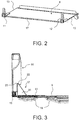
- At least one of the shelves 8 is provided with a front flap 10.
- the flap 10 is fastened to the shelf 8 by means of two flap fastening devices 11, 12.
- the shelf 8 with the two flap fastening devices 11, 12 is in the Fig. 2 shown in a perspective view and the FIG. 3 shows a side view of the shelf 8 with flap 10.
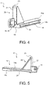
- Die FIGS. 4 and 5 show one of the flap fasteners 11 in perspective views.
- the shelves 8 are mounted for example by means of the inner container 2 tightened ribs 16.
- the shelf 8 is formed as a substantially flat plate or shelf, in particular made of glass.
- the shelf 8 can also be made of another material, e.g. Plastic, be made.
- the shelf 8 is rectangular and includes side edges 13th
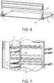
- the flap 10 is provided in a in the Figures 3 and 6 shown first position to be folded upwards, so as to close the upwardly directed, designed as a bearing surface surface of the shelf 8 to the front. In one in the Fig. 7 shown second position, the flap 10 is folded down to make the storage area of the shelf 8 accessible.
- the flap fastening devices 11, 12 are each produced in one piece from plastic, in particular by injection molding. They are attached to the side edges 13 of the shelf 8.
- the fastening device 14 is formed U-shaped and comprises a top wall 14 a, a bottom wall 14 b and a rear wall 14 c, which thereby form a groove, the width of the thickness of the shelf 8 is adapted such that the plugged onto the side edges 13 Flap fastening devices 11, 12 stuck on the side edges 13 frictionally.
- the upper wall 14a When plugged in thus the upper wall 14a is located on the upwardly directed, designed as a storage area for frozen or Kältegut storage surface of the shelf 8 and the lower wall 14b on the downwardly facing surface of the shelf 8 at.
- the rear wall 14 c of the fastening device 14 abuts against the corresponding side edge 13 of the shelf 8.
- the fastening device 14 is closed to the front with a wall 15.
- the flap 10 is pivotally mounted by means of the flap fastening devices 11, 12 with respect to a horizontal axis 17.
- the flap fastening devices 11, 12 each comprise a mounting device 18 integrally formed on the fastening device 14, in particular in the form of a pin 19.
- the pins 19 engage in openings or depressions of the flap 10 and are arranged such that, when the flap fastening devices 11, 12 are attached to the side edges 13 of the shelf 8, facing each other.
- the axis 17, with respect to which the flap 10 is pivotally mounted, passes through the pin 19th
- the flap fastening devices 11, 12 comprise a stop 20 integrally formed on the fastening device 14 with a flat wall 21.
- the wall 21 of the stop 20 is directed forward and upwardly with respect to the fastening device 14.
- the wall 21 of the stopper 20 is provided to limit pivotal movement of the flap 10 upwardly relative to the shelf 8 such that the flap 10 is oriented at right angles to the bearing surface of the shelf 8 in its first, upwardly folded position.
- the stopper 20 thus represents an upper stop for the flap 10.
- the flap 10 has a laterally arranged undercut 22 which engages with the upper edge 23 of the stopper 20 when the flap 10 is in its first position, ie in its raised position, to the flap 10 in this To hold position or to fix.
- the flap 10 is in its second position, ie in its folded down position, then limited in the case of the present embodiment, the wall 15 of the fastening device 14, the folding movement of the flap 10 down.
- the wall 15 of the fastening device 14 thus represents a lower stop for the flap 10.
- the flap 10 In its second position, in particular the flap 10 is oriented such that it is also possible to close the corresponding door leaf 5, 6.
- the fastening device 14 is provided with a recess 24.
- the recess 24 is e.g. formed half-moon-shaped or semicircular.
- the recess 24 is formed in the lower wall 14b of the fastening device 14 and is intended to cooperate with a recess 25 formed on one of the ribs 16.
- the bulge 25 is formed corresponding to the recess 24 and supports at least one positionally accurate attachment of the flap fastening device 11, 12 on the shelf 8, when it is fixed in the freezer compartment 3 or in the refrigerator 4.
- FIGS. 8 and 9 show a further flap fastener 31, which instead of in the FIGS. 2 to 7 shown flap fastener 11 can be used for the flap 10.
- components of the FIGS. 8 and 9 shown flap fastener 31, which are substantially identical in construction and function with components of the flap fastener 11, provided with the same reference numerals.
- the flap fastening device 31 is also made in one piece from plastic, in particular by injection molding and is attached to the side edge 13 of the shelf 8.
- the flap fastening device 31 differs substantially from the flap fastening devices 11, 12 in its fastening device 32, by means of which the flap fastening device 31 is fastened to the shelf 10.
- the fastening device 32 by means of which the flap fastening device 31 is placed on the side edge 13 of the shelf 8, is U-shaped and comprises in each case a top wall, a bottom wall 32 b and a rear wall 32 c, which thereby a groove form, the width of the thickness of the shelf 8 is adapted such that the plugged onto the side edges 13 flap fastening device 31 stuck on the side edges 13 frictionally.
- the upper wall When plugged in, the upper wall thus abuts the upwardly directed surface of the shelf 8 and the lower wall 32 b, which is designed as a storage area for freezer or refrigerated goods, on the downwardly directed surface of the shelf 8.
- the rear wall 32 c of the fastening device 31 abuts against the corresponding side edge 13 of the shelf 8.
- the fastening device 32 and the lower wall 32 c is provided with a biased, downwardly directed latching tongue 33 which in the installed state of the provided with the flap fastening device 31 shelf 8 with the inner container 2 of the household refrigerator 1 with a recess 34 a the ribs 16 locked. Due to the locking, a positionally accurate fastening of the flap fastening device 31 on the shelf 8, if it is fixed in the freezer compartment 3 or in the refrigerator compartment 4, is at least supported.
Description
Die Erfindung betrifft eine Ablagevorrichtung und ein Haushaltskältegerät mit einem Fachboden.The invention relates to a storage device and a household refrigerator with a shelf.
Die
Aufgabe der vorliegenden Erfindung ist es, eine verbesserte Ablagevorrichtung anzugeben.Object of the present invention is to provide an improved storage device.
Die Aufgabe der Erfindung wird gelöst durch eine Ablagevorrichtung, aufweisend eine ebene, insbesondere rechteckige und Seitenkanten aufweisende Ablageplatte, eine Klappenbefestigungsvorrichtung zum schwenkbaren Lagern einer Klappe an der ebenen, insbesondere rechteckigen und Seitenkanten aufweisenden Ablageplatte, wobei die Klappenbefestigungsvorrichtung einstückig ausgeführt ist und eine Befestigungsvorrichtung mit der die Klappenbefestigungsvorrichtung auf die Seitenkante der Ablageplatte aufgesteckt ist, und eine Lagerungsvorrichtung aufweist, mittels derer die Klappe relativ zur Ablageplatte schwenkbar gelagert ist, und eine mittels der Klappenbefestigungsvorrichtung relativ zur Ablageplatte schwenkbar gelagerte Klappe, wobei die Klappenbefestigungsvorrichtung ein an der Ablageplatte montiertes Zusatzteil ist, und wobei die Befestigungsvorrichtung U-förmig ausgebildet ist und eine obere Wand, eine untere Wand und eine hintere Wand aufweist, welche eine Nut bilden, deren Breite der Dicke der Ablageplatte derart angepasst ist, dass die auf die Seitenkanten aufgesteckte Klappenbefestigungsvorrichtung kraftschlüssig auf der Seitenkante steckt.The object of the invention is achieved by a storage device comprising a flat, in particular rectangular and side edges having shelf, a flap fastening device for pivotally supporting a flap on the flat, in particular rectangular and side edges having shelf, wherein the flap fastening device is made in one piece and a fastening device with the the flap fastening device is mounted on the side edge of the tray, and has a storage device by means of which the flap is pivotally mounted relative to the tray and a flap pivotally mounted by the flap fastener relative to the tray, the flap fastener being an attachment mounted to the tray, and in which the fastening device is U-shaped and has an upper wall, a lower wall and a rear wall, which form a groove whose width is adapted to the thickness of the tray so that the plugged onto the side edges flap fastening device stuck on the side edge.
Ein weiterer Aspekt der Erfindung betrifft ein Haushaltskältegerät, aufweisend einen Innenbehälter mit einem kühlbaren Innenraum, eine zum Kühlen des Innenraums vorgesehene Kältevorrichtung, die insbesondere als Kältemittelkreislauf ausgeführt ist, ein zum Öffnen und Schließen des Innenraums vorgesehenes Türblatt, und eine innerhalb des Innenraums angeordnete erfindungsgemäße Ablagevorrichtung, wobei die Ablageplatte der Ablagevorrichtung als ein am Innenbehälter angeordneter Fachboden ausgebildet ist. Das erfindungsgemäße Haushaltskältegerät ist beispielsweise ein Haushaltskühlgerät, ein Haushaltskältegerät oder eine Kühl- /Gefrierkombination. Das zum Öffnen und Schließen des kühlbaren Innenraums vorgesehene Türblatt ist vorzugsweise bezüglich einer vertikal verlaufenden Achse relativ zum Innenbehälter schwenkbar gelagert.Another aspect of the invention relates to a household refrigerating appliance, comprising an inner container with a coolable interior, a cooling device provided for cooling the interior, which is designed in particular as a refrigerant circuit, a door opening provided for opening and closing the interior, and a storage device according to the invention arranged inside the interior , wherein the storage plate of the storage device is designed as a arranged on the inner container shelf. The domestic refrigerator according to the invention is for example a household refrigerator, a household refrigerator or a fridge freezer. That to open and close the door provided with the coolable interior is preferably pivotably mounted relative to the inner container with respect to a vertical axis.
Die erfindungsgemäße einstückig ausgeführte Klappenbefestigungsvorrichtung, die vorzugsweise aus Kunststoff im Spritzgussverfahren gefertigt ist, ist demnach vorgesehen, eine Klappe schwenkbar relativ zur Ablageplatte zu lagern. Erfindungsgemäß kann dazu die Klappenbefestigungsvorrichtung auf die Seitenkante der Ablageplatte gesteckt werden, wodurch es möglich ist, nachträglich die Ablageplatte mit der schwenkbaren Klappe zu versehen, also auch nachträglich eine ebene, rechteckige und Seitenkanten aufweisende Ablageplatte mit der Klappe und der Klappenbefestigungsvorrichtung zu versehen, um die erfindungsgemäße Ablagevorrichtung zu erhalten. Die Ablageplatte ist z.B. aus Glas gefertigt. Andere Materialien sind aber auch möglich. Für das schwenkbare Lagern der Klappe umfasst die erfindungsgemäße Klappenbefestigungsvorrichtung die Lagerungsvorrichtung.The invention integrally executed flap fastening device, which is preferably made of plastic by injection molding, is therefore provided to pivotally support a flap relative to the tray. According to the invention, the flap attachment device can be plugged onto the side edge of the tray, making it possible to subsequently provide the tray with the hinged flap, so also subsequently a flat, rectangular and side edges having tray with the flap and the flap fastening device to provide the To obtain inventive storage device. The tray is e.g. made of glass. Other materials are also possible. For pivotally supporting the flap, the flap fastening device according to the invention comprises the storage device.
Besonderes vorteilhaft ist die erfindungsgemäße Klappenbefestigungsvorrichtung bei einer Verwendung für ein Haushaltskältegerät. In diesem Fall stellt die Ablageplatte einen Fachboden dar, der innerhalb des kühlbaren Innenraums des Haushaltskältegerätes angeordnet ist. In diesem Fall bietet das erfindungsgemäße Haushaltskältegerät ein verbessertes Haushaltskältegerät mit einem Fachboden, der mit einer Klappe versehen ist.Particularly advantageous is the flap fastening device according to the invention when used for a household refrigerator. In this case, the shelf represents a shelf, which is located within the coolable interior of the household refrigerator. In this case, the household refrigerator according to the invention provides an improved domestic refrigerator with a shelf, which is provided with a flap.
Um die Klappe relativ einfach schwenkbar zu lagern, ist nach einer bevorzugten Ausführungsform der erfindungsgemäßen Klappenbefestigungsvorrichtung deren Lagerungsvorrichtung als ein Zapfen ausgebildet, welcher vorgesehen ist, in eine Öffnung oder eine Einbuchtung der Klappe einzugreifen. Vorzugsweise umfasst die erfindungsgemäße Ablagevorrichtung zwei erfindungsgemäße Klappenbefestigungsvorrichtungen, von denen eine auf die linke und die andere auf die rechte Seitenkante der Ablageplatte gesteckt ist, d.h. auf beiden Seitenkanten der Ablageplatte sind jeweils eine erfindungsgemäße Klappenbefestigungsvorrichtung gesteckt, welche vorzugsweise spiegelverkehrt ausgeführt sind, sodass deren Zapfen zueinender gewandt sind, so dass eine Achse, bezüglich derer die Klappe schwenkbar gelagert ist, durch die Zapfen verläuft. Somit ist es möglich, die Klappe relativ einfach in die Zapfen einzuhängen.In order to store the flap relatively easily pivotable, according to a preferred embodiment of the flap fastening device according to the invention, its storage device is designed as a pin which is intended to engage in an opening or a recess of the flap. Preferably, the storage device according to the invention comprises two flap fastening devices according to the invention, one of which is placed on the left and the other on the right side edge of the shelf, ie on both side edges of the shelf plate respectively a flap fastening device according to the invention are inserted, which are preferably mirror-inverted, so that their pin zueinender are turned so that an axis, with respect to which the flap is pivotally mounted, passes through the pins. Thus, it is possible to easily hang the flap in the pin.
Um die erfindungsgemäße Klappenbefestigungsvorrichtung relativ einfach auf die Ablageplatte stecken zu können, ist deren Befestigungsvorrichtung U-förmig ausgebildet und weist eine obere Wand, eine untere Wand und eine hintere Wand auf, welche eine Nut bilden. Für einen relativ guten Halt an der Ablageplatte ist es vorgesehen, dass die Breite der Nut der Dicke der Ablageplatte derart angepasst ist, dass die auf die Seitenkanten aufgesteckte Klappenbefestigungsvorrichtung kraftschlüssig auf der Seitenkante steckt.In order to put the flap fastening device according to the invention relatively easily on the shelf, whose attachment device is U-shaped and has an upper wall, a lower wall and a rear wall, which form a groove. For a relatively good hold on the tray, it is provided that the width of the groove of the thickness of the tray is adjusted so that the plugged onto the side edges flap fastening device stuck on the side edge.
Um eine Schwenkbewegung der Klappe nach unten zu begrenzen, kann die U-förmig ausgebildete Befestigungsvorrichtung eine vordere Wand aufweisen, deren nach außen gerichtete Seite als unterer Anschlag dient, welcher eine Schwenkbewegung der Klappe nach unten relativ zur Ablageplatte begrenzt.In order to limit a pivoting movement of the flap down, the U-shaped fastening device may have a front wall whose outwardly directed side serves as a lower stop, which limits pivotal movement of the flap down relative to the tray.
Gemäß einer Variante weist die Klappenbefestigungsvorrichtung einen oberen Anschlag auf, welcher vorgesehen ist, eine Schwenkbewegung der Klappe nach oben relativ zur Ablageplatte derart zu begrenzen, dass die Klappe in einer hochgeklappten Stellung rechtwinklig zur Ablageplatte ausgerichtet ist. Dadurch schließt die hochgeklappte Klappe insbesondere bei der Verwendung im Haushaltskältegerät die Ablageplatte bzw. den Fachboden frontseitig und es wird verhindert, dass die Klappe auf die nach oben gerichtete Fläche der Ablageplatte bzw. des Fachbodens klappt.According to a variant, the flap fastening device has an upper stop which is provided to limit a pivoting movement of the flap upwards relative to the placement plate in such a way that the flap is oriented at right angles to the placement plate in a folded-up position. As a result, the folded flap closes the shelf or the shelf at the front, especially when used in household refrigeration appliance and it is prevented that the flap works on the upwardly directed surface of the shelf or the shelf.
Der obere Anschlag der Klappenbefestigungsvorrichtung kann beispielsweise eine ebenen Wand aufweisen, welche nach vorne gerichtet und nach oben bezüglich der Befestigungsvorrichtung ausgerichtet und vorgesehen ist, die Schwenkbewegung der Klappe nach oben relativ zur Ablageplatte zu begrenzen. Die ebene Wand bietet einen relativ großflächigen Anschlag für die Klappe.For example, the top stop of the flap fastener may have a flat wall which is directed forwardly and upwardly with respect to the fastener and intended to limit pivotal movement of the flap upwardly relative to the shelf. The flat wall provides a relatively large-scale stop for the flap.
Um die hochgeklappte Klappe in dieser Stellung zu fixieren, kann nach einer Ausführungsform der erfindungsgemäßen Ablagevorrichtung die Klappenbefestigungsvorrichtung einen nach oben abstehenden Steg aufweisen, mit dessen Oberkante ein Hinterschnitt der Klappe in ihrer hochgeklappten Stellung verrastet. Dadurch wird zumindest die Gefahr eines unbeabsichtigtes nach unten Schwenkens der Klappe verringert.In order to fix the folded-up flap in this position, according to one embodiment of the depositing device according to the invention, the flap fastening device can have an upwardly projecting web, with the upper edge of which an undercut of the flap locks in its raised position. As a result, at least the risk of unintentional downward pivoting of the flap is reduced.
Der Steg kann vorzugsweise als der obere Anschlag ausgebildet sein, sodass die Oberkante, mit der der Hinterschnitt der Klappe in der hochgeklappten Stellung verrastet, die Oberkante des oberen Anschlags ist.The web may preferably be formed as the upper stop, so that the upper edge, with which the undercut of the flap locked in the folded-up position, the upper edge of the upper stop.
Nach einer bevorzugten Ausführungsform des erfindungsgemäßen Haushaltskältegerätes umfasst die Befestigungsvorrichtung der Klappenbefestigungsvorrichtung Fixiermittel, welche mit Gegenfixiermittel für ein Fixieren der Klappenbefestigungsvorrichtung innerhalb des Innenraums zusammenwirken. Die Fixiermittel sind insbesondere an der in Richtung Innenraum gerichteten Seite des Innenbehälters angezogen. Aufgrund der Fixiermittel ist die Klappenbefestigungsvorrichtung am Fachboden und im kühlbaren Innenraum fixiert, wodurch z.B. eine Gefahr eines Verklemmens der Klappe verringert wird.According to a preferred embodiment of the household refrigerating appliance according to the invention, the fastening device of the flap fastening device comprises fixing means, which cooperate with counter-fixing means for fixing the flap fastening device inside the interior. The fixing means are attracted in particular to the direction of the interior side of the inner container. Due to the fixing means, the flap fastening device is fixed to the shelf and in the coolable interior, whereby e.g. a risk of jamming the flap is reduced.
An der in Richtung Innenraum gerichteten Seite des Innenbehälters des erfindungsgemäßen Haushaltskältegerätes können Vorsprünge angezogen sein, mittels derer der Fachboden gelagert und/oder befestigt ist. Die Vorsprünge sind insbesondre als Rippen ausgebildet, auf denen z.B. der Fachboden aufliegt. Vorzugsweise umfasst einer dieser Vorsprünge die Gegenfixiermittel. Dadurch können die Gegenfixiermittel mit relativ geringem Aufwand realisiert werden.On the directed towards the interior side of the inner container of the household refrigerator according to the invention projections may be tightened by means of which the shelf is stored and / or fixed. The projections are in particular formed as ribs on which e.g. the shelf rests. Preferably, one of these projections comprises the counter-fixing means. This allows the Gegenfixiermittel be realized with relatively little effort.
Die Fixiermittel können beispielsweise als eine Aussparung in der unteren Wand der Befestigungsvorrichtung der Klappenbefestigungsvorrichtung und die Gegenfixiervorrichtung als eine mit der Aussparung zusammen wirkende Ausbuchtung ausgebildet sein. Die Ausbuchtung kann vorzugsweise an eine der Rippen angeformt sein. Dadurch wird die Klappenbefestigungsvorrichtung automatisch beim Einsetzen des Fachbodens in den Innenraum des Haushaltskältegerätes fixiert, wodurch automatisch eine positionsgenaue Ausrichtung der Klappenbefestigungsvorrichtung erreicht wird.The fixing means may be formed, for example, as a recess in the lower wall of the fastening device of the flap fastening device and the counter-fixing device as a recess cooperating with the recess. The bulge may preferably be formed on one of the ribs. As a result, the flap fastening device is automatically fixed when inserting the shelf into the interior of the household refrigerator, whereby automatically a positionally accurate alignment of the flap fastening device is achieved.
Die Fixiermittel können z.B. auch als eine in der unteren Wand der U-förmig ausgebildeten Befestigungsvorrichtung ausgebildete Rastvorrichtung und die Gegenfixiermittel als eine mit der Rastvorrichtung zusammen wirkende Gegenrastvorrichtung ausgebildet sein, welche insbesondere an eine der Rippen ausgebildet ist. Auch dadurch wird es ermöglicht, dass die Klappenbefestigungsvorrichtung automatisch beim Einsetzen des Fachbodens in den Innenraum des Haushaltskältegerätes fixiert wird, wodurch automatisch eine positionsgenaue Ausrichtung der Klappenbefestigungsvorrichtung erreicht wird.The fixing means can also be designed, for example, as a latching device formed in the lower wall of the U-shaped fastening device and the counterfixing means as a counter-latching device cooperating with the latching device, which latching device is in particular formed on one of the ribs. This also makes it possible that the flap fastening device is automatically fixed when inserting the shelf in the interior of the household refrigerator, thereby automatically a positionally accurate alignment of the flap fastening device is achieved.
Die Rastvorrichtung kann vorzugsweise als eine nach unten geneigte Rastzunge und die Gegenrastvorrichtung als eine Einbuchtung in einer der Rippen ausgebildet sein.The latching device may preferably be formed as a downwardly inclined latching tongue and the counter-latching device as a recess in one of the ribs.
Je nach Ausführungsform bietet die Erfindung somit eine Klappenbefestigung auf einer insbesondere als Glasplatte ausgebildeten Ablageplatte. In Verbindung mit dem Haushaltskältegerät kann somit auf eine relativ komplizierte Lagerung der Klappe am Innenbehälter verzichtet werden.Depending on the embodiment, the invention thus provides a flap attachment to a particular designed as a glass plate shelf. In conjunction with the household refrigerator can thus be dispensed with a relatively complicated storage of the flap on the inner container.
Aufgrund der erfindungsgemäßen Klappenbefestigungsvorrichtung kann z.B. über ein zusätzliche auf den beispielsweise als Glasplatte ausgebildeten Fachboden insbesondere links und rechts montiertes Zusatzteil, d.h. die Klappenbefestigungsvorrichtung ein Lagerfach über die Klappe abgetrennt werden.Due to the flap fastening device according to the invention, e.g. via an additional on the example formed as a glass plate shelf especially left and right mounted additional part, i. the flap attachment device a storage compartment can be separated via the flap.
Die Klappenlagerung bzw. Klappenbefestigungsvorrichtung kann je nach Ausführungsform die Lagerung der Klappe, einen Anschlag der Klappe nach oben und/oder unten, und/oder eine Rastfunktion der Klappe in der offenen bzw. geschlossenen Position bieten. Ausführungsbeispiele der Erfindung sind exemplarisch in den beigefügten schematischen Zeichnungen dargestellt. Es zeigen:
- Fig. 1
- ein Haushaltskältegerät mit einem kühlbaren Innenraum, in dem wenigstens ein Fachboden mit einer Klappe angeordnet ist,
- Fig. 2
- einer der Fachböden mit Klappenbefestigungsvorrichtungen in einer perspektivischen Darstellung,
- Fig. 3
- den Fachboden mit Klappe in einer Seitenansicht.
Figuren - perspektivische Darstellungen einer der Klappenbefestigungsvorrichtungen,
- Fig. 6
- den Fachboden mit Klappe,
- Fig. 7
- einen Ausschnitt des kühlbaren Innenraums des Haushaltskältegerätes im Bereich des Fachbodens mit Klappe,
- Fig. 8
- eine alternative Klappenbefestigungsvorrichtung in einer perspektivischen Darstellung und
- Fig. 9
- eine Seitenansicht des im kühlbaren Innenraum des Haushaltskältegerätes angeordneten Fachbodens mit Klappe.
- Fig. 1
- a domestic refrigerator with a coolable interior, in which at least one shelf is arranged with a flap,
- Fig. 2
- one of the shelves with flap fasteners in a perspective view,
- Fig. 3
- the shelf with flap in a side view.
- FIGS. 4, 5
- perspective views of one of the flap fastening devices,
- Fig. 6
- the shelf with flap,
- Fig. 7
- a section of the coolable interior of the household refrigerator in the area of the shelf with flap,
- Fig. 8
- an alternative flap fastening device in a perspective view and
- Fig. 9
- a side view of the arranged in the coolable interior of the household refrigerator shelf with flap.
Die
Das Haushaltskältegerät 1 umfasst wenigstens einen Kältemittelkreislauf zum Kühlen des Gefrierraums 3 und des Kühlraums 4. Für den Kühlraum 4 und den Gefrierraum 3 kann ein gemeinsamer Kältemittelkreislauf vorgesehen sein, der z.B. einen zum Kühlen des Kühlraums 4 vorgesehenen Verdampfer und einen zum Kühlen des Gefrierraums 3 vorgesehenen Verdampfer umfasst. Das Haushaltskältegerät 1 kann aber auch getrennte Kältemittelkreisläufe für den Gefrierraum 3 und den Kühlraum 4 aufweisen.The domestic refrigerator 1 comprises at least one refrigerant circuit for cooling the
Das Haushaltskältegerät 1 weist im Falle des vorliegenden Ausführungsbeispiels zwei Türblätter 5, 6 zum Verschließen des Gefrierraums 3 bzw. des Kühlraums 4 auf. Bei geöffneten Türblättern 5, 6 sind der Gefrierraum 3 und der Kühlraum 4 zugänglich. An der in Richtung Kühlraum 4 gerichteten Seite des zum Verschließen des Kühlraums 4 vorgesehenen Türblatts 6 sind im Falle des vorliegenden Ausführungsbeispiels mehrere Türabsteller 7 zum Lagern von Kühlgut angeordnet.The household refrigerator 1, in the case of the present embodiment, two door leaves 5, 6 for closing the
Im Gefrierraum 3 ist beispielsweise wenigstens ein Fachboden 8 zum Lagern von Gefriergut und im Kühlraum 4 sind mehrere Fachböden 8 zum Lagern von Kühlgut angeordnet. Im unteren Bereich des Kühlraums 4 ist insbesondere eine Schublade 9 angeordnet, in der Kühlgut gelagert werden kann.In the
Das Haushaltskältegerät 1 weist ferner eine nicht näher dargestellte Steuervorrichtung auf, die eingerichtet ist, den oder die Kältemittelkreisläufe im Betrieb des Haushaltskältegerätes 1 derart anzusteuern, dass der Gefrierraum 3 und der Kühlraum 4 zumindest in etwa vorgegebene oder einstellbare Soll-Temperaturen aufweisen, wie dies dem Fachmann im Prinzip bekannt ist.The household refrigerator 1 further comprises a control device, not shown, which is adapted to control the or the refrigerant circuits during operation of the household refrigerator 1 such that the
Im Falle des vorliegenden Ausführungsbeispiels ist wenigstens einer der Fachböden 8 mit einer frontseitigen Klappe 10 versehen. Die Klappe 10 ist mittels zweier Klappenbefestigungsvorrichtungen 11, 12 am Fachboden 8 befestigt. Der Fachboden 8 mit den beiden Klappenbefestigungsvorrichtungen 11, 12 ist in der
Im Falle des vorliegenden Ausführungsbeispiels ist der Fachboden 8 als eine im Wesentlichen plane Platte bzw. Ablageplatte insbesondere aus Glas ausgebildet. Der Fachboden 8 kann auch aus einem anderen Material, z.B. Kunststoff, gefertigt sein. Der Fachboden 8 ist rechteckig ausgeführt und umfasst Seitenkanten 13.In the case of the present embodiment, the
Die Klappe 10 ist vorgesehen, in einer in den
Im Falle des vorliegenden Ausführungsbeispiels sind die Klappenbefestigungsvorrichtungen 11, 12 jeweils einstückig aus Kunststoff insbesondere im Spritzgussverfahren hergestellt. Sie sind auf die Seitenkanten 13 des Fachbodens 8 aufgesteckt. Dazu umfassen sie jeweils eine Befestigungsvorrichtung 14, mittels derer die Klappenbefestigungsvorrichtungen 11, 12 auf die Seitenkanten 13 gesteckt sind. Die Befestigungsvorrichtung 14 ist U-förmig ausgebildet und umfasst eine obere Wand 14a, eine untere Wand 14b und eine hintere Wand 14c, welche dadurch eine Nut bilden, deren Breite der Dicke des Fachbodens 8 derart angepasst ist, dass die auf die Seitenkanten 13 aufgesteckten Klappenbefestigungsvorrichtungen 11, 12 kraftschlüssig auf den Seitenkanten 13 stecken. Im aufgesteckten Zustand liegt somit die obere Wand 14a an der nach oben gerichteten, als Lagerfläche für Gefrier- oder Kältegut ausgebildeten Lagerfläche des Fachbodens 8 und die untere Wand 14b an der nach unten gerichteten Fläche des Fachbodens 8 an. Die hintere Wand 14c der Befestigungsvorrichtung 14 liegt an der entsprechenden Seitenkante 13 des Fachbodens 8 an.In the case of the present exemplary embodiment, the
Um die Klappenbefestigungsvorrichtungen 11, 12 möglichst passgenau bzw. positionsgenau an die Seitenkanten 13 des Fachbodens 8 im Bereich der vorderen Ecken des Fachbodens 8 zu stecken, ist die Befestigungsvorrichtung 14 nach vorne mit einer Wand 15 abgeschlossen.In order to fit the
Die Klappe 10 ist mittels der Klappenbefestigungsvorrichtungen 11, 12 schwenkbar bezüglich einer horizontal verlaufenden Achse 17 gelagert. Dazu umfassen die Klappenbefestigungsvorrichtungen 11, 12 jeweils eine an der Befestigungsvorrichtung 14 einstückig angeformte Lagerungsvorrichtung 18 insbesondere in Form eines Zapfens 19. Die Zapfen 19 greifen in Öffnungen oder Vertiefungen der Klappe 10 ein und sind derart angeordnet, dass sie, wenn die Klappenbefestigungsvorrichtungen 11, 12 auf den Seitenkanten 13 des Fachbodens 8 aufgesteckt sind, zueinander zugewandt sind. Die Achse 17, bezügliche derer die Klappe 10 schwenkbar gelagert ist, verläuft durch die Zapfen 19.The
Im Falle des vorliegenden Ausführungsbeispiels umfassen die Klappenbefestigungsvorrichtungen 11, 12 einen an der Befestigungsvorrichtung 14 einstückig angeformeten Anschlag 20 mit einer ebenen Wand 21. Die Wand 21 des Anschlags 20 ist nach vorne gerichtet und nach oben bezüglich der Befestigungsvorrichtung 14 ausgerichtet. Die Wand 21 des Anschlags 20 ist vorgesehen, eine Schwenkbewegung der Klappe 10 nach oben relativ zum Fachboden 8 derart zu begrenzen, dass die Klappe 10 in ihrer ersten, hochgeklappten Stellung rechtwinklig zur Lagerfläche des Fachbodens 8 ausgerichtet ist. Der Anschlag 20 stellt somit einen oberen Anschlag für die Klappe 10 dar.In the case of the present embodiment, the
Im Falle des vorliegenden Ausführungsbeispiels weist die Klappe 10 einen seitlich angeordneten Hinterschnitt 22 auf, der mit der Oberkante 23 des Anschlags 20 verrastet, wenn sich die Klappe 10 in ihrer ersten Stellung, also in ihrer hochgeklappten Stellung, befindet, um die Klappe 10 in dieser Stellung zu halten bzw. zu fixieren.In the case of the present embodiment, the
Befindet sich die Klappe 10 in ihrer zweiten Stellung, also in ihrer herunter geklappten Stellung, dann begrenzt im Falle des vorliegenden Ausführungsbeispiels die Wand 15 der Befestigungsvorrichtung 14 die Klappbewegung der Klappe 10 nach unten. Die Wand 15 der Befestigungsvorrichtung 14 stellt somit einen unteren Anschlag für die Klappe 10 dar. In ihrer zweiten Stellung ist insbesondere die Klappe 10 derart ausgerichtet, dass es auch möglich ist, das entsprechende Türblatt 5, 6 zu schließen.The
Im Falle des vorliegenden Ausführungsbeispiels ist die Befestigungsvorrichtung 14 mit einer Aussparung 24 versehen. Die Aussparung 24 ist z.B. halbmondförmig bzw. halbkreisförmig ausgebildet. Die Aussparung 24 ist in der unteren Wand 14b der Befestigungsvorrichtung 14 ausgebildet und ist vorgesehen, mit einer an einer der Rippen 16 angeformten Ausbuchtung 25 zusammen zu wirken. Die Ausbuchtung 25 ist entsprechend der Aussparung 24 ausgebildet und unterstützt zumindest eine positionsgenaue Befestigung der Klappenbefestigungsvorrichtung 11, 12 am Fachboden 8, wenn dieser im Gefrierraum 3 bzw. im Kühlraum 4 befestigt ist.In the case of the present embodiment, the
Die
Im Falle des vorliegenden Ausführungsbeispiels ist die Klappenbefestigungsvorrichtung 31 ebenfalls einstückig aus Kunststoff insbesondere im Spritzgussverfahren hergestellt und ist auf die Seitenkante 13 des Fachbodens 8 aufgesteckt.In the case of the present embodiment, the
Die Klappenbefestigungsvorrichtung 31 unterscheidet sich im Wesentlichen von den Klappenbefestigungsvorrichtungen 11, 12 in ihrer Befestigungsvorrichtung 32, mittels derer die Klappenbefestigungsvorrichtung 31 am Fachboden 10 befestigt ist. Die Befestigungsvorrichtung 32, mittels derer die Klappenbefestigungsvorrichtung 31 auf die Seitenkante 13 des Fachbodens 8 gesteckt ist, ist U-förmig ausgebildet und umfasst jeweils eine obere Wand, eine untere Wand 32b und eine hintere Wand 32c, welche dadurch eine Nut bilden, deren Breite der Dicke des Fachbodens 8 derart angepasst ist, dass die auf die Seitenkanten 13 aufgesteckte Klappenbefestigungsvorrichtung 31 kraftschlüssig auf den Seitenkanten 13 steckt. Im aufgesteckten Zustand liegt somit die obere Wand an der nach oben gerichteten, als Lagerfläche für Gefrier- oder Kältegut ausgebildeten Fläche des Fachbodens 8 und die untere Wand 32b an der nach unten gerichteten Fläche des Fachbodens 8 an. Die hintere Wand 32c der Befestigungsvorrichtung 31 liegt an der entsprechenden Seitenkante 13 des Fachbodens 8 an.The
Im Falle des vorliegenden Ausführungsbeispiels ist die Befestigungsvorrichtung 32 bzw. deren untere Wand 32c mit einer vorgespannten, nach unten gerichteten Rastzunge 33 versehen, welche im eingebauten Zustand des mit der Klappenbefestigungsvorrichtung 31 versehenen Fachbodens 8 mit dem Innenbehälter 2 des Haushaltskältegeräts 1 mit einer Aussparung 34 einer der Rippen 16 verrastet. Aufgrund der Verrastung wird eine positionsgenaue Befestigung der Klappenbefestigungsvorrichtung 31 am Fachboden 8, wenn dieser im Gefrierraum 3 bzw. im Kühlraum 4 befestigt ist, zumindest unterstützt.In the case of the present embodiment, the
- 11
- HaushaltskältegerätHousehold refrigerator
- 22
- Innenbehälterinner container
- 33
- Gefrierraumfreezer
- 44
- Kühlraumrefrigerator
- 5, 65, 6
- Türblattdoor leaf
- 77
- Türabstellerdoor racks
- 99
- FachbodenFold bottom
- 1010
- Klappeflap
- 11, 1211, 12
- KlappenbefestigungsvorrichtungFlap fastening device
- 1313
- Seitenkanteside edge
- 1414
- Befestigungsvorrichtungfastening device
- 14a14a
- obere Wandupper wall
- 14b14b
- untere Wandbottom wall
- 14c14c
- hintere Wandrear wall
- 1515
- Wandwall
- 1616
- Rippenribs
- 1717
- Achseaxis
- 1818
- Lagerungsvorrichtungstorage device
- 1919
- Zapfenspigot
- 2020
- Anschlagattack
- 2121
- Wandwall
- 2222
- Hinterschnittundercut
- 2323
- Oberkantetop edge
- 2424
- Aussparungrecess
- 2525
- Ausbuchtungbulge
- 3131
- KlappenbefestigungsvorrichtungFlap fastening device
- 3232
- Befestigungsvorrichtungfastening device
- 32b32b
- untere Wandbottom wall
- 32c32c
- hintere Wandrear wall
- 3333
- Rastzungecatch tongue
- 3434
- Aussparungrecess
Claims (13)
- Storage device having
a flat, in particular rectangular, shelf (8) having side edges (13),
a flap fastening device (11, 12, 31) for pivotably mounting a flap (10) on the flat, in particular rectangular, shelf (8) having side edges (13), wherein the flap fastening device (11, 12, 31) is made in one piece and has a fastening device (14, 32), with which the flap fastening device (11, 12, 31) is snapped onto the side edge (13) of the shelf (8), and a mounting device (18), by means of which the flap (10) is pivotably mounted relative to the shelf (8), and
a flap (10) pivotably mounted relative to the shelf (8) by means of the flap fastening device (11, 12, 31), wherein the flap fastening device (11, 12, 31) is an attachment mounted on the shelf (8), characterised in that the fastening device (14, 32) is designed to be U-shaped and has an upper wall (14a), a lower wall (14b, 32b) and a rear wall (14c, 32c) which form a groove, the width of which is adapted to the thickness of the shelf (8), such that the flap fastening device (11, 12, 31) snapped onto the side edges (13) is fitted onto the side edge (13) by force-fit. - Storage device according to claim 1, characterised in that the mounting device (18) is designed as a pin (19) which is provided to engage in an opening or a recess of the flap (10).
- Storage device according to one of claims 1 or 2, characterised in that the flap fastening device (11, 12, 21) has an upper stop (20) which is provided to limit a pivoting movement of the flap (10) upwards relative to the shelf (8), such that the flap (10) is aligned at right angles to the shelf (8) in a folded-up position.
- Storage device according to claim 3, characterised in that the upper stop (20) of the flap fastening device (11, 12, 31) has a flat wall (21) which is aligned forwards and upwards relative to the fastening device (14, 32) and is provided to limit the pivoting movement of the flap (10) upwards relative to the shelf (8).
- Storage device according to one of claims 1 to 4, characterised in that the flap fastening device (11, 12, 31) has an upwardly projecting web (20), with the upper edge (23) of which an undercut (22) of the flap (10) latches in its folded-up position.
- Storage device according to claim 5, characterised in that the web is designed as the upper stop (20), so that the upper edge (23), with which the undercut (22) of the flap (10) latches in the folded-up position, is the upper edge (23) of the upper stop (20).
- Storage device according to one of claims 1 to 6, characterised in that the U-shaped fastening device (14) has a front wall (15), the outwardly aligned side of which serves as a lower stop, which limits a pivoting movement of the flap (10) downwards relative to the shelf (8).
- Household refrigeration device, having an inner container (2) with a coolable interior space (3, 4), a refrigeration device provided for cooling the interior space (3, 4), which is designed in particular as a refrigerant circuit, and a door leaf (5, 6) provided for opening and closing the interior space (3, 4), characterised by a storage device arranged within the interior space (3, 4) according to one of claims 1 to 7, wherein the shelf of the storage device is designed as a shelf (8) arranged on the inner container (2).
- Household refrigeration device according to claim 8, characterised in that the fastening device (14, 32) of the flap fastening device (11, 12, 31) comprises fixing means (24, 33) which interact with counter-fixing means (25, 34) for fixing the flap fastening device (11, 12 , 31) within the interior space (3, 4), and which are fastened in particular to the side of the inner container (2) aligned towards the interior space (3, 4).
- Household refrigeration device according to claim 8, characterised in that projections formed in particular as ribs (16) are fastened to the side of the inner container (2) aligned towards the interior space (3, 4), and by means of which the shelf (8) is mounted and/or fixed, wherein in particular one of the projections comprises counter-fixing means (25, 34).
- Household refrigeration device according to claim 9 or 10, characterised in that the fixing means are designed as a cut-out (24) in the lower wall (14b) of the fastening device (14) and the counter-fixing means are designed as a convexity (25) which interacts with the cut-out (24) and is in particular integrally moulded on one of the ribs (16).
- Household refrigeration device according to claim 9 or 10, characterised in that the fixing means are designed as a latching device formed in the lower wall (32b) of the fastening device (32) and the counter-fixing means are designed as a counter-latching device which interacts with the latching device and in particular is formed on one of the ribs (16).
- Household refrigeration device according to claim 12, characterised in that the latching device is designed as a downwardly inclined latching tongue (33) and the counter-latching device is designed as a recess (34) in one of the ribs (16).
Priority Applications (1)
| Application Number | Priority Date | Filing Date | Title |
|---|---|---|---|
| PL13150439T PL2618084T3 (en) | 2012-01-20 | 2013-01-08 | Storage device with a flap fastening device and domestic cooler appliance with such a storage device |
Applications Claiming Priority (1)
| Application Number | Priority Date | Filing Date | Title |
|---|---|---|---|
| DE102012200847A DE102012200847A1 (en) | 2012-01-20 | 2012-01-20 | Flap fastening device, storage device and household refrigeration device with a shelf |
Publications (3)
| Publication Number | Publication Date |
|---|---|
| EP2618084A2 EP2618084A2 (en) | 2013-07-24 |
| EP2618084A3 EP2618084A3 (en) | 2015-09-30 |
| EP2618084B1 true EP2618084B1 (en) | 2019-08-07 |
Family
ID=47594511
Family Applications (1)
| Application Number | Title | Priority Date | Filing Date |
|---|---|---|---|
| EP13150439.1A Active EP2618084B1 (en) | 2012-01-20 | 2013-01-08 | Storage device with a flap fastening device and domestic cooler appliance with such a storage device |
Country Status (3)
| Country | Link |
|---|---|
| EP (1) | EP2618084B1 (en) |
| DE (1) | DE102012200847A1 (en) |
| PL (1) | PL2618084T3 (en) |
Families Citing this family (2)
| Publication number | Priority date | Publication date | Assignee | Title |
|---|---|---|---|---|
| DE102015212614A1 (en) * | 2015-07-06 | 2017-01-12 | BSH Hausgeräte GmbH | Domestic refrigerator with a storage compartment front wall |
| CN112197495B (en) * | 2015-07-30 | 2023-09-15 | 博西华电器(江苏)有限公司 | Tray for refrigeration appliance and refrigeration appliance |
Family Cites Families (5)
| Publication number | Priority date | Publication date | Assignee | Title |
|---|---|---|---|---|
| US4225203A (en) | 1978-08-30 | 1980-09-30 | Goodrode Melvin H | Energy saving inner door device for a refrigeration appliance |
| JP4334401B2 (en) * | 2003-10-21 | 2009-09-30 | 三洋電機株式会社 | Cold storage |
| DE202006001833U1 (en) * | 2006-02-06 | 2006-04-20 | BSH Bosch und Siemens Hausgeräte GmbH | The refrigerator |
| DE102008043615A1 (en) * | 2008-11-10 | 2010-05-12 | BSH Bosch und Siemens Hausgeräte GmbH | Refrigerating appliance, in particular household refrigerating appliance |
| DE102008063390A1 (en) * | 2008-12-30 | 2010-07-01 | BSH Bosch und Siemens Hausgeräte GmbH | Refrigerating appliance with a shelf |
-
2012
- 2012-01-20 DE DE102012200847A patent/DE102012200847A1/en not_active Withdrawn
-
2013
- 2013-01-08 PL PL13150439T patent/PL2618084T3/en unknown
- 2013-01-08 EP EP13150439.1A patent/EP2618084B1/en active Active
Non-Patent Citations (1)
| Title |
|---|
| None * |
Also Published As
| Publication number | Publication date |
|---|---|
| PL2618084T3 (en) | 2020-02-28 |
| EP2618084A3 (en) | 2015-09-30 |
| DE102012200847A1 (en) | 2013-07-25 |
| EP2618084A2 (en) | 2013-07-24 |
Similar Documents
| Publication | Publication Date | Title |
|---|---|---|
| EP2561292B1 (en) | Door leaf, method for producing a door leaf and refrigeration device having a door leaf | |
| WO2012022653A2 (en) | Refrigerator with means for storing articles | |
| EP2499445A2 (en) | Refrigerator having a door rack and a floatingly supported catch device | |
| EP2932172B1 (en) | Household refrigeration device comprising a height-adjustable door shelf | |
| EP2618084B1 (en) | Storage device with a flap fastening device and domestic cooler appliance with such a storage device | |
| DE102016225086A1 (en) | Arrangement for a domestic refrigerator with a wire basket and household refrigeration appliance with such an arrangement | |
| EP2606296B1 (en) | A refrigerator with a mounting rail for a shelf | |
| EP3030853B1 (en) | Domestic refrigeration appliance with an inner case and removable guide rails for a tray arranged therein | |
| EP3081885B1 (en) | Household refrigeration device with a shelf | |
| EP3136027B1 (en) | Household cooler with a front wall for a compartment | |
| EP3798546B1 (en) | Food storage container with a specifically shaped flap of a ventilation device and domestic refrigerator | |
| EP2344819B3 (en) | Refrigerator, in particular a household refrigerator | |
| EP3163233B1 (en) | Domestic refrigerator | |
| EP2549211B1 (en) | Cooling device with pivoting cooled goods holder | |
| DE102012001374A1 (en) | Cooling and freezing apparatus i.e. refrigerator, has tray bottom and drawer provided at cooled inner space, where tray bottom and drawer are components of common component that is not firmly arranged in inner space | |
| DE102009028418A1 (en) | Refrigeration device i.e. household refrigeration apparatus, has moving arrangement comprising frame, box shaped container guided in frame on rails that are uniformly curved upwards, and rib comprising gap at front end | |
| DE102014223518A1 (en) | Household refrigerating appliance with a food receiving tray in a receiving space, which has a front wall made of glass | |
| EP2561293B1 (en) | Door leaf and refrigerator having a door leaf | |
| EP2276985A2 (en) | Refrigerating appliance comprising a door tray | |
| EP2929264B1 (en) | Refrigerator with pivoting drawer device | |
| DE102008029032A1 (en) | Cooling device e.g. refrigerator for e.g. fruit, has cool products tray adjustably mounted in inner container, and stopper attached to laminar carrying element and arranged over cool products tray | |
| EP2561291A2 (en) | Door leaf, process for producing a door leaf and refrigerator having a door leaf | |
| EP3869128A1 (en) | Food storage container with specific coupling of a lid with a ventilation device and method |
Legal Events
| Date | Code | Title | Description |
|---|---|---|---|
| PUAI | Public reference made under article 153(3) epc to a published international application that has entered the european phase |
Free format text: ORIGINAL CODE: 0009012 |
|
| AK | Designated contracting states |
Kind code of ref document: A2 Designated state(s): AL AT BE BG CH CY CZ DE DK EE ES FI FR GB GR HR HU IE IS IT LI LT LU LV MC MK MT NL NO PL PT RO RS SE SI SK SM TR |
|
| AX | Request for extension of the european patent |
Extension state: BA ME |
|
| RAP1 | Party data changed (applicant data changed or rights of an application transferred) |
Owner name: BSH HAUSGERAETE GMBH |
|
| PUAL | Search report despatched |
Free format text: ORIGINAL CODE: 0009013 |
|
| AK | Designated contracting states |
Kind code of ref document: A3 Designated state(s): AL AT BE BG CH CY CZ DE DK EE ES FI FR GB GR HR HU IE IS IT LI LT LU LV MC MK MT NL NO PL PT RO RS SE SI SK SM TR |
|
| AX | Request for extension of the european patent |
Extension state: BA ME |
|
| RIC1 | Information provided on ipc code assigned before grant |
Ipc: F25D 23/02 20060101ALI20150824BHEP Ipc: F25D 25/02 20060101AFI20150824BHEP |
|
| 17P | Request for examination filed |
Effective date: 20160330 |
|
| RBV | Designated contracting states (corrected) |
Designated state(s): AL AT BE BG CH CY CZ DE DK EE ES FI FR GB GR HR HU IE IS IT LI LT LU LV MC MK MT NL NO PL PT RO RS SE SI SK SM TR |
|
| STAA | Information on the status of an ep patent application or granted ep patent |
Free format text: STATUS: EXAMINATION IS IN PROGRESS |
|
| 17Q | First examination report despatched |
Effective date: 20170310 |
|
| GRAP | Despatch of communication of intention to grant a patent |
Free format text: ORIGINAL CODE: EPIDOSNIGR1 |
|
| STAA | Information on the status of an ep patent application or granted ep patent |
Free format text: STATUS: GRANT OF PATENT IS INTENDED |
|
| INTG | Intention to grant announced |
Effective date: 20190322 |
|
| GRAS | Grant fee paid |
Free format text: ORIGINAL CODE: EPIDOSNIGR3 |
|
| GRAA | (expected) grant |
Free format text: ORIGINAL CODE: 0009210 |
|
| STAA | Information on the status of an ep patent application or granted ep patent |
Free format text: STATUS: THE PATENT HAS BEEN GRANTED |
|
| AK | Designated contracting states |
Kind code of ref document: B1 Designated state(s): AL AT BE BG CH CY CZ DE DK EE ES FI FR GB GR HR HU IE IS IT LI LT LU LV MC MK MT NL NO PL PT RO RS SE SI SK SM TR |
|
| REG | Reference to a national code |
Ref country code: GB Ref legal event code: FG4D Free format text: NOT ENGLISH |
|
| REG | Reference to a national code |
Ref country code: CH Ref legal event code: EP Ref country code: AT Ref legal event code: REF Ref document number: 1164515 Country of ref document: AT Kind code of ref document: T Effective date: 20190815 |
|
| REG | Reference to a national code |
Ref country code: DE Ref legal event code: R096 Ref document number: 502013013293 Country of ref document: DE |
|
| REG | Reference to a national code |
Ref country code: IE Ref legal event code: FG4D Free format text: LANGUAGE OF EP DOCUMENT: GERMAN |
|
| REG | Reference to a national code |
Ref country code: NL Ref legal event code: MP Effective date: 20190807 |
|
| REG | Reference to a national code |
Ref country code: LT Ref legal event code: MG4D |
|
| PG25 | Lapsed in a contracting state [announced via postgrant information from national office to epo] |
Ref country code: NL Free format text: LAPSE BECAUSE OF FAILURE TO SUBMIT A TRANSLATION OF THE DESCRIPTION OR TO PAY THE FEE WITHIN THE PRESCRIBED TIME-LIMIT Effective date: 20190807 Ref country code: SE Free format text: LAPSE BECAUSE OF FAILURE TO SUBMIT A TRANSLATION OF THE DESCRIPTION OR TO PAY THE FEE WITHIN THE PRESCRIBED TIME-LIMIT Effective date: 20190807 Ref country code: BG Free format text: LAPSE BECAUSE OF FAILURE TO SUBMIT A TRANSLATION OF THE DESCRIPTION OR TO PAY THE FEE WITHIN THE PRESCRIBED TIME-LIMIT Effective date: 20191107 Ref country code: LT Free format text: LAPSE BECAUSE OF FAILURE TO SUBMIT A TRANSLATION OF THE DESCRIPTION OR TO PAY THE FEE WITHIN THE PRESCRIBED TIME-LIMIT Effective date: 20190807 Ref country code: NO Free format text: LAPSE BECAUSE OF FAILURE TO SUBMIT A TRANSLATION OF THE DESCRIPTION OR TO PAY THE FEE WITHIN THE PRESCRIBED TIME-LIMIT Effective date: 20191107 Ref country code: FI Free format text: LAPSE BECAUSE OF FAILURE TO SUBMIT A TRANSLATION OF THE DESCRIPTION OR TO PAY THE FEE WITHIN THE PRESCRIBED TIME-LIMIT Effective date: 20190807 Ref country code: PT Free format text: LAPSE BECAUSE OF FAILURE TO SUBMIT A TRANSLATION OF THE DESCRIPTION OR TO PAY THE FEE WITHIN THE PRESCRIBED TIME-LIMIT Effective date: 20191209 Ref country code: HR Free format text: LAPSE BECAUSE OF FAILURE TO SUBMIT A TRANSLATION OF THE DESCRIPTION OR TO PAY THE FEE WITHIN THE PRESCRIBED TIME-LIMIT Effective date: 20190807 |
|
| PG25 | Lapsed in a contracting state [announced via postgrant information from national office to epo] |
Ref country code: LV Free format text: LAPSE BECAUSE OF FAILURE TO SUBMIT A TRANSLATION OF THE DESCRIPTION OR TO PAY THE FEE WITHIN THE PRESCRIBED TIME-LIMIT Effective date: 20190807 Ref country code: AL Free format text: LAPSE BECAUSE OF FAILURE TO SUBMIT A TRANSLATION OF THE DESCRIPTION OR TO PAY THE FEE WITHIN THE PRESCRIBED TIME-LIMIT Effective date: 20190807 Ref country code: GR Free format text: LAPSE BECAUSE OF FAILURE TO SUBMIT A TRANSLATION OF THE DESCRIPTION OR TO PAY THE FEE WITHIN THE PRESCRIBED TIME-LIMIT Effective date: 20191108 Ref country code: RS Free format text: LAPSE BECAUSE OF FAILURE TO SUBMIT A TRANSLATION OF THE DESCRIPTION OR TO PAY THE FEE WITHIN THE PRESCRIBED TIME-LIMIT Effective date: 20190807 Ref country code: IS Free format text: LAPSE BECAUSE OF FAILURE TO SUBMIT A TRANSLATION OF THE DESCRIPTION OR TO PAY THE FEE WITHIN THE PRESCRIBED TIME-LIMIT Effective date: 20191207 Ref country code: ES Free format text: LAPSE BECAUSE OF FAILURE TO SUBMIT A TRANSLATION OF THE DESCRIPTION OR TO PAY THE FEE WITHIN THE PRESCRIBED TIME-LIMIT Effective date: 20190807 |
|
| PG25 | Lapsed in a contracting state [announced via postgrant information from national office to epo] |
Ref country code: DK Free format text: LAPSE BECAUSE OF FAILURE TO SUBMIT A TRANSLATION OF THE DESCRIPTION OR TO PAY THE FEE WITHIN THE PRESCRIBED TIME-LIMIT Effective date: 20190807 Ref country code: EE Free format text: LAPSE BECAUSE OF FAILURE TO SUBMIT A TRANSLATION OF THE DESCRIPTION OR TO PAY THE FEE WITHIN THE PRESCRIBED TIME-LIMIT Effective date: 20190807 Ref country code: RO Free format text: LAPSE BECAUSE OF FAILURE TO SUBMIT A TRANSLATION OF THE DESCRIPTION OR TO PAY THE FEE WITHIN THE PRESCRIBED TIME-LIMIT Effective date: 20190807 |
|
| PG25 | Lapsed in a contracting state [announced via postgrant information from national office to epo] |
Ref country code: IS Free format text: LAPSE BECAUSE OF FAILURE TO SUBMIT A TRANSLATION OF THE DESCRIPTION OR TO PAY THE FEE WITHIN THE PRESCRIBED TIME-LIMIT Effective date: 20200224 Ref country code: CZ Free format text: LAPSE BECAUSE OF FAILURE TO SUBMIT A TRANSLATION OF THE DESCRIPTION OR TO PAY THE FEE WITHIN THE PRESCRIBED TIME-LIMIT Effective date: 20190807 Ref country code: SK Free format text: LAPSE BECAUSE OF FAILURE TO SUBMIT A TRANSLATION OF THE DESCRIPTION OR TO PAY THE FEE WITHIN THE PRESCRIBED TIME-LIMIT Effective date: 20190807 Ref country code: SM Free format text: LAPSE BECAUSE OF FAILURE TO SUBMIT A TRANSLATION OF THE DESCRIPTION OR TO PAY THE FEE WITHIN THE PRESCRIBED TIME-LIMIT Effective date: 20190807 |
|
| REG | Reference to a national code |
Ref country code: DE Ref legal event code: R097 Ref document number: 502013013293 Country of ref document: DE |
|
| PLBE | No opposition filed within time limit |
Free format text: ORIGINAL CODE: 0009261 |
|
| STAA | Information on the status of an ep patent application or granted ep patent |
Free format text: STATUS: NO OPPOSITION FILED WITHIN TIME LIMIT |
|
| PG2D | Information on lapse in contracting state deleted |
Ref country code: IS |
|
| 26N | No opposition filed |
Effective date: 20200603 |
|
| PG25 | Lapsed in a contracting state [announced via postgrant information from national office to epo] |
Ref country code: SI Free format text: LAPSE BECAUSE OF FAILURE TO SUBMIT A TRANSLATION OF THE DESCRIPTION OR TO PAY THE FEE WITHIN THE PRESCRIBED TIME-LIMIT Effective date: 20190807 Ref country code: MC Free format text: LAPSE BECAUSE OF FAILURE TO SUBMIT A TRANSLATION OF THE DESCRIPTION OR TO PAY THE FEE WITHIN THE PRESCRIBED TIME-LIMIT Effective date: 20190807 |
|
| REG | Reference to a national code |
Ref country code: CH Ref legal event code: PL |
|
| GBPC | Gb: european patent ceased through non-payment of renewal fee |
Effective date: 20200108 |
|
| REG | Reference to a national code |
Ref country code: BE Ref legal event code: MM Effective date: 20200131 |
|
| PG25 | Lapsed in a contracting state [announced via postgrant information from national office to epo] |
Ref country code: LU Free format text: LAPSE BECAUSE OF NON-PAYMENT OF DUE FEES Effective date: 20200108 Ref country code: GB Free format text: LAPSE BECAUSE OF NON-PAYMENT OF DUE FEES Effective date: 20200108 Ref country code: FR Free format text: LAPSE BECAUSE OF NON-PAYMENT OF DUE FEES Effective date: 20200131 |
|
| PG25 | Lapsed in a contracting state [announced via postgrant information from national office to epo] |
Ref country code: BE Free format text: LAPSE BECAUSE OF NON-PAYMENT OF DUE FEES Effective date: 20200131 Ref country code: LI Free format text: LAPSE BECAUSE OF NON-PAYMENT OF DUE FEES Effective date: 20200131 Ref country code: CH Free format text: LAPSE BECAUSE OF NON-PAYMENT OF DUE FEES Effective date: 20200131 |
|
| PG25 | Lapsed in a contracting state [announced via postgrant information from national office to epo] |
Ref country code: IE Free format text: LAPSE BECAUSE OF NON-PAYMENT OF DUE FEES Effective date: 20200108 |
|
| REG | Reference to a national code |
Ref country code: AT Ref legal event code: MM01 Ref document number: 1164515 Country of ref document: AT Kind code of ref document: T Effective date: 20200108 |
|
| PG25 | Lapsed in a contracting state [announced via postgrant information from national office to epo] |
Ref country code: AT Free format text: LAPSE BECAUSE OF NON-PAYMENT OF DUE FEES Effective date: 20200108 |
|
| PG25 | Lapsed in a contracting state [announced via postgrant information from national office to epo] |
Ref country code: MT Free format text: LAPSE BECAUSE OF FAILURE TO SUBMIT A TRANSLATION OF THE DESCRIPTION OR TO PAY THE FEE WITHIN THE PRESCRIBED TIME-LIMIT Effective date: 20190807 Ref country code: CY Free format text: LAPSE BECAUSE OF FAILURE TO SUBMIT A TRANSLATION OF THE DESCRIPTION OR TO PAY THE FEE WITHIN THE PRESCRIBED TIME-LIMIT Effective date: 20190807 |
|
| PG25 | Lapsed in a contracting state [announced via postgrant information from national office to epo] |
Ref country code: MK Free format text: LAPSE BECAUSE OF FAILURE TO SUBMIT A TRANSLATION OF THE DESCRIPTION OR TO PAY THE FEE WITHIN THE PRESCRIBED TIME-LIMIT Effective date: 20190807 |
|
| PGFP | Annual fee paid to national office [announced via postgrant information from national office to epo] |
Ref country code: PL Payment date: 20221228 Year of fee payment: 11 |
|
| PGFP | Annual fee paid to national office [announced via postgrant information from national office to epo] |
Ref country code: TR Payment date: 20230102 Year of fee payment: 11 Ref country code: IT Payment date: 20230131 Year of fee payment: 11 Ref country code: DE Payment date: 20230131 Year of fee payment: 11 |