EP2618052A1 - Fuel Nozzle - Google Patents
Fuel Nozzle Download PDFInfo
- Publication number
- EP2618052A1 EP2618052A1 EP20130152025 EP13152025A EP2618052A1 EP 2618052 A1 EP2618052 A1 EP 2618052A1 EP 20130152025 EP20130152025 EP 20130152025 EP 13152025 A EP13152025 A EP 13152025A EP 2618052 A1 EP2618052 A1 EP 2618052A1
- Authority
- EP
- European Patent Office
- Prior art keywords
- fuel
- flow
- air
- nozzle
- fuel nozzle
- Prior art date
- Legal status (The legal status is an assumption and is not a legal conclusion. Google has not performed a legal analysis and makes no representation as to the accuracy of the status listed.)
- Withdrawn
Links
Images
Classifications
-
- F—MECHANICAL ENGINEERING; LIGHTING; HEATING; WEAPONS; BLASTING
- F23—COMBUSTION APPARATUS; COMBUSTION PROCESSES
- F23D—BURNERS
- F23D11/00—Burners using a direct spraying action of liquid droplets or vaporised liquid into the combustion space
- F23D11/36—Details, e.g. burner cooling means, noise reduction means
- F23D11/38—Nozzles; Cleaning devices therefor
- F23D11/383—Nozzles; Cleaning devices therefor with swirl means
-
- F—MECHANICAL ENGINEERING; LIGHTING; HEATING; WEAPONS; BLASTING
- F23—COMBUSTION APPARATUS; COMBUSTION PROCESSES
- F23D—BURNERS
- F23D11/00—Burners using a direct spraying action of liquid droplets or vaporised liquid into the combustion space
- F23D11/36—Details, e.g. burner cooling means, noise reduction means
- F23D11/38—Nozzles; Cleaning devices therefor
- F23D11/386—Nozzle cleaning
-
- F—MECHANICAL ENGINEERING; LIGHTING; HEATING; WEAPONS; BLASTING
- F23—COMBUSTION APPARATUS; COMBUSTION PROCESSES
- F23R—GENERATING COMBUSTION PRODUCTS OF HIGH PRESSURE OR HIGH VELOCITY, e.g. GAS-TURBINE COMBUSTION CHAMBERS
- F23R3/00—Continuous combustion chambers using liquid or gaseous fuel
- F23R3/02—Continuous combustion chambers using liquid or gaseous fuel characterised by the air-flow or gas-flow configuration
- F23R3/04—Air inlet arrangements
- F23R3/10—Air inlet arrangements for primary air
- F23R3/12—Air inlet arrangements for primary air inducing a vortex
- F23R3/14—Air inlet arrangements for primary air inducing a vortex by using swirl vanes
-
- F—MECHANICAL ENGINEERING; LIGHTING; HEATING; WEAPONS; BLASTING
- F23—COMBUSTION APPARATUS; COMBUSTION PROCESSES
- F23R—GENERATING COMBUSTION PRODUCTS OF HIGH PRESSURE OR HIGH VELOCITY, e.g. GAS-TURBINE COMBUSTION CHAMBERS
- F23R3/00—Continuous combustion chambers using liquid or gaseous fuel
- F23R3/28—Continuous combustion chambers using liquid or gaseous fuel characterised by the fuel supply
Definitions
- a gas turbine engine may employ one or more fuel nozzles to facilitate fuel-air mixing in a combustor.
- Each fuel nozzle may direct a flow of fuel, a flow of air, and optional flows of other fluids into the combustor for combustion therein.
- a combustion flame may flash back and/or hold to a surface of the fuel nozzle. Flame holding may cause significant damage to the fuel nozzles and/or reduce the performance of the fuel nozzles and the overall gas turbine engine.
- flame holding may occur if a flammable fuel-air mixture resides in a low velocity region in close proximity to a combustion source.
- low velocity regions generally may be found near the interior walls of the fuel nozzles due to the aerodynamics therein.
- Such a flammable mixture potentially may result in flame holding inside the fuel nozzles. Flame holding inside fuel nozzles may result in the fuel nozzles burning out, i.e ., experiencing flame damage therein.
- the present invention provides an example of a fuel nozzle for mixing a flow of fuel and a flow of air.
- the fuel nozzle may include a downstream face, a number of fuel passages positioned about the downstream face for the flow of fuel, and a nozzle collar position about the downstream face.
- the nozzle collar may include a number of air vanes for the flow of air and one or more purge holes therethrough.
- the present invention further provides an example of a combustor for use with a gas turbine engine.
- the combustor may include a combustion chamber and a number of fuel nozzles positioned about the combustion chamber.
- Each of the fuel nozzles may include a nozzle collar thereon.
- the nozzle collar may include one or more air vanes with one or more purge holes for a flow of purge air therethrough.
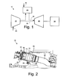
- Fig. 1 shows a schematic view of gas turbine engine 10 as may be used herein.
- the gas turbine engine 10 may include a compressor 15.
- the compressor 15 compresses an incoming flow of air 20.
- the compressor 15 delivers the compressed flow of air 20 to a combustor 25.
- the combustor 25 mixes the compressed flow of air 20 with a pressurized flow of fuel 30 and ignites the mixture to create a flow of combustion gases 35.
- the gas turbine engine 10 may include any number of combustors 25.
- the flow of combustion gases 35 is in turn delivered to a turbine 40.
- the flow of combustion gases 35 drives the turbine 40 so as to produce mechanical work.
- the mechanical work produced in the turbine 40 drives the compressor 15 via a shaft 45 and an external load 50 such as an electrical generator and the like.
- Other configurations and other components may be used herein.
- the gas turbine engine 10 may use natural gas, various types of syngas, and/or other types of fuels.
- the gas turbine engine 10 may be any one of a number of different gas turbine engines offered by General Electric Company of Schenectady, New York, including, but not limited to, those such as a 7 or a 9 series heavy duty gas turbine engine and the like.
- the gas turbine engine 10 may have different configurations and may use other types of components.
- Other types of gas turbine engines also may be used herein.
- Multiple gas turbine engines, other types of turbines, and other types of power generation equipment also may be used herein together.
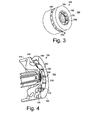
- Fig. 2 shows an example of the combustor 25 that may be used with the gas turbine engine 10 and the like.
- the combustor 25 may include a number of fuel nozzles 55 therein. As described above, each of the fuel nozzles 55 may direct a flow of air 20, a flow of fuel 30, and optional flows of other fluids into the combustor 25 for combustion therein. Any number of the fuel nozzles 55 may be used in any configuration.
- the fuel nozzles 55 may be attached to an end cover 60 near a head end 65 of the combustor 25. The flows of air 20 and fuel 30 may be directed through the end cover 60 and the head end 65 to each of the fuel nozzles 55 so as to distribute a fuel-air mixture therein.
- the combustor 25 also may include a combustion chamber 70 therein.
- the combustion chamber 70 may be defined by a combustion casing 75, a combustion liner 80, a flow sleeve 85, and the like.
- the liner 80 and the flow sleeve 85 may be coaxially positioned with respect to one another so as to define an air pathway 90 for the flow of air 20 therethrough.
- the combustion chamber 70 may lead to a downstream transition piece 95.
- the flows of air 20 and fuel 30 may mix downstream of the fuel nozzles 55 for combustion within the combustion chamber 70.
- the flow of combustion gases 35 then may be directed via the transition piece 95 towards the turbine 40 so as to produce useful work therein.
- Other components and other configuration also may be used herein.
- the fuel nozzle 100 may include an outer tube 110.
- the outer tube 110 may lead to a downstream face 120 with a fuel nozzle tip 130.
- the outer tube 110 may include a number of fuel and air passages therein. Specifically, a number of fuel passages 140 may extend therethrough and may be axially positioned about the downstream face 120.
- the fuel passages 140 may be in communication with the flow of fuel 30.
- a number of tip outlets 150 also may extend therethrough and may be positioned about the fuel nozzle tip 130.
- the tip outlets 150 may be in communication with the flow of fuel 30, the flow of air 20, or other types of flows.
- the flows of fuel 30 extending through the fuel passages 140 and through the tip outlets 150 may be the same and/or different types of fuel flows depending upon the nature of the combustion and other types of parameters. Other components and other configurations also may be used herein.
- a number of recirculation zones 190 may be formed as a result of the interaction between the flows of air 20 and fuel 30. These recirculation zones 190 may lead to flame holding about the fuel nozzle 100 via a region of low velocity.
- a number of purge holes 200 may be positioned through the air vanes 170.
- the purge holes 200 may have any size, shape, or configuration. Any number of the purge hole 200 may be used herein.
- the purge holes 200 may be angled and/or multiple angles may be used herein. Additional purge holes 200 also may extend through the downstream ring 180 and/or elsewhere. Other components and other configurations may be used herein.
- the purge holes 200 thus provide for a flow of purge air 210 therethrough as part of the overall flow of air 20.
- the flow of purge air 210 through the purge holes 200 may disrupt the recirculation zones 190 downstream of the fuel nozzles 100 caused by the regions of low velocity or otherwise.
- the purge holes 200 may be angled such that the purge air 210 disrupts the creation of the recirculation zones 190 in a substantially circumferential direction. Elimination or reduction of these recirculation zones 190 along the circumferential direction should reduce flame holding thereon. As such, the reduction in flame holding should provide the fuel nozzle 100 with improved durability and lifetime.
- the overall gas turbine engine 100 may have improved emissions and overall improved performance.
- the use of the purge holes 200 with the flow of purge air 210 therethrough may be original equipment or added as part of a retrofit.
Landscapes
- Engineering & Computer Science (AREA)
- Chemical & Material Sciences (AREA)
- Combustion & Propulsion (AREA)
- Mechanical Engineering (AREA)
- General Engineering & Computer Science (AREA)
- Pre-Mixing And Non-Premixing Gas Burner (AREA)
- Spray-Type Burners (AREA)
Abstract
Description
- The present invention relates generally to a gas turbine engine and more particularly relate to a fuel nozzle with a nozzle collar having a number of purge holes therein for improved fuel-air mixing, flame holding resistance, and overall performance.
- Generally described, a gas turbine engine may employ one or more fuel nozzles to facilitate fuel-air mixing in a combustor. Each fuel nozzle may direct a flow of fuel, a flow of air, and optional flows of other fluids into the combustor for combustion therein. In certain conditions, a combustion flame may flash back and/or hold to a surface of the fuel nozzle. Flame holding may cause significant damage to the fuel nozzles and/or reduce the performance of the fuel nozzles and the overall gas turbine engine.
- Specifically, flame holding may occur if a flammable fuel-air mixture resides in a low velocity region in close proximity to a combustion source. In fuel nozzles used in diffusion based combustion systems, low velocity regions generally may be found near the interior walls of the fuel nozzles due to the aerodynamics therein. Such a flammable mixture potentially may result in flame holding inside the fuel nozzles. Flame holding inside fuel nozzles may result in the fuel nozzles burning out, i.e., experiencing flame damage therein.
- There is thus a desire for an improved fuel nozzle design. Preferably such an improved fuel nozzle design may limit or reduce flammable fuel/air mixtures in low velocity regions about the fuel nozzles so as to limit flame holding and the like. Limiting flame holding should improve the overall performance and durability of the fuel nozzles and the gas turbine engine.
- The present invention provides an example of a fuel nozzle for mixing a flow of fuel and a flow of air. The fuel nozzle may include a downstream face, a number of fuel passages positioned about the downstream face for the flow of fuel, and a nozzle collar position about the downstream face. The nozzle collar may include a number of air vanes for the flow of air and one or more purge holes therethrough.
- The present invention further provides an example of a method of limiting flame holding about a fuel nozzle. The method may include the steps of providing a flow of fuel through a downstream face of the fuel nozzle, providing a flow of air through a number of air vanes of a nozzle collar of the fuel nozzle, mixing the flow of fuel and the flow of air downstream of the fuel nozzle, providing a flow of purge air through a number of purge holes in the air vanes, and limiting the creation of one or more recirculation zones downstream of the fuel nozzle with the flow of purge air.
- The present invention further provides an example of a combustor for use with a gas turbine engine. The combustor may include a combustion chamber and a number of fuel nozzles positioned about the combustion chamber. Each of the fuel nozzles may include a nozzle collar thereon. The nozzle collar may include one or more air vanes with one or more purge holes for a flow of purge air therethrough.
- These and other features and improvements of the present application and the resultant patent will become apparent to one of ordinary skill in the art upon review of the following detailed description when taken in conjunction with the several drawings and the appended claims.
- Embodiments of the present invention will now be described, by way of example only, with reference to the accompanying drawings in which:
-
Fig. 1 is a schematic diagram of a gas turbine engine showing a compressor, a combustor, and a turbine. -
Fig. 2 is a side view of an example of the compressor such as that shown inFig. 1 . -
Fig. 3 is a perspective view of an example of a fuel nozzle with a nozzle collar as may be described herein. -
Fig. 4 is a partial side cross-sectional view of the fuel nozzle with the nozzle collar ofFig. 3 . - Referring now to the drawings, in which like numerals refer to like elements throughout the several views,
Fig. 1 shows a schematic view ofgas turbine engine 10 as may be used herein. Thegas turbine engine 10 may include acompressor 15. Thecompressor 15 compresses an incoming flow ofair 20. Thecompressor 15 delivers the compressed flow ofair 20 to acombustor 25. Thecombustor 25 mixes the compressed flow ofair 20 with a pressurized flow offuel 30 and ignites the mixture to create a flow ofcombustion gases 35. Although only asingle combustor 25 is shown, thegas turbine engine 10 may include any number ofcombustors 25. The flow ofcombustion gases 35 is in turn delivered to aturbine 40. The flow ofcombustion gases 35 drives theturbine 40 so as to produce mechanical work. The mechanical work produced in theturbine 40 drives thecompressor 15 via ashaft 45 and anexternal load 50 such as an electrical generator and the like. Other configurations and other components may be used herein. - The
gas turbine engine 10 may use natural gas, various types of syngas, and/or other types of fuels. Thegas turbine engine 10 may be any one of a number of different gas turbine engines offered by General Electric Company of Schenectady, New York, including, but not limited to, those such as a 7 or a 9 series heavy duty gas turbine engine and the like. Thegas turbine engine 10 may have different configurations and may use other types of components. Other types of gas turbine engines also may be used herein. Multiple gas turbine engines, other types of turbines, and other types of power generation equipment also may be used herein together. -
Fig. 2 shows an example of thecombustor 25 that may be used with thegas turbine engine 10 and the like. Thecombustor 25 may include a number offuel nozzles 55 therein. As described above, each of thefuel nozzles 55 may direct a flow ofair 20, a flow offuel 30, and optional flows of other fluids into thecombustor 25 for combustion therein. Any number of thefuel nozzles 55 may be used in any configuration. Thefuel nozzles 55 may be attached to anend cover 60 near ahead end 65 of thecombustor 25. The flows ofair 20 andfuel 30 may be directed through theend cover 60 and thehead end 65 to each of thefuel nozzles 55 so as to distribute a fuel-air mixture therein. - The
combustor 25 also may include acombustion chamber 70 therein. Thecombustion chamber 70 may be defined by acombustion casing 75, acombustion liner 80, aflow sleeve 85, and the like. Theliner 80 and theflow sleeve 85 may be coaxially positioned with respect to one another so as to define anair pathway 90 for the flow ofair 20 therethrough. Thecombustion chamber 70 may lead to adownstream transition piece 95. The flows ofair 20 andfuel 30 may mix downstream of thefuel nozzles 55 for combustion within thecombustion chamber 70. The flow ofcombustion gases 35 then may be directed via thetransition piece 95 towards theturbine 40 so as to produce useful work therein. Other components and other configuration also may be used herein. -
Fig. 3 and Fig. 4 show an example of afuel nozzle 100 as may be described herein. Thefuel nozzle 100 may include anouter tube 110. Theouter tube 110 may lead to adownstream face 120 with afuel nozzle tip 130. Theouter tube 110 may include a number of fuel and air passages therein. Specifically, a number offuel passages 140 may extend therethrough and may be axially positioned about thedownstream face 120. Thefuel passages 140 may be in communication with the flow offuel 30. A number oftip outlets 150 also may extend therethrough and may be positioned about thefuel nozzle tip 130. Thetip outlets 150 may be in communication with the flow offuel 30, the flow ofair 20, or other types of flows. The flows offuel 30 extending through thefuel passages 140 and through thetip outlets 150 may be the same and/or different types of fuel flows depending upon the nature of the combustion and other types of parameters. Other components and other configurations also may be used herein. - The
fuel nozzle 100 also may include anozzle collar 160 positioned about the downstream end of theouter tube 110. Thenozzle collar 160 may surround thedownstream face 120 and thefuel nozzle tip 130. Thenozzle collar 160 may include a number ofair vanes 170. The air vanes 170 may be angled so as to direct the flow ofair 20 therethrough and/or to impart swirl therein. The air vanes 170 may have size, shape, or configuration. Any number of theair vanes 170 may be used. The air vanes 170 may direct the flow ofair 20 about thefuel passages 140 and thetip outlets 150. The air vanes 170 may support adownstream ring 180 at the end thereof. Other components and other configurations also may be used herein. - As described above, a number of
recirculation zones 190 may be formed as a result of the interaction between the flows ofair 20 andfuel 30. Theserecirculation zones 190 may lead to flame holding about thefuel nozzle 100 via a region of low velocity. As a result, a number of purge holes 200 may be positioned through theair vanes 170. The purge holes 200 may have any size, shape, or configuration. Any number of thepurge hole 200 may be used herein. The purge holes 200 may be angled and/or multiple angles may be used herein. Additional purge holes 200 also may extend through thedownstream ring 180 and/or elsewhere. Other components and other configurations may be used herein. - The purge holes 200 thus provide for a flow of
purge air 210 therethrough as part of the overall flow ofair 20. The flow ofpurge air 210 through the purge holes 200 may disrupt therecirculation zones 190 downstream of thefuel nozzles 100 caused by the regions of low velocity or otherwise. The purge holes 200 may be angled such that thepurge air 210 disrupts the creation of therecirculation zones 190 in a substantially circumferential direction. Elimination or reduction of theserecirculation zones 190 along the circumferential direction should reduce flame holding thereon. As such, the reduction in flame holding should provide thefuel nozzle 100 with improved durability and lifetime. Moreover, the overallgas turbine engine 100 may have improved emissions and overall improved performance. The use of the purge holes 200 with the flow ofpurge air 210 therethrough may be original equipment or added as part of a retrofit. - It should be apparent that the foregoing relates only to certain embodiments of the present application and the resultant patent. Numerous changes and modifications may be made herein by one of ordinary skill in the art without departing from the general spirit and scope of the invention as defined by the following claims and the equivalents thereof.
Claims (15)
- A fuel nozzle (100) for mixing a flow of fuel (30) and a flow of air (20), comprising:a downstream face (120);a plurality of fuel passages (140) positioned about the downstream face (120) for the flow of fuel (30) therethrough;a nozzle collar (16) positioned about the downstream face (120), the nozzle collar (160) comprising a plurality of air vanes (170) for the flow of air therethrough and one or more of the plurality of air vanes (170) comprising one or more purge holes (200) therethrough.
- The fuel nozzle of claim 1, further comprising an outer tube (110) with the plurality of fuel passages (140) extending therethrough to the downstream face (120).
- The fuel nozzle of claim 1 or 2, wherein the downstream face (120) comprises a fuel nozzle tip (130) positioned thereon.
- The fuel nozzle of claim 3, wherein the fuel nozzle tip (130) comprises one or more tip outlets (150) positioned thereon for the flow of fuel (30) and/or the flow of air (20) therethrough.
- The fuel nozzle of claim 4, wherein the flow of fuel (30) through the plurality of fuel passages (140) comprises a first flow of fuel and wherein the flow of fuel through the one or more tip outlets (150) comprises a second flow of fuel.
- The fuel nozzle of any preceding claim, wherein the nozzle collar (160) comprises a downstream ring (180) adjacent to the plurality of air vanes (170).
- The fuel nozzle of any preceding claim, further comprising a plurality of fuel nozzles (100) positioned about a combustion chamber (70).
- The fuel nozzle of any preceding claim, further comprising a flow of purge air (210) through the one or more purge holes (200).
- The fuel nozzle of claim 8, wherein the flow of purge air (210) through the one or more purge holes (200) limits a zone of recirculation (190) of the flow of fuel (30) and the flow of air (20) downstream of the fuel nozzle (100) which limits flame holding about the fuel nozzle (100).
- A combustor (25) for use with a gas turbine engine (10), comprising:a combustion chamber (70); anda plurality of fuel nozzles (100) positioned about the combustion chamber (70);each of the plurality of fuel nozzles (100) as recited in any of claims 1 to 9.
- A method of limiting flame holding about a fuel nozzle, (100) comprising:providing a flow of fuel (30) through a downstream face (120) of the fuel nozzle (100);providing a flow of air (20) through a plurality of air vanes (170) of a nozzle collar (160) of the fuel nozzle (100);mixing the flow of fuel (30) and the flow of air (20) downstream of the fuel nozzle (100);providing a flow of purge air (210) through a plurality of purge holes (200) in the plurality of air vanes (170); andlimiting the creation of one or more recirculation zones (190) downstream of the fuel nozzle (55) with the flow of purge air (210).
- The method of claim 11, wherein the step of providing a flow of fuel (30) comprises providing a flow of fuel (30) through a plurality of fuel passages (140).
- The method of claim 11 or 12, wherein the step of providing a flow of fuel comprises providing a flow of fuel (30) through a plurality of tip outlets (150) in a fuel nozzle tip (55).
- The method of any of claims 11 to 13, wherein the step of providing a flow of air (20) through a plurality of air vanes (170) comprises providing the flow of air (20) though a plurality of angled air vanes.
- The method of any of claims 11 to 14, wherein the step of limiting the creation of one or more recirculation zones (190) comprises limiting the creation of one or more recirculation zones (190) extending in a circumferential direction.
Applications Claiming Priority (1)
| Application Number | Priority Date | Filing Date | Title |
|---|---|---|---|
| US13/355,580 US20130189632A1 (en) | 2012-01-23 | 2012-01-23 | Fuel nozzel |
Publications (1)
| Publication Number | Publication Date |
|---|---|
| EP2618052A1 true EP2618052A1 (en) | 2013-07-24 |
Family
ID=47563290
Family Applications (1)
| Application Number | Title | Priority Date | Filing Date |
|---|---|---|---|
| EP20130152025 Withdrawn EP2618052A1 (en) | 2012-01-23 | 2013-01-21 | Fuel Nozzle |
Country Status (5)
| Country | Link |
|---|---|
| US (1) | US20130189632A1 (en) |
| EP (1) | EP2618052A1 (en) |
| JP (1) | JP2013148341A (en) |
| CN (1) | CN103216849A (en) |
| RU (1) | RU2013102632A (en) |
Families Citing this family (5)
| Publication number | Priority date | Publication date | Assignee | Title |
|---|---|---|---|---|
| EP2940389A1 (en) * | 2014-05-02 | 2015-11-04 | Siemens Aktiengesellschaft | Combustor burner arrangement |
| US9803552B2 (en) | 2015-10-30 | 2017-10-31 | General Electric Company | Turbine engine fuel injection system and methods of assembling the same |
| US10775048B2 (en) * | 2017-03-15 | 2020-09-15 | General Electric Company | Fuel nozzle for a gas turbine engine |
| CN107166435A (en) * | 2017-07-07 | 2017-09-15 | 西安富兰克石油技术有限公司 | A kind of multi fuel nozzle, fuel spray system and its turbogenerator |
| US11680709B2 (en) * | 2020-10-26 | 2023-06-20 | Solar Turbines Incorporated | Flashback resistant premixed fuel injector for a gas turbine engine |
Citations (3)
| Publication number | Priority date | Publication date | Assignee | Title |
|---|---|---|---|---|
| US6311496B1 (en) * | 1997-12-19 | 2001-11-06 | Alstom Gas Turbines Limited | Gas turbine fuel/air mixing arrangement with outer and inner radial inflow swirlers |
| EP1243854A1 (en) * | 2001-03-09 | 2002-09-25 | ALSTOM (Switzerland) Ltd | Fuel injector |
| US20080000234A1 (en) * | 2006-06-29 | 2008-01-03 | Snecma | Device for injecting a mixture of air and fuel, and combustion chamber and turbomachine provided with such a device |
Family Cites Families (32)
| Publication number | Priority date | Publication date | Assignee | Title |
|---|---|---|---|---|
| US4155220A (en) * | 1977-01-21 | 1979-05-22 | Westinghouse Electric Corp. | Combustion apparatus for a gas turbine engine |
| JPS57187531A (en) * | 1981-05-12 | 1982-11-18 | Hitachi Ltd | Low nox gas turbine burner |
| US5193346A (en) * | 1986-11-25 | 1993-03-16 | General Electric Company | Premixed secondary fuel nozzle with integral swirler |
| US5345768A (en) * | 1993-04-07 | 1994-09-13 | General Electric Company | Dual-fuel pre-mixing burner assembly |
| EP0935097B1 (en) * | 1998-02-09 | 2004-09-01 | Mitsubishi Heavy Industries, Ltd. | Combustor |
| US6082113A (en) * | 1998-05-22 | 2000-07-04 | Pratt & Whitney Canada Corp. | Gas turbine fuel injector |
| US6547163B1 (en) * | 1999-10-01 | 2003-04-15 | Parker-Hannifin Corporation | Hybrid atomizing fuel nozzle |
| US6655145B2 (en) * | 2001-12-20 | 2003-12-02 | Solar Turbings Inc | Fuel nozzle for a gas turbine engine |
| US7000403B2 (en) * | 2004-03-12 | 2006-02-21 | Power Systems Mfg., Llc | Primary fuel nozzle having dual fuel capability |
| US7251940B2 (en) * | 2004-04-30 | 2007-08-07 | United Technologies Corporation | Air assist fuel injector for a combustor |
| JP4070758B2 (en) * | 2004-09-10 | 2008-04-02 | 三菱重工業株式会社 | Gas turbine combustor |
| US7237730B2 (en) * | 2005-03-17 | 2007-07-03 | Pratt & Whitney Canada Corp. | Modular fuel nozzle and method of making |
| EP1821035A1 (en) * | 2006-02-15 | 2007-08-22 | Siemens Aktiengesellschaft | Gas turbine burner and method of mixing fuel and air in a swirling area of a gas turbine burner |
| US8276836B2 (en) * | 2007-07-27 | 2012-10-02 | General Electric Company | Fuel nozzle assemblies and methods |
| US20090111063A1 (en) * | 2007-10-29 | 2009-04-30 | General Electric Company | Lean premixed, radial inflow, multi-annular staged nozzle, can-annular, dual-fuel combustor |
| US8113000B2 (en) * | 2008-09-15 | 2012-02-14 | Siemens Energy, Inc. | Flashback resistant pre-mixer assembly |
| US8186165B2 (en) * | 2009-03-16 | 2012-05-29 | General Electric Company | Turbine fuel nozzle having heat control |
| US8256226B2 (en) * | 2009-04-23 | 2012-09-04 | General Electric Company | Radial lean direct injection burner |
| US8607570B2 (en) * | 2009-05-06 | 2013-12-17 | General Electric Company | Airblown syngas fuel nozzle with diluent openings |
| US20100281869A1 (en) * | 2009-05-06 | 2010-11-11 | Mark Allan Hadley | Airblown Syngas Fuel Nozzle With Diluent Openings |
| US8359870B2 (en) * | 2009-05-12 | 2013-01-29 | General Electric Company | Automatic fuel nozzle flame-holding quench |
| US20110005189A1 (en) * | 2009-07-08 | 2011-01-13 | General Electric Company | Active Control of Flame Holding and Flashback in Turbine Combustor Fuel Nozzle |
| US20110107769A1 (en) * | 2009-11-09 | 2011-05-12 | General Electric Company | Impingement insert for a turbomachine injector |
| US20110225973A1 (en) * | 2010-03-18 | 2011-09-22 | General Electric Company | Combustor with Pre-Mixing Primary Fuel-Nozzle Assembly |
| US8959921B2 (en) * | 2010-07-13 | 2015-02-24 | General Electric Company | Flame tolerant secondary fuel nozzle |
| US8418469B2 (en) * | 2010-09-27 | 2013-04-16 | General Electric Company | Fuel nozzle assembly for gas turbine system |
| US8579211B2 (en) * | 2011-01-06 | 2013-11-12 | General Electric Company | System and method for enhancing flow in a nozzle |
| US20120208137A1 (en) * | 2011-02-11 | 2012-08-16 | General Electric Company | System and method for operating a combustor |
| US20120208136A1 (en) * | 2011-02-11 | 2012-08-16 | General Electric Company | System and method for operating a combustor |
| US20120208135A1 (en) * | 2011-02-11 | 2012-08-16 | General Electric Company | System and method for operating a combustor |
| US9371989B2 (en) * | 2011-05-18 | 2016-06-21 | General Electric Company | Combustor nozzle and method for supplying fuel to a combustor |
| US8978384B2 (en) * | 2011-11-23 | 2015-03-17 | General Electric Company | Swirler assembly with compressor discharge injection to vane surface |
-
2012
- 2012-01-23 US US13/355,580 patent/US20130189632A1/en not_active Abandoned
-
2013
- 2013-01-17 JP JP2013005861A patent/JP2013148341A/en active Pending
- 2013-01-21 EP EP20130152025 patent/EP2618052A1/en not_active Withdrawn
- 2013-01-22 CN CN2013100231995A patent/CN103216849A/en active Pending
- 2013-01-22 RU RU2013102632/06A patent/RU2013102632A/en not_active Application Discontinuation
Patent Citations (3)
| Publication number | Priority date | Publication date | Assignee | Title |
|---|---|---|---|---|
| US6311496B1 (en) * | 1997-12-19 | 2001-11-06 | Alstom Gas Turbines Limited | Gas turbine fuel/air mixing arrangement with outer and inner radial inflow swirlers |
| EP1243854A1 (en) * | 2001-03-09 | 2002-09-25 | ALSTOM (Switzerland) Ltd | Fuel injector |
| US20080000234A1 (en) * | 2006-06-29 | 2008-01-03 | Snecma | Device for injecting a mixture of air and fuel, and combustion chamber and turbomachine provided with such a device |
Also Published As
| Publication number | Publication date |
|---|---|
| CN103216849A (en) | 2013-07-24 |
| RU2013102632A (en) | 2014-07-27 |
| JP2013148341A (en) | 2013-08-01 |
| US20130189632A1 (en) | 2013-07-25 |
Similar Documents
| Publication | Publication Date | Title |
|---|---|---|
| EP2626635B1 (en) | Combustor assembly with trapped vortex cavity | |
| US8943832B2 (en) | Fuel nozzle assembly for use in turbine engines and methods of assembling same | |
| US8161750B2 (en) | Fuel nozzle for a turbomachine | |
| CN107923620B (en) | System and method for a multi-fuel premixing nozzle with integral liquid injector/evaporator | |
| US8733108B2 (en) | Combustor and combustor screech mitigation methods | |
| JP2010169385A (en) | Bundled multi-tube nozzle for turbomachine | |
| US9404659B2 (en) | Systems and methods for late lean injection premixing | |
| CN106016365B (en) | System and method for creating a seal around a liquid fuel injector | |
| EP2618052A1 (en) | Fuel Nozzle | |
| US9696037B2 (en) | Liner retaining feature for a combustor | |
| EP2505921B1 (en) | Combustor crossfire tube having purge holes | |
| EP3098516A1 (en) | Injection boss for a unibody combustor | |
| EP2495417A2 (en) | Combustor with a pre-nozzle mixing cap assembly | |
| EP2503243A1 (en) | Combustor with fuel nozzle liner having chevron ribs | |
| EP2647910A2 (en) | Diffusion combustor fuel nozzle | |
| US20140260302A1 (en) | DIFFUSION COMBUSTOR FUEL NOZZLE FOR LIMITING NOx EMISSIONS | |
| US9175855B2 (en) | Combustion nozzle with floating aft plate | |
| US20160252253A1 (en) | Enhanced mixing tube elements | |
| US9528703B2 (en) | Micro-mixer fuel plenum and methods for fuel tube installation | |
| US9500367B2 (en) | Combustion casing manifold for high pressure air delivery to a fuel nozzle pilot system |
Legal Events
| Date | Code | Title | Description |
|---|---|---|---|
| PUAI | Public reference made under article 153(3) epc to a published international application that has entered the european phase |
Free format text: ORIGINAL CODE: 0009012 |
|
| AK | Designated contracting states |
Kind code of ref document: A1 Designated state(s): AL AT BE BG CH CY CZ DE DK EE ES FI FR GB GR HR HU IE IS IT LI LT LU LV MC MK MT NL NO PL PT RO RS SE SI SK SM TR |
|
| AX | Request for extension of the european patent |
Extension state: BA ME |
|
| 17P | Request for examination filed |
Effective date: 20140124 |
|
| RBV | Designated contracting states (corrected) |
Designated state(s): AL AT BE BG CH CY CZ DE DK EE ES FI FR GB GR HR HU IE IS IT LI LT LU LV MC MK MT NL NO PL PT RO RS SE SI SK SM TR |
|
| 17Q | First examination report despatched |
Effective date: 20140708 |
|
| GRAP | Despatch of communication of intention to grant a patent |
Free format text: ORIGINAL CODE: EPIDOSNIGR1 |
|
| INTG | Intention to grant announced |
Effective date: 20150518 |
|
| GRAP | Despatch of communication of intention to grant a patent |
Free format text: ORIGINAL CODE: EPIDOSNIGR1 |
|
| INTG | Intention to grant announced |
Effective date: 20151023 |
|
| INTG | Intention to grant announced |
Effective date: 20151028 |
|
| STAA | Information on the status of an ep patent application or granted ep patent |
Free format text: STATUS: THE APPLICATION IS DEEMED TO BE WITHDRAWN |
|
| 18D | Application deemed to be withdrawn |
Effective date: 20160308 |