EP2495417A2 - Combustor with a pre-nozzle mixing cap assembly - Google Patents
Combustor with a pre-nozzle mixing cap assembly Download PDFInfo
- Publication number
- EP2495417A2 EP2495417A2 EP12157396A EP12157396A EP2495417A2 EP 2495417 A2 EP2495417 A2 EP 2495417A2 EP 12157396 A EP12157396 A EP 12157396A EP 12157396 A EP12157396 A EP 12157396A EP 2495417 A2 EP2495417 A2 EP 2495417A2
- Authority
- EP
- European Patent Office
- Prior art keywords
- fuel
- flow
- air
- tubes
- cap assembly
- Prior art date
- Legal status (The legal status is an assumption and is not a legal conclusion. Google has not performed a legal analysis and makes no representation as to the accuracy of the status listed.)
- Withdrawn
Links
Images


Classifications
-
- F—MECHANICAL ENGINEERING; LIGHTING; HEATING; WEAPONS; BLASTING
- F23—COMBUSTION APPARATUS; COMBUSTION PROCESSES
- F23R—GENERATING COMBUSTION PRODUCTS OF HIGH PRESSURE OR HIGH VELOCITY, e.g. GAS-TURBINE COMBUSTION CHAMBERS
- F23R3/00—Continuous combustion chambers using liquid or gaseous fuel
- F23R3/28—Continuous combustion chambers using liquid or gaseous fuel characterised by the fuel supply
- F23R3/286—Continuous combustion chambers using liquid or gaseous fuel characterised by the fuel supply having fuel-air premixing devices
-
- F—MECHANICAL ENGINEERING; LIGHTING; HEATING; WEAPONS; BLASTING
- F02—COMBUSTION ENGINES; HOT-GAS OR COMBUSTION-PRODUCT ENGINE PLANTS
- F02C—GAS-TURBINE PLANTS; AIR INTAKES FOR JET-PROPULSION PLANTS; CONTROLLING FUEL SUPPLY IN AIR-BREATHING JET-PROPULSION PLANTS
- F02C7/00—Features, components parts, details or accessories, not provided for in, or of interest apart form groups F02C1/00 - F02C6/00; Air intakes for jet-propulsion plants
- F02C7/22—Fuel supply systems
Abstract
Description
- The present application relates generally to gas turbine engine combustors and more particularly relates to a combustor with a pre-nozzle mixing cap assembly for mixing fuel and air upstream of the fuel nozzles and having a cooling flow of air extending therethrough.
- In a gas turbine engine, operational efficiency generally increases as the temperature of the combustion stream increases. Higher combustion stream temperatures, however, may produce higher levels of nitrogen oxides ("NOx") and other types of emissions. Such emissions may be subject to both federal and state regulation in the United States and also subject to similar regulations abroad. A balancing act thus exists between operating the gas turbine engine in an efficient temperature range while also ensuring that the output of NOx and other types of regulated emissions remain below the mandated levels.
- Several types of known gas turbine engine designs, such as those using Dry Low NOx ("DLN") combustors, generally premix the fuel flows and the air flows upstream of a reaction or a combustion zone so as to reduce NOx emissions via a number of premixing fuel nozzles. Such premixing tends to reduce overall combustion temperatures and, hence, NOx emissions and the like.
- Premixing, however, also may present several operational issues such as flame holding, flashback, auto-ignition, and the like. These issues may be a particular concern with the use of highly reactive fuels. For example, a flame may be present in the head-end of a combustor upstream of the fuel nozzles with any significant fraction of hydrogen or other types of fuels. Any type of fuel rich pocket thus may sustain a flame and cause damage to the combustor.
- Other premixing issues may be due to irregularities in the fuel flows and the air flows. For example, there are several flow obstructions that may disrupt the flow through an incoming pathway between a flow sleeve and a liner. With a combustor having fuel injector vanes that inject fuel into the airflow upstream of the head-end, these flow disturbances may create flow recirculation zones on the trailing edge of the vanes. These recirculation zones may lead to stable pockets of ignitable fuel-air mixtures that can in turn lead to flame holding or other types of combustion events given an ignition source.
- There is thus a desire for an improved gas turbine combustor design. Preferably such a combustor design may provide fuel injection that may be less prone to flame holding. Likewise, such a combustor design also may provide faster mixing so as to limit the risk of flame holding. Such a combustor design preferably can accommodate different types of fuels.
- The present invention resides in a pre-nozzle mixing cap assembly positioned about a cap member of a combustor for mixing a flow of air and a flow of fuel. The pre-nozzle mixing cap assembly may include a fuel plenum in communication with the flow of fuel and a number of tubes in communication with the flow of air and extending through the fuel plenum. Each of the tubes may include a number of fuel holes therein such that the flow of fuel in the fuel plenum passes through the fuel holes and mixes with the flow of air.
- The present invention resides in a method of mixing a flow of air and a flow of fuel about a cap member with a number of fuel nozzles of a combustor. The method may include the steps of providing a flow of air to a number of tubes positioned about the cap member, providing a flow of fuel to a fuel plenum surrounding the tubes, passing the flow of fuel through a number of fuel holes in each of the tubes, and mixing the flow of air and the flow of fuel in and/or downstream of the tubes.
- These and other features and improvements of the present application will become apparent to one of ordinary skill in the art upon review of the following detailed description when taken in conjunction with the several drawings and the appended claims.
- Embodiments of the present invention will now be described, by way of example only, with reference to the accompanying drawings in which:
-
Fig. 1 is a schematic view of a known gas turbine engine as may be used herein. -
Fig. 2 is a side cross-sectional view of a known combustor of the gas turbine engine. -
Fig. 3 is a perspective view of a pre-nozzle mixing cap assembly as may be described herein. -
Fig. 4 is a partial side cross-sectional view of the pre-nozzle mixing cap assembly ofFig. 3 . -
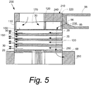
Fig. 5 is a side cross-sectional view of an alternative embodiment of a pre-nozzle mixing cap assembly as may be described herein with the addition of a cooling circuit therein. - Referring now to the drawings, in which like numerals refer to like elements throughout the several views,
Fig. 1 shows a schematic view ofgas turbine engine 10 as may be used herein. Thegas turbine engine 10 may include acompressor 15. Thecompressor 15 compresses an incoming flow ofair 20. The compressor delivers the compressed flow ofair 20 to acombustor 25. Thecombustor 25 mixes the compressed flow ofair 20 with a compressed flow offuel 30 and ignites the mixture to create a flow ofcombustion gases 35. Although only asingle combustor 25 is shown, thegas turbine engine 10 may include any number ofcombustors 25. The flow ofcombustion gases 35 is in turn delivered to aturbine 40. The flow ofcombustion gases 35 drives theturbine 40 so as to produce mechanical work. The mechanical work produced in theturbine 40 drives thecompressor 15 and anexternal load 45 such as an electrical generator and the like. - The
gas turbine engine 10 may use natural gas, various types of syngas, and/or other types of fuels. Thegas turbine engine 10 may be anyone of a number of different gas turbine engines offered by General Electric Company of Schenectady, New York, including those such as a heavy duty 9FA gas turbine engine and the like. Thegas turbine engine 10 may have different configurations and may use other types of components. Other types of gas turbine engines also may be used herein. Multiple gas turbine engines, other types of turbines, and other types of power generation equipment also may be used herein together. -
Fig. 2 shows a simplified example of a knowncombustor 25 that may be used with thegas turbine engine 10. Generally described, thecombustor 25 may include acombustion chamber 50 with a number offuel nozzles 55 positioned therein. Thefuel nozzles 55 may be positioned and supported within acap member 60 and the like. Thefuel nozzles 55 also may include a number offuel injectors 65. Thefuel injectors 65 may be positioned about one ormore swirlers 70. Theswirlers 70 aid in the premixing of the flow ofair 20 and the flows offuel 30 therein. Thefuel injectors 65 may be used with a premix fuel and the like. Other types of fuels and other types of fuel circuits may be used herein. - The flow of
air 20 may enter thecombustor 25 from thecompressor 15 via anincoming air path 75. Theincoming air path 75 may be defined between aliner 80 of thecombustion chamber 50 and anouter flow sleeve 85. The flow ofair 20 may travel along theincoming air path 75 and then reverse direction about thefuel nozzles 55. The flow ofair 20 and the flow offuel 30 may be ignited downstream of thefuel nozzles 55 within thecombustion chamber 50 such that the flow of thecombustion gases 35 may be directed towards theturbine 40. Other configurations and other components may be used herein. - The
combustor 25 also may have a lean pre-nozzlefuel injection system 90 positioned about theincoming air path 75 between theliner 80 and theflow sleeve 85. The lean pre-nozzlefuel injection system 90 may have a number of fuel pegs orfuel injectors 92. Thefuel injectors 92 may have an aerodynamic airfoil or streamline shape. Other shapes may be used herein. Thefuel injectors 92 each may have a number of injector holes 94 therein. The number and positioning of thefuel injectors 92 and the injection holes 94 may be optimized for premixing. A premix fuel or other types of fuel flows 30 may be used therein. - The
cap member 60 also may be in direct communication with a compressordischarge pressure airflow 96 via a compressor dischargepressure air path 98 and the like. The compressordischarge pressure airflow 96 may be at somewhat higher pressure than the flow ofair 20 from thecompressor 15 that travels along the entireincoming air path 75. The compressordischarge pressure airflow 96 may be used to cool thecap member 60 and possibly other components. The compressor dischargepressure air path 98 may be a direct path from thecompressor 15, a diffuser, or otherwise. Moreover, the compressor dischargepressure air path 98 may surround theflow sleeve 85 or otherwise be positioned. Other components and other configurations may be used herein. -
Figs. 3 and 4 show one example of a pre-nozzlemixing cap assembly 100 as may be described herein. The pre-nozzlemixing cap assembly 100 may be positioned about thecap body 60 and in theincoming air path 75 defined between theliner 80 and theflow sleeve 85 to receive the flow ofair 20. Likewise, thepre-nozzle mixing cap 100 may be in communication with the flow offuel 30 so as to mix the flows of fuel and air upstream of thefuel nozzles 55. The pre-nozzlemixing cap assembly 100 thus may be used in place of thefuel injectors 92 described above in the pre-nozzlefuel injection system 90 and the like. - The pre-nozzle
mixing cap assembly 100 may include at least a pair of plates, afirst plate 110 and asecond plate 120 positioned on and surrounding thecap member 60. Theplates tubes 130 may extend from thefirst plate 110 to thesecond plate 120. Thetubes 130 may have any shape, size, or configuration. Any number of thetubes 130 may be used herein. Eachtube 130 may have a chamfered edge orradius 140 about the entrance at thesecond plate 110. Eachtube 130 may have a number ofsmall fuel holes 150 positioned therein. The fuel holes 150 may have any shape, size, or configuration. Any number of the fuel holes 150 may be used herein. The length, count, and diameter of thetubes 130 and the fuel holes 150 as well as the axial locations thereof may be varied to change the overall mixing and flame holding characteristics as well as the pressure drop therethrough. - The pre-nozzle
mixing cap assembly 100 may have afuel inlet 160 in communication with the flow offuel 30. Thefuel inlet 160 may lead to afuel plenum 170 positioned between theplates fuel 30 may flow through thefuel inlet 160 and into thefuel plenum 170. The flow offuel 30 then may pass through the fuel holes 150 within eachtube 130 so as to mix with the flow ofair 20 passing therethrough before flowing downstream to thefuel nozzles 55 within thecap member 60. The flow ofair 20 and the flow offuel 30 may mix in and/or downstream of thetubes 130. Other components and other configurations may be used herein. -
Fig. 5 shows a further embodiment of a pre-nozzlemixing cap assembly 200. The mixingcap 200 may have the components of the mixingcap assembly 100 with the addition of acooling circuit 210. Thecooling circuit 210 may be defined by an additional plate, athird plate 220, positioned on the upstream end thereof. Thetubes 130 thus extend through all of theplates - In this example, the compressor discharge
pressure air path 98 may be positioned about theflow sleeve 85. The compressordischarge pressure airflow 96 thus may enter thecooling circuit 210 via a number of flow sleeve holes 230 positioned within theflow sleeve 85. Any number of the flow sleeve holes 230 may be used in any shape, size, or configuration. Thecooling circuit 210 further may include anair plenum 240 with thetubes 130 extending therethrough. Thecooling circuit 210 may end with a number of cap body holes 250 positioned about and in communication with thecap member 60. Any number of the cap body holes 250 may be used in any shape, size, or configuration. - The compressor
discharge pressure airflow 96 thus may pass from the compressor dischargepressure air path 98, through the flow sleeve holes 230, into theair plenum 240, and into thecap body 60 via the cap body holes 250. The compressordischarge pressure airflow 96 thus may be used to provide cooling for thecap body 60, particularly along acap face 260 thereof. Other components and other configurations may be used herein. - The pre-nozzle
mixing cap assemblies fuel nozzles 55. Specifically, increased mixing and faster mixing may be provided herein. With increased mixing, thecap face 260 may be moved downstream to reduce combustor volume and residence time. Shorter residence time should be desirable to meet emission targets. Likewise, faster mixing may result in a lower flame holding risk. Specifically, the overall injecting scheme may be less prone to flame holding. The higher flame holding margin also should provide the ability to burn higher reactivity fuels such as hydrogen and higher hydrocarbons. - The use of the compressor
discharge pressure airflow 96 provides improved cap face cooling and durability. Cap durability is improved by increasing the resistance to hot gases being forced upstream during periods of combustion dynamics, i.e., higher cap pressure may minimize the impact of combustion dynamics and can be used for impingement cooling. Moreover, the amount of air required for cooling should be reduced. - It should be apparent that the foregoing relates only to certain embodiments of the present application and that numerous changes and modifications may be made herein by one of ordinary skill in the art without departing from the general spirit and scope of the invention as defined by the following claims and the equivalents thereof.
Claims (15)
- A pre-nozzle mixing cap assembly (100) positioned about a cap member (60) of a combustor (25) for mixing a flow of air (20) and a flow of fuel (30), comprising:a fuel plenum (170) in communication with the flow of fuel (30); anda plurality of tubes (130) in communication with the flow of air (20) and extending through the fuel plenum (170);each of the plurality of tubes (130) comprising a plurality of fuel holes (150) therein such that the flow of fuel (30) in the fuel plenum (170) passes through the plurality of fuel holes (150) and mixes with the flow of air (20).
- The pre-nozzle mixing cap assembly (100) of claim 1, further comprising a plurality of plates (110) with the plurality of tubes (130) extending therethrough.
- The pre-nozzle mixing cap assembly (100) of claim 2, wherein the plurality of plates (110) comprises a first plate (110) and a second plate (120) and wherein the first plate (110) and the second plate (120) define the fuel plenum (170) therebetween.
- The pre-nozzle mixing cap assembly (100) of claim 3, wherein the plurality of plates (110) comprises a third plate (220) and wherein the second plate (120) and the third plate (220) define an air plenum (240) therebetween.
- The pre-nozzle mixing cap assembly (100) of any preceding claim, wherein each of the plurality of tubes (130) comprises a chamfered edge (140).
- The pre-nozzle mixing cap assembly (100) of any preceding claim, further comprising a fuel inlet (160) in communication with the flow of fuel (30) and the fuel plenum (170).
- The pre-nozzle mixing cap assembly (100) of any preceding claim, further comprising a cooling circuit (210) therein.
- The pre-nozzle mixing cap assembly (100) of claim 7, wherein the cooling circuit (210) comprises a plurality of flow sleeve holes (230).
- The pre-nozzle mixing cap assembly (100) of claim 8, wherein the cooling circuit (210) is in communication with a compressor discharge pressure airflow (96) via the plurality of flow sleeve holes (230).
- The pre-nozzle mixing cap assembly (100) of claim 7, wherein the cooling circuit (210) comprises an air plenum (240) with the plurality of tubes (130) extending therethrough.
- The pre-nozzle mixing cap assembly (100) of claim 7, wherein the cooling circuit (210) comprises a plurality of cap body holes (250) in communication with the cap body (60) so as to cool a cap face (260) thereof.
- A method of mixing a flow of air (20) and a flow of fuel (30) about a cap member (60) with a number of fuel nozzles (55) of a combustor (25), comprising:providing the flow of air (20) to a plurality of tubes (130) positioned about the cap member (60);providing the flow of fuel (30) to a fuel plenum (170) surrounding the plurality of tubes (130);passing the flow of fuel (30) through a plurality of fuel holes (150) in each of the plurality of tubes (130); andmixing the flow of air (20) and the flow of fuel (30) in and/or downstream of the plurality of tubes (130).
- The method of claim 12, further comprising the step of providing a compressor discharge pressure airflow (96) to an air plenum (240) positioned about the plurality of tubes (130).
- The method of claim 13, further comprising the step of providing the compressor discharge pressure airflow (96) to the cap member (60).
- The method of any of claims 12 to 14, further comprising the step of cooling a cap face (260) of the cap member (60).
Applications Claiming Priority (1)
| Application Number | Priority Date | Filing Date | Title |
|---|---|---|---|
| US13/040,289 US9068750B2 (en) | 2011-03-04 | 2011-03-04 | Combustor with a pre-nozzle mixing cap assembly |
Publications (2)
| Publication Number | Publication Date |
|---|---|
| EP2495417A2 true EP2495417A2 (en) | 2012-09-05 |
| EP2495417A3 EP2495417A3 (en) | 2017-11-01 |
Family
ID=45811290
Family Applications (1)
| Application Number | Title | Priority Date | Filing Date |
|---|---|---|---|
| EP12157396.8A Withdrawn EP2495417A3 (en) | 2011-03-04 | 2012-02-28 | Combustor with a pre-nozzle mixing cap assembly |
Country Status (3)
| Country | Link |
|---|---|
| US (1) | US9068750B2 (en) |
| EP (1) | EP2495417A3 (en) |
| CN (1) | CN102679400B (en) |
Families Citing this family (6)
| Publication number | Priority date | Publication date | Assignee | Title |
|---|---|---|---|---|
| US9243803B2 (en) * | 2011-10-06 | 2016-01-26 | General Electric Company | System for cooling a multi-tube fuel nozzle |
| JP6154988B2 (en) * | 2012-01-05 | 2017-06-28 | 三菱日立パワーシステムズ株式会社 | Combustor |
| US20160047316A1 (en) * | 2014-08-14 | 2016-02-18 | General Electric Company | Systems and apparatus relating to gas turbine combustors |
| US9890954B2 (en) * | 2014-08-19 | 2018-02-13 | General Electric Company | Combustor cap assembly |
| US9470421B2 (en) * | 2014-08-19 | 2016-10-18 | General Electric Company | Combustor cap assembly |
| US9964308B2 (en) * | 2014-08-19 | 2018-05-08 | General Electric Company | Combustor cap assembly |
Family Cites Families (11)
| Publication number | Priority date | Publication date | Assignee | Title |
|---|---|---|---|---|
| US4100733A (en) * | 1976-10-04 | 1978-07-18 | United Technologies Corporation | Premix combustor |
| US5491970A (en) | 1994-06-10 | 1996-02-20 | General Electric Co. | Method for staging fuel in a turbine between diffusion and premixed operations |
| US6363724B1 (en) * | 2000-08-31 | 2002-04-02 | General Electric Company | Gas only nozzle fuel tip |
| US7143583B2 (en) * | 2002-08-22 | 2006-12-05 | Hitachi, Ltd. | Gas turbine combustor, combustion method of the gas turbine combustor, and method of remodeling a gas turbine combustor |
| US7832212B2 (en) | 2006-11-10 | 2010-11-16 | General Electric Company | High expansion fuel injection slot jet and method for enhancing mixing in premixing devices |
| US8147121B2 (en) * | 2008-07-09 | 2012-04-03 | General Electric Company | Pre-mixing apparatus for a turbine engine |
| US8112999B2 (en) * | 2008-08-05 | 2012-02-14 | General Electric Company | Turbomachine injection nozzle including a coolant delivery system |
| US8327642B2 (en) | 2008-10-21 | 2012-12-11 | General Electric Company | Multiple tube premixing device |
| US8539773B2 (en) | 2009-02-04 | 2013-09-24 | General Electric Company | Premixed direct injection nozzle for highly reactive fuels |
| US8424311B2 (en) | 2009-02-27 | 2013-04-23 | General Electric Company | Premixed direct injection disk |
| US20110000215A1 (en) | 2009-07-01 | 2011-01-06 | General Electric Company | Combustor Can Flow Conditioner |
-
2011
- 2011-03-04 US US13/040,289 patent/US9068750B2/en active Active
-
2012
- 2012-02-28 EP EP12157396.8A patent/EP2495417A3/en not_active Withdrawn
- 2012-03-02 CN CN201210063809.XA patent/CN102679400B/en not_active Expired - Fee Related
Non-Patent Citations (1)
| Title |
|---|
| None |
Also Published As
| Publication number | Publication date |
|---|---|
| EP2495417A3 (en) | 2017-11-01 |
| US20130081400A1 (en) | 2013-04-04 |
| CN102679400B (en) | 2016-05-04 |
| US9068750B2 (en) | 2015-06-30 |
| CN102679400A (en) | 2012-09-19 |
Similar Documents
| Publication | Publication Date | Title |
|---|---|---|
| US9416974B2 (en) | Combustor with fuel staggering for flame holding mitigation | |
| US8991187B2 (en) | Combustor with a lean pre-nozzle fuel injection system | |
| US8327642B2 (en) | Multiple tube premixing device | |
| EP1429078B1 (en) | Apparatus for decreasing gas turbine engine combustor emissions | |
| US7490471B2 (en) | Swirler assembly | |
| US8113002B2 (en) | Combustor burner vanelets | |
| US20110179803A1 (en) | Bled diffuser fed secondary combustion system for gas turbines | |
| EP2282118A2 (en) | Methods And Systems To Thermally Protect Fuel Nozzles In Combustion Systems | |
| EP2557362A2 (en) | Turbomachine combustor assembly | |
| US8733108B2 (en) | Combustor and combustor screech mitigation methods | |
| US20110000215A1 (en) | Combustor Can Flow Conditioner | |
| US8371101B2 (en) | Radial inlet guide vanes for a combustor | |
| US9068750B2 (en) | Combustor with a pre-nozzle mixing cap assembly | |
| JP2014132214A (en) | Fuel injector for supplying fuel to combustor | |
| EP2505921B1 (en) | Combustor crossfire tube having purge holes | |
| CN106918054B (en) | Fuel nozzle assembly with premix flame holder | |
| US20120266602A1 (en) | Aerodynamic Fuel Nozzle | |
| EP2664854B1 (en) | Secondary combustion system | |
| EP2503243A1 (en) | Combustor with fuel nozzle liner having chevron ribs | |
| US20130189632A1 (en) | Fuel nozzel | |
| US9360220B2 (en) | Micro-mixer nozzle | |
| EP2647910A2 (en) | Diffusion combustor fuel nozzle | |
| US20140260302A1 (en) | DIFFUSION COMBUSTOR FUEL NOZZLE FOR LIMITING NOx EMISSIONS | |
| Zuo et al. | Radial inlet guide vanes for a combustor |
Legal Events
| Date | Code | Title | Description |
|---|---|---|---|
| PUAI | Public reference made under article 153(3) epc to a published international application that has entered the european phase |
Free format text: ORIGINAL CODE: 0009012 |
|
| AK | Designated contracting states |
Kind code of ref document: A2 Designated state(s): AL AT BE BG CH CY CZ DE DK EE ES FI FR GB GR HR HU IE IS IT LI LT LU LV MC MK MT NL NO PL PT RO RS SE SI SK SM TR |
|
| AX | Request for extension of the european patent |
Extension state: BA ME |
|
| PUAL | Search report despatched |
Free format text: ORIGINAL CODE: 0009013 |
|
| AK | Designated contracting states |
Kind code of ref document: A3 Designated state(s): AL AT BE BG CH CY CZ DE DK EE ES FI FR GB GR HR HU IE IS IT LI LT LU LV MC MK MT NL NO PL PT RO RS SE SI SK SM TR |
|
| AX | Request for extension of the european patent |
Extension state: BA ME |
|
| RIC1 | Information provided on ipc code assigned before grant |
Ipc: F02C 7/22 20060101AFI20170928BHEP |
|
| STAA | Information on the status of an ep patent application or granted ep patent |
Free format text: STATUS: REQUEST FOR EXAMINATION WAS MADE |
|
| 17P | Request for examination filed |
Effective date: 20180502 |
|
| RBV | Designated contracting states (corrected) |
Designated state(s): AL AT BE BG CH CY CZ DE DK EE ES FI FR GB GR HR HU IE IS IT LI LT LU LV MC MK MT NL NO PL PT RO RS SE SI SK SM TR |
|
| STAA | Information on the status of an ep patent application or granted ep patent |
Free format text: STATUS: EXAMINATION IS IN PROGRESS |
|
| 17Q | First examination report despatched |
Effective date: 20190205 |
|
| STAA | Information on the status of an ep patent application or granted ep patent |
Free format text: STATUS: EXAMINATION IS IN PROGRESS |
|
| STAA | Information on the status of an ep patent application or granted ep patent |
Free format text: STATUS: EXAMINATION IS IN PROGRESS |
|
| GRAP | Despatch of communication of intention to grant a patent |
Free format text: ORIGINAL CODE: EPIDOSNIGR1 |
|
| STAA | Information on the status of an ep patent application or granted ep patent |
Free format text: STATUS: GRANT OF PATENT IS INTENDED |
|
| INTG | Intention to grant announced |
Effective date: 20221116 |
|
| STAA | Information on the status of an ep patent application or granted ep patent |
Free format text: STATUS: THE APPLICATION IS DEEMED TO BE WITHDRAWN |
|
| 18D | Application deemed to be withdrawn |
Effective date: 20230328 |