EP2618042A2 - Vererbesserte Beleuchtungsanordnung für einen Operationssaal - Google Patents
Vererbesserte Beleuchtungsanordnung für einen Operationssaal Download PDFInfo
- Publication number
- EP2618042A2 EP2618042A2 EP13151548.8A EP13151548A EP2618042A2 EP 2618042 A2 EP2618042 A2 EP 2618042A2 EP 13151548 A EP13151548 A EP 13151548A EP 2618042 A2 EP2618042 A2 EP 2618042A2
- Authority
- EP
- European Patent Office
- Prior art keywords
- lighting system
- mounting
- mounting supports
- light
- set forth
- Prior art date
- Legal status (The legal status is an assumption and is not a legal conclusion. Google has not performed a legal analysis and makes no representation as to the accuracy of the status listed.)
- Granted
Links
Images


Classifications
-
- F—MECHANICAL ENGINEERING; LIGHTING; HEATING; WEAPONS; BLASTING
- F21—LIGHTING
- F21S—NON-PORTABLE LIGHTING DEVICES; SYSTEMS THEREOF; VEHICLE LIGHTING DEVICES SPECIALLY ADAPTED FOR VEHICLE EXTERIORS
- F21S8/00—Lighting devices intended for fixed installation
- F21S8/04—Lighting devices intended for fixed installation intended only for mounting on a ceiling or the like overhead structures
- F21S8/06—Lighting devices intended for fixed installation intended only for mounting on a ceiling or the like overhead structures by suspension
-
- F—MECHANICAL ENGINEERING; LIGHTING; HEATING; WEAPONS; BLASTING
- F21—LIGHTING
- F21S—NON-PORTABLE LIGHTING DEVICES; SYSTEMS THEREOF; VEHICLE LIGHTING DEVICES SPECIALLY ADAPTED FOR VEHICLE EXTERIORS
- F21S2/00—Systems of lighting devices, not provided for in main groups F21S4/00 - F21S10/00 or F21S19/00, e.g. of modular construction
-
- A—HUMAN NECESSITIES
- A61—MEDICAL OR VETERINARY SCIENCE; HYGIENE
- A61B—DIAGNOSIS; SURGERY; IDENTIFICATION
- A61B90/00—Instruments, implements or accessories specially adapted for surgery or diagnosis and not covered by any of the groups A61B1/00 - A61B50/00, e.g. for luxation treatment or for protecting wound edges
- A61B90/30—Devices for illuminating a surgical field, the devices having an interrelation with other surgical devices or with a surgical procedure
-
- A—HUMAN NECESSITIES
- A61—MEDICAL OR VETERINARY SCIENCE; HYGIENE
- A61B—DIAGNOSIS; SURGERY; IDENTIFICATION
- A61B90/00—Instruments, implements or accessories specially adapted for surgery or diagnosis and not covered by any of the groups A61B1/00 - A61B50/00, e.g. for luxation treatment or for protecting wound edges
- A61B90/30—Devices for illuminating a surgical field, the devices having an interrelation with other surgical devices or with a surgical procedure
- A61B90/35—Supports therefor
-
- F—MECHANICAL ENGINEERING; LIGHTING; HEATING; WEAPONS; BLASTING
- F21—LIGHTING
- F21K—NON-ELECTRIC LIGHT SOURCES USING LUMINESCENCE; LIGHT SOURCES USING ELECTROCHEMILUMINESCENCE; LIGHT SOURCES USING CHARGES OF COMBUSTIBLE MATERIAL; LIGHT SOURCES USING SEMICONDUCTOR DEVICES AS LIGHT-GENERATING ELEMENTS; LIGHT SOURCES NOT OTHERWISE PROVIDED FOR
- F21K9/00—Light sources using semiconductor devices as light-generating elements, e.g. using light-emitting diodes [LED] or lasers
-
- F—MECHANICAL ENGINEERING; LIGHTING; HEATING; WEAPONS; BLASTING
- F21—LIGHTING
- F21V—FUNCTIONAL FEATURES OR DETAILS OF LIGHTING DEVICES OR SYSTEMS THEREOF; STRUCTURAL COMBINATIONS OF LIGHTING DEVICES WITH OTHER ARTICLES, NOT OTHERWISE PROVIDED FOR
- F21V21/00—Supporting, suspending, or attaching arrangements for lighting devices; Hand grips
- F21V21/005—Supporting, suspending, or attaching arrangements for lighting devices; Hand grips for several lighting devices in an end-to-end arrangement, i.e. light tracks
-
- F—MECHANICAL ENGINEERING; LIGHTING; HEATING; WEAPONS; BLASTING
- F21—LIGHTING
- F21V—FUNCTIONAL FEATURES OR DETAILS OF LIGHTING DEVICES OR SYSTEMS THEREOF; STRUCTURAL COMBINATIONS OF LIGHTING DEVICES WITH OTHER ARTICLES, NOT OTHERWISE PROVIDED FOR
- F21V21/00—Supporting, suspending, or attaching arrangements for lighting devices; Hand grips
- F21V21/34—Supporting elements displaceable along a guiding element
-
- A—HUMAN NECESSITIES
- A61—MEDICAL OR VETERINARY SCIENCE; HYGIENE
- A61B—DIAGNOSIS; SURGERY; IDENTIFICATION
- A61B90/00—Instruments, implements or accessories specially adapted for surgery or diagnosis and not covered by any of the groups A61B1/00 - A61B50/00, e.g. for luxation treatment or for protecting wound edges
- A61B90/30—Devices for illuminating a surgical field, the devices having an interrelation with other surgical devices or with a surgical procedure
- A61B2090/309—Devices for illuminating a surgical field, the devices having an interrelation with other surgical devices or with a surgical procedure using white LEDs
-
- F—MECHANICAL ENGINEERING; LIGHTING; HEATING; WEAPONS; BLASTING
- F21—LIGHTING
- F21V—FUNCTIONAL FEATURES OR DETAILS OF LIGHTING DEVICES OR SYSTEMS THEREOF; STRUCTURAL COMBINATIONS OF LIGHTING DEVICES WITH OTHER ARTICLES, NOT OTHERWISE PROVIDED FOR
- F21V14/00—Controlling the distribution of the light emitted by adjustment of elements
- F21V14/02—Controlling the distribution of the light emitted by adjustment of elements by movement of light sources
-
- F—MECHANICAL ENGINEERING; LIGHTING; HEATING; WEAPONS; BLASTING
- F21—LIGHTING
- F21V—FUNCTIONAL FEATURES OR DETAILS OF LIGHTING DEVICES OR SYSTEMS THEREOF; STRUCTURAL COMBINATIONS OF LIGHTING DEVICES WITH OTHER ARTICLES, NOT OTHERWISE PROVIDED FOR
- F21V21/00—Supporting, suspending, or attaching arrangements for lighting devices; Hand grips
- F21V21/14—Adjustable mountings
- F21V21/15—Adjustable mountings specially adapted for power operation, e.g. by remote control
-
- F—MECHANICAL ENGINEERING; LIGHTING; HEATING; WEAPONS; BLASTING
- F21—LIGHTING
- F21W—INDEXING SCHEME ASSOCIATED WITH SUBCLASSES F21K, F21L, F21S and F21V, RELATING TO USES OR APPLICATIONS OF LIGHTING DEVICES OR SYSTEMS
- F21W2131/00—Use or application of lighting devices or systems not provided for in codes F21W2102/00-F21W2121/00
- F21W2131/20—Lighting for medical use
- F21W2131/205—Lighting for medical use for operating theatres
-
- F—MECHANICAL ENGINEERING; LIGHTING; HEATING; WEAPONS; BLASTING
- F21—LIGHTING
- F21Y—INDEXING SCHEME ASSOCIATED WITH SUBCLASSES F21K, F21L, F21S and F21V, RELATING TO THE FORM OR THE KIND OF THE LIGHT SOURCES OR OF THE COLOUR OF THE LIGHT EMITTED
- F21Y2115/00—Light-generating elements of semiconductor light sources
- F21Y2115/10—Light-emitting diodes [LED]
Definitions
- the invention relates to an improved lighting system as set forth in the preamble of claim, particularly for an operating theatre or the like facility.
- Operating theatre requires high quality lighting, especially for those parts of operating theatre where surgeries are performed.
- lighting is concentrated specifically on a part of the patient's body to be treated with surgical procedures.
- the conventional operating theatre lighting system comprises a general lighting arrangement and one or more surgical light fixtures set up in the proximity of and above the operating table.
- the prior known surgical light fixture comprises a fixed light fixture carrier, which is provided with a plurality of light sources such as halogen lamps or the like, and a generally pivotable spring arm for attaching the light fixture to ceiling structures and for adjusting its position relative to the operating table and the surgical patient resting thereon.
- Prior known from German patent publication DE 102006040393 is a surgical lighting fixture, which comprises a plurality of lighting segments assembled on a single carrier and implemented with light emitting diodes or LEDs equipped with optics.
- This surgical lighting fixture is also intended for attachment by way of a spring arm to the ceiling structures of an operating theatre.
- the prior known surgical lights are generally quite similar in design.
- a problem with surgical lights is particularly a carrier structure and the attachment to ceiling structures.
- the light carrier is fixed, heavy and clumsy.
- the adjustment of a lighting fixture position takes place manually with a hazard of the lighting fixture colliding with other operating theatre equipment during its relocation.
- Another problem during a procedure results from the surgeon's possible contacts with non-sterile surfaces. Cleaning the lighting fixture is also a tedious process.
- An object of the invention is to eliminate problems related to prior known surgical lights. It is also an object of the invention to provide a new improved operating theatre lighting system, which preferably enables the management of even the general lighting of an operating theatre, and particularly task lighting for an operating table and thereby for surgical procedures.
- the lighting system according to the invention is characterized by what is presented in claim 1. Preferred embodiments of the invention are presented in dependent claim.
- the invention relates to a lighting system which is implemented by means of light emitting diodes or LEDs.
- the lighting system comprises a lighthead, which is constituted by a frame fitted with a plurality of elongated rod type mounting supports, said mounting supports being provided with a plurality of light elements containing at least one light emitting diode.
- the mounting supports are organized in two groups, each of said groups including at least two mounting supports, whereof the first group is set on a first level (A-A) and the second group on a second level (B-B), such that the mounting supports of each group are apart or spaced by a gap from each other, and that the first group's mounting supports lie at an angle, most preferably at a right angle, relative to the second group's mounting supports, and the lighthead, along with its frame and mounting supports, is set up in the proximity of a ceiling (K) in the operating theatre or the like facility substantially above an operating table (LP), such that the location thereof is below the illuminated facility's incoming air frame (TF).
- K ceiling
- LP operating table
- the frame has a quadrangular shape, such as rectangular or square, said frame including first and second frame members, which are pairwise parallel.
- the lighting system has its mounting supports attached to the frame in a movable manner, such that individual mounting supports are movable relative to each other.
- clearances between the mounting supports are adjustable, yet most preferably in such a way that there is always a small gap, a minimum gap, between the mounting supports.
- the mounting supports are movable along guides, such that the air resistance thereof remains constant in a direction transverse, preferably perpendicular, relative to mounting levels established by the mounting supports.
- the mounting supports are preferably maneuvered along the guides in such a way that the lighthead's surface area, which is penetrated by an airflow arriving at the lighthead from the incoming air frame, remains substantially unchanged in a direction transverse, preferably perpendicular, relative to the mounting levels.
- this implies that the mounting supports are manipulated in such a way that, in a direction transverse relative to the mounting levels, the direction of a mounting support remains constant with respect to an airflow arriving at the lighthead from the incoming air frame (TF).
- each mounting support is fitted in the frame's guides, along which the mounting support is maneuverable with appropriate transfer means.
- the mounting supports are substantially straight rigid and dimensionally stable shafts or rods, which are preferably also channel-shaped. These are jointly or in each group most preferably set in a parallel relationship at a distance or spaced from each other to extend across an area that requires a particularly high light intensity.
- the light elements are fitted on a mounting support successively in a row at a distance from each other.
- the light elements comprise not only a light source, i.e. one or more light emitting diodes, but also adjustable optics for focusing the light emitted by the light source, and alignment elements, such as one or more reversible motors, for directing the light, especially a light beam, emitted by the light source.
- a light field produced by the lighting system can be arbitrarily manipulated. Focusing the illumination on the operating table area, and particularly on the patient's surgical site, is implementable with a lighting system of the invention.
- the focused light field is manipulable in terms of its extent and shape according to surgical requirements and the situation.
- the risk of physical contact with the lighting system's light sources, or with its components in general, is practically eliminated, and the possible access of germs to the surgical incision by way of contact with the lighting system within a sterile area in the vicinity of an operating table is prevented.
- the lighting system With respect to floor level, the lighting system is generally located at a height beyond a reach of the surgeon or any other assisting person working at the operating table. Therefore, the infection risk after a surgical procedure is lower than before.
- the assisting staff need not enter the sterile area in order to adjust a surgical light, because the surgical light is integrated in the lighting system set in the proximity of an operating theatre ceiling.
- Another benefit of the invention is that the movable and/or pivotable equipment and/or accessories of an operating theatre do not collide with the lighting system's light sources or its components in general.
- the sterile incoming airflow which is supplied in from the ceiling structures of an operating theatre and directed towards the floor, can be kept laminar.
- the mounting supports included in the lighting system are aerodynamic in the above-discussed flow direction, thereby neither blocking the passage of air nor deflecting significantly the advancing direction of air.
- the sterile airflow coming towards an operating table from above finds its way without interference to the surgical area and contributes effectively to blocking the access of germs to the surgical incision. Therefore, the infection risk after a surgical procedure is also in this respect lower than before.
- the permanent components of a lighthead such as the mounting supports, have a surface area which is small on the lighthead's level in comparison with the lightheads of available lighting systems and with respect to the attachment arms thereof. It is by virtue of the small surface area of the lighthead's permanent components that air is able to flow through the lighthead as opposed to prior known light fixtures, especially surgical light fixtures.
- a benefit in a lighting system of the invention is a simple attachment of the lighthead to ceiling structures.
- the lighthead is suspended by its various sides with suitable suspension elements, such as with a plurality of suspension ropes or the like suspenders, from ceiling structures, especially outside an area of the operating theatre defined by the incoming air frame.
- suitable suspension elements such as with a plurality of suspension ropes or the like suspenders, from ceiling structures, especially outside an area of the operating theatre defined by the incoming air frame.
- the lighthead suspension arrangement also relieves and simplifies the ceiling structure.
- a benefit of the invention is that the lighting system is simple to provide with suitable accessories, such as a camera arrangement and light focusing elements.
- a benefit offered by a lighting system of the invention is versatility and programmability, which enable various lighting functions to be performed with one and the same physical assembly.
- a benefit offered by a lighting system of the invention is a simple construction and manufacturing friendliness. Another benefit of the invention is good usability, reliability and safety.
- Still another benefit offered by a lighting system of the invention is that it is almost maintenance-free, because, i.a., the light elements equipped with LEDs have a long service life.
- the invention relates to a lighting system, which is implemented by means of light emitting diodes or LEDs.
- the lighting system according to the invention is intended particularly for an operating theatre or the like facility, yet it is also adaptable to other types of rooms or facilities, such as workrooms, which require powerful, preferably focusable illumination, i.a. for carrying out a high precision and demanding work assignment.
- the mounting supports 2 are provided with a plurality of light elements 3, comprising at least one light emitting diode 31 to function as a light source.
- the mounting supports 2 are organized in two groups 21, 22, each of said groups including at least two mounting supports 21; 21 1 , 21 2 ; 22; 22 1 , 22 2 .
- the first group 21 is set on a first level A-A and the second group 22 respectively on a second level B-B.
- the groups have their mounting supports 21; 21 1 , 21 2 ; 22; 22 1 , 22 2 spaced, i.e. with the gap 4; 4a, 4b from each other.
- the first group has its mounting supports 21; 21 1 , 21 2 at an angle, preferably at a right angle, to those of the second group 22; 22 1 , 22 2 .
- the first and second groups have their mounting supports 21, 22, and thereby their levels A-A and B-B, at a small distance, such as 25-50 mm, from each other.
- the first and second groups' mounting supports 21, 22 are vertically in alignment.
- the gaps 4; 4a, 4b between the mounting supports 2; 21, 22 in each group are unobstructed.
- the mounting supports 2; 21, 22; 21 1 , 21 2 ; 21 1 , 21 2 are aerodynamic rod type or shaft type elements, the air being readily able to flow through the gaps 4; 4a, 4b therebetween. Hence, the air is able to flow through the entire lighthead 1.
- the mounting supports produce a low air resistance in the airflow direction C-C, since the mounting supports have a sufficiently small surface area with respect to that of the gaps 4; 4a, 4b in the direction of the mounting levels A-A and B-B.
- the mounting supports 2 have a cross-section which is preferably a circle or ellipse, or at least the mounting supports 2 have a top portion 2a which is wedge-shaped and/or rounded. Thereby, the mounting supports 2 have a width I, which in the mounting level direction A-A or B-B falls preferably short of their height k.
- the airflow passing through the lighthead 1 arrives from the incoming air frame TF and proceeds through the mounting supports included in the lighthead's groups 21 and 22 in the direction C-C transverse to the respective mounting levels A-A and B-B, preferably in a perpendicular direction.
- the mounting supports have such a low air resistance in the direction of the mounting levels that the laminar airflow arriving from the incoming air frame TF passes through the lighthead in the direction C-C while retaining its laminarity.
- the mounting support 2; 21, 22; 21 1 , 21 2 ; 21 1 , 21 2 can have a length within the range of e.g. 150-300 cm, but other lengths are also possible depending on the intended use.
- the mounting support 2 has its width I for example within the bracket of 20-40 mm, but other width dimensions are also possible
- the mounting supports 2; 21, 22; 21 1 , 21 2 ; 21 1 , 21 2 are most preferably made of metal, such as aluminum or some other suchlike relatively lightweight, rigid and dimensionally stable material, such as appropriately reinforced plastic.
- the mounting supports 2 are rod type elements, which are preferably provided with a channel or a plurality of successive recesses for installing the light elements 3 therein.
- the mounting supports 2; 21, 22; 21 1 , 21 2 ; 21 1 , 21 2 are straight rods or shafts, which are disposed side by side at a distance from each other.
- the light elements 3; 3 1 , 3 2 are fitted on the mounting support 2; 21, 22; 21 1 , 21 2 ; 21 1 , 21 2 in a row successively at a small distance from each other.
- the light elements 3 are disposed on one side of a plane, i.e. the mounting level, and in such a way that the light, especially light beams 311 produced by the light elements 3, is directed away from the level A-A (and B-B) to the other side thereof.
- the width I of the mounting support 2; 21, 22; 21 1 , 21 2 ; 21 1 , 21 2 in a plane perpendicular to its longitudinal direction, and at the same time on the mounting level A-A (and B-B), is preferably not more than what is a maximum diameter a of the light element 3 in its transverse plane.
- the maximum diameter of the light element 3, especially the diameter of its optics 32, may exceed the width of the mounting support.
- the light elements 3; 3 1 , 3 2 , 3 3 comprise not only an actual light source 31, i.e. a LED, but also adjustable optics 32, i.e. a suitable lens system and alignment elements 33, such as one or more electrically driven reversible motors, which are adapted to each other and most preferably fitted in a common housing 34.
- the light element 3 comprises preferably also a suitable transparent protective hood or at least a protective coating 35, which is provided as a protection for the optics 32 and through which propagates the light produced by a light source.
- the light elements 3; 3 1 , 3 2 , 3 3 are adapted to be movable in the mounting support 2; 21, 22; 21 1 , 21 2 ; 22 1 , 22 2 , especially in its longitudinal direction.
- the light element 3 is provided for example with a transfer pad, which is in turn adapted to be movable and displaceable in the mounting support 2, such as along the mounting support's lengthwise guide (a ridge or a groove), by a suitable power unit, such as an electric motor.
- the plurality of light elements 3; 3 1 , 3 2 , 3 3 3 are accommodable on a single transfer pad, by means of which said elements can be maneuvered in the mounting support 2.
- the light elements 3; 3 1 , 3 2 , 3 3 have basic positions at a specific distance from each other, but are most preferably also movable lengthwise of the mounting support 2; 21, 22; 21 1 , 21 2 ; 22 1 , 22 2 .
- the lighthead 1 has its frame 5 most preferably in a quadratic shape, such as rectangular or square.
- the frame 5 encircles or confines the mounting supports 2.
- the frame 5 comprises first and second sides. i.e. frame members 51, 52, 53, 54, which are straight sides.
- the first frame members 51, 52 of the frame 5 and, respectively, its second frame members 53, 54 are co-directional with each other and most preferably perpendicular to each other.
- the first frame members 51, 52 of the frame 5 are attached by their ends to the ends of the frame's second members 53, 54 in such a way that said members lie in planes different from each other.
- the mounting supports 2; 21, 22 are attached to the frame 5, most preferably by the ends thereof,
- the mounting supports 2; 21, 22 are attached to the opposite parallel frame members 51, 52; 53, 54 of the frame 5.
- the mounting supports 2; 21, 22 are attached movably to the frame 5; 51, 52 in such a way that individual mounting supports in each group 21, 22 are movable relative to each other in the direction of the mounting level A-A or B-B, respectively, such that the actuation relative to each other of the mounting supports included in a specific group 21 or 22 maintains the air resistance established by the lighthead 1 unchanged in the direction C-C transverse to the mounting levels A-A and B-B.
- the gaps 4; 4a, 4b between the mounting supports are also changeable, but most preferably in such a way that there will be at least a small gap, a minimum gap, between the mounting supports.
- the airflow which passes through the light head 1, arrives from the incoming air frame TF and proceeds through the lighthead's mounting supports included in the groups 21 and 22 in the direction C-C transverse, preferably perpendicular, to the respective mounting levels A-A and B-B.
- the fact that the lighthead's air resistance remains unchanged results at the same time in a consequence that, as the lighthead 1 is placed below the incoming air frame TF and at the same time above the operating table LP, the laminar airflow arriving from the incoming air frame TF penetrates the lighthead 1 in the direction C-C while retaining its laminarity.
- Actuation of the mounting supports 2 can be effected for example in such a way that each mounting support 21; 21 1 , 21 2 ; 22; 22 1 , 22 2 has its opposite ends accommodated on guides included in the frame 5, such as in the opposite frame members 51, 52; 53, 54, along which guides the mounting support is movable with suitable transfer means.
- the mounting supports 2 are then actuated along the guides preferably in such a way that the direction of each mounting support's vertical axis, i.e. the direction of that particular axis which extends in a direction transverse to the direction of the mounting levels A-A and B-B, shall be maintained constant relative to the average direction of an airflow arriving at the lighthead in the direction C-C.
- Said guides may be constituted by the frame members themselves.
- These transfer means are implementable e.g. by means of a toothed rack or belt fitted on the guide and a gear disposed on the end of a mounting support, and by means of an electric motor, such as a stepped motor, driving the same. It should be appreciated, however, that there are a wide variety of possibilities of realizing the transfer means
- the frame 5, especially the frame members 51, 52, 53, 54, is most preferably constructed from long rod type elements, which in one embodiment of the invention are essentially similar to the mounting supports 21; 21 1 , 21 2 ; 22; 22 1 , 22 2 . It should be noted, however, that other sort of long rod type or shaft type members can also be used in the frame.
- the lighthead 1 is suspended by various sides thereof with suitable suspension elements, such a plurality of suspension ropes 62 or the like, from ceiling structures, especially outside an area defined by the incoming air frame TF of an operating theatre.
- a preferred embodiment for a lighting system of the invention comprises also displacement elements 6, which enable the lighthead 1 to be raised or lowered as necessary.
- the displacement elements 6 comprise a power unit such as one or more electric motors 61, and suspension elements such as a plurality of suspension ropes 62 or the like between the frame 5 and the drive shaft of a power unit such as the electric motor 61.
- the number of suspension elements, such as the suspension ropes 62, and the number of electric motors 61 is four on various sides of the frame 5 in the proximity of the corners of the rectangular-shaped lighthead 1 at ceiling structures.
- the displacement elements 6 enable a manipulation of the lighthead 1, i.e. the frame 5 and the mounting supports 2, in vertical direction.
- the lighthead 1 can thus be lowered downward from ceiling structures to a desired level and respectively raised back upward to the proximity of ceiling structures.
- the lighthead 1 can also be set in an inclined position by means of the displacement elements 6, if that is deemed necessary.
- a preferred embodiment for a lighting system of the invention comprises at least one accessory 7, such as a digital camera 71 and/or an electronic pointing device (a touchpad) 72 or a generally applicable remote controller.
- the camera 71 is fitted in connection with the lighthead 1, such as a suitable light support 2, and it is pointed to image in the illumination direction of the light elements 3 at least a part of the area to be illuminated.
- the camera 71 is used for monitoring the area to be illuminated.
- a screen 72a of the electronic pointing device 72 is used for viewing an image given by the camera 71 and for determining, e.g. by touching or a cursor movement, a part of the camera coverage area desired for concentrating the illumination and for focusing the light field.
- a lighting system control unit 8 (described hereinafter), with a suitable control program stored therein, issues control commands for at least some of the light elements 3 for concentrating their light beams upon an appropriate area, such as upon the body part of a patient resting on the operating table intended for a surgical procedure.
- the electronic point device 72 is also preferably used for determining the size of an area intended for powerful illumination, and a desired light intensity/light flux implemented by means of the control unit 8.
- the camera 71 is used for monitoring the obtained light area and light intensity ad for keeping the same essentially within definitions. Alternatively, the monitoring of a light intensity received by an object is conducted with a suitable optical sensor on the basis of light reflected from the object.
- the mounting supports 2; 21, 22 can be displaced and/or the light elements 3 can be repositioned in the mounting supports and/or the frame can be raised/lowered for ensuring that the desired area is provided with best possible illumination in terms of both the light field shape and the light intensity. All these actions are carried out by means of appropriate control programs stored in the control unit 8.
- the lighting system according to the invention lends itself particularly well to an operating theatre or the like facility, such as a clean room.
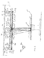
- the lighthead 1 along with its mounting supports 2; 21, 22; 21 1 , 21 2 , 22 1 , 22 2 and its frame 5, is disposed in the proximity of the operating theatre ceiling K above the operating table LP, as specifically illustrated in fig. 1 .
- the lighthead 1 is installed within an area defined by the incoming air frame TF and directly below this area. Consequently, the lighthead 1 is located below one or more air inlets TA of an incoming air duct TK, whereby the incoming air (arrows D in fig.
- the lighting system further comprises the control unit 8, fig. 4 , for adjusting at least the light elements 3 disposed on the light supports 2 of the lighthead 1.
- the control unit 8 comprises preferably at least three adjustment units 81, 82, 83.
- the first adjustment unit 81 is intended for managing the power supply to the light source 31 of each light element 2 and/or for adjusting the light intensity.
- the first adjustment unit 81 is connected to the light source 31 of each light element 3, particularly to its power supply V, for allowing and disrupting the power supply by way of the first adjustment unit 81 to the discussed light source, as well as for adjusting this power and thereby the light intensity within a predefined range.
- the light element 3 contains a number of LEDs, the spectral ranges of light produced thereby being different from each other, it is also possible to adjust the color temperature of light produced by the light element 3.
- the second adjustment unit 82 is intended for adjusting the optics 32 of each light element 3 and for concentrating a light beam 311 produced by the light element 3 at a desired distance. Hence, this enables the light beam 311 of each light element 3 to be focused e.g. on a specific level as regarded a.o. from the plane of an operating table.
- the second adjustment unit 82 is connected to an adjustment element for the optics 32 of each light element 3.
- the third adjustment unit 83 is intended for controlling alignment elements 33 for the light source 31 of each light element 3, such as one or more electric motors and a leverage or the like linked to the light element.
- alignment elements By means of the alignment elements, the light element 3 and at the same time the light beam 311 produced thereby can be tilted 10-15 degrees, most preferably in any direction, from an axis perpendicular to the level A-A (or B-B). Therefore, the light beam 311 produced by each light element 3 can be directed onto a predefined part of the operating table and particularly the surgical patient.
- the third adjustment unit 83 is used for controlling most preferably also a possible actuation of the light elements 3 in the mounting supports 2.
- the control unit 8 comprises preferably also a fourth adjustment unit 84, which is intended for controlling displacement elements 6, 7, such as one or more electric motors 61, for raising or lowering the frame 5.
- each electric motor is controlled so as to enable the attainment of a desired level for the lighthead 1 as determined e.g. from the floor level.
- the fourth control unit 84 is used for controlling most preferably also a possible shifting of the mounting supports 2; 21, 22 in the frame 5.
- the control unit 8 further comprises most preferably a plurality of sensors, which are connected to various adjustment units 81, 82, 83, 84 for obtaining measurement data about the lighting system for carrying out and monitoring the adjustment functions.
- the information obtained from the accessory 7; 71, 72 is utilized in the control unit 8 and, respectively, the accessories are operated and adjusted by means of the control unit.
- the control unit 8 further comprises one or more monitoring units 85, which are used for monitoring e.g. safety of the lighting system and for reporting possible malfunctions.
- the control unit 8 especially its adjustment and monitoring units 81, 82, 83, 84, 85, is used for monitoring and adjusting at least one of the following features of the light element 3: switching the light element on/off and the order of magnitude of its light intensity (and color temperature), setting the focus of a light beam and the direction of a light beam.
- switching the light element on/off and the order of magnitude of its light intensity (and color temperature) setting the focus of a light beam and the direction of a light beam.
- the control unit 8 along with its adjustment and monitoring units 81, 82, 83, 84, 85, is most preferably implemented by means of a microprocessor or the like data processing unit.
- the control unit 8 has its functions executed by means of computer programs and, thus, the lighting system operates in a program-controlled fashion.
- the lighting system comprises a remote controller 9.
- This is most preferably in a wireless (radio or infrared link) communication with the control unit 8, especially with its adjustment and monitoring units 81, 82, 83, 84, 85.
- the remote controller 9 is most preferably provided with a touch screen 91.
- Various symbols for functions of the lighting system and adjustable features of the light elements 2 are exhibitable on the touch screen.
Landscapes
- Health & Medical Sciences (AREA)
- Engineering & Computer Science (AREA)
- Surgery (AREA)
- Life Sciences & Earth Sciences (AREA)
- General Engineering & Computer Science (AREA)
- Medical Informatics (AREA)
- Public Health (AREA)
- Oral & Maxillofacial Surgery (AREA)
- Biomedical Technology (AREA)
- Heart & Thoracic Surgery (AREA)
- Nuclear Medicine, Radiotherapy & Molecular Imaging (AREA)
- Molecular Biology (AREA)
- Animal Behavior & Ethology (AREA)
- General Health & Medical Sciences (AREA)
- Pathology (AREA)
- Veterinary Medicine (AREA)
- Physics & Mathematics (AREA)
- Microelectronics & Electronic Packaging (AREA)
- Optics & Photonics (AREA)
- Arrangement Of Elements, Cooling, Sealing, Or The Like Of Lighting Devices (AREA)
- Non-Portable Lighting Devices Or Systems Thereof (AREA)
- Fastening Of Light Sources Or Lamp Holders (AREA)
Priority Applications (1)
| Application Number | Priority Date | Filing Date | Title |
|---|---|---|---|
| PL13151548T PL2618042T3 (pl) | 2012-01-17 | 2013-01-17 | Lepsza instalacja oświetleniowa sali operacyjnej |
Applications Claiming Priority (1)
| Application Number | Priority Date | Filing Date | Title |
|---|---|---|---|
| FI20125054A FI125372B (fi) | 2012-01-17 | 2012-01-17 | Parannettu leikkaussalin valaisinjärjestely |
Publications (3)
| Publication Number | Publication Date |
|---|---|
| EP2618042A2 true EP2618042A2 (de) | 2013-07-24 |
| EP2618042A3 EP2618042A3 (de) | 2014-02-19 |
| EP2618042B1 EP2618042B1 (de) | 2016-01-13 |
Family
ID=47552909
Family Applications (1)
| Application Number | Title | Priority Date | Filing Date |
|---|---|---|---|
| EP13151548.8A Not-in-force EP2618042B1 (de) | 2012-01-17 | 2013-01-17 | Vererbesserte Beleuchtungsanordnung für einenOperationssaal |
Country Status (4)
| Country | Link |
|---|---|
| EP (1) | EP2618042B1 (de) |
| EA (1) | EA024840B1 (de) |
| FI (1) | FI125372B (de) |
| PL (1) | PL2618042T3 (de) |
Cited By (7)
| Publication number | Priority date | Publication date | Assignee | Title |
|---|---|---|---|---|
| CN103629630A (zh) * | 2013-08-15 | 2014-03-12 | 温州市星际科技开发有限公司 | 聚泛可调灯头部件 |
| EP2951504A1 (de) * | 2013-01-30 | 2015-12-09 | Merivaara Oy | Beleuchtungsanordnung für einen operationssaal |
| EP3231390A1 (de) * | 2016-04-15 | 2017-10-18 | Merivaara Oy | Operationssaallampenkopf und verfahren zur präsentation von beleuchtungseinstellungsanweisungen an einen bediener des operationsraumbeleuchtungssystems |
| WO2019155426A1 (en) | 2018-02-09 | 2019-08-15 | Gentex Corporation | Adaptive lighting array with image-based control |
| CN111406180A (zh) * | 2018-11-02 | 2020-07-10 | 南京迈瑞生物医疗电子有限公司 | 手术室照明系统及其控制方法、装置及存储介质 |
| CN116592315A (zh) * | 2023-04-11 | 2023-08-15 | 南通溢德行工业科技有限公司 | 手术室净化用医用照明消毒灯 |
| US11994272B2 (en) | 2021-08-20 | 2024-05-28 | Gentex Corporation | Lighting assembly and illumination system having a lighting assembly |
Families Citing this family (1)
| Publication number | Priority date | Publication date | Assignee | Title |
|---|---|---|---|---|
| GB2630791A (en) * | 2023-06-08 | 2024-12-11 | Aspire Ise Ag | Modular air plenum unit |
Family Cites Families (9)
| Publication number | Priority date | Publication date | Assignee | Title |
|---|---|---|---|---|
| DE1810552B2 (de) * | 1968-11-23 | 1970-11-05 | Original Hanau Quarzlampen Gmbh, 6450 Hanau | Drehgelenk mit horizontaler Schwenkachse für über Federausgleich verbundene Schwenkarme, insbesondere von medizinischen Geräten |
| US5347431A (en) * | 1991-12-20 | 1994-09-13 | Blackwell Ray A | Lighting system and camera for operating room |
| DE20214879U1 (de) * | 2002-09-20 | 2003-10-30 | Arnold & Richter Cine Technik GmbH & Co Betriebs KG, 80799 München | Beleuchtungsvorrichtung |
| RU2233403C2 (ru) * | 2002-10-01 | 2004-07-27 | Зао "Вниимп-Вита" | Устройство для подвески медицинских светильников с пружинным компенсатором |
| FR2875892B1 (fr) * | 2004-09-29 | 2012-10-12 | Luxam Europ Soc | Systeme universel a fibres optiques pour eclairage de vitrines de musees |
| EP1741975B1 (de) * | 2005-07-05 | 2011-09-07 | Frowein EZH GmbH | Operationsleuchte |
| DE102006040393B4 (de) * | 2006-08-29 | 2018-11-22 | Dr. Mach Gmbh & Co. Kg | LED-Operationsleuchte |
| RU83314U1 (ru) * | 2008-12-30 | 2009-05-27 | Владимир Аликович Пак | Светильник |
| RU101528U1 (ru) * | 2010-08-06 | 2011-01-20 | Общество с ограниченной ответственностью "МиассСветоПрибор" | Светодиодный светильник |
-
2012
- 2012-01-17 FI FI20125054A patent/FI125372B/fi not_active IP Right Cessation
-
2013
- 2013-01-17 EP EP13151548.8A patent/EP2618042B1/de not_active Not-in-force
- 2013-01-17 PL PL13151548T patent/PL2618042T3/pl unknown
- 2013-01-17 EA EA201370002A patent/EA024840B1/ru not_active IP Right Cessation
Cited By (12)
| Publication number | Priority date | Publication date | Assignee | Title |
|---|---|---|---|---|
| EP2951504A1 (de) * | 2013-01-30 | 2015-12-09 | Merivaara Oy | Beleuchtungsanordnung für einen operationssaal |
| CN103629630A (zh) * | 2013-08-15 | 2014-03-12 | 温州市星际科技开发有限公司 | 聚泛可调灯头部件 |
| CN103629630B (zh) * | 2013-08-15 | 2017-05-17 | 温州市星际科技开发有限公司 | 聚泛可调灯头部件 |
| EP3231390A1 (de) * | 2016-04-15 | 2017-10-18 | Merivaara Oy | Operationssaallampenkopf und verfahren zur präsentation von beleuchtungseinstellungsanweisungen an einen bediener des operationsraumbeleuchtungssystems |
| WO2019155426A1 (en) | 2018-02-09 | 2019-08-15 | Gentex Corporation | Adaptive lighting array with image-based control |
| EP3750382A4 (de) * | 2018-02-09 | 2021-03-31 | Gentex Corporation | Adaptive beleuchtungsanordnung mit bildbasierter steuerung |
| CN111406180A (zh) * | 2018-11-02 | 2020-07-10 | 南京迈瑞生物医疗电子有限公司 | 手术室照明系统及其控制方法、装置及存储介质 |
| CN111406180B (zh) * | 2018-11-02 | 2023-04-28 | 南京迈瑞生物医疗电子有限公司 | 手术室照明系统及其控制方法、装置及存储介质 |
| US11994272B2 (en) | 2021-08-20 | 2024-05-28 | Gentex Corporation | Lighting assembly and illumination system having a lighting assembly |
| US12435864B2 (en) | 2021-08-20 | 2025-10-07 | Gentex Corporation | Lighting assembly and illumination system having a lighting assembly |
| CN116592315A (zh) * | 2023-04-11 | 2023-08-15 | 南通溢德行工业科技有限公司 | 手术室净化用医用照明消毒灯 |
| CN116592315B (zh) * | 2023-04-11 | 2024-03-26 | 南通溢德行工业科技有限公司 | 手术室净化用医用照明消毒灯 |
Also Published As
| Publication number | Publication date |
|---|---|
| EA201370002A1 (ru) | 2014-05-30 |
| EP2618042A3 (de) | 2014-02-19 |
| EP2618042B1 (de) | 2016-01-13 |
| PL2618042T3 (pl) | 2016-06-30 |
| FI20125054L (fi) | 2013-07-18 |
| FI125372B (fi) | 2015-09-15 |
| EA024840B1 (ru) | 2016-10-31 |
Similar Documents
| Publication | Publication Date | Title |
|---|---|---|
| EP2618042B1 (de) | Vererbesserte Beleuchtungsanordnung für einenOperationssaal | |
| FI126595B (fi) | Leikkaussalin valaisinjärjestely | |
| JP5911862B2 (ja) | ランプ | |
| JP4758660B2 (ja) | 手術用照明器具 | |
| US9119668B2 (en) | Surgical lamps and methods for illuminating operating sites | |
| EP3766306B1 (de) | Operationsleuchte mit operationslampenkopf mit beweglichen beleuchtungsmodulen | |
| US10240751B2 (en) | Systems and methods of illumination | |
| CN101608778A (zh) | 手术灯 | |
| AU2016361664B2 (en) | A lighting device | |
| US9228730B1 (en) | Variable radius multi-lamp illumination system | |
| US8331020B2 (en) | Illumination device for a microscope | |
| EP4044957B1 (de) | Flachbildschirmlichtmodul mit dynamischem strahl | |
| DE102010044353A1 (de) | Steh- oder Tischleuchte | |
| US12156312B2 (en) | Control for adaptive lighting array | |
| US10082280B2 (en) | Theatre light apparatus and method incorporating a plurality of light sources with anti-collision | |
| US8070322B2 (en) | Examination light with readily accessible controls | |
| CN103912814A (zh) | 一种手术灯 | |
| CN1908721B (zh) | 具有垂直照明装置的立体显微镜系统 | |
| US20200214788A1 (en) | Control apparatus and methods for adaptive lighting array | |
| WO2022181993A1 (ko) | 램프 | |
| US12366345B1 (en) | Light fixture with motor-driven shaping of output light | |
| JP4359408B2 (ja) | 照明灯 | |
| JP6713265B2 (ja) | バイオハザード対策用キャビネット | |
| GB2630791A (en) | Modular air plenum unit | |
| EP3480511A1 (de) | System zur beleuchtung einer umgebung |
Legal Events
| Date | Code | Title | Description |
|---|---|---|---|
| PUAI | Public reference made under article 153(3) epc to a published international application that has entered the european phase |
Free format text: ORIGINAL CODE: 0009012 |
|
| AK | Designated contracting states |
Kind code of ref document: A2 Designated state(s): AL AT BE BG CH CY CZ DE DK EE ES FI FR GB GR HR HU IE IS IT LI LT LU LV MC MK MT NL NO PL PT RO RS SE SI SK SM TR |
|
| AX | Request for extension of the european patent |
Extension state: BA ME |
|
| PUAL | Search report despatched |
Free format text: ORIGINAL CODE: 0009013 |
|
| AK | Designated contracting states |
Kind code of ref document: A3 Designated state(s): AL AT BE BG CH CY CZ DE DK EE ES FI FR GB GR HR HU IE IS IT LI LT LU LV MC MK MT NL NO PL PT RO RS SE SI SK SM TR |
|
| AX | Request for extension of the european patent |
Extension state: BA ME |
|
| RIC1 | Information provided on ipc code assigned before grant |
Ipc: F21V 21/15 20060101ALN20140110BHEP Ipc: F21W 131/205 20060101ALN20140110BHEP Ipc: F21V 21/34 20060101ALI20140110BHEP Ipc: F21S 2/00 20060101AFI20140110BHEP Ipc: F21Y 101/02 20060101ALN20140110BHEP Ipc: F21V 14/02 20060101ALN20140110BHEP |
|
| 17P | Request for examination filed |
Effective date: 20140818 |
|
| RBV | Designated contracting states (corrected) |
Designated state(s): AL AT BE BG CH CY CZ DE DK EE ES FI FR GB GR HR HU IE IS IT LI LT LU LV MC MK MT NL NO PL PT RO RS SE SI SK SM TR |
|
| 17Q | First examination report despatched |
Effective date: 20141001 |
|
| RIC1 | Information provided on ipc code assigned before grant |
Ipc: F21Y 101/02 20060101ALN20150430BHEP Ipc: F21V 21/15 20060101ALN20150430BHEP Ipc: F21V 21/34 20060101ALI20150430BHEP Ipc: A61B 19/00 20060101ALI20150430BHEP Ipc: F21W 131/205 20060101ALN20150430BHEP Ipc: F21V 14/02 20060101ALN20150430BHEP Ipc: F21S 2/00 20060101AFI20150430BHEP |
|
| GRAP | Despatch of communication of intention to grant a patent |
Free format text: ORIGINAL CODE: EPIDOSNIGR1 |
|
| INTG | Intention to grant announced |
Effective date: 20150722 |
|
| GRAS | Grant fee paid |
Free format text: ORIGINAL CODE: EPIDOSNIGR3 |
|
| GRAA | (expected) grant |
Free format text: ORIGINAL CODE: 0009210 |
|
| AK | Designated contracting states |
Kind code of ref document: B1 Designated state(s): AL AT BE BG CH CY CZ DE DK EE ES FI FR GB GR HR HU IE IS IT LI LT LU LV MC MK MT NL NO PL PT RO RS SE SI SK SM TR |
|
| REG | Reference to a national code |
Ref country code: GB Ref legal event code: FG4D |
|
| REG | Reference to a national code |
Ref country code: CH Ref legal event code: EP |
|
| REG | Reference to a national code |
Ref country code: IE Ref legal event code: FG4D |
|
| REG | Reference to a national code |
Ref country code: AT Ref legal event code: REF Ref document number: 770766 Country of ref document: AT Kind code of ref document: T Effective date: 20160215 |
|
| REG | Reference to a national code |
Ref country code: DE Ref legal event code: R096 Ref document number: 602013004548 Country of ref document: DE |
|
| REG | Reference to a national code |
Ref country code: FR Ref legal event code: PLFP Year of fee payment: 4 |
|
| REG | Reference to a national code |
Ref country code: SE Ref legal event code: TRGR |
|
| REG | Reference to a national code |
Ref country code: LT Ref legal event code: MG4D |
|
| REG | Reference to a national code |
Ref country code: NL Ref legal event code: MP Effective date: 20160113 |
|
| REG | Reference to a national code |
Ref country code: NO Ref legal event code: T2 Effective date: 20160113 |
|
| PG25 | Lapsed in a contracting state [announced via postgrant information from national office to epo] |
Ref country code: BE Free format text: LAPSE BECAUSE OF NON-PAYMENT OF DUE FEES Effective date: 20160131 |
|
| REG | Reference to a national code |
Ref country code: AT Ref legal event code: MK05 Ref document number: 770766 Country of ref document: AT Kind code of ref document: T Effective date: 20160113 |
|
| PG25 | Lapsed in a contracting state [announced via postgrant information from national office to epo] |
Ref country code: NL Free format text: LAPSE BECAUSE OF FAILURE TO SUBMIT A TRANSLATION OF THE DESCRIPTION OR TO PAY THE FEE WITHIN THE PRESCRIBED TIME-LIMIT Effective date: 20160113 |
|
| PG25 | Lapsed in a contracting state [announced via postgrant information from national office to epo] |
Ref country code: ES Free format text: LAPSE BECAUSE OF FAILURE TO SUBMIT A TRANSLATION OF THE DESCRIPTION OR TO PAY THE FEE WITHIN THE PRESCRIBED TIME-LIMIT Effective date: 20160113 Ref country code: HR Free format text: LAPSE BECAUSE OF FAILURE TO SUBMIT A TRANSLATION OF THE DESCRIPTION OR TO PAY THE FEE WITHIN THE PRESCRIBED TIME-LIMIT Effective date: 20160113 Ref country code: GR Free format text: LAPSE BECAUSE OF FAILURE TO SUBMIT A TRANSLATION OF THE DESCRIPTION OR TO PAY THE FEE WITHIN THE PRESCRIBED TIME-LIMIT Effective date: 20160414 |
|
| PG25 | Lapsed in a contracting state [announced via postgrant information from national office to epo] |
Ref country code: AT Free format text: LAPSE BECAUSE OF FAILURE TO SUBMIT A TRANSLATION OF THE DESCRIPTION OR TO PAY THE FEE WITHIN THE PRESCRIBED TIME-LIMIT Effective date: 20160113 Ref country code: IS Free format text: LAPSE BECAUSE OF FAILURE TO SUBMIT A TRANSLATION OF THE DESCRIPTION OR TO PAY THE FEE WITHIN THE PRESCRIBED TIME-LIMIT Effective date: 20160513 Ref country code: RS Free format text: LAPSE BECAUSE OF FAILURE TO SUBMIT A TRANSLATION OF THE DESCRIPTION OR TO PAY THE FEE WITHIN THE PRESCRIBED TIME-LIMIT Effective date: 20160113 Ref country code: LT Free format text: LAPSE BECAUSE OF FAILURE TO SUBMIT A TRANSLATION OF THE DESCRIPTION OR TO PAY THE FEE WITHIN THE PRESCRIBED TIME-LIMIT Effective date: 20160113 Ref country code: PT Free format text: LAPSE BECAUSE OF FAILURE TO SUBMIT A TRANSLATION OF THE DESCRIPTION OR TO PAY THE FEE WITHIN THE PRESCRIBED TIME-LIMIT Effective date: 20160513 Ref country code: LV Free format text: LAPSE BECAUSE OF FAILURE TO SUBMIT A TRANSLATION OF THE DESCRIPTION OR TO PAY THE FEE WITHIN THE PRESCRIBED TIME-LIMIT Effective date: 20160113 |
|
| REG | Reference to a national code |
Ref country code: CH Ref legal event code: PL |
|
| REG | Reference to a national code |
Ref country code: DE Ref legal event code: R097 Ref document number: 602013004548 Country of ref document: DE |
|
| PG25 | Lapsed in a contracting state [announced via postgrant information from national office to epo] |
Ref country code: CH Free format text: LAPSE BECAUSE OF NON-PAYMENT OF DUE FEES Effective date: 20160131 Ref country code: DK Free format text: LAPSE BECAUSE OF FAILURE TO SUBMIT A TRANSLATION OF THE DESCRIPTION OR TO PAY THE FEE WITHIN THE PRESCRIBED TIME-LIMIT Effective date: 20160113 Ref country code: LI Free format text: LAPSE BECAUSE OF NON-PAYMENT OF DUE FEES Effective date: 20160131 Ref country code: MC Free format text: LAPSE BECAUSE OF FAILURE TO SUBMIT A TRANSLATION OF THE DESCRIPTION OR TO PAY THE FEE WITHIN THE PRESCRIBED TIME-LIMIT Effective date: 20160113 Ref country code: EE Free format text: LAPSE BECAUSE OF FAILURE TO SUBMIT A TRANSLATION OF THE DESCRIPTION OR TO PAY THE FEE WITHIN THE PRESCRIBED TIME-LIMIT Effective date: 20160113 |
|
| REG | Reference to a national code |
Ref country code: IE Ref legal event code: MM4A |
|
| PLBE | No opposition filed within time limit |
Free format text: ORIGINAL CODE: 0009261 |
|
| STAA | Information on the status of an ep patent application or granted ep patent |
Free format text: STATUS: NO OPPOSITION FILED WITHIN TIME LIMIT |
|
| PG25 | Lapsed in a contracting state [announced via postgrant information from national office to epo] |
Ref country code: RO Free format text: LAPSE BECAUSE OF FAILURE TO SUBMIT A TRANSLATION OF THE DESCRIPTION OR TO PAY THE FEE WITHIN THE PRESCRIBED TIME-LIMIT Effective date: 20160113 Ref country code: SM Free format text: LAPSE BECAUSE OF FAILURE TO SUBMIT A TRANSLATION OF THE DESCRIPTION OR TO PAY THE FEE WITHIN THE PRESCRIBED TIME-LIMIT Effective date: 20160113 Ref country code: SK Free format text: LAPSE BECAUSE OF FAILURE TO SUBMIT A TRANSLATION OF THE DESCRIPTION OR TO PAY THE FEE WITHIN THE PRESCRIBED TIME-LIMIT Effective date: 20160113 |
|
| 26N | No opposition filed |
Effective date: 20161014 |
|
| PG25 | Lapsed in a contracting state [announced via postgrant information from national office to epo] |
Ref country code: BE Free format text: LAPSE BECAUSE OF FAILURE TO SUBMIT A TRANSLATION OF THE DESCRIPTION OR TO PAY THE FEE WITHIN THE PRESCRIBED TIME-LIMIT Effective date: 20160113 |
|
| REG | Reference to a national code |
Ref country code: FR Ref legal event code: PLFP Year of fee payment: 5 |
|
| PG25 | Lapsed in a contracting state [announced via postgrant information from national office to epo] |
Ref country code: IE Free format text: LAPSE BECAUSE OF NON-PAYMENT OF DUE FEES Effective date: 20160117 |
|
| PG25 | Lapsed in a contracting state [announced via postgrant information from national office to epo] |
Ref country code: BG Free format text: LAPSE BECAUSE OF FAILURE TO SUBMIT A TRANSLATION OF THE DESCRIPTION OR TO PAY THE FEE WITHIN THE PRESCRIBED TIME-LIMIT Effective date: 20160413 Ref country code: SI Free format text: LAPSE BECAUSE OF FAILURE TO SUBMIT A TRANSLATION OF THE DESCRIPTION OR TO PAY THE FEE WITHIN THE PRESCRIBED TIME-LIMIT Effective date: 20160113 |
|
| PG25 | Lapsed in a contracting state [announced via postgrant information from national office to epo] |
Ref country code: MT Free format text: LAPSE BECAUSE OF FAILURE TO SUBMIT A TRANSLATION OF THE DESCRIPTION OR TO PAY THE FEE WITHIN THE PRESCRIBED TIME-LIMIT Effective date: 20160113 |
|
| REG | Reference to a national code |
Ref country code: FR Ref legal event code: PLFP Year of fee payment: 6 |
|
| PGFP | Annual fee paid to national office [announced via postgrant information from national office to epo] |
Ref country code: PL Payment date: 20171220 Year of fee payment: 6 |
|
| PGFP | Annual fee paid to national office [announced via postgrant information from national office to epo] |
Ref country code: CZ Payment date: 20180104 Year of fee payment: 6 Ref country code: DE Payment date: 20180116 Year of fee payment: 6 |
|
| PG25 | Lapsed in a contracting state [announced via postgrant information from national office to epo] |
Ref country code: CY Free format text: LAPSE BECAUSE OF FAILURE TO SUBMIT A TRANSLATION OF THE DESCRIPTION OR TO PAY THE FEE WITHIN THE PRESCRIBED TIME-LIMIT Effective date: 20160113 Ref country code: HU Free format text: LAPSE BECAUSE OF FAILURE TO SUBMIT A TRANSLATION OF THE DESCRIPTION OR TO PAY THE FEE WITHIN THE PRESCRIBED TIME-LIMIT; INVALID AB INITIO Effective date: 20130117 |
|
| PGFP | Annual fee paid to national office [announced via postgrant information from national office to epo] |
Ref country code: TR Payment date: 20180111 Year of fee payment: 6 Ref country code: FR Payment date: 20180116 Year of fee payment: 6 Ref country code: IT Payment date: 20180122 Year of fee payment: 6 |
|
| PG25 | Lapsed in a contracting state [announced via postgrant information from national office to epo] |
Ref country code: MT Free format text: LAPSE BECAUSE OF FAILURE TO SUBMIT A TRANSLATION OF THE DESCRIPTION OR TO PAY THE FEE WITHIN THE PRESCRIBED TIME-LIMIT Effective date: 20160131 Ref country code: LU Free format text: LAPSE BECAUSE OF NON-PAYMENT OF DUE FEES Effective date: 20160117 Ref country code: MK Free format text: LAPSE BECAUSE OF FAILURE TO SUBMIT A TRANSLATION OF THE DESCRIPTION OR TO PAY THE FEE WITHIN THE PRESCRIBED TIME-LIMIT Effective date: 20160113 |
|
| PG25 | Lapsed in a contracting state [announced via postgrant information from national office to epo] |
Ref country code: AL Free format text: LAPSE BECAUSE OF FAILURE TO SUBMIT A TRANSLATION OF THE DESCRIPTION OR TO PAY THE FEE WITHIN THE PRESCRIBED TIME-LIMIT Effective date: 20160113 |
|
| RIC2 | Information provided on ipc code assigned after grant |
Ipc: F21V 21/34 20060101ALI20150430BHEP Ipc: F21V 21/15 20060101ALN20150430BHEP Ipc: A61B 19/00 20060101ALI20150430BHEP Ipc: F21Y 101/02 20000101ALN20150430BHEP Ipc: F21W 131/205 20060101ALN20150430BHEP Ipc: F21V 14/02 20060101ALN20150430BHEP Ipc: F21S 2/00 20160101AFI20150430BHEP |
|
| PGFP | Annual fee paid to national office [announced via postgrant information from national office to epo] |
Ref country code: GB Payment date: 20190115 Year of fee payment: 7 Ref country code: NO Payment date: 20190117 Year of fee payment: 7 Ref country code: FI Payment date: 20190118 Year of fee payment: 7 |
|
| PGFP | Annual fee paid to national office [announced via postgrant information from national office to epo] |
Ref country code: SE Payment date: 20190116 Year of fee payment: 7 |
|
| REG | Reference to a national code |
Ref country code: DE Ref legal event code: R119 Ref document number: 602013004548 Country of ref document: DE |
|
| PG25 | Lapsed in a contracting state [announced via postgrant information from national office to epo] |
Ref country code: FR Free format text: LAPSE BECAUSE OF NON-PAYMENT OF DUE FEES Effective date: 20190131 Ref country code: CZ Free format text: LAPSE BECAUSE OF NON-PAYMENT OF DUE FEES Effective date: 20190117 Ref country code: DE Free format text: LAPSE BECAUSE OF NON-PAYMENT OF DUE FEES Effective date: 20190801 |
|
| PG25 | Lapsed in a contracting state [announced via postgrant information from national office to epo] |
Ref country code: IT Free format text: LAPSE BECAUSE OF NON-PAYMENT OF DUE FEES Effective date: 20190117 |
|
| REG | Reference to a national code |
Ref country code: FI Ref legal event code: MAE |
|
| REG | Reference to a national code |
Ref country code: NO Ref legal event code: MMEP |
|
| PG25 | Lapsed in a contracting state [announced via postgrant information from national office to epo] |
Ref country code: PL Free format text: LAPSE BECAUSE OF NON-PAYMENT OF DUE FEES Effective date: 20190117 |
|
| REG | Reference to a national code |
Ref country code: SE Ref legal event code: EUG |
|
| GBPC | Gb: european patent ceased through non-payment of renewal fee |
Effective date: 20200117 |
|
| REG | Reference to a national code |
Ref country code: SE Ref legal event code: EUG |
|
| PG25 | Lapsed in a contracting state [announced via postgrant information from national office to epo] |
Ref country code: FI Free format text: LAPSE BECAUSE OF NON-PAYMENT OF DUE FEES Effective date: 20200117 Ref country code: GB Free format text: LAPSE BECAUSE OF NON-PAYMENT OF DUE FEES Effective date: 20200117 Ref country code: NO Free format text: LAPSE BECAUSE OF NON-PAYMENT OF DUE FEES Effective date: 20200131 Ref country code: SE Free format text: LAPSE BECAUSE OF NON-PAYMENT OF DUE FEES Effective date: 20200118 |
|
| PG25 | Lapsed in a contracting state [announced via postgrant information from national office to epo] |
Ref country code: TR Free format text: LAPSE BECAUSE OF NON-PAYMENT OF DUE FEES Effective date: 20190117 |