EP2617807A1 - Culture substrate - Google Patents
Culture substrate Download PDFInfo
- Publication number
- EP2617807A1 EP2617807A1 EP11825017.4A EP11825017A EP2617807A1 EP 2617807 A1 EP2617807 A1 EP 2617807A1 EP 11825017 A EP11825017 A EP 11825017A EP 2617807 A1 EP2617807 A1 EP 2617807A1
- Authority
- EP
- European Patent Office
- Prior art keywords
- culture substrate
- dents
- culture
- cultured
- cells
- Prior art date
- Legal status (The legal status is an assumption and is not a legal conclusion. Google has not performed a legal analysis and makes no representation as to the accuracy of the status listed.)
- Granted
Links
Images


Classifications
-
- C—CHEMISTRY; METALLURGY
- C12—BIOCHEMISTRY; BEER; SPIRITS; WINE; VINEGAR; MICROBIOLOGY; ENZYMOLOGY; MUTATION OR GENETIC ENGINEERING
- C12M—APPARATUS FOR ENZYMOLOGY OR MICROBIOLOGY; APPARATUS FOR CULTURING MICROORGANISMS FOR PRODUCING BIOMASS, FOR GROWING CELLS OR FOR OBTAINING FERMENTATION OR METABOLIC PRODUCTS, i.e. BIOREACTORS OR FERMENTERS
- C12M23/00—Constructional details, e.g. recesses, hinges
- C12M23/02—Form or structure of the vessel
- C12M23/12—Well or multiwell plates
-
- C—CHEMISTRY; METALLURGY
- C12—BIOCHEMISTRY; BEER; SPIRITS; WINE; VINEGAR; MICROBIOLOGY; ENZYMOLOGY; MUTATION OR GENETIC ENGINEERING
- C12M—APPARATUS FOR ENZYMOLOGY OR MICROBIOLOGY; APPARATUS FOR CULTURING MICROORGANISMS FOR PRODUCING BIOMASS, FOR GROWING CELLS OR FOR OBTAINING FERMENTATION OR METABOLIC PRODUCTS, i.e. BIOREACTORS OR FERMENTERS
- C12M23/00—Constructional details, e.g. recesses, hinges
- C12M23/02—Form or structure of the vessel
- C12M23/10—Petri dish
Definitions
- the present invention relates to a culture substrate to culture objects to be cultured such as cells and tissues thereby to prepare spheroids.
- a container as shown in Fig. 11 may be mentioned.
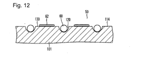
- a plurality of dents 120 are formed with intervals therebetween, as shown in Fig. 12 .
- the bottom 114 of the container is coated with a cell adhesion inhibitor (not shown) (Patent Document 1).
- a culture fluid 50 in which cells as spheroid precursors are stirred is poured into the culture container, and the cells are cultured in the dents 120.
- the cells in the dents 120 are cultured in accordance with the shape and the size of the dents 120, are aggregated three-dimensionally and form spheroids 60 as shown in Fig. 12 .
- Patent Document 1 WO2007/055056
- cells may be two-dimensionally cultured, or spheroids in random sizes which are unaffected by the size of the dents may form.
- culturing to uniformly form spheroids having a desired size cannot efficiently be carried out.
- These cells cultured in monolayer or spheroids in random sizes may have different physiological functions, or in a case of stem cell culturing, may be in a different stage of differentiation as compared with uniform spheroids in accordance with the size of the dents.
- the uniformity of the cell groups in the culture container tends to be low, thus impairing the evaluation of experimental data, etc.
- the present invention has been made to solve the above problems, and its object is to provide a culture substrate with which spheroids having a desired size can be uniformly formed, and culturing can efficiently be carried out.
- the culture substrate of the present invention is characterized by having a plurality of dents to form compartments in which objects to be cultured are cultured, on the culture substrate surface, the culture substrate surface between adjacent dents being a non-flat surface.
- spheroid culturing can efficiently be carried out.
- a culture substrate according to a first embodiment of the present invention will be described with reference to Figs. 1 to 6 .
- Fig. 1 is an oblique view illustrating a culture container having a culture substrate of the present invention.
- Fig. 2 is a vertical cross sectional view illustrating a culture container.
- Fig. 3 is a partial oblique view illustrating a well-forming region of a culture substrate.
- Fig. 4 is a cross sectional view at the arrow IV-IV of Fig. 3.
- Fig. 5 is a cross sectional view at the arrow V-V of Fig. 3 .
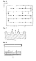
- Fig. 6 is a plan view illustrating irradiation spots with laser light applied to the surface of a culture substrate.
- the culture substrate 1 constitutes a main portion of a culture container to prepare spheroids (cell aggregates) by culturing cells and three-dimensionally aggregating them.
- a culture container has a container main body 10 and a lid 12 as shown in Figs. 1 and 2 .
- a baseplate portion 14 in the inside of the container main body 10 is a portion corresponding to the culture substrate 1.
- the baseplate portion 14 in the inside of the container main body 10, i.e. the culture substrate 1 is made of a synthetic resin, for example, polystyrene.
- the culture substrate 1 is obtained by injection molding using a synthetic resin material.
- the container main body 10 has a disk-shape baseplate portion 14 and a cyclic side wall portion 16.
- the side wall portion 16 stands up from the periphery of the baseplate portion 14.
- the baseplate portion 14 is designed to have a diameter of 85 mm and a thickness of 1 mm.
- the side wall portion 16 is designed to have a height of 20 mm.
- the lid 12 is formed into a shape corresponding to an opening of the container main body 10.
- the lid 12 is used to cover the container main body 10 so as to maintain the cell culture environment.
- a well-forming region 24 (that is, a region on which compartments in which objects to be cultured are cultured are formed) on the upper surface of the baseplate portion 14 (that is, the upper surface of the culture substrate corresponding to the surface in the inside of the container main body 10), a plurality of dents 20 are formed as shown in Figs. 2 to 5 .
- the inner surface of each dent 20 is a smooth concave plane.
- Each dent 20 forms a compartment (well) in which objects to be cultured are cultured.
- a circular well-forming region 24 having a diameter of 85 mm about 14,200 dents (about 250 dents/cm 2 ) 20 are formed.
- the dents 20 are formed by irradiating the well-forming region 24 on the culture substrate surface with laser light.
- the laser irradiation is carried out by irradiating the upper surface of the baseplate portion 14 placed in an x-y plane with laser light in a z axis direction as shown in Fig. 6 .
- laser light is applied at certain intervals (for example, 800 ⁇ m) to form an array of a plurality of dents 20 in the x axis direction. Then, the irradiation portion is moved in the y axis direction for a certain distance (for example, 400 ⁇ m), and then while the irradiation portion is moved in a negative direction of the x axis, laser light is applied at certain intervals (for example 800 ⁇ m) to form an array of a plurality of dents 20 in the x axis direction.
- the irradiation portion is moved in the y axis direction for a certain distance (for example, 400 ⁇ m). These operations are repeatedly carried out to form a plurality of dents regularly aligned on the upper surface of the baseplate portion 14.
- the central coordinate (x, y) of the irradiation spot A is the origin (0, 0)
- the center of the irradiation spot B adjacent to the irradiation spot A is located at (0.8, 0)
- the center of the irradiation spot C is located at (0.4, 0.4)
- the center of the irradiation spot D is located at (-0.4, 0.4).
- a plurality of dents 20 can be densely formed on the well-forming region 24.
- the dents 20 are formed preferably in a density of from 10 dents/cm 2 to 10,000 dents/cm 2 per unit area of the well-forming region 24 of the culture substrate 1, more preferably from 20 dents/cm 2 to 8,000 dents/cm 2 , further preferably from 20 dents/cm 2 to 3,000 dents/cm 2 .
- a CO 2 laser is used as a laser light source, and the laser light is applied by pulse irradiation at an output power of 10 W at an irradiation rate of 6,100 mm/min.
- the shape of the irradiation spot is circular, and its diameter is about 400 ⁇ m. If the spheroids are too small, no desired physiological function will be obtained, and if they are too large, the central portions of the spheroids undergo necrosis. Considering these points, the diameter of the irradiation spot is appropriately from 20 to 1,500 ⁇ m.
- the shape of the irradiation spot is circular
- the shape of the opening of each dent 20 is flattened into a substantially elliptical shape. This flatness of the opening shape is considered to be attributable to the direction in which the synthetic resin material is poured into a mold at the time of molding the container main body 10.
- the synthetic resin material constituting the baseplate portion 14 is melted, whereby dents 20 are formed. Further, at the peripheries of the openings of the dents 20, the molten synthetic resin material is piled up to form banks 22 as shown in Figs. 3 to 5 .
- the two adjacent dents 20 are formed via one or two banks 22, and on the culture substrate surface between adjacent dents 20, no flat surface remains. That is, the culture substrate surface between adjacent dents 20 forms a non-flat surface 30.
- two banks 22 present between two adjacent dents 20 are connected to each other to form the non-flat surface 30.
- the distance between adjacent dents 20, the diameter and the depth of each dent 20, the width and the height of each bank 22 and the like can be adjusted by adjusting the irradiation conditions such as the laser light irradiation position and the output power.
- laser irradiation is carried out by setting the laser light irradiation conditions so that no flat surface remains on the culture substrate surface between adjacent dents 20, that is, the culture substrate surface between adjacent dents 20 is the non-flat surface 30.
- each dent 20 is preferably designed to be from 10 to 1,500 ⁇ m, and in this embodiment, it is designed to be 200 ⁇ 20 ⁇ m. Further, the thickness of the baseplate portion 14 is properly designed depending upon the depth d so that the baseplate portion 14 will not have a hole.
- each substantially elliptic dent 20 is preferably designed to be from 10 to 1,500 ⁇ m, and in this embodiment, it is designed to be 500 ⁇ 20 ⁇ m.
- the height (i.e. the height based on the upper surface of the baseplate portion 14 before laser irradiation as shown in Figs. 4 and 5 ) h of each bank 22 is preferably designed to be from 10 to 50 ⁇ m, and in this embodiment, it is designed to be 25 ⁇ 5 ⁇ m.
- the culture substrate cell adhesion inhibitor has a role to inhibit cells from adhering to the upper surface of the baseplate portion 14, particularly the inner surfaces of the dents 20.
- a phospholipid polymer, polyhydroxyethyl methacrylate or polyethylene glycol may, for example, be used.
- Cells as spheroid precursors which are objects to be cultured are put in a culture fluid 50 and stirred. After stirring, the culture fluid 50 is poured into a container main body 10 (see Fig. 2 ), whereupon the cells in the culture fluid 50 precipitate and fit into dents 20.
- the container main body 10 is covered with a lid 12 and is left to stand for several days to several tens days.
- the cells in the dents 20 are cultured and grow.
- the inner surfaces of the dents 20 are coated with the cell adhesion inhibitor, the cells three-dimensionally aggregate in accordance with the shape and the size of the dents 20. In such a manner, spheroids are obtained.
- the culture substrate surface between adjacent dents 20 is the non-flat surface 30. Accordingly, the precipitating objects to be cultured are likely to fit into the dents 20.
- a conventional culture substrate 101 flat surfaces 130 are formed on the culture substrate surface between adjacent dents 120. Accordingly, on the flat surfaces 130, cells may be cultured in monolayer, or spheroids in random sizes which are unaffected by the size of the dents 120 may form.
- the culture substrate surface between adjacent dents 20 forms a non-flat surface 30. Accordingly, cells are less likely to be cultured in monolayer, or non-uniform spheroids are less likely to form, the probability of uniform spheroids forming is high, and the spheroid culturing can efficiently be carried out.
- the size of the spheroids to be prepared varies depending upon the purpose of use of the spheroids, the type of cells to be cultured, and the like. Accordingly, to prepare spheroids, it is necessary to prepare a culture substrate 1 having dents 20 in accordance with the desired size of spheroids.
- the dents 20 and the banks 22 are formed by laser irradiation. Accordingly, by adjusting the irradiation conditions such as the irradiation position and the output power, it is possible to easily form dents 20 and banks 22 having optional sizes on the culture substrate 1.
- the dents 20 open upward in their cross section, and the inner surfaces of the dents 20 are smooth by heat of the laser light, thus reducing diffuse reflection of transmitted light, whereby the spheroids to be cultured in the dents 20 can easily be observed by a microscope.
- FIG. 7 is a partial cross sectional view illustrating a well-forming region of a culture substrate.
- This embodiment is a modified example of the first embodiment, and for the same components and the analogous components in the first embodiment, the same symbols are used, and duplicated explanation will be omitted.
- a plurality of dents 20 and banks 22 are formed by irradiating the culture substrate surface with laser light.
- the culture substrate 1 is formed by injection molding a synthetic resin material using a mold having convexes to form a plurality of dents 20 and concaves to form banks 22.
- the plurality of dents 20 and banks 22 are formed simultaneously with molding of the culture substrate 1.
- hemispherical dents 20 and banks 22 which are semi-circular in their cross section are formed.
- FIG. 8 is a vertical cross sectional view illustrating a state where a culture substrate is placed in a petri dish.
- This embodiment is a modified example of the first embodiment, and for the same components and the analogous components in the first embodiment, the same symbols are used, and duplicated explanation will be omitted.
- a culture substrate 1 In the culture substrate 1 according to the first embodiment, a plurality of dents 20 are formed on the bottom (the upper surface of the baseplate portion 14) in the inside of the culture container.
- a culture substrate 1 according to this embodiment comprises a synthetic resin material formed into a disk shape. The culture substrate 1 is formed in such a manner that a synthetic resin material is injection molded into a disk-shape substrate, and one surface is irradiated with laser light to form a plurality of dents 20 on the one surface of the culture substrate 1.
- the culture substrate 1 according to this embodiment is used as placed in a petri dish 40 made of glass for example, as shown in Fig. 8 . According to this embodiment, formation of the culture substrate 1 is easy, and the production cost can be suppressed, as compared with the first embodiment.
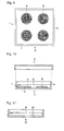
- FIG. 9 is a plan view illustrating a culture substrate.
- Fig. 10 is a vertical cross sectional view illustrating a culture container having a container main body provided with a culture substrate and a lid.
- This embodiment is a modified example of the first embodiment, and for the same components and the analogous components in the first embodiment, the same symbols are used, and duplicated explanation will be omitted.
- a baseplate portion 14 of a container main body 10 corresponds as shown in Fig. 9 , and on the upper surface of the baseplate portion 14, there are four circular well-forming regions 24.
- the four well-forming regions 24 are disposed with distances therebetween.
- a plurality of dents to form compartments in which objects to be cultured are cultured are formed on the substrate surface, and the substrate surface between adjacent dents forms a non-flat surface.
- cells as spheroid precursors are put by using a pipet or the like, and a stirred culture fluid 50 or a culture fluid 50 containing fertilized eggs is dropped on the four well-forming regions 24. Then, as shown in Fig. 10 , mineral oil 52 is poured into the container main body 10. On that occasion, the culture fluid 50 and the mineral oil 52 are not miscible. In such a state, the container is left to stand for several days to several tens days to prepare spheroids or to culture the fertilized eggs.
- the material of the culture substrate 1 may be glass, not a synthetic resin material.
- the shape and the size of the culture substrate 1 may optionally be designed.
- the shape and the size of the dents 20 and the banks 22 may also be optionally designed depending upon the shape and the size of cells to be cultured or desired spheroids.
- the above embodiments may be combined.
- the dents 20 on the disk-shape culture substrate 1 according to the third embodiment may be formed by injection molding as described for the second embodiment.
- the culture substrate surface between adjacent dents is a non-flat surface
- precipitating objects to be cultured are likely to fit into the dents
- the culture substrate surface is the non-flat surface
- two dimensional culturing in monolayer or formation of non-uniform spheroids is less likely to occur, the probability of three-dimensionally uniformly aggregated spheroids forming is high, and spheroid culturing can efficiently be carried out.
Landscapes
- Health & Medical Sciences (AREA)
- Organic Chemistry (AREA)
- Life Sciences & Earth Sciences (AREA)
- Engineering & Computer Science (AREA)
- Bioinformatics & Cheminformatics (AREA)
- Chemical & Material Sciences (AREA)
- Zoology (AREA)
- Wood Science & Technology (AREA)
- Sustainable Development (AREA)
- Microbiology (AREA)
- Biotechnology (AREA)
- Biomedical Technology (AREA)
- Biochemistry (AREA)
- General Engineering & Computer Science (AREA)
- General Health & Medical Sciences (AREA)
- Genetics & Genomics (AREA)
- Clinical Laboratory Science (AREA)
- Apparatus Associated With Microorganisms And Enzymes (AREA)
Abstract
Description
- The present invention relates to a culture substrate to culture objects to be cultured such as cells and tissues thereby to prepare spheroids.
- In recent years, instead of monolayer culturing to two-dimensionally culture cells, spheroid culturing to culture cells and three-dimensionally aggregate them has attracted attention. By the spheroid culturing, cells in a state closer to cells in the body can be constituted as compared with the monolayer culturing, and specific functions which cells have in the body can be brought out.
- As one example of a
conventional culture substrate 101 to carry out the spheroid culturing, for example, a container as shown inFig. 11 may be mentioned. At thebottom 114 of this container, a plurality ofdents 120 are formed with intervals therebetween, as shown inFig. 12 . Thebottom 114 of the container is coated with a cell adhesion inhibitor (not shown) (Patent Document 1). - By the spheroid culturing, a
culture fluid 50 in which cells as spheroid precursors are stirred is poured into the culture container, and the cells are cultured in thedents 120. The cells in thedents 120 are cultured in accordance with the shape and the size of thedents 120, are aggregated three-dimensionally and formspheroids 60 as shown inFig. 12 . - Patent Document 1:
WO2007/055056 - However, if spheroid culturing is carried out by using the above-described
conventional culture substrate 101, there have been such problems thatcells 62 cultured in monolayer and spheroids with non-uniform sizes are formed in a large amount in addition to thespheroids 60. The reason is considered to be such that in theconventional culture substrate 101, as shown inFig. 12 ,flat surfaces 130 are formed on the substrate surface betweenadjacent dents 120. In a case where theflat surfaces 130 are formed like this case, if aculture fluid 50 in which cells are stirred is poured into the culture container, cells are precipitated even on theflat surfaces 130. If such cells are present in the culture container, in addition tospheroids 60 in accordance with the size of the dents, cells may be two-dimensionally cultured, or spheroids in random sizes which are unaffected by the size of the dents may form. As mentioned above, with theconventional culture substrate 101, culturing to uniformly form spheroids having a desired size cannot efficiently be carried out. These cells cultured in monolayer or spheroids in random sizes may have different physiological functions, or in a case of stem cell culturing, may be in a different stage of differentiation as compared with uniform spheroids in accordance with the size of the dents. Thus, the uniformity of the cell groups in the culture container tends to be low, thus impairing the evaluation of experimental data, etc. - Under these circumstances, the present invention has been made to solve the above problems, and its object is to provide a culture substrate with which spheroids having a desired size can be uniformly formed, and culturing can efficiently be carried out.
- To achieve the above object, the culture substrate of the present invention is characterized by having a plurality of dents to form compartments in which objects to be cultured are cultured, on the culture substrate surface, the culture substrate surface between adjacent dents being a non-flat surface.
- According to the present invention, spheroid culturing can efficiently be carried out.
-
-
Fig. 1 is an oblique view illustrating a culture substrate according to a first embodiment of the present invention. -
Fig. 2 is a vertical cross sectional view illustrating a culture substrate according to a first embodiment of the present invention. -
Fig. 3 is a partial oblique view illustrating a well-forming region of a culture substrate according to a first embodiment of the present invention. -
Fig. 4 is a cross sectional view at the arrow IV-IV ofFig. 3 . -
Fig. 5 is a cross sectional view at the arrow V-V ofFig. 3 . -
Fig. 6 is a plan view schematically illustrating irradiation spots with laser light on the surface of a culture substrate according to a first embodiment of the present invention. -
Fig. 7 is a partial cross sectional view illustrating a well-forming region of a culture substrate according to a second embodiment of the present invention. -
Fig. 8 is a vertical cross sectional view illustrating a state where a culture substrate according to a third embodiment of the present invention is placed in a petri dish. -
Fig. 9 is a plan view illustrating a culture substrate according to a fourth embodiment of the present invention. -
Fig. 10 is a vertical cross sectional view illustrating a culture substrate according to a fourth embodiment of the present invention. -
Fig. 11 is a cross sectional view illustrating a conventional culture substrate. -
Fig. 12 is a cross sectional view schematically illustrating objects to be cultured on the surface of a conventional culture substrate. - A culture substrate according to a first embodiment of the present invention will be described with reference to
Figs. 1 to 6 . -
Fig. 1 is an oblique view illustrating a culture container having a culture substrate of the present invention.Fig. 2 is a vertical cross sectional view illustrating a culture container.Fig. 3 is a partial oblique view illustrating a well-forming region of a culture substrate.Fig. 4 is a cross sectional view at the arrow IV-IV ofFig. 3. Fig. 5 is a cross sectional view at the arrow V-V ofFig. 3 .Fig. 6 is a plan view illustrating irradiation spots with laser light applied to the surface of a culture substrate. - The
culture substrate 1 according to this embodiment constitutes a main portion of a culture container to prepare spheroids (cell aggregates) by culturing cells and three-dimensionally aggregating them. - First, the constitution of the
culture substrate 1 according to this embodiment will be described. - A culture container has a container
main body 10 and alid 12 as shown inFigs. 1 and 2 . In this example, abaseplate portion 14 in the inside of the containermain body 10 is a portion corresponding to theculture substrate 1. Thebaseplate portion 14 in the inside of the containermain body 10, i.e. theculture substrate 1, is made of a synthetic resin, for example, polystyrene. In this embodiment, theculture substrate 1 is obtained by injection molding using a synthetic resin material. - The container
main body 10 has a disk-shape baseplate portion 14 and a cyclicside wall portion 16. Theside wall portion 16 stands up from the periphery of thebaseplate portion 14. In this embodiment, thebaseplate portion 14 is designed to have a diameter of 85 mm and a thickness of 1 mm. Further, theside wall portion 16 is designed to have a height of 20 mm. - The
lid 12 is formed into a shape corresponding to an opening of the containermain body 10. Thelid 12 is used to cover the containermain body 10 so as to maintain the cell culture environment. - On a well-forming region 24 (that is, a region on which compartments in which objects to be cultured are cultured are formed) on the upper surface of the baseplate portion 14 (that is, the upper surface of the culture substrate corresponding to the surface in the inside of the container main body 10), a plurality of
dents 20 are formed as shown inFigs. 2 to 5 . The inner surface of eachdent 20 is a smooth concave plane. Eachdent 20 forms a compartment (well) in which objects to be cultured are cultured. In this embodiment, on a circular well-formingregion 24 having a diameter of 85 mm, about 14,200 dents (about 250 dents/cm2) 20 are formed. - In this embodiment, the
dents 20 are formed by irradiating the well-formingregion 24 on the culture substrate surface with laser light. The laser irradiation is carried out by irradiating the upper surface of thebaseplate portion 14 placed in an x-y plane with laser light in a z axis direction as shown inFig. 6 . - First, while an irradiation portion of a laser irradiation apparatus is moved in a position direction of the x axis, laser light is applied at certain intervals (for example, 800 µm) to form an array of a plurality of
dents 20 in the x axis direction. Then, the irradiation portion is moved in the y axis direction for a certain distance (for example, 400 µm), and then while the irradiation portion is moved in a negative direction of the x axis, laser light is applied at certain intervals (for example 800 µm) to form an array of a plurality ofdents 20 in the x axis direction. In the same manner, the irradiation portion is moved in the y axis direction for a certain distance (for example, 400 µm). These operations are repeatedly carried out to form a plurality of dents regularly aligned on the upper surface of thebaseplate portion 14. - In this embodiment, as shown in
Fig. 6 , assuming that the central coordinate (x, y) of the irradiation spot A is the origin (0, 0), the center of the irradiation spot B adjacent to the irradiation spot A is located at (0.8, 0), the center of the irradiation spot C is located at (0.4, 0.4), and the center of the irradiation spot D is located at (-0.4, 0.4). As the x coordinates of the irradiation spots A and B and the x coordinates of the irradiation spots C and D are shifted, a plurality ofdents 20 can be densely formed on the well-formingregion 24. Thedents 20 are formed preferably in a density of from 10 dents/cm2 to 10,000 dents/cm2 per unit area of the well-formingregion 24 of theculture substrate 1, more preferably from 20 dents/cm2 to 8,000 dents/cm2, further preferably from 20 dents/cm2 to 3,000 dents/cm2. - The above "from ··· to ···" indicating the range of values is meant to include the values as the lower limit and the upper limit, unless otherwise specified, and hereinafter in this specification, "from ··· to ···" is used to have the same meaning.
- In this embodiment, a CO2 laser is used as a laser light source, and the laser light is applied by pulse irradiation at an output power of 10 W at an irradiation rate of 6,100 mm/min. The shape of the irradiation spot is circular, and its diameter is about 400 µm. If the spheroids are too small, no desired physiological function will be obtained, and if they are too large, the central portions of the spheroids undergo necrosis. Considering these points, the diameter of the irradiation spot is appropriately from 20 to 1,500 µm.
- Although the shape of the irradiation spot is circular, the shape of the opening of each
dent 20 is flattened into a substantially elliptical shape. This flatness of the opening shape is considered to be attributable to the direction in which the synthetic resin material is poured into a mold at the time of molding the containermain body 10. - By application of laser light to the culture substrate surface (the upper surface of the baseplate portion 14), the synthetic resin material constituting the
baseplate portion 14 is melted, whereby dents 20 are formed. Further, at the peripheries of the openings of thedents 20, the molten synthetic resin material is piled up to formbanks 22 as shown inFigs. 3 to 5 . - In this embodiment, the two
adjacent dents 20 are formed via one or twobanks 22, and on the culture substrate surface betweenadjacent dents 20, no flat surface remains. That is, the culture substrate surface betweenadjacent dents 20 forms anon-flat surface 30. In the cross sectional view at the arrow IV-IV ofFig. 3 shown inFig. 4 , twobanks 22 present between twoadjacent dents 20 are connected to each other to form thenon-flat surface 30. - The distance between
adjacent dents 20, the diameter and the depth of eachdent 20, the width and the height of eachbank 22 and the like can be adjusted by adjusting the irradiation conditions such as the laser light irradiation position and the output power. In this embodiment, laser irradiation is carried out by setting the laser light irradiation conditions so that no flat surface remains on the culture substrate surface betweenadjacent dents 20, that is, the culture substrate surface betweenadjacent dents 20 is thenon-flat surface 30. - The depth (i.e. the depth based on the upper surface of the baseplate portion 14 (i.e. the culture substrate) before laser irradiation, as shown in
Figs. 4 and 5 ) d of eachdent 20 is preferably designed to be from 10 to 1,500 µm, and in this embodiment, it is designed to be 200 ± 20 µm. Further, the thickness of thebaseplate portion 14 is properly designed depending upon the depth d so that thebaseplate portion 14 will not have a hole. Further, the major axis (the major axis on the upper surface of thebaseplate portion 14 before laser irradiation) D of the opening of each substantiallyelliptic dent 20 is preferably designed to be from 10 to 1,500 µm, and in this embodiment, it is designed to be 500 ± 20 µm. Further, the height (i.e. the height based on the upper surface of thebaseplate portion 14 before laser irradiation as shown inFigs. 4 and 5 ) h of eachbank 22 is preferably designed to be from 10 to 50 µm, and in this embodiment, it is designed to be 25 ± 5 µm. - The upper surface of the
baseplate portion 14, i.e. the surface of the portion corresponding to the culture substrate, is preferably coated with a cell adhesion inhibitor (not shown). The culture substrate cell adhesion inhibitor has a role to inhibit cells from adhering to the upper surface of thebaseplate portion 14, particularly the inner surfaces of thedents 20. As the cell adhesion inhibitor, for example, a phospholipid polymer, polyhydroxyethyl methacrylate or polyethylene glycol may, for example, be used. - Now, a method of culturing objects to be cultured using the
culture substrate 1 according to this embodiment will be described. - Cells as spheroid precursors which are objects to be cultured are put in a
culture fluid 50 and stirred. After stirring, theculture fluid 50 is poured into a container main body 10 (seeFig. 2 ), whereupon the cells in theculture fluid 50 precipitate and fit intodents 20. - Then, the container
main body 10 is covered with alid 12 and is left to stand for several days to several tens days. The cells in thedents 20 are cultured and grow. On that occasion, as the inner surfaces of thedents 20 are coated with the cell adhesion inhibitor, the cells three-dimensionally aggregate in accordance with the shape and the size of thedents 20. In such a manner, spheroids are obtained. - Now, the effects of the
culture substrate 1 according to this embodiment will be described. - According to this embodiment, the culture substrate surface between
adjacent dents 20 is thenon-flat surface 30. Accordingly, the precipitating objects to be cultured are likely to fit into thedents 20. - In a
conventional culture substrate 101,flat surfaces 130 are formed on the culture substrate surface betweenadjacent dents 120. Accordingly, on theflat surfaces 130, cells may be cultured in monolayer, or spheroids in random sizes which are unaffected by the size of thedents 120 may form. On the other hand, in theculture substrate 1 according to this embodiment, the culture substrate surface betweenadjacent dents 20 forms anon-flat surface 30. Accordingly, cells are less likely to be cultured in monolayer, or non-uniform spheroids are less likely to form, the probability of uniform spheroids forming is high, and the spheroid culturing can efficiently be carried out. - The size of the spheroids to be prepared varies depending upon the purpose of use of the spheroids, the type of cells to be cultured, and the like. Accordingly, to prepare spheroids, it is necessary to prepare a
culture substrate 1 havingdents 20 in accordance with the desired size of spheroids. Here, in this embodiment, thedents 20 and thebanks 22 are formed by laser irradiation. Accordingly, by adjusting the irradiation conditions such as the irradiation position and the output power, it is possible to easily form dents 20 andbanks 22 having optional sizes on theculture substrate 1. - Further, in a case where a transparent synthetic resin material such as polystyrene is used as the culture substrate, and dents are formed by laser light irradiation on the synthetic resin material, the
dents 20 open upward in their cross section, and the inner surfaces of thedents 20 are smooth by heat of the laser light, thus reducing diffuse reflection of transmitted light, whereby the spheroids to be cultured in thedents 20 can easily be observed by a microscope. - A culture substrate according to a first embodiment of the present invention will be described with reference to
Fig. 7. Fig. 7 is a partial cross sectional view illustrating a well-forming region of a culture substrate. This embodiment is a modified example of the first embodiment, and for the same components and the analogous components in the first embodiment, the same symbols are used, and duplicated explanation will be omitted. - In the first embodiment, a plurality of
dents 20 andbanks 22 are formed by irradiating the culture substrate surface with laser light. On the other hand, in this embodiment, theculture substrate 1 is formed by injection molding a synthetic resin material using a mold having convexes to form a plurality ofdents 20 and concaves to formbanks 22. The plurality ofdents 20 andbanks 22 are formed simultaneously with molding of theculture substrate 1. - In this embodiment, as shown in
Fig. 7 , on the culture substrate surface of theculture substrate 1, hemispherical dents 20 andbanks 22 which are semi-circular in their cross section are formed. By producing theculture substrate 1 by injection molding using a mold, more highlyuniform dents 20 can be formed, and uniformity of spheroids to be formed can be made high. - A culture substrate according to a first embodiment of the present invention will be described with reference to
Fig. 8. Fig. 8 is a vertical cross sectional view illustrating a state where a culture substrate is placed in a petri dish. This embodiment is a modified example of the first embodiment, and for the same components and the analogous components in the first embodiment, the same symbols are used, and duplicated explanation will be omitted. - In the
culture substrate 1 according to the first embodiment, a plurality ofdents 20 are formed on the bottom (the upper surface of the baseplate portion 14) in the inside of the culture container. On the other hand, aculture substrate 1 according to this embodiment comprises a synthetic resin material formed into a disk shape. Theculture substrate 1 is formed in such a manner that a synthetic resin material is injection molded into a disk-shape substrate, and one surface is irradiated with laser light to form a plurality ofdents 20 on the one surface of theculture substrate 1. - The
culture substrate 1 according to this embodiment is used as placed in apetri dish 40 made of glass for example, as shown inFig. 8 . According to this embodiment, formation of theculture substrate 1 is easy, and the production cost can be suppressed, as compared with the first embodiment. - A culture substrate according to a fourth embodiment of the present invention will be described with reference to
Figs. 9 and 10. Fig. 9 is a plan view illustrating a culture substrate.Fig. 10 is a vertical cross sectional view illustrating a culture container having a container main body provided with a culture substrate and a lid. This embodiment is a modified example of the first embodiment, and for the same components and the analogous components in the first embodiment, the same symbols are used, and duplicated explanation will be omitted. - To a
culture substrate 1 according to this embodiment, abaseplate portion 14 of a containermain body 10 corresponds as shown inFig. 9 , and on the upper surface of thebaseplate portion 14, there are four circular well-formingregions 24. The four well-formingregions 24 are disposed with distances therebetween. Further, in each of the well-formingregions 24 of theculture substrate 1, a plurality of dents to form compartments in which objects to be cultured are cultured are formed on the substrate surface, and the substrate surface between adjacent dents forms a non-flat surface. - In this embodiment, cells as spheroid precursors are put by using a pipet or the like, and a stirred
culture fluid 50 or aculture fluid 50 containing fertilized eggs is dropped on the four well-formingregions 24. Then, as shown inFig. 10 ,mineral oil 52 is poured into the containermain body 10. On that occasion, theculture fluid 50 and themineral oil 52 are not miscible. In such a state, the container is left to stand for several days to several tens days to prepare spheroids or to culture the fertilized eggs. - According to this embodiment, it is possible to prepare several types of spheroids by a
single culture substrate 1. - The above respective embodiments are typical examples, and the present invention is not limited thereto. For example, the material of the
culture substrate 1 may be glass, not a synthetic resin material. Further, the shape and the size of theculture substrate 1 may optionally be designed. Further, the shape and the size of thedents 20 and thebanks 22 may also be optionally designed depending upon the shape and the size of cells to be cultured or desired spheroids. - Further, the above embodiments may be combined. For example, the
dents 20 on the disk-shape culture substrate 1 according to the third embodiment may be formed by injection molding as described for the second embodiment. - According to the present invention, since the culture substrate surface between adjacent dents is a non-flat surface, precipitating objects to be cultured are likely to fit into the dents, and since the culture substrate surface is the non-flat surface, two dimensional culturing in monolayer or formation of non-uniform spheroids is less likely to occur, the probability of three-dimensionally uniformly aggregated spheroids forming is high, and spheroid culturing can efficiently be carried out.
- The entire disclosure of Japanese Patent Application No.
2010-205305 filed on September 14, 2010 -
- 1: Culture substrate, 10: container main body, 12: lid, 14: baseplate portion, 16: side wall portion, 20: dent, 22: bank, 24: well-forming region, 30: non-flat surface, 40: petri dish, 50: culture fluid, 52: mineral oil
Claims (11)
- A culture substrate having a plurality of dents to form compartments in which objects to be cultured are cultured, on the culture substrate surface, the culture substrate surface between adjacent dents being a non-flat surface.
- The culture substrate according to Claim 1, wherein the non-flat surface present between adjacent dents has banks.
- The culture substrate according to Claim 1 or 2, wherein at least the inner surfaces of the dents are coated with a cell adhesion inhibitor.
- The culture substrate according to any one of Claims 1 to 3, wherein the diameter of the openings of the dents is at least 20 µm and at most 1,500 µm.
- The culture substrate according to any one of Claims 1 to 4, wherein the depth of the dents is at least 10 µm and at most 1,500 µm.
- The culture substrate according to any one of Claims 1 to 5, wherein the plurality of dents are densely arranged on the culture substrate surface.
- The culture substrate according to any one of Claims 1 to 6, wherein a plurality of the dents are formed on the surface in a well-forming region on the culture substrate surface.
- The culture substrate according to any one of Claims 1 to 7, wherein the plurality of dents are formed on the surface in a well-forming region on the culture substrate surface in a density of from 10 dents/cm2 to 10,000 dents/cm2.
- The culture substrate according to any one of Claims 1 to 8, wherein the dents are formed by laser irradiation on the culture substrate surface.
- The culture substrate according to any one of Claims 1 to 9, which is made of a synthetic resin.
- A culture container having the culture substrate as defined in any one of Claims 1 to 10.
Applications Claiming Priority (2)
| Application Number | Priority Date | Filing Date | Title |
|---|---|---|---|
| JP2010205305 | 2010-09-14 | ||
| PCT/JP2011/070170 WO2012036011A1 (en) | 2010-09-14 | 2011-09-05 | Culture substrate |
Publications (3)
| Publication Number | Publication Date |
|---|---|
| EP2617807A1 true EP2617807A1 (en) | 2013-07-24 |
| EP2617807A4 EP2617807A4 (en) | 2016-01-13 |
| EP2617807B1 EP2617807B1 (en) | 2020-10-21 |
Family
ID=45831478
Family Applications (1)
| Application Number | Title | Priority Date | Filing Date |
|---|---|---|---|
| EP11825017.4A Revoked EP2617807B1 (en) | 2010-09-14 | 2011-09-05 | Culture substrate |
Country Status (6)
| Country | Link |
|---|---|
| US (1) | US20130203159A1 (en) |
| EP (1) | EP2617807B1 (en) |
| JP (1) | JP5921437B2 (en) |
| CN (1) | CN103119151B (en) |
| SG (1) | SG188505A1 (en) |
| WO (1) | WO2012036011A1 (en) |
Cited By (13)
| Publication number | Priority date | Publication date | Assignee | Title |
|---|---|---|---|---|
| EP3006553A4 (en) * | 2013-06-07 | 2017-01-04 | Kuraray Co., Ltd. | Culture vessel and culture method |
| WO2019014610A1 (en) * | 2017-07-14 | 2019-01-17 | Corning Incorporated | Cell culture vessel for 3d culture and methods of culturing 3d cells |
| WO2020234170A1 (en) | 2019-05-17 | 2020-11-26 | Medizinische Universität Wien | Cell-spheroid production in 2d cell culture system |
| US11345880B2 (en) | 2017-07-14 | 2022-05-31 | Corning Incorporated | 3D cell culture vessels for manual or automatic media exchange |
| US11441121B2 (en) | 2013-04-30 | 2022-09-13 | Corning Incorporated | Spheroid cell culture article and methods thereof |
| US11613722B2 (en) | 2014-10-29 | 2023-03-28 | Corning Incorporated | Perfusion bioreactor platform |
| US11661574B2 (en) | 2018-07-13 | 2023-05-30 | Corning Incorporated | Fluidic devices including microplates with interconnected wells |
| US11732227B2 (en) | 2018-07-13 | 2023-08-22 | Corning Incorporated | Cell culture vessels with stabilizer devices |
| US11767499B2 (en) | 2017-07-14 | 2023-09-26 | Corning Incorporated | Cell culture vessel |
| US11857970B2 (en) | 2017-07-14 | 2024-01-02 | Corning Incorporated | Cell culture vessel |
| US11912968B2 (en) | 2018-07-13 | 2024-02-27 | Corning Incorporated | Microcavity dishes with sidewall including liquid medium delivery surface |
| US11976263B2 (en) | 2014-10-29 | 2024-05-07 | Corning Incorporated | Cell culture insert |
| US12203059B2 (en) | 2014-10-29 | 2025-01-21 | Corning Incorporated | Microwell design and fabrication for generation of cell culture aggregates |
Families Citing this family (21)
| Publication number | Priority date | Publication date | Assignee | Title |
|---|---|---|---|---|
| JP6185816B2 (en) * | 2013-10-11 | 2017-08-23 | Agcテクノグラス株式会社 | Cell culture vessel |
| CN113046237A (en) | 2014-02-25 | 2021-06-29 | 康宁股份有限公司 | Spheroid manufacturing device, spheroid recovery method and manufacturing method |
| JP6379562B2 (en) * | 2014-03-25 | 2018-08-29 | 大日本印刷株式会社 | Electrode for cell culture and method for producing the same |
| CN106459925B (en) * | 2014-05-30 | 2019-12-27 | 株式会社可乐丽 | Culture method and cell pellet |
| JP6401307B2 (en) * | 2014-06-10 | 2018-10-10 | コリア アドバンスト インスティテュート オブ サイエンスアンド テクノロジーKorea Advanced Institute Of Science And Technology | Cell culture substrate, production method and use thereof |
| JP5768174B1 (en) | 2014-06-24 | 2015-08-26 | 日本写真印刷株式会社 | Culture vessel |
| WO2016069892A1 (en) * | 2014-10-29 | 2016-05-06 | Corning Incorporated | Devices and methods for generation and culture of 3d cell aggregates |
| KR102470509B1 (en) * | 2014-10-29 | 2022-11-24 | 코닝 인코포레이티드 | Spheroid trap insert |
| JP6767375B2 (en) * | 2015-09-17 | 2020-10-14 | Agcテクノグラス株式会社 | Cell culture vessel |
| EP3358003B1 (en) | 2015-09-30 | 2019-05-01 | FUJIFILM Corporation | Method for producing sheet-like cell structure and sheet-like cell structure |
| US20170342377A1 (en) * | 2016-05-27 | 2017-11-30 | Coorstek Kk | Cell culture carrier and cell culture module |
| JP6964313B2 (en) * | 2017-03-17 | 2021-11-10 | 富士フイルム株式会社 | Method for manufacturing cell structure |
| WO2018180320A1 (en) * | 2017-03-31 | 2018-10-04 | 富士フイルム株式会社 | Cell culturing structure |
| WO2019021748A1 (en) | 2017-07-22 | 2019-01-31 | 東洋製罐グループホールディングス株式会社 | Culture vessel, method for manufacturing culture vessel, laminated structure, and method for producing laminated structure |
| JP6939181B2 (en) * | 2017-07-22 | 2021-09-22 | 東洋製罐グループホールディングス株式会社 | Culture container and method for manufacturing the culture container |
| JP7047321B2 (en) * | 2017-10-17 | 2022-04-05 | 東洋製罐グループホールディングス株式会社 | Laminated structure and method for manufacturing the laminated structure |
| KR102136324B1 (en) * | 2018-08-20 | 2020-07-21 | (주)에이치피케이 | Manufacturing apparatus and method of 3d cell culture dish |
| WO2021024943A1 (en) * | 2019-08-02 | 2021-02-11 | 積水化学工業株式会社 | Scaffold material for cell culture and cell culture container |
| WO2021039882A1 (en) * | 2019-08-28 | 2021-03-04 | 学校法人東海大学 | Method for culturing tie2-positive stem/progenitor cell-containing cell population using culture substrate, and utilization thereof |
| JPWO2023176949A1 (en) * | 2022-03-17 | 2023-09-21 | ||
| WO2025186932A1 (en) * | 2024-03-06 | 2025-09-12 | 浩一 岡田 | Petri dish and container |
Family Cites Families (14)
| Publication number | Priority date | Publication date | Assignee | Title |
|---|---|---|---|---|
| CN2186755Y (en) * | 1994-03-25 | 1995-01-04 | 中国科学院成都生物研究所 | Multipurpose culture plate |
| JP3981417B2 (en) * | 1997-04-09 | 2007-09-26 | スリーエム カンパニー | Method and apparatus for dividing a biological sample liquid into microvolumes |
| US6027695A (en) | 1998-04-01 | 2000-02-22 | Dupont Pharmaceuticals Company | Apparatus for holding small volumes of liquids |
| GB9913979D0 (en) * | 1999-06-17 | 1999-08-18 | Univ Wales Medicine | Spheroid preparation |
| US7186548B2 (en) * | 2003-11-10 | 2007-03-06 | Advanced Pharmaceutical Sciences, Inc. | Cell culture tool and method |
| JP4332653B2 (en) | 2005-11-14 | 2009-09-16 | 財団法人北九州産業学術推進機構 | Tissue formation method and tissue formation kit |
| WO2008106771A1 (en) | 2007-03-02 | 2008-09-12 | Mark Ungrin | Devices and methods for production of cell aggregates |
| EP2169049B1 (en) * | 2007-06-18 | 2018-01-17 | Kuraray Co., Ltd. | Cell culture container and cell culture method |
| JP2009050194A (en) * | 2007-08-27 | 2009-03-12 | Sumitomo Bakelite Co Ltd | Vessel for cell aggregate-forming culture |
| WO2009148509A1 (en) * | 2008-05-30 | 2009-12-10 | Corning Incorporated | Cell culture apparatus having different micro-well topography |
| JP5578779B2 (en) * | 2008-10-08 | 2014-08-27 | 国立大学法人東北大学 | Spheroid culture method and spheroid culture vessel |
| US20100107497A1 (en) * | 2008-11-05 | 2010-05-06 | Magna Mirrors Of America, Inc. | Full view storm door |
| US20120129208A1 (en) | 2009-03-18 | 2012-05-24 | Michelle Khine | Honeycomb shrink wells for stem cell culture |
| JP5208168B2 (en) | 2010-06-21 | 2013-06-12 | 旭化成ホームズ株式会社 | Mortgage loan information provision method and mortgage loan information provision system including the same |
-
2011
- 2011-09-05 CN CN201180044182.7A patent/CN103119151B/en active Active
- 2011-09-05 JP JP2012533946A patent/JP5921437B2/en active Active
- 2011-09-05 EP EP11825017.4A patent/EP2617807B1/en not_active Revoked
- 2011-09-05 SG SG2013017942A patent/SG188505A1/en unknown
- 2011-09-05 WO PCT/JP2011/070170 patent/WO2012036011A1/en not_active Ceased
-
2013
- 2013-03-14 US US13/828,657 patent/US20130203159A1/en not_active Abandoned
Cited By (23)
| Publication number | Priority date | Publication date | Assignee | Title |
|---|---|---|---|---|
| US11441121B2 (en) | 2013-04-30 | 2022-09-13 | Corning Incorporated | Spheroid cell culture article and methods thereof |
| US12146154B2 (en) | 2013-04-30 | 2024-11-19 | Corning Incorporated | Spheroid cell culture article and methods thereof |
| US11866682B1 (en) | 2013-06-07 | 2024-01-09 | Corning Incorporated | Culture chamber and culture method |
| US12344824B2 (en) | 2013-06-07 | 2025-07-01 | Corning Incorporated | Culture chamber and culture method |
| EP3006553A4 (en) * | 2013-06-07 | 2017-01-04 | Kuraray Co., Ltd. | Culture vessel and culture method |
| US12624327B2 (en) | 2014-10-29 | 2026-05-12 | Corning Incorporated | Cell culture insert |
| US12203059B2 (en) | 2014-10-29 | 2025-01-21 | Corning Incorporated | Microwell design and fabrication for generation of cell culture aggregates |
| US11613722B2 (en) | 2014-10-29 | 2023-03-28 | Corning Incorporated | Perfusion bioreactor platform |
| US11667874B2 (en) | 2014-10-29 | 2023-06-06 | Corning Incorporated | Perfusion bioreactor platform |
| US11976263B2 (en) | 2014-10-29 | 2024-05-07 | Corning Incorporated | Cell culture insert |
| US11584906B2 (en) | 2017-07-14 | 2023-02-21 | Corning Incorporated | Cell culture vessel for 3D culture and methods of culturing 3D cells |
| US11857970B2 (en) | 2017-07-14 | 2024-01-02 | Corning Incorporated | Cell culture vessel |
| US11767499B2 (en) | 2017-07-14 | 2023-09-26 | Corning Incorporated | Cell culture vessel |
| US11970682B2 (en) | 2017-07-14 | 2024-04-30 | Corning Incorporated | 3D cell culture vessels for manual or automatic media exchange |
| US11345880B2 (en) | 2017-07-14 | 2022-05-31 | Corning Incorporated | 3D cell culture vessels for manual or automatic media exchange |
| US12311374B2 (en) | 2017-07-14 | 2025-05-27 | Corning Incorporated | Cell culture vessel |
| WO2019014610A1 (en) * | 2017-07-14 | 2019-01-17 | Corning Incorporated | Cell culture vessel for 3d culture and methods of culturing 3d cells |
| US11912968B2 (en) | 2018-07-13 | 2024-02-27 | Corning Incorporated | Microcavity dishes with sidewall including liquid medium delivery surface |
| US11732227B2 (en) | 2018-07-13 | 2023-08-22 | Corning Incorporated | Cell culture vessels with stabilizer devices |
| US11661574B2 (en) | 2018-07-13 | 2023-05-30 | Corning Incorporated | Fluidic devices including microplates with interconnected wells |
| US12270017B2 (en) | 2018-07-13 | 2025-04-08 | Corning Incorporated | Cell culture vessels with stabilizer devices |
| US12448594B2 (en) | 2018-07-13 | 2025-10-21 | Corning Incorporated | Fluidic devices including microplates with interconnected wells |
| WO2020234170A1 (en) | 2019-05-17 | 2020-11-26 | Medizinische Universität Wien | Cell-spheroid production in 2d cell culture system |
Also Published As
| Publication number | Publication date |
|---|---|
| SG188505A1 (en) | 2013-05-31 |
| US20130203159A1 (en) | 2013-08-08 |
| EP2617807A4 (en) | 2016-01-13 |
| CN103119151B (en) | 2015-02-04 |
| CN103119151A (en) | 2013-05-22 |
| WO2012036011A1 (en) | 2012-03-22 |
| JP5921437B2 (en) | 2016-05-24 |
| EP2617807B1 (en) | 2020-10-21 |
| JPWO2012036011A1 (en) | 2014-02-03 |
Similar Documents
| Publication | Publication Date | Title |
|---|---|---|
| EP2617807B1 (en) | Culture substrate | |
| CN103814125B (en) | Adhesive cell culture method | |
| JP6767375B2 (en) | Cell culture vessel | |
| JP5880786B2 (en) | Cell culture vessel | |
| JP2018108032A (en) | Culture vessel | |
| US20200181552A1 (en) | Handling features for microcavity cell culture vessel | |
| JP5676265B2 (en) | Cell storage method and cell transport method | |
| WO2018123663A1 (en) | Cell culture substrate and method for producing same | |
| JP6021802B2 (en) | Culture method and drug screening method | |
| JPWO2008130025A1 (en) | Hepatocyte culture vessel and hepatocyte culture method | |
| JP5853475B2 (en) | Cell culture dish | |
| US20200179923A1 (en) | Cell culture vessel | |
| US11802263B2 (en) | Culture vessel for three-dimensional cell cultivation and three-dimensional cell co-cultivation method using same | |
| JP3214876U (en) | Culture substrate | |
| US20210301237A1 (en) | Well for cultivating biological material | |
| KR20150121867A (en) | Cell culture module | |
| JP2006050975A (en) | Cell manipulation substrate and perfusion culture apparatus using the same | |
| JP7849953B2 (en) | culture container | |
| JP6472601B2 (en) | Groove structure that expresses cell exclusion | |
| JP2020198794A (en) | Culture mold, shaking culture vessel, culture system, coculture method, fertilized egg, and endometrium cell | |
| WO2021132480A1 (en) | Culture substrate and culture dish | |
| WO2024118201A1 (en) | Cell culture device including at least one notch formed in a sidewall for exchange of fluid media | |
| JP2023138062A (en) | Cell handling member and method for manufacturing cell handling member | |
| JP2022071581A (en) | Microplate | |
| KR101448238B1 (en) | Method for co-culturing cancer cells with feeder cells |
Legal Events
| Date | Code | Title | Description |
|---|---|---|---|
| PUAI | Public reference made under article 153(3) epc to a published international application that has entered the european phase |
Free format text: ORIGINAL CODE: 0009012 |
|
| 17P | Request for examination filed |
Effective date: 20130307 |
|
| AK | Designated contracting states |
Kind code of ref document: A1 Designated state(s): AL AT BE BG CH CY CZ DE DK EE ES FI FR GB GR HR HU IE IS IT LI LT LU LV MC MK MT NL NO PL PT RO RS SE SI SK SM TR |
|
| DAX | Request for extension of the european patent (deleted) | ||
| RAP1 | Party data changed (applicant data changed or rights of an application transferred) |
Owner name: AGC TECHNO GLASS CO., LTD. |
|
| RA4 | Supplementary search report drawn up and despatched (corrected) |
Effective date: 20151214 |
|
| RIC1 | Information provided on ipc code assigned before grant |
Ipc: C12M 3/00 20060101AFI20151208BHEP |
|
| STAA | Information on the status of an ep patent application or granted ep patent |
Free format text: STATUS: EXAMINATION IS IN PROGRESS |
|
| 17Q | First examination report despatched |
Effective date: 20190117 |
|
| GRAP | Despatch of communication of intention to grant a patent |
Free format text: ORIGINAL CODE: EPIDOSNIGR1 |
|
| STAA | Information on the status of an ep patent application or granted ep patent |
Free format text: STATUS: GRANT OF PATENT IS INTENDED |
|
| INTG | Intention to grant announced |
Effective date: 20200430 |
|
| GRAS | Grant fee paid |
Free format text: ORIGINAL CODE: EPIDOSNIGR3 |
|
| GRAA | (expected) grant |
Free format text: ORIGINAL CODE: 0009210 |
|
| STAA | Information on the status of an ep patent application or granted ep patent |
Free format text: STATUS: THE PATENT HAS BEEN GRANTED |
|
| AK | Designated contracting states |
Kind code of ref document: B1 Designated state(s): AL AT BE BG CH CY CZ DE DK EE ES FI FR GB GR HR HU IE IS IT LI LT LU LV MC MK MT NL NO PL PT RO RS SE SI SK SM TR |
|
| REG | Reference to a national code |
Ref country code: GB Ref legal event code: FG4D |
|
| REG | Reference to a national code |
Ref country code: CH Ref legal event code: EP |
|
| REG | Reference to a national code |
Ref country code: IE Ref legal event code: FG4D |
|
| REG | Reference to a national code |
Ref country code: DE Ref legal event code: R096 Ref document number: 602011069031 Country of ref document: DE |
|
| REG | Reference to a national code |
Ref country code: AT Ref legal event code: REF Ref document number: 1325910 Country of ref document: AT Kind code of ref document: T Effective date: 20201115 |
|
| REG | Reference to a national code |
Ref country code: AT Ref legal event code: MK05 Ref document number: 1325910 Country of ref document: AT Kind code of ref document: T Effective date: 20201021 |
|
| REG | Reference to a national code |
Ref country code: NL Ref legal event code: MP Effective date: 20201021 |
|
| PG25 | Lapsed in a contracting state [announced via postgrant information from national office to epo] |
Ref country code: PT Free format text: LAPSE BECAUSE OF FAILURE TO SUBMIT A TRANSLATION OF THE DESCRIPTION OR TO PAY THE FEE WITHIN THE PRESCRIBED TIME-LIMIT Effective date: 20210222 Ref country code: NO Free format text: LAPSE BECAUSE OF FAILURE TO SUBMIT A TRANSLATION OF THE DESCRIPTION OR TO PAY THE FEE WITHIN THE PRESCRIBED TIME-LIMIT Effective date: 20210121 Ref country code: NL Free format text: LAPSE BECAUSE OF FAILURE TO SUBMIT A TRANSLATION OF THE DESCRIPTION OR TO PAY THE FEE WITHIN THE PRESCRIBED TIME-LIMIT Effective date: 20201021 Ref country code: RS Free format text: LAPSE BECAUSE OF FAILURE TO SUBMIT A TRANSLATION OF THE DESCRIPTION OR TO PAY THE FEE WITHIN THE PRESCRIBED TIME-LIMIT Effective date: 20201021 Ref country code: FI Free format text: LAPSE BECAUSE OF FAILURE TO SUBMIT A TRANSLATION OF THE DESCRIPTION OR TO PAY THE FEE WITHIN THE PRESCRIBED TIME-LIMIT Effective date: 20201021 Ref country code: GR Free format text: LAPSE BECAUSE OF FAILURE TO SUBMIT A TRANSLATION OF THE DESCRIPTION OR TO PAY THE FEE WITHIN THE PRESCRIBED TIME-LIMIT Effective date: 20210122 |
|
| REG | Reference to a national code |
Ref country code: LT Ref legal event code: MG4D |
|
| PG25 | Lapsed in a contracting state [announced via postgrant information from national office to epo] |
Ref country code: BG Free format text: LAPSE BECAUSE OF FAILURE TO SUBMIT A TRANSLATION OF THE DESCRIPTION OR TO PAY THE FEE WITHIN THE PRESCRIBED TIME-LIMIT Effective date: 20210121 Ref country code: AT Free format text: LAPSE BECAUSE OF FAILURE TO SUBMIT A TRANSLATION OF THE DESCRIPTION OR TO PAY THE FEE WITHIN THE PRESCRIBED TIME-LIMIT Effective date: 20201021 Ref country code: IS Free format text: LAPSE BECAUSE OF FAILURE TO SUBMIT A TRANSLATION OF THE DESCRIPTION OR TO PAY THE FEE WITHIN THE PRESCRIBED TIME-LIMIT Effective date: 20210221 Ref country code: ES Free format text: LAPSE BECAUSE OF FAILURE TO SUBMIT A TRANSLATION OF THE DESCRIPTION OR TO PAY THE FEE WITHIN THE PRESCRIBED TIME-LIMIT Effective date: 20201021 Ref country code: SE Free format text: LAPSE BECAUSE OF FAILURE TO SUBMIT A TRANSLATION OF THE DESCRIPTION OR TO PAY THE FEE WITHIN THE PRESCRIBED TIME-LIMIT Effective date: 20201021 Ref country code: PL Free format text: LAPSE BECAUSE OF FAILURE TO SUBMIT A TRANSLATION OF THE DESCRIPTION OR TO PAY THE FEE WITHIN THE PRESCRIBED TIME-LIMIT Effective date: 20201021 Ref country code: LV Free format text: LAPSE BECAUSE OF FAILURE TO SUBMIT A TRANSLATION OF THE DESCRIPTION OR TO PAY THE FEE WITHIN THE PRESCRIBED TIME-LIMIT Effective date: 20201021 |
|
| PG25 | Lapsed in a contracting state [announced via postgrant information from national office to epo] |
Ref country code: HR Free format text: LAPSE BECAUSE OF FAILURE TO SUBMIT A TRANSLATION OF THE DESCRIPTION OR TO PAY THE FEE WITHIN THE PRESCRIBED TIME-LIMIT Effective date: 20201021 |
|
| REG | Reference to a national code |
Ref country code: DE Ref legal event code: R026 Ref document number: 602011069031 Country of ref document: DE |
|
| PLBI | Opposition filed |
Free format text: ORIGINAL CODE: 0009260 |
|
| PG25 | Lapsed in a contracting state [announced via postgrant information from national office to epo] |
Ref country code: EE Free format text: LAPSE BECAUSE OF FAILURE TO SUBMIT A TRANSLATION OF THE DESCRIPTION OR TO PAY THE FEE WITHIN THE PRESCRIBED TIME-LIMIT Effective date: 20201021 Ref country code: CZ Free format text: LAPSE BECAUSE OF FAILURE TO SUBMIT A TRANSLATION OF THE DESCRIPTION OR TO PAY THE FEE WITHIN THE PRESCRIBED TIME-LIMIT Effective date: 20201021 Ref country code: SM Free format text: LAPSE BECAUSE OF FAILURE TO SUBMIT A TRANSLATION OF THE DESCRIPTION OR TO PAY THE FEE WITHIN THE PRESCRIBED TIME-LIMIT Effective date: 20201021 Ref country code: LT Free format text: LAPSE BECAUSE OF FAILURE TO SUBMIT A TRANSLATION OF THE DESCRIPTION OR TO PAY THE FEE WITHIN THE PRESCRIBED TIME-LIMIT Effective date: 20201021 Ref country code: RO Free format text: LAPSE BECAUSE OF FAILURE TO SUBMIT A TRANSLATION OF THE DESCRIPTION OR TO PAY THE FEE WITHIN THE PRESCRIBED TIME-LIMIT Effective date: 20201021 Ref country code: SK Free format text: LAPSE BECAUSE OF FAILURE TO SUBMIT A TRANSLATION OF THE DESCRIPTION OR TO PAY THE FEE WITHIN THE PRESCRIBED TIME-LIMIT Effective date: 20201021 |
|
| PLAX | Notice of opposition and request to file observation + time limit sent |
Free format text: ORIGINAL CODE: EPIDOSNOBS2 |
|
| 26 | Opposition filed |
Opponent name: STOLMAR & PARTNER PATENTANWAELTE PARTG MBB Effective date: 20210721 |
|
| PG25 | Lapsed in a contracting state [announced via postgrant information from national office to epo] |
Ref country code: DK Free format text: LAPSE BECAUSE OF FAILURE TO SUBMIT A TRANSLATION OF THE DESCRIPTION OR TO PAY THE FEE WITHIN THE PRESCRIBED TIME-LIMIT Effective date: 20201021 |
|
| PG25 | Lapsed in a contracting state [announced via postgrant information from national office to epo] |
Ref country code: IT Free format text: LAPSE BECAUSE OF FAILURE TO SUBMIT A TRANSLATION OF THE DESCRIPTION OR TO PAY THE FEE WITHIN THE PRESCRIBED TIME-LIMIT Effective date: 20201021 Ref country code: AL Free format text: LAPSE BECAUSE OF FAILURE TO SUBMIT A TRANSLATION OF THE DESCRIPTION OR TO PAY THE FEE WITHIN THE PRESCRIBED TIME-LIMIT Effective date: 20201021 |
|
| PG25 | Lapsed in a contracting state [announced via postgrant information from national office to epo] |
Ref country code: SI Free format text: LAPSE BECAUSE OF FAILURE TO SUBMIT A TRANSLATION OF THE DESCRIPTION OR TO PAY THE FEE WITHIN THE PRESCRIBED TIME-LIMIT Effective date: 20201021 |
|
| PGFP | Annual fee paid to national office [announced via postgrant information from national office to epo] |
Ref country code: DE Payment date: 20210920 Year of fee payment: 11 Ref country code: GB Payment date: 20210920 Year of fee payment: 11 |
|
| RDAF | Communication despatched that patent is revoked |
Free format text: ORIGINAL CODE: EPIDOSNREV1 |
|
| REG | Reference to a national code |
Ref country code: DE Ref legal event code: R103 Ref document number: 602011069031 Country of ref document: DE Ref country code: DE Ref legal event code: R064 Ref document number: 602011069031 Country of ref document: DE |
|
| REG | Reference to a national code |
Ref country code: CH Ref legal event code: PL |
|
| RDAG | Patent revoked |
Free format text: ORIGINAL CODE: 0009271 |
|
| STAA | Information on the status of an ep patent application or granted ep patent |
Free format text: STATUS: PATENT REVOKED |
|
| REG | Reference to a national code |
Ref country code: BE Ref legal event code: MM Effective date: 20210930 |
|
| REG | Reference to a national code |
Ref country code: CH Ref legal event code: PL |
|
| PG25 | Lapsed in a contracting state [announced via postgrant information from national office to epo] |
Ref country code: IS Free format text: LAPSE BECAUSE OF FAILURE TO SUBMIT A TRANSLATION OF THE DESCRIPTION OR TO PAY THE FEE WITHIN THE PRESCRIBED TIME-LIMIT Effective date: 20210221 Ref country code: MC Free format text: LAPSE BECAUSE OF FAILURE TO SUBMIT A TRANSLATION OF THE DESCRIPTION OR TO PAY THE FEE WITHIN THE PRESCRIBED TIME-LIMIT Effective date: 20201021 |
|
| REG | Reference to a national code |
Ref country code: FI Ref legal event code: MGE |
|
| 27W | Patent revoked |
Effective date: 20220207 |
|
| GBPR | Gb: patent revoked under art. 102 of the ep convention designating the uk as contracting state |
Effective date: 20220207 |
|
| PG25 | Lapsed in a contracting state [announced via postgrant information from national office to epo] |
Ref country code: LU Free format text: LAPSE BECAUSE OF NON-PAYMENT OF DUE FEES Effective date: 20210905 Ref country code: FR Free format text: LAPSE BECAUSE OF NON-PAYMENT OF DUE FEES Effective date: 20210930 |
|
| PG25 | Lapsed in a contracting state [announced via postgrant information from national office to epo] |
Ref country code: LI Free format text: LAPSE BECAUSE OF NON-PAYMENT OF DUE FEES Effective date: 20210930 Ref country code: CH Free format text: LAPSE BECAUSE OF NON-PAYMENT OF DUE FEES Effective date: 20210930 |
|
| PG25 | Lapsed in a contracting state [announced via postgrant information from national office to epo] |
Ref country code: MK Free format text: LAPSE BECAUSE OF FAILURE TO SUBMIT A TRANSLATION OF THE DESCRIPTION OR TO PAY THE FEE WITHIN THE PRESCRIBED TIME-LIMIT Effective date: 20201021 |
|
| PG25 | Lapsed in a contracting state [announced via postgrant information from national office to epo] |
Ref country code: IE Free format text: LAPSE BECAUSE OF NON-PAYMENT OF DUE FEES Effective date: 20210905 |
|
| PG25 | Lapsed in a contracting state [announced via postgrant information from national office to epo] |
Ref country code: BE Free format text: LAPSE BECAUSE OF NON-PAYMENT OF DUE FEES Effective date: 20210930 |
|
| PG25 | Lapsed in a contracting state [announced via postgrant information from national office to epo] |
Ref country code: CY Free format text: LAPSE BECAUSE OF FAILURE TO SUBMIT A TRANSLATION OF THE DESCRIPTION OR TO PAY THE FEE WITHIN THE PRESCRIBED TIME-LIMIT; INVALID AB INITIO Effective date: 20110905 |
|
| PG25 | Lapsed in a contracting state [announced via postgrant information from national office to epo] |
Ref country code: TR Free format text: LAPSE BECAUSE OF FAILURE TO SUBMIT A TRANSLATION OF THE DESCRIPTION OR TO PAY THE FEE WITHIN THE PRESCRIBED TIME-LIMIT Effective date: 20201021 |