EP2617585A1 - Pneumatic tire - Google Patents
Pneumatic tire Download PDFInfo
- Publication number
- EP2617585A1 EP2617585A1 EP11825290.7A EP11825290A EP2617585A1 EP 2617585 A1 EP2617585 A1 EP 2617585A1 EP 11825290 A EP11825290 A EP 11825290A EP 2617585 A1 EP2617585 A1 EP 2617585A1
- Authority
- EP
- European Patent Office
- Prior art keywords
- carcass
- radial direction
- tire
- outside
- tire radial
- Prior art date
- Legal status (The legal status is an assumption and is not a legal conclusion. Google has not performed a legal analysis and makes no representation as to the accuracy of the status listed.)
- Granted
Links
- 239000011324 bead Substances 0.000 claims abstract description 73
- 239000000463 material Substances 0.000 claims description 88
- 230000007423 decrease Effects 0.000 claims description 26
- 239000003351 stiffener Substances 0.000 abstract description 50
- 230000000052 comparative effect Effects 0.000 description 8
- 230000003247 decreasing effect Effects 0.000 description 8
- 230000000694 effects Effects 0.000 description 8
- 238000005452 bending Methods 0.000 description 6
- 238000004458 analytical method Methods 0.000 description 4
- 230000006866 deterioration Effects 0.000 description 4
- 238000010586 diagram Methods 0.000 description 4
- 230000006835 compression Effects 0.000 description 3
- 238000007906 compression Methods 0.000 description 3
- 238000000034 method Methods 0.000 description 3
- 230000007935 neutral effect Effects 0.000 description 3
- 239000011248 coating agent Substances 0.000 description 2
- 238000000576 coating method Methods 0.000 description 2
- 239000012141 concentrate Substances 0.000 description 2
- 238000005096 rolling process Methods 0.000 description 2
- 230000002542 deteriorative effect Effects 0.000 description 1
- 230000008520 organization Effects 0.000 description 1
- 230000001737 promoting effect Effects 0.000 description 1
Images




Classifications
-
- B—PERFORMING OPERATIONS; TRANSPORTING
- B60—VEHICLES IN GENERAL
- B60C—VEHICLE TYRES; TYRE INFLATION; TYRE CHANGING; CONNECTING VALVES TO INFLATABLE ELASTIC BODIES IN GENERAL; DEVICES OR ARRANGEMENTS RELATED TO TYRES
- B60C15/00—Tyre beads, e.g. ply turn-up or overlap
- B60C15/06—Flipper strips, fillers, or chafing strips and reinforcing layers for the construction of the bead
- B60C15/0603—Flipper strips, fillers, or chafing strips and reinforcing layers for the construction of the bead characterised by features of the bead filler or apex
- B60C15/0607—Flipper strips, fillers, or chafing strips and reinforcing layers for the construction of the bead characterised by features of the bead filler or apex comprising several parts, e.g. made of different rubbers
-
- B—PERFORMING OPERATIONS; TRANSPORTING
- B60—VEHICLES IN GENERAL
- B60C—VEHICLE TYRES; TYRE INFLATION; TYRE CHANGING; CONNECTING VALVES TO INFLATABLE ELASTIC BODIES IN GENERAL; DEVICES OR ARRANGEMENTS RELATED TO TYRES
- B60C15/00—Tyre beads, e.g. ply turn-up or overlap
- B60C15/0009—Tyre beads, e.g. ply turn-up or overlap features of the carcass terminal portion
- B60C15/0036—Tyre beads, e.g. ply turn-up or overlap features of the carcass terminal portion with high ply turn-up, i.e. folded around the bead core and terminating radially above the point of maximum section width
-
- B—PERFORMING OPERATIONS; TRANSPORTING
- B60—VEHICLES IN GENERAL
- B60C—VEHICLE TYRES; TYRE INFLATION; TYRE CHANGING; CONNECTING VALVES TO INFLATABLE ELASTIC BODIES IN GENERAL; DEVICES OR ARRANGEMENTS RELATED TO TYRES
- B60C15/00—Tyre beads, e.g. ply turn-up or overlap
- B60C15/0009—Tyre beads, e.g. ply turn-up or overlap features of the carcass terminal portion
- B60C15/0054—Tyre beads, e.g. ply turn-up or overlap features of the carcass terminal portion with ply turn-up portion parallel and adjacent to carcass main portion
-
- B—PERFORMING OPERATIONS; TRANSPORTING
- B60—VEHICLES IN GENERAL
- B60C—VEHICLE TYRES; TYRE INFLATION; TYRE CHANGING; CONNECTING VALVES TO INFLATABLE ELASTIC BODIES IN GENERAL; DEVICES OR ARRANGEMENTS RELATED TO TYRES
- B60C15/00—Tyre beads, e.g. ply turn-up or overlap
- B60C15/06—Flipper strips, fillers, or chafing strips and reinforcing layers for the construction of the bead
-
- B—PERFORMING OPERATIONS; TRANSPORTING
- B60—VEHICLES IN GENERAL
- B60C—VEHICLE TYRES; TYRE INFLATION; TYRE CHANGING; CONNECTING VALVES TO INFLATABLE ELASTIC BODIES IN GENERAL; DEVICES OR ARRANGEMENTS RELATED TO TYRES
- B60C9/00—Reinforcements or ply arrangement of pneumatic tyres
- B60C9/02—Carcasses
- B60C2009/0269—Physical properties or dimensions of the carcass coating rubber
- B60C2009/0276—Modulus; Hardness; Loss modulus or "tangens delta"
-
- B—PERFORMING OPERATIONS; TRANSPORTING
- B60—VEHICLES IN GENERAL
- B60C—VEHICLE TYRES; TYRE INFLATION; TYRE CHANGING; CONNECTING VALVES TO INFLATABLE ELASTIC BODIES IN GENERAL; DEVICES OR ARRANGEMENTS RELATED TO TYRES
- B60C15/00—Tyre beads, e.g. ply turn-up or overlap
- B60C15/0009—Tyre beads, e.g. ply turn-up or overlap features of the carcass terminal portion
- B60C2015/009—Height of the carcass terminal portion defined in terms of a numerical value or ratio in proportion to section height
-
- B—PERFORMING OPERATIONS; TRANSPORTING
- B60—VEHICLES IN GENERAL
- B60C—VEHICLE TYRES; TYRE INFLATION; TYRE CHANGING; CONNECTING VALVES TO INFLATABLE ELASTIC BODIES IN GENERAL; DEVICES OR ARRANGEMENTS RELATED TO TYRES
- B60C15/00—Tyre beads, e.g. ply turn-up or overlap
- B60C15/06—Flipper strips, fillers, or chafing strips and reinforcing layers for the construction of the bead
- B60C15/0603—Flipper strips, fillers, or chafing strips and reinforcing layers for the construction of the bead characterised by features of the bead filler or apex
- B60C2015/061—Dimensions of the bead filler in terms of numerical values or ratio in proportion to section height
Definitions
- the present invention relates to a pneumatic tire comprising a carcass having a carcass body composed of a ply formed of a plurality of carcass cords, covered with a rubber material, toroidally extending between a pair of bead cores, and a carcass folded-back portion that the carcass body wound around the bead core from inside toward outside of the tire and extended outside in the tire radial direction.
- Stability in vehicle rolling and pitch depends on the strength of a part ranging from a bead portion to a sidewall portion of a pneumatic tire. Particularly, in a tire for a large-size vehicle compared with a vehicle for a passenger car, a sidewall portion located between a bead portion to a tread portion grounding a road surface is long, and is subjected to a heavy load. Thus, bending deformation is likely to occur in a sidewall portion falling outside in the width direction of a tire at a base point where a bead portion contacts a rim flange, thereby deteriorating the stability in rolling and pitch compared with a tire for a passenger car.
- the patent document 1 has disclosed a pneumatic tire comprising a carcass having a carcass body composed of a ply formed of a plurality of carcass cords, covered with a rubber material, toroidally extending between a pair of bead cores, and the carcass folded-back portion that the carcass body wound around the bead core from inside toward outside of the tire and extended outside in the tire radial direction, wherein the rigidity of a bead portion is enhanced by providing a filling material called a stiffener with a 100% elongation modulus greater than that of a rubber material and a rubber with JIS A hardness of 50 degrees to 85 degrees between the carcass body and the carcass folded-back portion (see Patent Literature 1).
- Patent Literature 1 Japanese Published Unexamined Application No. 2001-150910
- a stiffener located between a carcass body and a carcass folded-back portion is held and compressed between the carcass body and the carcass folded-back portion.
- a stiffener expands outside in the tire radial direction along the carcass body, and a rubber material is pulled outside in the tire radial direction along the carcass body, thereby promoting distortion.
- the applicants of the present invention have found that in a region of a pneumatic tire subjected to a stress from a rim flange, an excessive distortion is applied to a rubber material coating a carcass cord by providing a first filling material in order to prevent falling of a sidewall portion, and have concluded that it is important not to provide a first filling material in a region of the tire subject to a stress from a rim flange.
- the applicants have minutely studied the relationship between the carcass body and first filling material, which can prevent shear distortion occurred in the rubber material contacting the first filling material of the carcass body without losing the essential function of the first filling material to prevent falling of the sidewall portion.
- the present invention has following features. It is summarized as a pneumatic tire comprising a carcass having a carcass body composed of a ply formed of a plurality of carcass cords, covered with rubber material, toroidally extending between a pair of bead cores, and a carcass folded-back portion where the carcass body wound around the bead core from inside toward outside of the tire and extended outside in a tire radial direction, wherein a gradual decrease region is provided, in which a distance between the carcass body and the carcass folded-back portion along a line normal to the carcass body gradually decreases toward outside in the tire radial direction, a first filling material and a second filling material sequentially arranged from the bead core toward outside in the tire radial direction, are provided between the carcass body and the carcass folded-back portion located outside in a tire width direction than the carcass body, an end of the first filling material outside in the tire radial direction is located in the gradual decrease region, a part of the first filling
- the pneumatic tire of the present invention it is possible to simultaneously ensure the rigidity and enhance the durability of a part ranging from a bead portion to a sidewall portion at a high level.
- a first embodiment will be explained according to the following sections, particularly, (1-1) General configuration of a pneumatic tire, (1-2) Configuration of a part ranging from a bead portion to a sidewall portion, and (1-3) Functions and effects.
- Fig. 1 is an illustration a configuration of a pneumatic tire 1.
- the pneumatic tire 1 comprises a pair of bead portions 12 having a bead core 11, a pair of sidewall portions 13, and a tread portion 14 continuous to the sidewall portion.
- Fig. 1 shows a bead core 11, a bead portion 12, and a sidewall portion 13 of only one side with respect to an equator line CL in the pneumatic tire 1.
- the pneumatic tire 1 is provided with a carcass 20 toroidally extending between a pair of bead cores 11.
- a plurality of belt layers 15 is provided between a carcass 20 and a grounding surface 14A of a tread portion 14 contacting a road surface.
- the carcass 20 has a carcass body 21 and a carcass folded-back portion 22.
- the carcass folded-back portion 22 is rewound around the bead core 11 from inside toward outside of the tire, and is extended outside in the tire radial direction.
- an end 22a of the carcass folded-back portion 22 extends up to a carcass maximum width portion 20W in the width direction W of the tire.
- a stiffener 31 and a pad rubber 32 arranged sequentially from the bead core 11 outside in the tire radial direction.
- the stiffener 31 is configured to a first filling material
- the pad rubber 32 is configured to a second filling material.
- An end 31A of the stiffener 31 outside in the tire radial direction and an end 32A of the pad rubber 32 inside in the tire radial direction are overlapped in the width direction W of the tire.
- the stiffener 31 decreases the thickness d in the width direction W of the tire as it moves outside in the tire radial direction.
- the end 32A of the pad rubber 32 inside in the tire radial direction is located more inside in the tire radial direction in the bead portion 12 of the pneumatic tire 1 than a point P1 where a rim flange 101 of a standard rim 100 defined by standards for mounting the pneumatic tire 1 contacts with the bead potion 12 of the pneumatic tire 1.
- a 100% elongation modulus of the stiffener 31 is greater than a 100% elongation modulus of a rubber material 24, and a 100% elongation modulus of the rubber material 24 is greater a 100% elongation modulus of the pad rubber 32.
- the height KSH from the rim base line BL which is an axis line direction of the tire passing through a position to define a rim diameter in the standard rim 100, to the end 31A of the stiffener 31 outside in the tire radial direction, the height OWH from the rim base line BL to the carcass maximum width portion 20W, and the height FH from the rim base line BL to the end 101A of the rim flange 101 outside in the tire radial direction satisfy the relation of 0.2 ⁇ [(KSH-FH)/(OWH-FH)] ⁇ 0.28
- the height CH from the rim base line BL which is an axis line direction of a tire passing through a position to define a rim diameter in the standard rim 100, to the end 22a of the carcass folded-back portion 22, and the height OWH from the rim base line BL to the carcass maximum width portion 20W satisfy the relation of 0.85OWH ⁇ CH ⁇ 1.2OWH Therefore, the end 22a of the carcass folded-back portion 22 extends to the vicinity of the carcass maximum width portion 20W in the width direction W of the tire.
- the height CE from the rim base line BL to the end 22a of the carcass folded-back portion 22 is substantially equal to the height OWH from the rim base line BL to the carcass maximum width portion 20W.
- the fact that the height CE is substantially equal to the height OWH means at least that the relation of
- the height CE from the rim base line BL to the end 22a of the carcass folded-back portion 22 and the height SH from the rim base line BL to the carcass 20 on the equator line CL of the pneumatic tire 1 satisfy the relation of 0.4SH ⁇ CE ⁇ 0.6SH.
- an end 32B of the pad rubber 32 outside in the tire radial direction is located in the vicinity of the carcass maximum width portion 20W.
- the height PSH from the rim base line BL to the end 32B of the pad rubber 32 outside in the tire radial direction is substantially equal to the height OWH from the rim base line BL to the carcass maximum width portion 20W.
- the fact that the height PSH is substantially equal to the height OWH means at least that the relation of
- the height KSH, the height OWH, the height FH, the height CE, and the height SH are measured along the tire radial direction.
- the standard rim 100 means a rim defined by standards.
- the standards are determined by industrial standards valid in districts where a tire is manufactured or used. For example, “ YEAR BOOK OF THE TIRE AND RIM ASSOCIATION INC” in U.S.A, “ STANDARDS MANUAL OF THE EUROPEAN TIRE AND RIM TECHNICAL ORGANIZATION” in Europe, and “JATMA YEAR BOOK OF JAPAN AUTOMOBILE AND TIRE ASSOCIATION” in Japan.
- Fig. 2 is a schematic diagram illustrating the bead portion 12 to a sidewall portion 13 of the pneumatic tire 1.
- Fig. 3 is a magnified view of the region A in Fig. 2 , that is, a magnified sectional view of a stiffener and a carcass in the radial direction and the tread width direction of the pneumatic tire of the first embodiment.
- a carcass 20 comprises a ply 25 composed of a plurality of carcass cords 23 coated with a rubber material 24 toroidally extending between a pair of bead cores 11. A part of the stiffener 31 and the pad rubber 32 contacts at least the rubber material 24 that constitute the carcass body 21.
- the carcass 20 has a parallel region Sp, where the distance G between the centers of the cords of the carcass body 21 and the carcass folded-back portion 22 on a line H normal to the carcass body 21 becomes substantially constant.
- the substantially constant distance G means that when a minimum value of the distance G is assumed to be Gs, the following relation is at least satisfied: Gs ⁇ G ⁇ 1.2Gs
- the end 31A of the stiffener 31 outside in the tire radial direction is located in the parallel region Sp.
- the distance G1 between the carcass body 21 and the carcass folded-back portion 22 on the normal line H1 and the length BW of the bead core 11 in the tire width direction satisfy the relation of 0.3BW ⁇ G1 ⁇ 0.4BW
- the distances G and G1 between the carcass body 21 and the carcass folded-back portion 22 are the distances between the centers of the carcass cords 23 that constitute the carcass body 21 and the carcass folded-back portion 22.
- Fig. 4 is a schematic diagram explaining aspects of the sidewall portion 13 of the pneumatic tire 1 being deformed.
- simulating aspects of the sidewall portion 13 of the pneumatic tire 1 being deformed by using a finite element analysis method the following deformation can be simulated.
- a heavy load is applied to the pneumatic tire 1
- bending deformation occurs in the sidewall portion 13 at a base point of a part where the bead portion 12 contacts the rim flange 101.
- a chain line indicates the sidewall portion 13 before being deformed
- a solid line indicates the wall portion 13 after being deformed.
- the carcass body 21 becomes a neutral axis and deforms a little, and the stiffener 31 and pad rubber 32 arranged between the carcass body 21 and carcass folded-back portion 22 are pressed and deformed as being compressed between the carcass body 21 and the carcass folded-back portion 22.
- Fig. 5 is a magnified view showing the states of the carcass 20 and stiffener 31 in the deformed sidewall portion 13.
- the rubber material 24 located between the stiffener 31 and carcass cord 23 suffers distortion of pulling toward in the outside in tire radial direction along the carcass body 21 (indicated by the black arrow f1 in Fig. 5 ).
- the rubber material 24 located more inside in the tire width direction than the carcass cord 23 suffers distortion of pulling inside in the tire radial direction along the carcass body 21 (indicated by the black arrow f2 in Fig. 5 ).
- the stiffener 31 is pressed and compressed between the carcass body 21 and the carcass folded-back portion 22, and is expanded outside in the tire radial direction along the carcass body 21. As a result, the rubber material 24 is pulled outside in the tire radial direction along the carcass body, and the distortion indicated by the black arrow f1 direction is increased.
- the applicants minutely studied the relationship between the stiffener 31 and carcass 20, which can prevent shear distortion in the rubber material 24 close to the stiffener 31 of the carcass body 21 without loosing the essential function of the stiffener 31 to prevent falling of the sidewall portion 13.
- Fig. 6 is a graph showing the results of analysis of deformation based on a finite element method.
- An index that represents the distortion is calculated by changing the value of (KSH-FH)/(OWH-FH) to 0.15 to 0.35.
- an index of distortion applied to the rubber material 24 due to deformation of the sidewall portion 13 can be decreased when the height KSH from the rim base line BL to the end 31A outside in the tire radial direction of the stiffener 31, the height OWH from the rim base line BL to the carcass maximum width portion 20W, and the height FH from the rim base line BL to the end 101A of the rim flange 101 outside in the tire radial direction satisfy the relation of 0.2 ⁇ [(KSH-FH)/(OWH-FH)] ⁇ 0.28.
- the 100% elongation modulus Mn1 of the stiffener 31 when the 100% elongation modulus Mn2 of the pad rubber 32, and the 100% elongation modulus Mn3 of the rubber material 24, respectively, satisfy the relation of Mn1>Mn3>Mn2. Even if deformation occurs in the rubber material 24 contacting the stiffener 31 due to deformation of the sidewall portion 13, is easy to follow the deformation, and the rubber material 24 can be prevented from being damaged by a shear stress. It is thus possible to ensure the rigidity and to improve the durability of the part ranging from the bead portion 12 to the sidewall portion 13 at a high level in a pneumatic tire.
- the end 22a of the carcass folded-back portion 22 is arranged at a position at the height CE from the rim base line BL, and the height CE and the height SH from the rim base line BL to the carcass on the equator line CL of the tire satisfy the relation of 0.4SH ⁇ CE ⁇ 0.6SH.
- the distance G between the carcass body 21 and the carcass folded-back portion 22 on the normal line H and the length BW of the bead core 11 in the tire width direction satisfy the relation of 0.3BW ⁇ G ⁇ 0.4BW.
- FIG. 7 shows a magnified sectional view in tire radial direction and tire width direction illustrating a part ranging from a bead portion to a sidewall portion of a pneumatic tire according to a second embodiment.
- the same reference signs are given to the same parts as t hose in the first embodiment, and detailed description thereof is omitted.
- a space between the carcass body 21 and the carcass folded-back portion 22 varies outside in the tire radial direction.
- a stiffener 131 and a pad rubber 132 are provided between a carcass body 21 and a carcass folded-back portion 22.
- the height KSH from a rim base line BL to an end 131A of the stiffener 131 outside in the tire radial direction, the height OWH from the rim base line BL to the carcass maximum width portion 20W, and the height FH from the rim base line BL to an end 101A of a rim flange 101 outside in the tire radial direction satisfy the relation of 0.2 ⁇ [(KSH-FH)/(OWH-FH)] ⁇ 0.28.
- a carcass 20 has a gradual decrease region Sd, where the distance G0 between the carcass body 21 and the carcass folded-back portion 22 on the line OH normal to the carcass body 21 gradually decreases toward outside in the tire radial direction, and the end 131A of the stiffener 131 outside in the tire radial direction is located in the gradual decrease region Sd.
- the carcass 20 has a shortest part 201, where the distance G from the carcass body 21 to the carcass folded-back portion 22 becomes minimum in the gradual decrease region Sd, in a part outside the gradual decrease region Sd outside in the tire radial direction.
- the distance from the carcass body 21 to the carcass folded-back portion 22 in the shortest portion is expressed as Gmin.
- a longest part 202 where the distance G from the carcass body 21 to the carcass folded-back portion 22 becomes maximum.
- the distance from the carcass body 21 to the carcass folded-back portion 22 in the longest part 202 is expressed as Gmax.
- the distances Gmin, Gmax, and G0 between the carcass body 21 and the carcass folded-back portion 22 are the distances between the centers of the carcass cords 23 that constitute the carcass body 21 and the carcass folded-back portion 22.
- a shortest part 201 where the distance G from the carcass body 21 to the carcass folded-back portion 22 becomes minimum in the gradual decrease region Sd, is provided in a part outside the gradual decrease region Sd outside in the tire radial direction.
- the gradual decrease region Sd where the distances between the cords forming the carcass body 21 and carcass folded-back portion 22 gradually decreases, deformation due to compression occurred in the carcass folded-back portion 22 is decreased.
- the carcass folded-back portion 22 separates from a position (a neutral axis) that is a base point of bending the carcass folded-back portion 22, the carcass folded-back portion 22 is pulled outside in the tire radial direction, and deformation due to compression occurred in the carcass folded-back portion 22 is decreased.
- FIG. 8 shows a magnified sectional view in tire radial direction and tire width direction illustrating a part ranging from a bead portion to a sidewall portion of a pneumatic tire according to a third embodiment.
- the same reference signs are given to the same parts as those in the first and second embodiments, and detailed description thereof is omitted.
- a stiffener 133 and a pad rubber 134 are provided between a carcass body 21 and a carcass folded-back portion 22.
- the height KSH from a rim base line BL to an end 133A of the stiffener 133 outside in the tire radial direction, the height OWH from the rim base line BL to the carcass maximum width portion 20W, and the height FH from the rim base line BL to an end 101A of a rim flange 101 outside in the tire radial direction satisfy the relation of 0.2 ⁇ [(KSH-FH)/(OWH-FH)] ⁇ 0.28.
- the carcass body 21 does not directly contact the end 133A of the stiffener 133, and it is possible to decrease distortion of the rubber material 24 of the carcass body 21 due to the end 133A of the stiffener 133. Therefore, it is possible to prevent peel-off of the rubber material 24 from the stiffener 133 due to deformation of the sidewall portion 13, peel-off of the rubber material 24 from the carcass cord 23, and reduction in the durability of the part from the bead portion 12 to the sidewall portion 13.
- FIG. 9 shows a magnified sectional view in direction of the tire and width directions of the tire illustrating a part ranging from a bead portion to a sidewall portion of a pneumatic tire according to the fourth embodiment.
- the same reference signs are given to the same parts as those in the first to third embodiments, and detailed description thereof is omitted.
- a stiffener 135 and a pad rubber 136 are provided between a carcass body 21 and a carcass folded-back portion 22.
- the height KSH from a rim base line BL to an end 135A of the stiffener 135 outside in the tire radial direction, the height OWH from the rim base line BL to the carcass maximum width portion 20W, and the height FH from the rim base line BL to an end 101A of a rim flange 101 outside in the tire radial direction satisfy the relation of 0.2 ⁇ [(KSH-FH)/(OWH-FH)] ⁇ 0.28.
- a buffer rubber 140 is provided between the end 135A of the stiffener 135 outside in the tire radial direction and the carcass body 21, and between the end 136A of the pad rubber 136 inside in the tire radial direction and the carcass body 21.
- the 100% elongation modulus Mn4 of the buffer rubber 140 is 0.7 to 1.0 times of the 100% elongation modulus of the pad rubber 136, that is, satisfying the relation of 0.7 ⁇ Mn2 ⁇ Mn4 ⁇ Mn2.
- the rigidity difference between the carcass body 21 and stiffener 135 can be decreased, and distortion of the rubber material 24 can be decreased.
- the 100% elongation modulus of the buffer rubber decreases to lower than 70% of the 100% elongation modulus of the pad rubber 136, distortion concentrates on the buffer rubber, and the buffer rubber is likely suffer damage. This is unsuitable.
- the 100% elongation modulus Mn1 of the stiffener 31, the 100% elongation modulus Mn2 of the pad rubber 32, and the 100% elongation modulus Mn3 of the rubber material 24, respectively, satisfy the relation of Mn1>Mn3>Mn2, but this is not restrictive. For example, it may satisfy the relation of Mn1>Mn2> Mn3.
- the height PSH from the rim base line BL to the end 32B of the pad rubber 32 outside in the tire radial direction has been defined substantially equal to the height OWH from the rim base line BL to the carcass maximum width portion 20W.
- the heights may be PSH ⁇ OWH.
- the end of the pad rubber outside in the tire radial direction may be closer to inside in the tire radial direction than the height CE.
- a hard-to-crack rubber may be provided adjacent to the end 22a of the carcass folded-back portion 22. As a result, it is possible to prevent a crack in the surrounding rubber caused by the end 22a of the carcass folded-back portion 22.
- a hard-to-crack rubber it is permitted to use a rubber with the 100% elongation modules lower than the 100% elongation modules of the pad rubber 32.
- the example 1 is a pneumatic tire 1 having the structure shown in Fig. 2
- the example 2 is a pneumatic tire 2 having the structure shown in Fig. 7
- the example 3 is a pneumatic tire 3 having the structure shown in Fig. 8
- the example 4 is a pneumatic tire 4 having the structure shown in Fig. 9 , respectively.
- the structure of the comparative example 1 is shown in Fig. 10 .
- the structure of the comparative example 2 is shown in Fig. 11 .
- the structures of the comparative examples 1 and 2 are similar to those shown in Figs. 2 and 7 , except that the end of the stiffener outside in the tire radial direction is more outside in the tire radial direction than the pneumatic tires 1 and 2 shown in Figs. 2 and 7 .
- the ratio of the distance DA to the distance G3 in the pneumatic tire 3 shown in Fig. 8 is changed.
- Inside pressure Set to 500kPa.
- Step load system A step load system sets a standard load of 150% at a startup when applying a drum load to an object pneumatic tire for 12 hours, thereafter, add 10% of the standard load, and finally applies 180% of the standard load.
- the pneumatic tire of the present invention it is possible to ensure the rigidity and enhance the durability of a part ranging from a bead portion to sidewall portion at a high level.
Landscapes
- Engineering & Computer Science (AREA)
- Mechanical Engineering (AREA)
- Tires In General (AREA)
Abstract
Description
- The present invention relates to a pneumatic tire comprising a carcass having a carcass body composed of a ply formed of a plurality of carcass cords, covered with a rubber material, toroidally extending between a pair of bead cores, and a carcass folded-back portion that the carcass body wound around the bead core from inside toward outside of the tire and extended outside in the tire radial direction.
- Stability in vehicle rolling and pitch depends on the strength of a part ranging from a bead portion to a sidewall portion of a pneumatic tire. Particularly, in a tire for a large-size vehicle compared with a vehicle for a passenger car, a sidewall portion located between a bead portion to a tread portion grounding a road surface is long, and is subjected to a heavy load. Thus, bending deformation is likely to occur in a sidewall portion falling outside in the width direction of a tire at a base point where a bead portion contacts a rim flange, thereby deteriorating the stability in rolling and pitch compared with a tire for a passenger car.
- To solve the above problem, the applicants have proposed measures to prevent a bending deformation (see Patent Literature 1). The
patent document 1 has disclosed a pneumatic tire comprising a carcass having a carcass body composed of a ply formed of a plurality of carcass cords, covered with a rubber material, toroidally extending between a pair of bead cores, and the carcass folded-back portion that the carcass body wound around the bead core from inside toward outside of the tire and extended outside in the tire radial direction, wherein the rigidity of a bead portion is enhanced by providing a filling material called a stiffener with a 100% elongation modulus greater than that of a rubber material and a rubber with JIS A hardness of 50 degrees to 85 degrees between the carcass body and the carcass folded-back portion (see Patent Literature 1). - Patent Literature 1: Japanese Published Unexamined Application No.
2001-150910 - When a heavy load is applied in a conventional pneumatic tire, bending deformation occurs in a sidewall portion at a base point where a bead portion contacts a rim flange. When the sidewall portion falls outside in the tire width direction, in the sidewall portion, a rubber material located between a stiffener and a carcass cord and coating a carcass body is subjected to a tensile strain of pulling outside in the tire radial direction along a carcass body.
- Further, when a sidewall portion falls outside in the tire width direction, a stiffener located between a carcass body and a carcass folded-back portion is held and compressed between the carcass body and the carcass folded-back portion. A stiffener expands outside in the tire radial direction along the carcass body, and a rubber material is pulled outside in the tire radial direction along the carcass body, thereby promoting distortion.
- When a rubber material between a stiffener and a carcass cord is repeatedly subjected to distortion, a stiffener and a rubber material become easy to peel off, or a rubber material becomes easy to peel off from a carcass cord, causing deterioration in the durability of a part ranging from a bead portion to a sidewall portion. In other words, further improvements have been required to ensure the rigidity and durability of a part ranging from a bead portion to a sidewall portion, in a pneumatic tire.
- Accordingly, it is an object of the present invention to provide a pneumatic tire, which simultaneously ensures the rigidity and enhances the durability of a part ranging from a bead portion to a sidewall portion at a high level.
- The applicants of the present invention have found that in a region of a pneumatic tire subjected to a stress from a rim flange, an excessive distortion is applied to a rubber material coating a carcass cord by providing a first filling material in order to prevent falling of a sidewall portion, and have concluded that it is important not to provide a first filling material in a region of the tire subject to a stress from a rim flange. The applicants have minutely studied the relationship between the carcass body and first filling material, which can prevent shear distortion occurred in the rubber material contacting the first filling material of the carcass body without losing the essential function of the first filling material to prevent falling of the sidewall portion.
- As a result of the study, it has been proved that when a relation of 0.2≦ [(KSH-FH)/(OWH-FH)]≦ 0.28 is satisfied, an index of distortion applied to the rubber material caused by deformation of a sidewall portion can be minimized.
- The present invention has following features. It is summarized as a pneumatic tire comprising a carcass having a carcass body composed of a ply formed of a plurality of carcass cords, covered with rubber material, toroidally extending between a pair of bead cores, and a carcass folded-back portion where the carcass body wound around the bead core from inside toward outside of the tire and extended outside in a tire radial direction, wherein a gradual decrease region is provided, in which a distance between the carcass body and the carcass folded-back portion along a line normal to the carcass body gradually decreases toward outside in the tire radial direction, a first filling material and a second filling material sequentially arranged from the bead core toward outside in the tire radial direction, are provided between the carcass body and the carcass folded-back portion located outside in a tire width direction than the carcass body, an end of the first filling material outside in the tire radial direction is located in the gradual decrease region, a part of the first filling material and the second filling material contacts with the rubber material forming the carcass body, the end of the first filling material outside in the tire radial direction and an end of the second filling material inside in the tire radial direction are overlapped in the tire width direction, a thickness in the tire width direction of the first filling material at the end outside in the tire radial direction decreases toward outside in the tire radial direction, an end of the second filling material inside in the tire radial direction is located more inside in the tire radial direction than a contact position in contact with a rim flange of a rim defined by standards for mounting the pneumatic tire in the bead portion of the pneumatic tire, a height CE from a rim base line, which is an axis line of the tire passing through a position in the rim defining a rim diameter, to an end of the carcass folded-back portion, and a height OWH from the rim base line to a carcass maximum width portion of the carcass body having a maximum width in the tire width direction, satisfy a relation of 0.85OWH≦CE≦1.2OWH, and a height KSH from the rim base line to the end of the first filling material outside in the tire radial direction, the height OWH, and a height FH from the rim base line to the end of the rim flange outside in the tire radial direction, satisfy a relation of 0.2≦ [(KSH-FH)/(OWH-FH)]≦ 0.28.
- As described above, it is possible to prevent peel-off of the rubber material from the first filling material and from the carcass cord caused by deformation of a sidewall portion, and to prevent deterioration of the durability of a part ranging from a bead portion to a sidewall portion, without loosing the essential function of the first filling material to prevent falling of a sidewall portion.
- Therefore, according to the pneumatic tire of the present invention, it is possible to simultaneously ensure the rigidity and enhance the durability of a part ranging from a bead portion to a sidewall portion at a high level.
-
- [
Fig. 1] Fig. 1 shows sectional view in tire radial direction and tire width direction of a pneumatic tire according to a first embodiment. - [
Fig. 2] Fig. 2 is a schematic diagram illustrating a part ranging from a bead portion to a sidewall portion of the pneumatic tire according to the first embodiment. - [
Fig. 3] Fig. 3 is a magnified view of the region A inFig. 2 . - [
Fig. 4] Fig. 4 is a schematic diagram explaining aspects of a bead portion of a pneumatic tire being deformed. - [
Fig. 5] Fig. 5 is a magnified view of a deformed bead portion. - [
Fig. 6] Fig. 6 is a graph showing the results of calculation of an index of distortion with respect to the value of (KSH-FH)/(OWH-FH) based on a finite element method. - [
Fig. 7] Fig. 7 shows a magnified sectional view in tire radial direction and tire width direction illustrating a part ranging from a bead portion to a sidewall portion of a pneumatic tire according to a second embodiment. - [
Fig. 8] Fig. 8 shows a magnified sectional view in tire radial direction and tire width direction illustrating a part ranging from a bead portion to a sidewall portion of a pneumatic tire according to a third embodiment. - [
Fig. 9] Fig. 9 shows a magnified sectional view in tire radial direction and tire width direction illustrating a part ranging from a bead portion to a sidewall portion of a pneumatic tire according to a fourth embodiment. - [
Fig. 10] Fig. 10 shows a magnified sectional view in tire radial direction and tire width direction illustrating a part ranging from a bead portion to a sidewall portion of a comparative example pneumatic tire. - [
Fig. 11] Fig. 11 shows a magnified sectional view in tire radial direction and tire width direction illustrating a part ranging from a bead portion to a sidewall portion of another comparative example. - [
Fig. 12] Fig. 12 is a table showing the results of a durability test of a pneumatic tire. - Embodiments of a pneumatic tire according to the present invention will be described with reference to the accompanying drawings. In particular, (1) first embodiment, (2) second embodiment, (3) third embodiment, (4) fourth embodiment and (5) other embodiment will be explained. In the drawings, the same or like reference signs are given to the same or like parts. It is to be noted that the drawings are schematic and the dimensions or ratios are different from real values. Therefore, actual dimensions should be determined according to the following explanations. The drawings include parts of different dimensions or ratios.
- A first embodiment will be explained according to the following sections, particularly, (1-1) General configuration of a pneumatic tire, (1-2) Configuration of a part ranging from a bead portion to a sidewall portion, and (1-3) Functions and effects.
- Hereinafter, a general configuration of a pneumatic tire will be explained with reference to the drawings.
Fig. 1 is an illustration a configuration of apneumatic tire 1. Thepneumatic tire 1 comprises a pair ofbead portions 12 having abead core 11, a pair ofsidewall portions 13, and atread portion 14 continuous to the sidewall portion.Fig. 1 shows abead core 11, abead portion 12, and asidewall portion 13 of only one side with respect to an equator line CL in thepneumatic tire 1. Thepneumatic tire 1 is provided with acarcass 20 toroidally extending between a pair ofbead cores 11. A plurality ofbelt layers 15 is provided between acarcass 20 and agrounding surface 14A of atread portion 14 contacting a road surface. - The
carcass 20 has acarcass body 21 and a carcass folded-back portion 22. The carcass folded-back portion 22 is rewound around thebead core 11 from inside toward outside of the tire, and is extended outside in the tire radial direction. In the embodiment, anend 22a of the carcass folded-back portion 22 extends up to a carcassmaximum width portion 20W in the width direction W of the tire. - Between the
toroidally carcass body 21 and the carcass folded-back portion 22 folded back from thebead core 11, there are provided astiffener 31 and apad rubber 32 arranged sequentially from thebead core 11 outside in the tire radial direction. In the embodiment, thestiffener 31 is configured to a first filling material, and thepad rubber 32 is configured to a second filling material. - An
end 31A of thestiffener 31 outside in the tire radial direction and anend 32A of thepad rubber 32 inside in the tire radial direction are overlapped in the width direction W of the tire. Thestiffener 31 decreases the thickness d in the width direction W of the tire as it moves outside in the tire radial direction. Theend 32A of thepad rubber 32 inside in the tire radial direction is located more inside in the tire radial direction in thebead portion 12 of thepneumatic tire 1 than a point P1 where arim flange 101 of astandard rim 100 defined by standards for mounting thepneumatic tire 1 contacts with thebead potion 12 of thepneumatic tire 1. - A 100% elongation modulus of the
stiffener 31 is greater than a 100% elongation modulus of arubber material 24, and a 100% elongation modulus of therubber material 24 is greater a 100% elongation modulus of thepad rubber 32. In other words, the 100% elongation modulus Mn1 of thestiffener 31, the 100% elongation modulus Mn2 of thepad rubber 32 and the 100% elongation modulus Mn3 of therubber material 24, respectively, satisfy the relation of Mn1 >Mn3>Mn2 - The height KSH from the rim base line BL, which is an axis line direction of the tire passing through a position to define a rim diameter in the
standard rim 100, to theend 31A of thestiffener 31 outside in the tire radial direction, the height OWH from the rim base line BL to the carcassmaximum width portion 20W, and the height FH from the rim base line BL to theend 101A of therim flange 101 outside in the tire radial direction satisfy the relation of 0.2≦ [(KSH-FH)/(OWH-FH)] ≦0.28 - The height CH from the rim base line BL, which is an axis line direction of a tire passing through a position to define a rim diameter in the
standard rim 100, to theend 22a of the carcass folded-back portion 22, and the height OWH from the rim base line BL to the carcassmaximum width portion 20W satisfy the relation of 0.85OWH ≦CH≦1.2OWH
Therefore, theend 22a of the carcass folded-back portion 22 extends to the vicinity of the carcassmaximum width portion 20W in the width direction W of the tire. In the embodiment, the height CE from the rim base line BL to theend 22a of the carcass folded-back portion 22 is substantially equal to the height OWH from the rim base line BL to the carcassmaximum width portion 20W. The fact that the height CE is substantially equal to the height OWH means at least that the relation of |CE-OWH|×100/OWH≦15% is satisfied. - The height CE from the rim base line BL to the
end 22a of the carcass folded-back portion 22 and the height SH from the rim base line BL to thecarcass 20 on the equator line CL of thepneumatic tire 1 satisfy the relation of 0.4SH≦CE≦0.6SH. - In the embodiment, an
end 32B of thepad rubber 32 outside in the tire radial direction is located in the vicinity of the carcassmaximum width portion 20W. In other words, the height PSH from the rim base line BL to theend 32B of thepad rubber 32 outside in the tire radial direction is substantially equal to the height OWH from the rim base line BL to the carcassmaximum width portion 20W. The fact that the height PSH is substantially equal to the height OWH means at least that the relation of |PSH-OWH|×100/OWH≦15% is satisfied. - The height KSH, the height OWH, the height FH, the height CE, and the height SH are measured along the tire radial direction.
- The
standard rim 100 means a rim defined by standards. The standards are determined by industrial standards valid in districts where a tire is manufactured or used. For example, " YEAR BOOK OF THE TIRE AND RIM ASSOCIATION INC" in U.S.A, " STANDARDS MANUAL OF THE EUROPEAN TIRE AND RIM TECHNICAL ORGANIZATION" in Europe, and "JATMA YEAR BOOK OF JAPAN AUTOMOBILE AND TIRE ASSOCIATION" in Japan. -
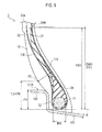
Fig. 2 is a schematic diagram illustrating thebead portion 12 to asidewall portion 13 of thepneumatic tire 1.Fig. 3 is a magnified view of the region A inFig. 2 , that is, a magnified sectional view of a stiffener and a carcass in the radial direction and the tread width direction of the pneumatic tire of the first embodiment. - A
carcass 20 comprises aply 25 composed of a plurality ofcarcass cords 23 coated with arubber material 24 toroidally extending between a pair ofbead cores 11. A part of thestiffener 31 and thepad rubber 32 contacts at least therubber material 24 that constitute thecarcass body 21. Thecarcass 20 has a parallel region Sp, where the distance G between the centers of the cords of thecarcass body 21 and the carcass folded-back portion 22 on a line H normal to thecarcass body 21 becomes substantially constant. The substantially constant distance G means that when a minimum value of the distance G is assumed to be Gs, the following relation is at least satisfied: Gs≦G≦ 1.2Gs
Theend 31A of thestiffener 31 outside in the tire radial direction is located in the parallel region Sp. - In the embodiment, when defining a line H1 normal to the
carcass body 21 passing through a point P2 equivalent to 1.2FH in thebead portion 12 from a rim base line toward outside in the tire radial direction, the distance G1 between thecarcass body 21 and the carcass folded-back portion 22 on the normal line H1 and the length BW of thebead core 11 in the tire width direction satisfy the relation of 0.3BW≦ G1≦0.4BW - Further, in the embodiment, the distances G and G1 between the
carcass body 21 and the carcass folded-back portion 22 are the distances between the centers of thecarcass cords 23 that constitute thecarcass body 21 and the carcass folded-back portion 22. -
Fig. 4 is a schematic diagram explaining aspects of thesidewall portion 13 of thepneumatic tire 1 being deformed. When simulating aspects of thesidewall portion 13 of thepneumatic tire 1 being deformed by using a finite element analysis method, the following deformation can be simulated. When a heavy load is applied to thepneumatic tire 1, bending deformation occurs in thesidewall portion 13 at a base point of a part where thebead portion 12 contacts therim flange 101. InFig. 4 , a chain line indicates thesidewall portion 13 before being deformed, and a solid line indicates thewall portion 13 after being deformed. When thesidewall portion 13 falls outside in the tire width direction, a force indicated by the arrow direction is applied to the part where thebead portion 12 continues to thesidewall portion 13. - At this time, the
carcass body 21 becomes a neutral axis and deforms a little, and thestiffener 31 andpad rubber 32 arranged between thecarcass body 21 and carcass folded-back portion 22 are pressed and deformed as being compressed between thecarcass body 21 and the carcass folded-back portion 22. -
Fig. 5 is a magnified view showing the states of thecarcass 20 andstiffener 31 in thedeformed sidewall portion 13. When thesidewall portion 13 falls outside in the tire width direction at a base point (a neutral axis) of the part where thebead portion 12 contacts therim flange 101, inside thesidewall portion 13, therubber material 24 located between thestiffener 31 andcarcass cord 23 suffers distortion of pulling toward in the outside in tire radial direction along the carcass body 21 (indicated by the black arrow f1 inFig. 5 ). Therubber material 24 located more inside in the tire width direction than thecarcass cord 23 suffers distortion of pulling inside in the tire radial direction along the carcass body 21 (indicated by the black arrow f2 inFig. 5 ). - The
stiffener 31 is pressed and compressed between thecarcass body 21 and the carcass folded-back portion 22, and is expanded outside in the tire radial direction along thecarcass body 21. As a result, therubber material 24 is pulled outside in the tire radial direction along the carcass body, and the distortion indicated by the black arrow f1 direction is increased. - According to the analysis of deformation by a finite element method, the applicants minutely studied the relationship between the
stiffener 31 andcarcass 20, which can prevent shear distortion in therubber material 24 close to thestiffener 31 of thecarcass body 21 without loosing the essential function of thestiffener 31 to prevent falling of thesidewall portion 13. -
Fig. 6 is a graph showing the results of analysis of deformation based on a finite element method. An index that represents the distortion is calculated by changing the value of (KSH-FH)/(OWH-FH) to 0.15 to 0.35. As a result of the analysis, it is proved that an index of distortion applied to therubber material 24 due to deformation of thesidewall portion 13 can be decreased when the height KSH from the rim base line BL to theend 31A outside in the tire radial direction of thestiffener 31, the height OWH from the rim base line BL to the carcassmaximum width portion 20W, and the height FH from the rim base line BL to theend 101A of therim flange 101 outside in the tire radial direction satisfy the relation of 0.2≦ [(KSH-FH)/(OWH-FH)]≦ 0.28.
As the distortion applied to therubber material 24 due to deformation of thesidewall portion 13 can be decreased, it is possible to prevent peel-off of therubber material 24 from thestiffener 31 due to deformation of thesidewall portion 13, peel-off of therubber material 24 from thecarcass cord 23, and to prevent deterioration in the durability of the part ranging from thebead portion 12 to thesidewall portion 13. - Further, in the embodiment, when the 100% elongation modulus Mn1 of the
stiffener 31, the 100% elongation modulus Mn2 of thepad rubber 32, and the 100% elongation modulus Mn3 of therubber material 24, respectively, satisfy the relation of Mn1>Mn3>Mn2.
Even if deformation occurs in therubber material 24 contacting thestiffener 31 due to deformation of thesidewall portion 13, is easy to follow the deformation, and therubber material 24 can be prevented from being damaged by a shear stress. It is thus possible to ensure the rigidity and to improve the durability of the part ranging from thebead portion 12 to thesidewall portion 13 at a high level in a pneumatic tire. - In the
pneumatic tire 1, theend 22a of the carcass folded-back portion 22 is arranged at a position at the height CE from the rim base line BL, and the height CE and the height SH from the rim base line BL to the carcass on the equator line CL of the tire satisfy the relation of 0.4SH≦CE≦0.6SH. By arranging theend 22a of the carcass folded-back portion 22 to satisfy this relationship, it is possible to prevent cracks in a surrounding rubber due to theend 22a of the carcass folded-back portion 22. - Further, in the
pneumatic tire 1, when defining a line H normal to thecarcass body 21 passing through a point equivalent to 1.2FH in thebead portion 12 from the rim base line BL toward outside in the tire radial direction, the distance G between thecarcass body 21 and the carcass folded-back portion 22 on the normal line H and the length BW of thebead core 11 in the tire width direction satisfy the relation of 0.3BW≦G≦0.4BW. - At the point P2 equivalent to 1.2FH from the rim base line BL to outside in the tire radial direction, bending deformations of the
carcass body 21 and the carcass folded-back portion 22 become maximized. By setting the distance G between thecarcass body 21 and the carcass folded-back portion 22 close to the above-mentioned range in this part, a compression strain produced in the carcass folded-back portion 22 can be decreased. - A second embodiment will be explained with reference to the drawings. Particularly, explanations will be given of (2-1) configuration of a part ranging from a bead portion to a sidewall portion, and (2-2) Functions and effects.
Fig. 7 shows a magnified sectional view in tire radial direction and tire width direction illustrating a part ranging from a bead portion to a sidewall portion of a pneumatic tire according to a second embodiment. In the second embodiment, the same reference signs are given to the same parts as t hose in the first embodiment, and detailed description thereof is omitted. - In a
pneumatic tire 2 shown as a second embodiment, the space between thecarcass body 21 and the carcass folded-back portion 22 varies outside in the tire radial direction. In thepneumatic tire 2 of the second embodiment, astiffener 131 and apad rubber 132 are provided between acarcass body 21 and a carcass folded-back portion 22. - In the
pneumatic tire 2 shown as a second embodiment, the height KSH from a rim base line BL to anend 131A of thestiffener 131 outside in the tire radial direction, the height OWH from the rim base line BL to the carcassmaximum width portion 20W, and the height FH from the rim base line BL to anend 101A of arim flange 101 outside in the tire radial direction satisfy the relation of 0.2 ≦ [(KSH-FH)/(OWH-FH)]≦0.28. - Further, the 100% elongation modulus Mn1 of the
stiffener 131, the 100% elongation modulus Mn2 of thepad rubber 132, and the 100% elongation modulus Mn3 of therubber material 24, respectively, satisfy the relation of Mn1>Mn3>Mn2. - Further, a
carcass 20 has a gradual decrease region Sd, where the distance G0 between thecarcass body 21 and the carcass folded-back portion 22 on the line OH normal to thecarcass body 21 gradually decreases toward outside in the tire radial direction, and theend 131A of thestiffener 131 outside in the tire radial direction is located in the gradual decrease region Sd. - Further, in the second embodiment, the
carcass 20 has ashortest part 201, where the distance G from thecarcass body 21 to the carcass folded-back portion 22 becomes minimum in the gradual decrease region Sd, in a part outside the gradual decrease region Sd outside in the tire radial direction. The distance from thecarcass body 21 to the carcass folded-back portion 22 in the shortest portion is expressed as Gmin. - In a part outside the
shortest part 201 outside in the tire radial direction, there is provided alongest part 202 where the distance G from thecarcass body 21 to the carcass folded-back portion 22 becomes maximum. The distance from thecarcass body 21 to the carcass folded-back portion 22 in thelongest part 202 is expressed as Gmax. - In the
embodiment 2, there is an outer gradual decrease region Sdo where the distance from thecarcass body 21 to the carcass folded-back portion 22 gradually decreases from thelongest part 202 toward outside in the tire radial direction. When defining a line H2 normal to thecarcass body 21 passing through thelongest part 202 and a point P3 intersecting the surface of thesidewall portion 13, the height HP3 from the rim base line BL to the intersection point P3 satisfies the relation of HP3≦3.75FH. - In the embodiment, the distances Gmin, Gmax, and G0 between the
carcass body 21 and the carcass folded-back portion 22 are the distances between the centers of thecarcass cords 23 that constitute thecarcass body 21 and the carcass folded-back portion 22. - In the
pneumatic tire 2, ashortest part 201, where the distance G from thecarcass body 21 to the carcass folded-back portion 22 becomes minimum in the gradual decrease region Sd, is provided in a part outside the gradual decrease region Sd outside in the tire radial direction. In the gradual decrease region Sd where the distances between the cords forming thecarcass body 21 and carcass folded-back portion 22 gradually decreases, deformation due to compression occurred in the carcass folded-back portion 22 is decreased. - As the
longest part 202 is provided by gradually increasing the distance between thecarcass body 21 and the carcass folded-back portion 22 from theshortest part 201 outside in the tire radial direction, the carcass folded-back portion 22 separates from a position (a neutral axis) that is a base point of bending the carcass folded-back portion 22, the carcass folded-back portion 22 is pulled outside in the tire radial direction, and deformation due to compression occurred in the carcass folded-back portion 22 is decreased. - Therefore, it is possible to prevent peel-off of the
rubber material 24 from thestiffener 131 due to deformation of thesidewall portion 13, peel-off of therubber material 24 from thecarcass cord 23, and deterioration in the durability of the part ranging from thebead portion 12 to thesidewall portion 13. It is thus possible to ensure at a high level, the rigidity and to improve the durability of the part ranging from thebead portion 12 to thesidewall portion 13 in the pneumatic tire. By setting thelongest part 202 between to 3.75FH from the rim base line BL, it is possible to increase the ratio of the pad rubber and to prevent a large shear distortion in therubber material 24. - A third embodiment will be explained with reference to the drawings. Particularly, explanations will be given of (3-1) Configuration of a part ranging from a bead portion to a sidewall portion, and (3-2) Functions and effects.
Fig. 8 shows a magnified sectional view in tire radial direction and tire width direction illustrating a part ranging from a bead portion to a sidewall portion of a pneumatic tire according to a third embodiment. In the third embodiment, the same reference signs are given to the same parts as those in the first and second embodiments, and detailed description thereof is omitted. - In a
pneumatic tire 3 shown as a third embodiment, astiffener 133 and apad rubber 134 are provided between acarcass body 21 and a carcass folded-back portion 22. - In the
pneumatic tire 3 shown as a third embodiment, the height KSH from a rim base line BL to anend 133A of thestiffener 133 outside in the tire radial direction, the height OWH from the rim base line BL to the carcassmaximum width portion 20W, and the height FH from the rim base line BL to anend 101A of arim flange 101 outside in the tire radial direction satisfy the relation of 0.2≦ [(KSH-FH)/(OWH-FH)]≦0.28. - Further, the 100% elongation modulus Mn1 of the
stiffener 133, the 100% elongation modulus Mn2 of thepad rubber 134, and the 100% elongation modulus Mn3 of therubber material 24, respectively, satisfy the relation of Mn1>Mn3>Mn2. - On a line H4 normal to the
carcass body 21 passing through theend 133A of thestiffener 133 outside in the tire radial direction, when the distance between the centers of the cords of thecarcass body 21 and carcass folded-back portion 22 is defined as DA, and the distance between thecarcass body 21 and the carcass folded-back portion 22 on the normal line H4 as G3, theend 133A of thestiffener 133 is within a range of 0.25G3 to 0.75G3. - In the
pneumatic tire 3, thecarcass body 21 does not directly contact theend 133A of thestiffener 133, and it is possible to decrease distortion of therubber material 24 of thecarcass body 21 due to theend 133A of thestiffener 133. Therefore, it is possible to prevent peel-off of therubber material 24 from thestiffener 133 due to deformation of thesidewall portion 13, peel-off of therubber material 24 from thecarcass cord 23, and reduction in the durability of the part from thebead portion 12 to thesidewall portion 13. When the distance G3 between thecarcass body 21 and the carcass folded-back portion 22 on the normal line H4 of thecarcass body 21 does not satisfy the relation of 0.25G3≦DA≦0.75G3, the thickness of thepad rubber 134 decreases, distortion concentrates on thepad rubber 134, and the rubber material becomes easy to peel off from thepad rubber 134. This is unsuitable. - A fourth embodiment will be explained with reference to the drawings. Particularly, explanations will be given of (4-1) configuration of a part ranging from a bead portion to a sidewall portion, and (4-2) Functions and effects.
Fig. 9 shows a magnified sectional view in direction of the tire and width directions of the tire illustrating a part ranging from a bead portion to a sidewall portion of a pneumatic tire according to the fourth embodiment. In the fourth embodiment, the same reference signs are given to the same parts as those in the first to third embodiments, and detailed description thereof is omitted. - In a
pneumatic tire 4 shown as the fourth embodiment, astiffener 135 and apad rubber 136 are provided between acarcass body 21 and a carcass folded-back portion 22. - In the
pneumatic tire 4 shown as the fourth embodiment, the height KSH from a rim base line BL to an end 135A of thestiffener 135 outside in the tire radial direction, the height OWH from the rim base line BL to the carcassmaximum width portion 20W, and the height FH from the rim base line BL to anend 101A of arim flange 101 outside in the tire radial direction satisfy the relation of 0.2≦ [(KSH-FH)/(OWH-FH)]≦0.28. - Further, the 100% elongation modulus Mn1 of the
stiffener 135, the 100% elongation modulus Mn2 of thepad rubber 136, and the 100% elongation modulus Mn3 of therubber material 24, respectively, satisfy the relation of Mn1>Mn3>Mn2. - Further, a
buffer rubber 140 is provided between the end 135A of thestiffener 135 outside in the tire radial direction and thecarcass body 21, and between the end 136A of thepad rubber 136 inside in the tire radial direction and thecarcass body 21. The 100% elongation modulus Mn4 of thebuffer rubber 140 is 0.7 to 1.0 times of the 100% elongation modulus of thepad rubber 136, that is, satisfying the relation of 0.7×Mn2≦Mn4≦Mn2. - In the
pneumatic tire 4, as thebuffer rubber 140 is provided in a part likely to receive a reactive force from a rim flange, the rigidity difference between thecarcass body 21 andstiffener 135 can be decreased, and distortion of therubber material 24 can be decreased. When the 100% elongation modulus of the buffer rubber decreases to lower than 70% of the 100% elongation modulus of thepad rubber 136, distortion concentrates on the buffer rubber, and the buffer rubber is likely suffer damage. This is unsuitable. - Although the present invention has been described in terms of preferred embodiments, the foregoing discussion and drawings are not to be understood as restrictive of the invention. It will be appreciated that various alternative embodiments, examples might be made by those skilled in the art. For example, the embodiments of the present invention may be modified as follows.
- In the embodiments, the 100% elongation modulus Mn1 of the
stiffener 31, the 100% elongation modulus Mn2 of thepad rubber 32, and the 100% elongation modulus Mn3 of therubber material 24, respectively, satisfy the relation of Mn1>Mn3>Mn2, but this is not restrictive. For example, it may satisfy the relation of Mn1>Mn2> Mn3. - In the embodiments, the height PSH from the rim base line BL to the
end 32B of thepad rubber 32 outside in the tire radial direction has been defined substantially equal to the height OWH from the rim base line BL to the carcassmaximum width portion 20W. However, for example, the heights may be PSH<OWH. The end of the pad rubber outside in the tire radial direction may be closer to inside in the tire radial direction than the height CE. In this case, a hard-to-crack rubber may be provided adjacent to theend 22a of the carcass folded-back portion 22. As a result, it is possible to prevent a crack in the surrounding rubber caused by theend 22a of the carcass folded-back portion 22. As a hard-to-crack rubber, it is permitted to use a rubber with the 100% elongation modules lower than the 100% elongation modules of thepad rubber 32. - As described above, many embodiments not disclosed herein are to be understood as included in the present invention. The scope of the invention should, therefore, be defined by the appended claims.
- We have manufactured pneumatic tires of examples 1 - 4 and comparative examples 1-4 by changing conditions, and conducted durability tests to examine the durability of a part from a bead portion to a sidewall portion under the following conditions. The example 1 is a
pneumatic tire 1 having the structure shown inFig. 2 , the example 2 is apneumatic tire 2 having the structure shown inFig. 7 , the example 3 is apneumatic tire 3 having the structure shown inFig. 8 , and the example 4 is apneumatic tire 4 having the structure shown inFig. 9 , respectively. - The structure of the comparative example 1 is shown in
Fig. 10 . The structure of the comparative example 2 is shown inFig. 11 . The structures of the comparative examples 1 and 2 are similar to those shown inFigs. 2 and7 , except that the end of the stiffener outside in the tire radial direction is more outside in the tire radial direction than thepneumatic tires Figs. 2 and7 . In the comparative example 3, the ratio of the distance DA to the distance G3 in thepneumatic tire 3 shown inFig. 8 is changed.
Tire size: 59/80R63
Inside pressure: Set to 500kPa.
Rim: TRA standard rim
Drum tester: Drum diameter 7m
Drum rotation speed: 8km/h
Drum load: 150 % to 180% of standard load 999.6kN (Step load system) A step load system sets a standard load of 150% at a startup when applying a drum load to an object pneumatic tire for 12 hours, thereafter, add 10% of the standard load, and finally applies 180% of the standard load. - After 12 hours, we have cut out a part ranging from a bead portion to a sidewall portion of the pneumatic tire, and visually checked the cord and rubber material for cracks. The durability test results are shown in
Fig. 12 . The test results are expressed by indexes assuming a comparative example to be 100. - According to the results shown in
Fig. 12 , the pneumatic tire of the examples 1 to 4, it is proved that the cord of the carcass folded-back portion is not cracked, the distortion index of therubber material 24 is decreased, and the rubber material contacting the stiffener is not - According to the above results, it is proved that in the pneumatic tire of the example, the rigidity of the part ranging from the bead portion to sidewall portion is ensured, and the durability of that part can be enhanced at a high level.
- It should be noted by reference the entire contents of Japanese Patent Application No.
2010-207946 (filed September 16, 2010 - As described above, according to the pneumatic tire of the present invention, it is possible to ensure the rigidity and enhance the durability of a part ranging from a bead portion to sidewall portion at a high level.
Claims (8)
- A pneumatic tire comprising a carcass having a carcass body composed of a ply formed of a plurality of carcass cords, covered with rubber material, toroidally extending between a pair of bead cores, and a carcass folded-back portion where the carcass body wound around the bead core from inside toward outside of the tire and extended outside in a tire radial direction, wherein
a gradual decrease region is provided, in which a distance between the carcass body and the carcass folded-back portion along a line normal to the carcass body gradually decreases toward outside in the tire radial direction,
a first filling material and a second filling material sequentially arranged from the bead core toward outside in the tire radial direction, are provided between the carcass body and the carcass folded-back portion located outside in a tire width direction than the carcass body located,
an end of the first filling material outside in the tire radial direction is located in the gradual decrease region,
a part of the first filling material and the second filling material contacts with the rubber material forming the carcass body,
the end of the first filling material outside in the tire radial direction and an end of the second filling material inside in the tire radial direction are overlapped in the tire width direction,
a thickness in the tire width direction of the first filling material at the end outside in the tire radial direction decreases toward outside in the tire radial direction,
an end of the second filling material inside in the tire radial direction is located more inside in the tire radial direction than a contact position in contact with a rim flange of a rim defined by standards for mounting the pneumatic tire in the bead portion of the pneumatic tire,
a height CE from a rim base line, which is an axis line of the tire passing through a position in the rim defining a rim diameter, to an end of the carcass folded-back portion, and a height OWH from the rim base line to a carcass maximum width portion of the carcass body having a maximum width in the tire width direction, satisfy a relation of 0.85OWH≦CE≦1.2OWH, and
a height KSH from the rim base line to the end of the first filling material outside in the tire radial direction, the height OWH, and a height FH from the rim base line to the end of the rim flange outside in the tire radial direction, satisfy a relation of 0.2≦ [(KSH-FH)/(OWH-FH)]≦ 0.28. - The pneumatic tire according to claim 1, wherein
a 100% elongation modulus Mn1 of the first filling material, a 100% elongation modulus Mn2 of the second filling material, and a 100% elongation modulus Mn3 of the rubber material satisfy a relation of Mn1>Mn3>Mn2. - The pneumatic tire according to claim 1, wherein
the carcass has a parallel region where a distance between the carcass body and the carcass folded-back portion on the line normal to the carcass body is constant, and
the end of the first filling material outside in the tire radial direction is located in the parallel region. - The pneumatic tire according to claim 1, wherein
the carcass has
a longest part, where the distance between the carcass body and the carcass folded-back portion is maximum, more outside in the tire radial direction than the gradual decrease region, and
an outer gradual decrease region, where the distance between the carcass body and the carcass folded-back portion gradually decreases from the longest part toward outside in the tire radial direction, and
the longest part is located within a height of 3.75FH from the rim base line outside in the tire radial direction. - The pneumatic tire according to claim 1, wherein
a distance DA between the carcass body and the end of the first filling material outside in the tire radial direction on the line normal to the carcass body passing through the end of the first filling material outside in the tire radial direction, and a distance G between the carcass body and the carcass folded-back portion on the line normal to the carcass body, satisfy a relation of 0.25G≦DA≦0.75G. - The pneumatic tire according to claim 2, wherein
a third filling material located between the end of the first filling material outside in the tire radial direction and the carcass body, is provided between the end of the second filling material inside in the tire radial direction and the carcass body, and
the 100% elongation modulus of the third filling material is 0.7 to 1.0 times of the 100% elongation modulus of the second filling material. - The pneumatic tire according to claim 1, wherein
the height CE and the height SH from the rim base line to the carcass on an equator line of the pneumatic tire satisfy a relation of 0.4SH≦CE≦0.6SH. - The pneumatic tire according to claim 1, wherein
a distance G1 between the carcass body and the carcass folded-back portion on a line normal to the carcass body passing through a position in the bead portion equivalent to 1.2FH from the rim base line toward outside in the tire radial direction, and a length BW of the bead core in the tire width direction satisfy a relation of 0.3BW≦G1≦0.4BW.
Applications Claiming Priority (2)
| Application Number | Priority Date | Filing Date | Title |
|---|---|---|---|
| JP2010207946 | 2010-09-16 | ||
| PCT/JP2011/071284 WO2012036292A1 (en) | 2010-09-16 | 2011-09-16 | Pneumatic tire |
Publications (3)
| Publication Number | Publication Date |
|---|---|
| EP2617585A1 true EP2617585A1 (en) | 2013-07-24 |
| EP2617585A4 EP2617585A4 (en) | 2015-10-28 |
| EP2617585B1 EP2617585B1 (en) | 2016-12-21 |
Family
ID=45831744
Family Applications (1)
| Application Number | Title | Priority Date | Filing Date |
|---|---|---|---|
| EP11825290.7A Not-in-force EP2617585B1 (en) | 2010-09-16 | 2011-09-16 | Pneumatic tire |
Country Status (7)
| Country | Link |
|---|---|
| US (1) | US9272584B2 (en) |
| EP (1) | EP2617585B1 (en) |
| JP (1) | JP5671546B2 (en) |
| CN (1) | CN103108759B (en) |
| BR (1) | BR112013006017B1 (en) |
| ES (1) | ES2618928T3 (en) |
| WO (1) | WO2012036292A1 (en) |
Cited By (1)
| Publication number | Priority date | Publication date | Assignee | Title |
|---|---|---|---|---|
| EP2641755A4 (en) * | 2011-03-07 | 2014-12-03 | Bridgestone Corp | Pneumatic tire |
Families Citing this family (10)
| Publication number | Priority date | Publication date | Assignee | Title |
|---|---|---|---|---|
| FR2992898B1 (en) * | 2012-07-04 | 2015-10-30 | Michelin & Cie | PNEUMATIC BOURRELET FOR HEAVY VEHICLE TYPE GENIE CIVIL |
| FR2999474B1 (en) * | 2012-12-13 | 2016-03-11 | Michelin & Cie | PNEUMATIC BOURRELET FOR HEAVY VEHICLE TYPE GENIE CIVIL |
| JP6318480B2 (en) | 2013-06-21 | 2018-05-09 | 横浜ゴム株式会社 | Pneumatic tire |
| US10994578B2 (en) * | 2015-09-14 | 2021-05-04 | Jiangsu University | Method for improving production process for wide-base truck radial tire |
| JP6785104B2 (en) * | 2015-10-02 | 2020-11-18 | 株式会社ブリヂストン | Tires for construction vehicles |
| US11046124B2 (en) * | 2016-08-30 | 2021-06-29 | Bridgestone Americas Tire Operations, Llc | Pneumatic tire |
| JP6939560B2 (en) * | 2016-10-06 | 2021-09-22 | 横浜ゴム株式会社 | Bias tire |
| JP7139776B2 (en) * | 2018-08-20 | 2022-09-21 | 住友ゴム工業株式会社 | pneumatic tire |
| JP7283301B2 (en) * | 2019-08-07 | 2023-05-30 | 横浜ゴム株式会社 | Heavy duty pneumatic tire |
| IT202100009365A1 (en) * | 2021-04-14 | 2022-10-14 | Bridgestone Europe Nv Sa | TIRE PROVIDED WITH A TEMPORARY IDENTIFICATION LABEL |
Family Cites Families (29)
| Publication number | Priority date | Publication date | Assignee | Title |
|---|---|---|---|---|
| FR2075851A1 (en) * | 1969-12-23 | 1971-10-15 | Michelin & Cie | |
| JPS5216704A (en) * | 1975-07-30 | 1977-02-08 | Bridgestone Corp | Heavy load radial tire |
| JPS61275010A (en) | 1985-05-29 | 1986-12-05 | Sumitomo Rubber Ind Ltd | Pneumatic radial tire for heavy-load use |
| JP2886566B2 (en) * | 1989-09-01 | 1999-04-26 | 株式会社ブリヂストン | Pneumatic radial tires for construction vehicles running on rough terrain |
| JPH04185510A (en) * | 1990-11-20 | 1992-07-02 | Bridgestone Corp | Pneumatic radial tire for construction vehicle |
| JPH05124408A (en) * | 1991-11-08 | 1993-05-21 | Yokohama Rubber Co Ltd:The | Pneumatic radial tire |
| JP3062324B2 (en) * | 1991-11-20 | 2000-07-10 | オーツタイヤ株式会社 | Pneumatic radial tire |
| JPH09272313A (en) | 1996-04-09 | 1997-10-21 | Bridgestone Corp | Pneumatic radial tire |
| JP3332330B2 (en) | 1997-06-27 | 2002-10-07 | 住友ゴム工業株式会社 | Pneumatic tire and manufacturing method thereof |
| US6273162B1 (en) * | 1998-04-10 | 2001-08-14 | Sumitomo Rubber Industries, Ltd. | Pneumatic tire with specified bead portion |
| JPH11301218A (en) * | 1998-04-15 | 1999-11-02 | Yokohama Rubber Co Ltd:The | Automotive pneumatic tire |
| DE69910523T2 (en) | 1998-10-29 | 2004-03-18 | Sumitomo Rubber Industries Ltd., Kobe | tires |
| JP3464181B2 (en) * | 1998-10-29 | 2003-11-05 | 住友ゴム工業株式会社 | Pneumatic tire |
| JP3325004B2 (en) * | 1999-10-21 | 2002-09-17 | 住友ゴム工業株式会社 | Pneumatic tire |
| JP2001150910A (en) * | 1999-11-29 | 2001-06-05 | Bridgestone Corp | Pneumatic tire |
| AU2001246424A1 (en) * | 2000-02-21 | 2001-08-27 | Pirelli Pneumatici S.P.A. | Motor vehicle tyre with an antiabrasive band capable of reducing its rolling resistance |
| JP4643817B2 (en) * | 2000-11-27 | 2011-03-02 | 住友ゴム工業株式会社 | Pneumatic tire |
| JP4496677B2 (en) | 2001-06-28 | 2010-07-07 | 横浜ゴム株式会社 | Pneumatic radial tire for construction vehicles |
| JP4263934B2 (en) * | 2003-04-04 | 2009-05-13 | 住友ゴム工業株式会社 | Pneumatic tire |
| DE102005041937A1 (en) * | 2005-09-03 | 2007-03-08 | Continental Aktiengesellschaft | Pneumatic vehicle tires and method of manufacture |
| JP4741955B2 (en) * | 2006-02-13 | 2011-08-10 | 株式会社ブリヂストン | Pneumatic tire |
| JP2007223516A (en) * | 2006-02-24 | 2007-09-06 | Sumitomo Rubber Ind Ltd | Pneumatic tire |
| JP4681497B2 (en) * | 2006-05-08 | 2011-05-11 | 住友ゴム工業株式会社 | Pneumatic tire |
| JP2007301830A (en) * | 2006-05-11 | 2007-11-22 | Bridgestone Corp | Method for producing pneumatic radial tire for heavy load and pneumatic radial tire for heavy load |
| JP5216304B2 (en) * | 2007-11-08 | 2013-06-19 | 株式会社ブリヂストン | Pneumatic tires for construction vehicles |
| JP2010006322A (en) * | 2008-06-30 | 2010-01-14 | Yokohama Rubber Co Ltd:The | Pneumatic tire |
| JP5277881B2 (en) * | 2008-11-10 | 2013-08-28 | 横浜ゴム株式会社 | Pneumatic tire |
| JP5722085B2 (en) * | 2011-03-07 | 2015-05-20 | 株式会社ブリヂストン | Pneumatic tire |
| FR2976222B1 (en) * | 2011-06-07 | 2016-07-01 | Soc De Tech Michelin | PNEUMATIC BOURRELET FOR HEAVY VEHICLE TYPE GENIE CIVIL |
-
2011
- 2011-09-16 CN CN201180044677.XA patent/CN103108759B/en not_active Expired - Fee Related
- 2011-09-16 JP JP2012534075A patent/JP5671546B2/en not_active Expired - Fee Related
- 2011-09-16 WO PCT/JP2011/071284 patent/WO2012036292A1/en not_active Ceased
- 2011-09-16 ES ES11825290.7T patent/ES2618928T3/en active Active
- 2011-09-16 US US13/824,326 patent/US9272584B2/en active Active
- 2011-09-16 BR BR112013006017-4A patent/BR112013006017B1/en not_active IP Right Cessation
- 2011-09-16 EP EP11825290.7A patent/EP2617585B1/en not_active Not-in-force
Cited By (1)
| Publication number | Priority date | Publication date | Assignee | Title |
|---|---|---|---|---|
| EP2641755A4 (en) * | 2011-03-07 | 2014-12-03 | Bridgestone Corp | Pneumatic tire |
Also Published As
| Publication number | Publication date |
|---|---|
| BR112013006017B1 (en) | 2021-11-30 |
| US9272584B2 (en) | 2016-03-01 |
| EP2617585B1 (en) | 2016-12-21 |
| ES2618928T3 (en) | 2017-06-22 |
| CN103108759A (en) | 2013-05-15 |
| CN103108759B (en) | 2015-04-08 |
| EP2617585A4 (en) | 2015-10-28 |
| US20130174956A1 (en) | 2013-07-11 |
| JP5671546B2 (en) | 2015-02-18 |
| WO2012036292A1 (en) | 2012-03-22 |
| BR112013006017A2 (en) | 2016-06-07 |
| JPWO2012036292A1 (en) | 2014-02-03 |
Similar Documents
| Publication | Publication Date | Title |
|---|---|---|
| EP2617585B1 (en) | Pneumatic tire | |
| EP3127717A1 (en) | Pneumatic tire | |
| AU2015212144B2 (en) | Run-flat radial tyre | |
| EP2708381A1 (en) | Pneumatic tire | |
| JP4801527B2 (en) | Heavy duty tire | |
| JP2009113715A (en) | Pneumatic tire | |
| JP6377390B2 (en) | Run-flat radial tire | |
| US6386259B1 (en) | Heavy duty radial tire with specified arrangement of chafer and carcass turnup | |
| US9126458B2 (en) | Pneumatic tire | |
| EP3103660A9 (en) | Run-flat radial tire | |
| EP3299186B1 (en) | Pneumatic radial tire for heavy loads | |
| JP5497805B2 (en) | Heavy duty pneumatic tire | |
| WO2018159035A1 (en) | Pneumatic tire | |
| EP2641752A1 (en) | Pneumatic tire | |
| JP7494497B2 (en) | Pneumatic tires | |
| EP1262337A2 (en) | Pneumatic tire | |
| JP4763187B2 (en) | Pneumatic tire | |
| EP3281808A1 (en) | A tire having chafer structure for enhancing bead endurance | |
| JP2007230515A (en) | Heavy duty tire | |
| JP2006312413A (en) | Heavy duty tire | |
| EP1985469A1 (en) | Pneumatic tire | |
| JP2000198332A (en) | Heavy duty pneumatic tires | |
| JP4945136B2 (en) | Pneumatic tire | |
| EP4711155A1 (en) | Heavy duty tire | |
| EP3473453A1 (en) | Pneumatic tire for heavy loads |
Legal Events
| Date | Code | Title | Description |
|---|---|---|---|
| PUAI | Public reference made under article 153(3) epc to a published international application that has entered the european phase |
Free format text: ORIGINAL CODE: 0009012 |
|
| 17P | Request for examination filed |
Effective date: 20130327 |
|
| AK | Designated contracting states |
Kind code of ref document: A1 Designated state(s): AL AT BE BG CH CY CZ DE DK EE ES FI FR GB GR HR HU IE IS IT LI LT LU LV MC MK MT NL NO PL PT RO RS SE SI SK SM TR |
|
| DAX | Request for extension of the european patent (deleted) | ||
| RA4 | Supplementary search report drawn up and despatched (corrected) |
Effective date: 20150925 |
|
| RIC1 | Information provided on ipc code assigned before grant |
Ipc: B60C 15/06 20060101AFI20150921BHEP Ipc: B60C 15/00 20060101ALI20150921BHEP Ipc: B60C 9/02 20060101ALI20150921BHEP |
|
| GRAP | Despatch of communication of intention to grant a patent |
Free format text: ORIGINAL CODE: EPIDOSNIGR1 |
|
| RIC1 | Information provided on ipc code assigned before grant |
Ipc: B60C 9/02 20060101ALI20160609BHEP Ipc: B60C 15/00 20060101ALI20160609BHEP Ipc: B60C 15/06 20060101AFI20160609BHEP |
|
| INTG | Intention to grant announced |
Effective date: 20160706 |
|
| GRAS | Grant fee paid |
Free format text: ORIGINAL CODE: EPIDOSNIGR3 |
|
| GRAA | (expected) grant |
Free format text: ORIGINAL CODE: 0009210 |
|
| AK | Designated contracting states |
Kind code of ref document: B1 Designated state(s): AL AT BE BG CH CY CZ DE DK EE ES FI FR GB GR HR HU IE IS IT LI LT LU LV MC MK MT NL NO PL PT RO RS SE SI SK SM TR |
|
| REG | Reference to a national code |
Ref country code: GB Ref legal event code: FG4D |
|
| REG | Reference to a national code |
Ref country code: CH Ref legal event code: EP |
|
| REG | Reference to a national code |
Ref country code: IE Ref legal event code: FG4D |
|
| REG | Reference to a national code |
Ref country code: AT Ref legal event code: REF Ref document number: 855142 Country of ref document: AT Kind code of ref document: T Effective date: 20170115 |
|
| REG | Reference to a national code |
Ref country code: DE Ref legal event code: R096 Ref document number: 602011033706 Country of ref document: DE |
|
| PG25 | Lapsed in a contracting state [announced via postgrant information from national office to epo] |
Ref country code: LV Free format text: LAPSE BECAUSE OF FAILURE TO SUBMIT A TRANSLATION OF THE DESCRIPTION OR TO PAY THE FEE WITHIN THE PRESCRIBED TIME-LIMIT Effective date: 20161221 |
|
| REG | Reference to a national code |
Ref country code: LT Ref legal event code: MG4D |
|
| REG | Reference to a national code |
Ref country code: NL Ref legal event code: MP Effective date: 20161221 |
|
| PG25 | Lapsed in a contracting state [announced via postgrant information from national office to epo] |
Ref country code: LT Free format text: LAPSE BECAUSE OF FAILURE TO SUBMIT A TRANSLATION OF THE DESCRIPTION OR TO PAY THE FEE WITHIN THE PRESCRIBED TIME-LIMIT Effective date: 20161221 Ref country code: NO Free format text: LAPSE BECAUSE OF FAILURE TO SUBMIT A TRANSLATION OF THE DESCRIPTION OR TO PAY THE FEE WITHIN THE PRESCRIBED TIME-LIMIT Effective date: 20170321 Ref country code: GR Free format text: LAPSE BECAUSE OF FAILURE TO SUBMIT A TRANSLATION OF THE DESCRIPTION OR TO PAY THE FEE WITHIN THE PRESCRIBED TIME-LIMIT Effective date: 20170322 Ref country code: SE Free format text: LAPSE BECAUSE OF FAILURE TO SUBMIT A TRANSLATION OF THE DESCRIPTION OR TO PAY THE FEE WITHIN THE PRESCRIBED TIME-LIMIT Effective date: 20161221 |
|
| REG | Reference to a national code |
Ref country code: AT Ref legal event code: MK05 Ref document number: 855142 Country of ref document: AT Kind code of ref document: T Effective date: 20161221 |
|
| PG25 | Lapsed in a contracting state [announced via postgrant information from national office to epo] |
Ref country code: RS Free format text: LAPSE BECAUSE OF FAILURE TO SUBMIT A TRANSLATION OF THE DESCRIPTION OR TO PAY THE FEE WITHIN THE PRESCRIBED TIME-LIMIT Effective date: 20161221 Ref country code: FI Free format text: LAPSE BECAUSE OF FAILURE TO SUBMIT A TRANSLATION OF THE DESCRIPTION OR TO PAY THE FEE WITHIN THE PRESCRIBED TIME-LIMIT Effective date: 20161221 Ref country code: HR Free format text: LAPSE BECAUSE OF FAILURE TO SUBMIT A TRANSLATION OF THE DESCRIPTION OR TO PAY THE FEE WITHIN THE PRESCRIBED TIME-LIMIT Effective date: 20161221 |
|
| REG | Reference to a national code |
Ref country code: ES Ref legal event code: FG2A Ref document number: 2618928 Country of ref document: ES Kind code of ref document: T3 Effective date: 20170622 |
|
| PG25 | Lapsed in a contracting state [announced via postgrant information from national office to epo] |
Ref country code: NL Free format text: LAPSE BECAUSE OF FAILURE TO SUBMIT A TRANSLATION OF THE DESCRIPTION OR TO PAY THE FEE WITHIN THE PRESCRIBED TIME-LIMIT Effective date: 20161221 |
|
| PG25 | Lapsed in a contracting state [announced via postgrant information from national office to epo] |
Ref country code: EE Free format text: LAPSE BECAUSE OF FAILURE TO SUBMIT A TRANSLATION OF THE DESCRIPTION OR TO PAY THE FEE WITHIN THE PRESCRIBED TIME-LIMIT Effective date: 20161221 Ref country code: CZ Free format text: LAPSE BECAUSE OF FAILURE TO SUBMIT A TRANSLATION OF THE DESCRIPTION OR TO PAY THE FEE WITHIN THE PRESCRIBED TIME-LIMIT Effective date: 20161221 Ref country code: SK Free format text: LAPSE BECAUSE OF FAILURE TO SUBMIT A TRANSLATION OF THE DESCRIPTION OR TO PAY THE FEE WITHIN THE PRESCRIBED TIME-LIMIT Effective date: 20161221 Ref country code: IS Free format text: LAPSE BECAUSE OF FAILURE TO SUBMIT A TRANSLATION OF THE DESCRIPTION OR TO PAY THE FEE WITHIN THE PRESCRIBED TIME-LIMIT Effective date: 20170421 Ref country code: RO Free format text: LAPSE BECAUSE OF FAILURE TO SUBMIT A TRANSLATION OF THE DESCRIPTION OR TO PAY THE FEE WITHIN THE PRESCRIBED TIME-LIMIT Effective date: 20161221 |
|
| PG25 | Lapsed in a contracting state [announced via postgrant information from national office to epo] |
Ref country code: PT Free format text: LAPSE BECAUSE OF FAILURE TO SUBMIT A TRANSLATION OF THE DESCRIPTION OR TO PAY THE FEE WITHIN THE PRESCRIBED TIME-LIMIT Effective date: 20170421 Ref country code: AT Free format text: LAPSE BECAUSE OF FAILURE TO SUBMIT A TRANSLATION OF THE DESCRIPTION OR TO PAY THE FEE WITHIN THE PRESCRIBED TIME-LIMIT Effective date: 20161221 Ref country code: IT Free format text: LAPSE BECAUSE OF FAILURE TO SUBMIT A TRANSLATION OF THE DESCRIPTION OR TO PAY THE FEE WITHIN THE PRESCRIBED TIME-LIMIT Effective date: 20161221 Ref country code: BG Free format text: LAPSE BECAUSE OF FAILURE TO SUBMIT A TRANSLATION OF THE DESCRIPTION OR TO PAY THE FEE WITHIN THE PRESCRIBED TIME-LIMIT Effective date: 20170321 Ref country code: SM Free format text: LAPSE BECAUSE OF FAILURE TO SUBMIT A TRANSLATION OF THE DESCRIPTION OR TO PAY THE FEE WITHIN THE PRESCRIBED TIME-LIMIT Effective date: 20161221 Ref country code: BE Free format text: LAPSE BECAUSE OF FAILURE TO SUBMIT A TRANSLATION OF THE DESCRIPTION OR TO PAY THE FEE WITHIN THE PRESCRIBED TIME-LIMIT Effective date: 20161221 Ref country code: PL Free format text: LAPSE BECAUSE OF FAILURE TO SUBMIT A TRANSLATION OF THE DESCRIPTION OR TO PAY THE FEE WITHIN THE PRESCRIBED TIME-LIMIT Effective date: 20161221 |
|
| REG | Reference to a national code |
Ref country code: DE Ref legal event code: R097 Ref document number: 602011033706 Country of ref document: DE |
|
| REG | Reference to a national code |
Ref country code: FR Ref legal event code: PLFP Year of fee payment: 7 |
|
| PLBE | No opposition filed within time limit |
Free format text: ORIGINAL CODE: 0009261 |
|
| STAA | Information on the status of an ep patent application or granted ep patent |
Free format text: STATUS: NO OPPOSITION FILED WITHIN TIME LIMIT |
|
| 26N | No opposition filed |
Effective date: 20170922 |
|
| PG25 | Lapsed in a contracting state [announced via postgrant information from national office to epo] |
Ref country code: DK Free format text: LAPSE BECAUSE OF FAILURE TO SUBMIT A TRANSLATION OF THE DESCRIPTION OR TO PAY THE FEE WITHIN THE PRESCRIBED TIME-LIMIT Effective date: 20161221 |
|
| PG25 | Lapsed in a contracting state [announced via postgrant information from national office to epo] |
Ref country code: SI Free format text: LAPSE BECAUSE OF FAILURE TO SUBMIT A TRANSLATION OF THE DESCRIPTION OR TO PAY THE FEE WITHIN THE PRESCRIBED TIME-LIMIT Effective date: 20161221 |
|
| REG | Reference to a national code |
Ref country code: DE Ref legal event code: R119 Ref document number: 602011033706 Country of ref document: DE |
|
| REG | Reference to a national code |
Ref country code: CH Ref legal event code: PL |
|
| GBPC | Gb: european patent ceased through non-payment of renewal fee |
Effective date: 20170916 |
|
| PG25 | Lapsed in a contracting state [announced via postgrant information from national office to epo] |
Ref country code: MC Free format text: LAPSE BECAUSE OF FAILURE TO SUBMIT A TRANSLATION OF THE DESCRIPTION OR TO PAY THE FEE WITHIN THE PRESCRIBED TIME-LIMIT Effective date: 20161221 |
|
| REG | Reference to a national code |
Ref country code: IE Ref legal event code: MM4A |
|
| PG25 | Lapsed in a contracting state [announced via postgrant information from national office to epo] |
Ref country code: LU Free format text: LAPSE BECAUSE OF NON-PAYMENT OF DUE FEES Effective date: 20170916 |
|
| PG25 | Lapsed in a contracting state [announced via postgrant information from national office to epo] |
Ref country code: CH Free format text: LAPSE BECAUSE OF NON-PAYMENT OF DUE FEES Effective date: 20170930 Ref country code: DE Free format text: LAPSE BECAUSE OF NON-PAYMENT OF DUE FEES Effective date: 20180404 Ref country code: LI Free format text: LAPSE BECAUSE OF NON-PAYMENT OF DUE FEES Effective date: 20170930 Ref country code: IE Free format text: LAPSE BECAUSE OF NON-PAYMENT OF DUE FEES Effective date: 20170916 Ref country code: GB Free format text: LAPSE BECAUSE OF NON-PAYMENT OF DUE FEES Effective date: 20170916 |
|
| REG | Reference to a national code |
Ref country code: FR Ref legal event code: PLFP Year of fee payment: 8 |
|
| PG25 | Lapsed in a contracting state [announced via postgrant information from national office to epo] |
Ref country code: MT Free format text: LAPSE BECAUSE OF NON-PAYMENT OF DUE FEES Effective date: 20170916 |
|
| PG25 | Lapsed in a contracting state [announced via postgrant information from national office to epo] |
Ref country code: HU Free format text: LAPSE BECAUSE OF FAILURE TO SUBMIT A TRANSLATION OF THE DESCRIPTION OR TO PAY THE FEE WITHIN THE PRESCRIBED TIME-LIMIT; INVALID AB INITIO Effective date: 20110916 |
|
| PG25 | Lapsed in a contracting state [announced via postgrant information from national office to epo] |
Ref country code: CY Free format text: LAPSE BECAUSE OF NON-PAYMENT OF DUE FEES Effective date: 20161221 |
|
| PG25 | Lapsed in a contracting state [announced via postgrant information from national office to epo] |
Ref country code: MK Free format text: LAPSE BECAUSE OF FAILURE TO SUBMIT A TRANSLATION OF THE DESCRIPTION OR TO PAY THE FEE WITHIN THE PRESCRIBED TIME-LIMIT Effective date: 20161221 |
|
| PGFP | Annual fee paid to national office [announced via postgrant information from national office to epo] |
Ref country code: ES Payment date: 20191022 Year of fee payment: 9 |
|
| PG25 | Lapsed in a contracting state [announced via postgrant information from national office to epo] |
Ref country code: TR Free format text: LAPSE BECAUSE OF FAILURE TO SUBMIT A TRANSLATION OF THE DESCRIPTION OR TO PAY THE FEE WITHIN THE PRESCRIBED TIME-LIMIT Effective date: 20161221 |
|
| PG25 | Lapsed in a contracting state [announced via postgrant information from national office to epo] |
Ref country code: AL Free format text: LAPSE BECAUSE OF FAILURE TO SUBMIT A TRANSLATION OF THE DESCRIPTION OR TO PAY THE FEE WITHIN THE PRESCRIBED TIME-LIMIT Effective date: 20161221 |
|
| PGFP | Annual fee paid to national office [announced via postgrant information from national office to epo] |
Ref country code: FR Payment date: 20200914 Year of fee payment: 10 |
|
| REG | Reference to a national code |
Ref country code: ES Ref legal event code: FD2A Effective date: 20220118 |
|
| PG25 | Lapsed in a contracting state [announced via postgrant information from national office to epo] |
Ref country code: ES Free format text: LAPSE BECAUSE OF NON-PAYMENT OF DUE FEES Effective date: 20200917 |
|
| PG25 | Lapsed in a contracting state [announced via postgrant information from national office to epo] |
Ref country code: FR Free format text: LAPSE BECAUSE OF NON-PAYMENT OF DUE FEES Effective date: 20210930 |