JP4945136B2 - Pneumatic tire - Google Patents
Pneumatic tire Download PDFInfo
- Publication number
- JP4945136B2 JP4945136B2 JP2006015941A JP2006015941A JP4945136B2 JP 4945136 B2 JP4945136 B2 JP 4945136B2 JP 2006015941 A JP2006015941 A JP 2006015941A JP 2006015941 A JP2006015941 A JP 2006015941A JP 4945136 B2 JP4945136 B2 JP 4945136B2
- Authority
- JP
- Japan
- Prior art keywords
- ply
- distance
- carcass
- tire
- turn
- Prior art date
- Legal status (The legal status is an assumption and is not a legal conclusion. Google has not performed a legal analysis and makes no representation as to the accuracy of the status listed.)
- Expired - Fee Related
Links
- 239000011324 bead Substances 0.000 claims description 48
- 101100116570 Caenorhabditis elegans cup-2 gene Proteins 0.000 claims description 2
- 101100116572 Drosophila melanogaster Der-1 gene Proteins 0.000 claims description 2
- 238000005452 bending Methods 0.000 description 19
- 230000001747 exhibiting effect Effects 0.000 description 14
- 230000006835 compression Effects 0.000 description 13
- 238000007906 compression Methods 0.000 description 13
- 241000254043 Melolonthinae Species 0.000 description 8
- 230000000052 comparative effect Effects 0.000 description 7
- 230000006872 improvement Effects 0.000 description 6
- 238000000926 separation method Methods 0.000 description 6
- 239000013585 weight reducing agent Substances 0.000 description 5
- 239000004677 Nylon Substances 0.000 description 4
- 238000009825 accumulation Methods 0.000 description 4
- 238000009826 distribution Methods 0.000 description 4
- 230000000694 effects Effects 0.000 description 4
- 229920001778 nylon Polymers 0.000 description 4
- 230000003014 reinforcing effect Effects 0.000 description 4
- 238000010276 construction Methods 0.000 description 3
- 238000012360 testing method Methods 0.000 description 3
- 241000238366 Cephalopoda Species 0.000 description 2
- 238000004519 manufacturing process Methods 0.000 description 2
- 239000012141 concentrate Substances 0.000 description 1
- 230000007423 decrease Effects 0.000 description 1
- 230000003247 decreasing effect Effects 0.000 description 1
- 238000011156 evaluation Methods 0.000 description 1
- 230000020169 heat generation Effects 0.000 description 1
- 238000000034 method Methods 0.000 description 1
- 238000012986 modification Methods 0.000 description 1
- 230000004048 modification Effects 0.000 description 1
- 230000007935 neutral effect Effects 0.000 description 1
- 238000005457 optimization Methods 0.000 description 1
- 230000002787 reinforcement Effects 0.000 description 1
- 238000011160 research Methods 0.000 description 1
- 230000008961 swelling Effects 0.000 description 1
- 230000009466 transformation Effects 0.000 description 1
- 230000007306 turnover Effects 0.000 description 1
Images


Landscapes
- Tires In General (AREA)
Description
この発明は、トレッド部から両サイドウォール部を経て両ビード部の両ビードコア間でトロイド状に延びるプライ本体部と、このプライ本体部から延び前記ビードコアの周りにタイヤ幅方向内側から外側に向かって折り返したプライ折返し部とからなる少なくとも1枚のカーカスプライで構成されるカーカスを具える空気入りタイヤ、特に建設車両や産業車両に用いられる重荷重用空気入りタイヤに関するものであり、かかるタイヤの軽量化とビード部耐久性の向上の両立を図る。 According to the present invention, a ply main body extending in a toroidal shape between the bead cores of both bead portions through both side wall portions from the tread portion, and extending from the ply main body portion toward the outer side in the tire width direction around the bead core. The present invention relates to a pneumatic tire having a carcass composed of at least one carcass ply formed of a folded ply folded portion, particularly a heavy-duty pneumatic tire used for construction vehicles and industrial vehicles, and weight reduction of such tires. And improvement of bead durability.
従来の空気入りタイヤは、用途や要求性能に応じてプライ折返し部の折返し高さを変えたり、プライ本体部とプライ折返し部の間の距離を変えたりしている。特にオフロードで使用される建設車両や産業車両に用いられる重荷重用空気入りタイヤにおいては、サイドウォール部にカット傷を受けることが多いため、プライ折返し部の高さが他の重荷重用タイヤよりも高く設定されている。しかし、このようにプライ折返し部の高さを高く設定したタイヤでは、重荷重時及びサイドフォース発生時にサイドウォール部が大きく撓み、プライ折返し部が圧縮され折れることによって生ずる故障やカーカスの折返し端部から生ずる亀裂による故障が発生する場合がある。 In the conventional pneumatic tire, the folding height of the ply folding part is changed or the distance between the ply body part and the ply folding part is changed according to the application and required performance. Especially in heavy-duty pneumatic tires used for construction vehicles and industrial vehicles used off-road, the side wall portion often suffers cut damage, so the ply turnover height is higher than other heavy-duty tires. It is set high. However, in the tire with the ply folded portion set high in this way, the side wall portion is greatly bent at the time of heavy load and side force generation, and the ply folded portion is compressed and folded, and the carcass folded end portion Failure due to cracks may occur.
かかる故障を防止するため、従来、カーカスのプライコードを大径化したり、カーカスの折返し端部の高さを高く設定したりする改良が行われてきた。しかし、これらの手段はいずれも、タイヤ質量と製造コストの増加を伴い、かつタイヤの大型化につれて限界に達してきている。 In order to prevent such a failure, conventionally, improvements have been made such as increasing the diameter of the carcass ply cord or setting the height of the folded end of the carcass high. However, all of these means are accompanied by an increase in tire mass and manufacturing cost, and have reached the limit as the tire size increases.
コスト低減及び軽量化を図るとともに、ビード部耐久性を向上させるため、例えば特許文献1及び2には、ビード部の肉厚や形状を適正化することによってビード部耐久性を向上させた空気入りタイヤが記載されている。また、特許文献3には、リムフランジ上部の所定位置と、この所定位置に対応するタイヤ外面位置との間の距離が、リムのフランジ半径との関係で適正となるようにタイヤ輪郭形状を形成することで、リムフランジとの間でタイヤのビード部外面に生じるせん断歪を有効に抑制してビード部耐久性を向上させた空気入りタイヤが記載されている。
In order to reduce the cost and weight and improve the durability of the bead part, for example, Patent Documents 1 and 2 describe a pneumatic structure in which the bead part durability is improved by optimizing the thickness and shape of the bead part. Tires are described. In
しかし、特許文献1〜3に記載されたタイヤでは、カーカス折返し端でのコードの折れやカーカスの折返し端部から生ずる亀裂を有効に防止することはできなかった。 However, in the tires described in Patent Documents 1 to 3, it was not possible to effectively prevent the cord breakage at the carcass folded end and the crack generated from the carcass folded end.
この発明は、従来技術が抱えるこのような問題点を解決することを課題とするものであり、その目的は、カーカスプライの本体部と折返し部の間のゴムの肉厚(ゲージ厚)と形状を適正化することによって、軽量化とビード部耐久性の向上を両立させた空気入りタイヤを提供することにある。 The object of the present invention is to solve such problems of the prior art, and its purpose is to provide a rubber thickness (gauge thickness) and shape between the body portion and the folded portion of the carcass ply. It is to provide a pneumatic tire that achieves both weight reduction and improved bead durability by optimizing the tire.
前記の目的を達成するため、この発明は、トレッド部から両サイドウォール部を経て両ビード部の両ビードコア間でトロイド状に延びるプライ本体部と、このプライ本体部から延び前記ビードコアの周りにタイヤ幅方向内側から外側に向かって折り返したプライ折返し部とからなる少なくとも1枚のカーカスプライで構成されるカーカスを具える空気入りタイヤにおいて、タイヤ幅方向断面にて、前記カーカスのプライ折返し部のタイヤ径方向外端である折返し端部とリム径ラインの間をタイヤ径方向に沿って測定した距離L1が、タイヤ赤道面上におけるカーカスプライの断面高さの0.4〜0.6倍の範囲内にあり、カーカスのプライ本体部とプライ折返し部の間の距離Gが最小となる位置とリム径ラインの間をタイヤ径方向に沿って測定した距離が前記距離L1の1/3以下であり、カーカスのプライ本体部とプライ折返し部の間の距離Gの最小値G min は、ビードコアに対応する領域におけるカーカスのプライ本体部とプライ折返し部の間の最大距離をBWとして、0.15×BW<G min <0.25×BWの範囲内にあることを特徴とする空気入りタイヤである。かかる構成を採用することにより、ワイヤーチェーファーやナイロンチェーファー等の付加的なビード部補強部材を使用することなく、カーカス折返し端でのコードの折れやカーカスの折返し端部から生ずる亀裂を有効に防止することができる。
In order to achieve the above-described object, the present invention provides a ply body portion extending in a toroidal shape between the bead cores of both bead portions from the tread portion through both sidewall portions, and a tire extending from the ply body portion around the bead core. In a pneumatic tire having a carcass composed of at least one carcass ply formed of a ply folded portion folded from the inner side in the width direction toward the outer side, the tire of the ply folded portion of the carcass in a cross section in the tire width direction The distance L1 measured along the tire radial direction between the folded end portion which is the radially outer end and the rim diameter line is in a range of 0.4 to 0.6 times the cross-sectional height of the carcass ply on the tire equatorial plane. Between the rim diameter line and the position where the distance G between the carcass ply body part and the ply turn-up part is minimum. Ri distance is Der 1/3 of the distance L1, minimum value G min of the distance G between the ply main body portion and the ply turnup portion of the carcass ply main body portion of the carcass in the region corresponding to the bead core and the ply turnup A pneumatic tire characterized by being in a range of 0.15 × BW <G min <0.25 × BW , where BW is the maximum distance between the parts . By adopting such a configuration, it is possible to effectively break the cord at the folded end of the carcass and the crack generated from the folded end of the carcass without using an additional bead reinforcing member such as a wire chafer or nylon chafer. Can be prevented.
なお、ここでいう「カーカスプライ本体部とプライ折返し部の間の距離」とは、カーカスプライの厚み中心位置をつないだ仮想線をカーカスラインとして、カーカスプライ本体部のカーカスラインに直交する直線上におけるプライ本体部のカーカスラインとプライ折返し部のカーカスラインとの間の距離をいうものとし、複数枚のカーカスプライが存在する場合には、タイヤ幅方向で最も外側に位置するプライ本体部と最も内側に位置するプライ折返し部の間の距離をいうものとする。また、カーカスのプライ本体部とプライ折返し部の間の距離を測定する位置について言及した場合には、プライ本体部のカーカスライン上における位置を意味するものとする。さらに、「リム径ライン」とはリム径を測定する位置をいうものとし、「タイヤ赤道面上におけるカーカスプライの断面高さ」とは、タイヤ径方向で最も内側に位置するカーカスプライのカーカスラインがタイヤ赤道面と交差する点とリム径ラインの間のタイヤ径方向距離をいうものとする。 The “distance between the carcass ply body part and the ply turn-up part” here is a straight line perpendicular to the carcass line of the carcass ply body part, with the imaginary line connecting the thickness center positions of the carcass ply as the carcass line. The distance between the carcass line of the ply body part and the carcass line of the ply turn-up part in the case where there are a plurality of carcass plies, and the ply body part located on the outermost side in the tire width direction It shall mean the distance between the ply turn-up portions located inside. Moreover, when mentioning the position which measures the distance between the ply main-body part of a carcass and a ply folding | turning part, it shall mean the position on the carcass line of a ply main-body part. Furthermore, the “rim diameter line” refers to the position at which the rim diameter is measured, and the “cross-sectional height of the carcass ply on the tire equator plane” refers to the carcass ply carcass line located on the innermost side in the tire radial direction. Is the distance in the tire radial direction between the point where the tire crosses the equator plane and the rim diameter line.
また、ここでいう「ビードコアに対応する領域」とは、ビードコアを通りタイヤ幅方向に平行な直線がプライ本体部のカーカスラインと交わる領域をいうものとする。したがって、前記距離BWは、ビードコアを挟んだカーカスプライ本体部とプライ折返し部の間のタイヤ幅方向距離の最大値である。
The “region corresponding to the bead core” here refers to a region where a straight line passing through the bead core and parallel to the tire width direction intersects the carcass line of the ply main body. Therefore, the distance BW is the maximum value of the distance in the tire width direction between the carcass ply main body part and the ply folded part sandwiching the bead core.
カーカスのプライ本体部とプライ折返し部の間の距離Gは、リム径ラインからのタイヤ径方向距離が距離L1の2/3倍の位置にて0.15×BW<G<0.25×BWの範囲内にあること、リム径ラインからのタイヤ径方向距離が距離L1の2/3倍の位置とカーカスの折返し端部の間に漸増する部分を有すること、カーカスの折返し端部にて0.20×BW<G<0.30×BWの範囲内にあること、リム径ラインからのタイヤ径方向距離が距離L1の1/3倍の位置と2/3倍の位置との間で略一定であること、がそれぞれ好ましい。なお、ここでいう「略一定」とは、製造上不可避的な変動を含むことを意味する。 The distance G between the carcass ply body portion and the ply turn-up portion is 0.15 × BW <G <0.25 × BW when the tire radial distance from the rim diameter line is 2/3 times the distance L1. Within the range, the tire radial direction distance from the rim diameter line has a portion that gradually increases between the position 2/3 times the distance L1 and the carcass folding end, and 0 at the carcass folding end. .20 × BW <G <0.30 × BW, and the distance in the tire radial direction from the rim diameter line is approximately between the position 1/3 times the distance L1 and the position 2/3 times. Each is preferably constant. Here, “substantially constant” means to include inevitable fluctuations in manufacturing.
カーカスの折返し端部におけるカーカスのプライ本体部とプライ折返し部の間の距離Gは、リム径ラインからのタイヤ径方向距離が距離L1の2/3倍の位置におけるそれの1.10倍よりも大きいことが好ましい。 The distance G between the carcass ply body portion and the ply turn-up portion at the turn-up end portion of the carcass is 1.10 times that at the position where the distance in the tire radial direction from the rim diameter line is 2/3 times the distance L1. Larger is preferred.
また、前記構成の空気入りタイヤは重荷重用空気入りタイヤであることが好ましい。 Moreover, it is preferable that the pneumatic tire of the said structure is a pneumatic tire for heavy loads.
この発明によれば、カーカスプライの本体部と折返し部の間のゲージ厚と形状を適正化することによって、ワイヤーチェーファーやナイロンチェーファー等の付加的なビード部補強部材を使用することなく、カーカス折返し端でのコードの折れやカーカスの折返し端部から生ずる亀裂を有効に防止することができ、したがって軽量化と耐久性の向上を有効に両立することが可能となる。 According to the present invention, by optimizing the gauge thickness and shape between the carcass ply body portion and the folded portion, without using an additional bead portion reinforcing member such as a wire chafer or a nylon chafer, It is possible to effectively prevent the cord from being folded at the carcass folded end and the crack generated from the folded end of the carcass. Therefore, it is possible to effectively achieve both weight reduction and improved durability.
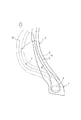
次に、図面を参照しつつこの発明の実施の形態を説明する。図1は、この発明に従う代表的な空気入りタイヤ(以下「タイヤ」という。)のタイヤ幅方向左半断面図である。 Next, embodiments of the present invention will be described with reference to the drawings. FIG. 1 is a left half sectional view in the tire width direction of a typical pneumatic tire (hereinafter referred to as “tire”) according to the present invention.
図1に示すタイヤ1は、ビードコア2を埋設した一対のビード部3と、ビード部3からタイヤ径方向外側に延びる一対のサイドウォール部4と、両サイドウォール部4に跨って延在するトレッド部5を具える。タイヤ1内にはビード部3、サイドウォール部4及びトレッド部5にわたってトロイド状に延びる少なくとも1枚のカーカスプライで構成されるカーカス6と、カーカス6のクラウン域外周にベルト層7が配設されている。カーカス6は、トレッド部5からサイドウォール部4を経てビード部3のビードコア2までトロイド状に延びるプライ本体部8と、このプライ本体部8から延びビードコア2の周りにタイヤ幅方向内側から外側に向かって折り返されたプライ折返し部9とからなる。
A tire 1 shown in FIG. 1 includes a pair of
カーカス6のプライ折返し部9は、そのタイヤ径方向外端である折返し端部10とリム径ラインRLの間をタイヤ径方向に沿って測定した距離L1が、タイヤ赤道面Eの上におけるカーカスプライ6の断面高さSHの0.4〜0.6倍の範囲内となる、すなわちL1/SH=0.4〜0.6となるように配置されている。これは、L1/SHを0.4未満と小さくすると、プライ折返し部9によるビード部2及びサイドウォール部4の補強効果が小さく、タイヤの撓み変形が大きくなる場合があるからである。また、特にオフロードで使用される重荷重用タイヤで、サイドウォール部のカット受傷が多いことから、折返し端部10の高さを高く設定することでプライ本体部8の破損を防ぐためでもある。しかし、L1/SHを0.6超と大きくすると、耐久性の向上に比して質量の増加が顕著となることから、L1/SHを0.6以下としている。
The ply turn-up portion 9 of the
発明者によるタイヤ変形解析の結果、図2に示すように、タイヤはビード部3からサイドウォール部4にかけての荷重直下で最も撓み変形を起こし、特にビードコア2からある距離の点(以下「変曲点P」という。)までの間はカーカスラインがタイヤ幅方向内側に凸状となる外曲げ変形を呈し、この変曲点Pからタイヤ径方向外側にある部分はカーカスラインがタイヤ幅方向外側に凸状となる内曲げ変形を呈することが分かった。そして、外曲げ変形を呈する部分では、プライ折返し部9が圧縮されており、タイヤ径方向外側に向かうにつれて圧縮歪が蓄積される結果、変曲点Pの近傍でプライ折返し部9が折れるというおそれがあった。一方、内曲げ変形を呈する部分では、プライ折返し部9が引っ張られており、内曲げ変形を呈する部分での圧縮歪の蓄積を低減する。しかし、完全に圧縮歪を相殺することはできず、プライ折返し端部10にまで圧縮歪が残るため、プライ折り返し端部10が周囲のタイヤ構成ゴムを押し上げることでプライ折り返し端部10の近傍に歪が集中して、亀裂が発生するおそれがある。
As a result of the tire deformation analysis by the inventor, as shown in FIG. 2, the tire is most flexed and deformed immediately under the load from the
そこで、この発明のタイヤ1では、カーカスプライ6の本体部8と折返し部9の間のゲージ厚と形状を適正化する、すなわちカーカス6のプライ本体部8とプライ折返し部9の間の距離Gが最小となる位置Qとリム径ラインRLの間をタイヤ径方向に沿って測定した距離L2を距離L1の1/3以下とすることでプライ折返し部9の圧縮を低減している。より詳細には、プライ折返し部9を、曲げの中立軸であり不伸長のプライ本体部8に近づけて配設することにより、プライ折返し部9の変形を抑制して、ビードコア2の上から発生するプライ折返し部9の圧縮を低減しているのである。この結果、プライ折返し部9の折れ及びプライ折返し端部10からの亀裂の発生を有効に防止することができ、ビード部耐久性が向上するのである。
Therefore, in the tire 1 of the present invention, the gauge thickness and shape between the
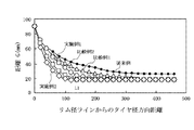
次に、距離L2を距離L1の1/3以下に設定した理由を説明する。発明者は、前記のようにプライ折返し部9をプライ本体部8に近づけて配設し、プライ折返し部9とプライ本体部の間のゲージ厚を小さくすることで、プライ折返し部9の圧縮を低減することを見出したが、単にゲージ厚を小さくしただけでは、必ずしも有効に耐久性が向上しない場合があった。そこで発明者は、さらにプライ折返し部9のカーカスライン形状の適正化についても鋭意研究を重ねた。まず、従来のカーカスライン形状を有する従来例のタイヤ、並びにカーカスのプライ本体部とプライ折返し部の間の距離Gが図3に示すような分布を有する比較例1及び2、実施例1及び2のタイヤを試作し、それぞれのタイヤにおける折返しプライの圧縮歪、折返し端部歪、プライ間歪の変化をFEM(Finite Element Method)により解析した。その結果を図4に示す。図4において、横軸はプライ折返し端部とリム径ラインの間の距離L1に対する位置Qとリム径ラインの間の距離L2の割合であり、縦軸は従来のタイヤの歪を100としたときのそれぞれの歪を指数化した値であり、値が大きいほど歪も大きい。位置Qを比較的高い位置とした比較例1及び2のタイヤでは、従来例のタイヤよりもプライ折返し部をプライ本体部に近づけることで圧縮歪及び折返し端部歪が低減しているが、プライ間歪はむしろ増加している。しかし、位置Qをビードコアに近づけ、距離L2を小さくしていくと、プライ間歪は徐々に減少し、距離L2が距離L1の1/3以下である実施例1及び2のタイヤでは、圧縮歪及び折返し端部歪に加え、プライ間歪も従来例のタイヤより小さくなることが分かった。
Next, the reason why the distance L2 is set to 1/3 or less of the distance L1 will be described. The inventor arranges the ply folding part 9 close to the
この発明はこれらの知見に基づいて完成されたものであり、これによれば、ワイヤーチェーファーやナイロンチェーファー等の付加的なビード部補強部材を使用することなく、カーカス折返し端でのコードの折れやカーカスの折返し端部から生ずる亀裂を有効に防止することができ、したがって軽量化と耐久性の向上を有効に両立することが可能となる。 The present invention has been completed based on these findings. According to this, the cord at the carcass folded end can be obtained without using an additional bead portion reinforcing member such as a wire chafer or a nylon chafer. It is possible to effectively prevent bending and cracks generated from the folded end portion of the carcass, and therefore it is possible to effectively achieve both weight reduction and improvement in durability.
さらに、カーカス6のプライ本体部8とプライ折返し部9の間の距離Gの最小値Gminは、ビードコア2に対応する領域におけるカーカス6のプライ本体部8とプライ折返し部9の間の最大距離をBWとして、0.15×BW<Gmin<0.25×BWの範囲内にあることが肝要である。これは、GminがBWの0.15倍以下の場合にはプライ間ゴムのせん断歪が大きくなり、プライ間セパレーションがプライ折返し端部の亀裂及びプライ折返し部の折れよりも早期に発生し、耐久性を有効に向上させることができないからである。一方、GminがBWの0.25倍以上の場合には、プライ折返し部の圧縮歪を十分に低減することができず、やはり耐久性を有効に向上させることができないからである。
Furthermore, the minimum value G min of the distance G between the
発明者は、さらに前記した変曲点Pのタイヤ径方向位置についても研究を重ね、一般にこれがプライ折返し端部10のとリム径ラインRLの間のタイヤ径方向距離L1の2/3倍の位置近傍となることを見出した。この変曲点Pよりタイヤ径方向内側の部分は外曲げ変形を呈する部分であり、プライ折返し部9が圧縮されるので、上述したような理由から、外曲げ変形を呈する部分、特に変曲点Pにおいて、カーカス6のプライ本体部8とプライ折返し部9の間の距離Gを、0.15×BW<G<0.25×BWの範囲内とすることが好ましい。
The inventor further researched the position of the inflection point P in the tire radial direction, and in general, this is a position that is 2/3 times the tire radial direction distance L1 between the ply turn-up
また、カーカス6のプライ本体部8とプライ折返し部9の間の距離Gは、リム径ラインRLからのタイヤ径方向距離が距離L1の2/3倍の位置とカーカスの折返し端部の間に漸増する部分を有することが好ましい。変曲点Pよりもタイヤ径方向外側の部分は内曲げ変形を呈する部分であり、プライ折返し部には引張り変形され、外曲げ変形を呈する部分からの圧縮の蓄積が軽減される領域である。したがって、プライ折返し部がより大きく引張り変形を受けるように、プライ折返し端部10にかけて距離Gを大きくすることが、耐久性の向上の観点から有利となる。
The distance G between the
距離Gが漸増に転じる位置Rのタイヤ径方向距離L3が耐久性に与える影響を評価するため、内曲げ変形を呈する部分のカーカスラインが図5に示すような形状である実施例2、4、5及び6のタイヤを試作し、それぞれのタイヤにおける折返しプライの圧縮歪、折返し端部歪、プライ間歪の変化をFEMにより解析した。その結果を図6に示す。図6において、横軸は距離L1に対する距離L3の割合であり、縦軸は各歪の大きさであり、破線で示された実施例2のタイヤの歪を基準としたときのそれぞれの歪を指数化した相対値として示してあり、値が大きいほど歪も大きい。内曲げ変形を呈する部分の距離Gを漸増させることが圧縮歪に与える影響はほとんどないが、L3/L1を2/3以上とすれば折返し端部歪及びプライ間歪を低減できることが分かる。
In order to evaluate the influence of the tire radial direction distance L3 of the position R where the distance G gradually increases on the durability, the carcass line of the portion exhibiting inward bending deformation has a shape as shown in FIG.
また、カーカス6のプライ本体部8とプライ折返し部9の間の距離Gは、カーカス6の折返し端部10にて、0.20×BW<G<0.30×BWの範囲内にあることが好ましい。これが0.20×BW以下では、内曲げ変形を呈する部分が十分に引張り変形されず、外曲げ変形を呈する部分からの圧縮の蓄積を軽減する効果の向上が不足する場合があるからであり、0.30×BW以上では、プライ折返し端部10におけるタイヤ表皮ゴムのゲージ厚が小さくなりすぎ、外傷からのプライ折返し端部10の保護が十分でなくなり、外傷による耐久性の低下が懸念されるからである。
In addition, the distance G between the
さらに、カーカス6のプライ本体部8とプライ折返し部9の間の距離Gは、リム径ラインRLからのタイヤ径方向距離が距離L1の1/3倍の位置と2/3倍の位置との間で略一定であることが好ましい。前記の通り、リム径ラインRLからのタイヤ径方向距離が距離L1の1/3倍の位置と2/3倍の位置との間の領域は外曲げ変形を呈する部分であり、ゲージ厚を極力小さくして圧縮の蓄積を最小限にすることが、耐久性向上の観点から有利だからである。但し、この領域のゲージ厚が小さすぎると、プライ本体部8とプライ折返し部9の間のゴム内でせん断歪が増加することから、前述したように距離Gを0.15×BWより大きくすることがさらに好ましい。
Further, the distance G between the
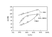
内曲げを呈する領域のゲージ厚の相違が耐久性に与える影響を評価するため、内曲げ変形を呈する部分のカーカスラインが図7に示すような形状である実施例2、5、7及び8のタイヤを試作し、それぞれのタイヤにおける折返しプライの圧縮歪、折返し端部歪、プライ間歪の変化をFEMにより解析した。その結果を図8に示す。図8において、横軸はリム径ラインRLからのタイヤ径方向距離が距離L1の2/3倍の位置におけるカーカスのプライ本体部とプライ折返し部の間の距離G2に対する、プライ折返し端部10におけるカーカスのプライ本体部とプライ折返し部の間の距離G3の割合であり、縦軸は各歪の大きさであり、破線で示された実施例2のタイヤの歪を基準としたときのそれぞれの歪を指数化した相対値として示してあり、値が大きいほど歪も大きい。内曲げ変形を呈する部分の距離が圧縮歪に与える影響はほとんどないが、プライ折返し端部10におけるカーカスのプライ本体部とプライ折返し部の間の距離G3を大きくすると、折返し端部歪及びプライ間歪が低減し、その効果はG3/G2が110%を超えると明確に現れることが分かる。したがって、耐久性を向上させる観点から、カーカス6の折返し端部10におけるカーカス6のプライ本体部8とプライ折返し部9の間の距離G3は、リム径ラインRLからのタイヤ径方向距離が距離L1の2/3倍の位置におけるカーカス6のプライ本体部8とプライ折返し部9の間の距離G2の1.10倍よりも大きいことが好ましい。
In order to evaluate the influence of the difference in gauge thickness in the region exhibiting inward bending on the durability, the carcass line of the portion exhibiting inward bending deformation is shaped as shown in FIG. Tires were prototyped, and changes in the compression strain, folded end portion strain, and inter-ply strain of the folded ply in each tire were analyzed by FEM. The result is shown in FIG. In FIG. 8, the horizontal axis represents the distance at the ply turn-up
なお、この発明のタイヤは、高荷重負荷条件下で使用される、例えば建設車両用や産業車両用等の重荷重用空気入りタイヤに適用すると、ビード部耐久性の向上が特に顕著である。 In addition, when the tire of this invention is applied to heavy-duty pneumatic tires, such as those for construction vehicles and industrial vehicles, which are used under high load conditions, the improvement in bead durability is particularly remarkable.
上述したところは、この発明の実施形態の一部を示したにすぎず、この発明の趣旨を逸脱しない限り、これらの構成を相互に組み合わせたり、種々の変更を加えたりすることができる。 The above description shows only some of the embodiments of the present invention, and these configurations can be combined with each other or various modifications can be made without departing from the spirit of the present invention.
次に、前記の従来例、比較例1、実施例2、実施例5及び実施例8のタイヤの耐久性の評価を行ったので、以下に説明する。 Next, the durability of the tires of the conventional example, comparative example 1, example 2, example 5, example 5 and example 8 was evaluated, which will be described below.
これら供試タイヤは、タイヤサイズが55/80R63の重荷重用タイヤであり、表1に示す諸元を有する。各供試タイヤを、リム幅41インチ(1.04メートル)のリムに組み付けタイヤ車輪を構成し、クラウン部の発熱を抑えるためにトレッドゴムを約30%まで削った。このタイヤ車輪に0.588MPa(相対圧)の内圧を適用し、雰囲気温度30℃、走行速度10km/h、タイヤ負荷荷重1450kN(TRA(EDI)で規定される正規荷重の160%に相当する。)の条件下で、横力0.1Gを付与しつつ、直径7.0mのドラム試験機上を走行させ、膨れやセパレーション等のビード部の損傷を感知するまで、又は走行時間が240時間に達するまでのいずれか早い時点まで走行を継続し、この走行時間からビード部耐久性を評価した。その評価結果を表1に示す。 These test tires are tires for heavy loads having a tire size of 55 / 80R63, and have the specifications shown in Table 1. Each test tire was assembled on a rim having a rim width of 41 inches (1.04 meters) to form a tire wheel, and tread rubber was shaved to about 30% in order to suppress heat generation at the crown. An internal pressure of 0.588 MPa (relative pressure) is applied to the tire wheel, which corresponds to an atmospheric temperature of 30 ° C., a traveling speed of 10 km / h, and a tire load of 1450 kN (160% of the normal load defined by TRA (EDI)). ) Running on a drum tester with a diameter of 7.0 m while applying a lateral force of 0.1 G, until the bead part is damaged such as swelling and separation, or the running time is 240 hours. The vehicle continued to travel until it reached the earlier point, and the bead durability was evaluated from this travel time. The evaluation results are shown in Table 1.

また、走行試験を終了したタイヤを切断し、タイヤ断面内での亀裂の有無とその大きさを目視により評価した。その結果、従来例のタイヤではプライ折返し部に破断が生じており、比較例1のタイヤではプライ間セパレーションが発生しており、実施例2のタイヤでは比較的大きなプライ間セパレーションが発生しており、実施例5のタイヤでは比較的小さなプライ間セパレーションが発生しており、実施例8のタイヤではセパレーション及び亀裂のいずれも発生していなかった。 Moreover, the tire which finished the driving | running | working test was cut | disconnected, and the presence or absence and the magnitude | size of the crack in a tire cross section were evaluated visually. As a result, in the tire of the conventional example, the ply turn-up portion is broken, the ply separation occurs in the tire of the comparative example 1, and the relatively large ply separation occurs in the tire of the example 2. In the tire of Example 5, a relatively small separation between plies occurred, and in the tire of Example 8, neither separation nor cracks occurred.
以上の結果から、実施例2、5及び8のタイヤは、従来例及び比較例1のタイヤよりもビード部耐久性が大幅に向上していることが分かる。また、実施例2、5、8の順にビード部耐久性が高いことが分かる。 From the above results, it can be seen that the tires of Examples 2, 5 and 8 have significantly improved bead durability compared to the tires of the conventional example and the comparative example 1. Moreover, it turns out that bead part durability is high in order of Example 2,5,8.
以上の説明から明らかなように、この発明によって、ワイヤーチェーファーやナイロンチェーファー等の付加的なビード部補強部材を使用することなく、カーカス折返し端でのコードの折れやカーカスの折返し端部から生ずる亀裂を有効に防止し、軽量化と耐久性の向上を有効に両立した空気入りタイヤを提供することが可能となった。 As is clear from the above description, according to the present invention, the cord bend at the carcass folded end and the folded end of the carcass can be used without using an additional bead reinforcing member such as a wire chafer or a nylon chafer. It has become possible to provide a pneumatic tire that effectively prevents cracks that occur and effectively achieves both weight reduction and improved durability.
1 タイヤ
2 ビードコア
3 ビード部
4 サイドウォール部
5 トレッド部
6 カーカス
7 ベルト層
8 プライ本体部
9 プライ折返し部
10 プライ折返し端部
E タイヤ赤道面
RL リム径ライン
DESCRIPTION OF SYMBOLS 1 Tire 2
Claims (7)
タイヤ幅方向断面にて、
前記カーカスのプライ折返し部のタイヤ径方向外端である折返し端部とリム径ラインの間をタイヤ径方向に沿って測定した距離L1が、タイヤ赤道面上におけるカーカスプライの断面高さの0.4〜0.6倍の範囲内にあり、
カーカスのプライ本体部とプライ折返し部の間の距離Gが最小となる位置とリム径ラインの間をタイヤ径方向に沿って測定した距離が前記距離L1の1/3以下であり、
前記カーカスのプライ本体部とプライ折返し部の間の距離Gの最小値G min は、ビードコアに対応する領域におけるカーカスのプライ本体部とプライ折返し部の間の最大距離をBWとして、0.15×BW<G min <0.25×BWの範囲内にあることを特徴とする空気入りタイヤ。 A ply body extending in a toroidal shape between the bead cores of the two bead portions from the tread portion through both side wall portions, and a ply folded back extending from the inner side in the tire width direction to the outer side extending from the ply body portion. In a pneumatic tire comprising a carcass composed of at least one carcass ply consisting of a portion,
In the tire width direction cross section,
The distance L1 measured along the tire radial direction between the folded end portion, which is the outer end in the tire radial direction of the ply folded portion of the carcass, and the rim diameter line is 0. 0 of the cross-sectional height of the carcass ply on the tire equatorial plane. In the range of 4 to 0.6 times,
Ri der 1/3 of the distance G is the distance that was measured between the position and the rim diameter line is minimum along the tire radial direction the distance L1 between the ply main body portion and the ply turnup portion of the carcass,
The minimum value G min of the distance G between the carcass ply body part and the ply folding part is 0.15 ×, where BW is the maximum distance between the carcass ply body part and the ply folding part in the region corresponding to the bead core. A pneumatic tire characterized by being in a range of BW <G min <0.25 × BW .
The pneumatic tire according to any one of claims 1 to 6 , wherein the pneumatic tire is a heavy duty pneumatic tire.
Priority Applications (1)
| Application Number | Priority Date | Filing Date | Title |
|---|---|---|---|
| JP2006015941A JP4945136B2 (en) | 2006-01-25 | 2006-01-25 | Pneumatic tire |
Applications Claiming Priority (1)
| Application Number | Priority Date | Filing Date | Title |
|---|---|---|---|
| JP2006015941A JP4945136B2 (en) | 2006-01-25 | 2006-01-25 | Pneumatic tire |
Publications (2)
| Publication Number | Publication Date |
|---|---|
| JP2007196781A JP2007196781A (en) | 2007-08-09 |
| JP4945136B2 true JP4945136B2 (en) | 2012-06-06 |
Family
ID=38451827
Family Applications (1)
| Application Number | Title | Priority Date | Filing Date |
|---|---|---|---|
| JP2006015941A Expired - Fee Related JP4945136B2 (en) | 2006-01-25 | 2006-01-25 | Pneumatic tire |
Country Status (1)
| Country | Link |
|---|---|
| JP (1) | JP4945136B2 (en) |
Families Citing this family (4)
| Publication number | Priority date | Publication date | Assignee | Title |
|---|---|---|---|---|
| JP5216304B2 (en) * | 2007-11-08 | 2013-06-19 | 株式会社ブリヂストン | Pneumatic tires for construction vehicles |
| ES2616804T3 (en) | 2010-08-05 | 2017-06-14 | Bridgestone Corporation | Tire |
| JP6785104B2 (en) * | 2015-10-02 | 2020-11-18 | 株式会社ブリヂストン | Tires for construction vehicles |
| WO2017057705A1 (en) * | 2015-10-02 | 2017-04-06 | 株式会社ブリヂストン | Tire for construction vehicles |
Family Cites Families (2)
| Publication number | Priority date | Publication date | Assignee | Title |
|---|---|---|---|---|
| JP3015340B2 (en) * | 1998-06-02 | 2000-03-06 | 住友ゴム工業株式会社 | Heavy load radial tire and method of manufacturing the same |
| US20040007305A1 (en) * | 2001-04-16 | 2004-01-15 | Kiyoshi Ueyoko | Pneumatic tire |
-
2006
- 2006-01-25 JP JP2006015941A patent/JP4945136B2/en not_active Expired - Fee Related
Also Published As
| Publication number | Publication date |
|---|---|
| JP2007196781A (en) | 2007-08-09 |
Similar Documents
| Publication | Publication Date | Title |
|---|---|---|
| JP5390392B2 (en) | Pneumatic tire | |
| JP5216304B2 (en) | Pneumatic tires for construction vehicles | |
| JP5671546B2 (en) | Pneumatic tire | |
| JP6052846B2 (en) | Pneumatic tire | |
| JP5683977B2 (en) | Agricultural tires | |
| JP2009286225A (en) | Pneumatic tire for heavy load | |
| JPWO2012017673A1 (en) | Pneumatic tire | |
| JP2012218528A (en) | Tire for heavy load | |
| JP5745539B2 (en) | Pneumatic tire | |
| JP5399778B2 (en) | Pneumatic tire | |
| WO2008072425A1 (en) | Heavy duty pneumatic radial tire | |
| JP3930474B2 (en) | Heavy duty tire | |
| WO2011043041A1 (en) | Pneumatic tire | |
| JP2010111370A (en) | Pneumatic tire | |
| WO2020122251A1 (en) | Pneumatic tire | |
| JP4763187B2 (en) | Pneumatic tire | |
| JP4945136B2 (en) | Pneumatic tire | |
| US9956827B2 (en) | Agricultural vehicle tire carcass reinforcement | |
| JP5670148B2 (en) | Heavy duty pneumatic tire | |
| JP3890050B2 (en) | Heavy duty tire | |
| JP4984662B2 (en) | Pneumatic tire | |
| JP4598504B2 (en) | Heavy duty pneumatic radial tire | |
| KR101385409B1 (en) | Truck and Bus Tire with Improved Bead Durability | |
| JP4763902B2 (en) | Pneumatic tire | |
| JP5859821B2 (en) | Pneumatic radial tire |
Legal Events
| Date | Code | Title | Description |
|---|---|---|---|
| A621 | Written request for application examination |
Free format text: JAPANESE INTERMEDIATE CODE: A621 Effective date: 20081216 |
|
| A977 | Report on retrieval |
Free format text: JAPANESE INTERMEDIATE CODE: A971007 Effective date: 20110427 |
|
| A131 | Notification of reasons for refusal |
Free format text: JAPANESE INTERMEDIATE CODE: A131 Effective date: 20110510 |
|
| A521 | Written amendment |
Free format text: JAPANESE INTERMEDIATE CODE: A523 Effective date: 20110711 |
|
| RD03 | Notification of appointment of power of attorney |
Free format text: JAPANESE INTERMEDIATE CODE: A7423 Effective date: 20110711 |
|
| TRDD | Decision of grant or rejection written | ||
| A01 | Written decision to grant a patent or to grant a registration (utility model) |
Free format text: JAPANESE INTERMEDIATE CODE: A01 Effective date: 20120207 |
|
| A01 | Written decision to grant a patent or to grant a registration (utility model) |
Free format text: JAPANESE INTERMEDIATE CODE: A01 |
|
| A61 | First payment of annual fees (during grant procedure) |
Free format text: JAPANESE INTERMEDIATE CODE: A61 Effective date: 20120305 |
|
| R150 | Certificate of patent or registration of utility model |
Ref document number: 4945136 Country of ref document: JP Free format text: JAPANESE INTERMEDIATE CODE: R150 Free format text: JAPANESE INTERMEDIATE CODE: R150 |
|
| FPAY | Renewal fee payment (event date is renewal date of database) |
Free format text: PAYMENT UNTIL: 20150309 Year of fee payment: 3 |
|
| R250 | Receipt of annual fees |
Free format text: JAPANESE INTERMEDIATE CODE: R250 |
|
| R250 | Receipt of annual fees |
Free format text: JAPANESE INTERMEDIATE CODE: R250 |
|
| R250 | Receipt of annual fees |
Free format text: JAPANESE INTERMEDIATE CODE: R250 |
|
| R250 | Receipt of annual fees |
Free format text: JAPANESE INTERMEDIATE CODE: R250 |
|
| R250 | Receipt of annual fees |
Free format text: JAPANESE INTERMEDIATE CODE: R250 |
|
| R250 | Receipt of annual fees |
Free format text: JAPANESE INTERMEDIATE CODE: R250 |
|
| LAPS | Cancellation because of no payment of annual fees |