EP2617073B1 - Rohrfeder zur aufnahme und zum vorspannen eines aktors - Google Patents
Rohrfeder zur aufnahme und zum vorspannen eines aktors Download PDFInfo
- Publication number
- EP2617073B1 EP2617073B1 EP11748952.6A EP11748952A EP2617073B1 EP 2617073 B1 EP2617073 B1 EP 2617073B1 EP 11748952 A EP11748952 A EP 11748952A EP 2617073 B1 EP2617073 B1 EP 2617073B1
- Authority
- EP
- European Patent Office
- Prior art keywords
- apertures
- tubular spring
- recesses
- spring
- actuator
- Prior art date
- Legal status (The legal status is an assumption and is not a legal conclusion. Google has not performed a legal analysis and makes no representation as to the accuracy of the status listed.)
- Active
Links
- 229910000639 Spring steel Inorganic materials 0.000 claims description 9
- 239000000446 fuel Substances 0.000 claims description 4
- 238000002485 combustion reaction Methods 0.000 claims description 3
- 239000002184 metal Substances 0.000 claims 1
- 238000004080 punching Methods 0.000 description 6
- 239000004033 plastic Substances 0.000 description 5
- 239000000919 ceramic Substances 0.000 description 2
- 238000002347 injection Methods 0.000 description 2
- 239000007924 injection Substances 0.000 description 2
- 238000000034 method Methods 0.000 description 2
- 239000004952 Polyamide Substances 0.000 description 1
- 238000005266 casting Methods 0.000 description 1
- 150000001875 compounds Chemical class 0.000 description 1
- 238000010276 construction Methods 0.000 description 1
- 238000005520 cutting process Methods 0.000 description 1
- 238000009826 distribution Methods 0.000 description 1
- 238000005553 drilling Methods 0.000 description 1
- 229920001971 elastomer Polymers 0.000 description 1
- 239000000806 elastomer Substances 0.000 description 1
- 238000009760 electrical discharge machining Methods 0.000 description 1
- 238000005516 engineering process Methods 0.000 description 1
- 238000004519 manufacturing process Methods 0.000 description 1
- 238000003801 milling Methods 0.000 description 1
- 229920002647 polyamide Polymers 0.000 description 1
- 238000004382 potting Methods 0.000 description 1
- 238000005096 rolling process Methods 0.000 description 1
- 238000003466 welding Methods 0.000 description 1
Images


Classifications
-
- F—MECHANICAL ENGINEERING; LIGHTING; HEATING; WEAPONS; BLASTING
- F16—ENGINEERING ELEMENTS AND UNITS; GENERAL MEASURES FOR PRODUCING AND MAINTAINING EFFECTIVE FUNCTIONING OF MACHINES OR INSTALLATIONS; THERMAL INSULATION IN GENERAL
- F16F—SPRINGS; SHOCK-ABSORBERS; MEANS FOR DAMPING VIBRATION
- F16F1/00—Springs
- F16F1/02—Springs made of steel or other material having low internal friction; Wound, torsion, leaf, cup, ring or the like springs, the material of the spring not being relevant
- F16F1/025—Springs made of steel or other material having low internal friction; Wound, torsion, leaf, cup, ring or the like springs, the material of the spring not being relevant characterised by having a particular shape
- F16F1/028—Springs made of steel or other material having low internal friction; Wound, torsion, leaf, cup, ring or the like springs, the material of the spring not being relevant characterised by having a particular shape cylindrical, with radial openings
-
- H—ELECTRICITY
- H10—SEMICONDUCTOR DEVICES; ELECTRIC SOLID-STATE DEVICES NOT OTHERWISE PROVIDED FOR
- H10N—ELECTRIC SOLID-STATE DEVICES NOT OTHERWISE PROVIDED FOR
- H10N30/00—Piezoelectric or electrostrictive devices
- H10N30/50—Piezoelectric or electrostrictive devices having a stacked or multilayer structure
- H10N30/508—Piezoelectric or electrostrictive devices having a stacked or multilayer structure adapted for alleviating internal stress, e.g. cracking control layers
-
- H—ELECTRICITY
- H10—SEMICONDUCTOR DEVICES; ELECTRIC SOLID-STATE DEVICES NOT OTHERWISE PROVIDED FOR
- H10N—ELECTRIC SOLID-STATE DEVICES NOT OTHERWISE PROVIDED FOR
- H10N30/00—Piezoelectric or electrostrictive devices
- H10N30/80—Constructional details
- H10N30/88—Mounts; Supports; Enclosures; Casings
- H10N30/886—Additional mechanical prestressing means, e.g. springs
-
- F—MECHANICAL ENGINEERING; LIGHTING; HEATING; WEAPONS; BLASTING
- F02—COMBUSTION ENGINES; HOT-GAS OR COMBUSTION-PRODUCT ENGINE PLANTS
- F02M—SUPPLYING COMBUSTION ENGINES IN GENERAL WITH COMBUSTIBLE MIXTURES OR CONSTITUENTS THEREOF
- F02M51/00—Fuel-injection apparatus characterised by being operated electrically
- F02M51/06—Injectors peculiar thereto with means directly operating the valve needle
- F02M51/0603—Injectors peculiar thereto with means directly operating the valve needle using piezoelectric or magnetostrictive operating means
Definitions
- the invention relates to a tube spring for receiving and biasing a piezoelectric or magnetostrictive actuator according to the preamble of claim 1 and an actuator unit according to claim 10 with a corresponding tube spring.
- piezoelectric or magnetostrictive actuators are usually used in actuator units, for example, to actuate fuel injection valves of internal combustion engines.
- actuators are usually biased by a spring.
- springs are usually designed as a tubular spring, which serve as a hollow body for receiving the actuator.
- a corresponding Bourdon tube is for example from the WO 00/08353 A1 known.
- the tubular spring shown there is designed as an elastic hollow body, which biases the piezoelectric actuator therein.
- the hollow body is provided with recesses which are bone-shaped and extend transversely to the hollow body axis.
- the Bourdon tube is made of spring steel strip from which first the recesses are punched out and then individual blanks from the spring steel band are cut to the desired size for the Bourdon tube. Subsequently, the blanks are rolled so that form two adjacent abutting edges in the longitudinal direction of the tube spring. To fix the tube spring, these abutting edges are welded or fixed by upper and lower cover plates, so that the abutting edges abut each other. Especially with non-welded adjacent Impact edges can lead to uneven loads and deformations in the Bourdon tube.
- a bourdon tube which also has bone-shaped recesses perpendicular to the longitudinal axis of the bourdon tube, which are spaced apart by webs between the recesses. Depending on their position, the webs have different distances, so that uneven mechanical loads on the tubular spring, in particular starting from the two non-welded abutting edges, are distributed as evenly as possible in the circumferential direction on the tubular spring structure.
- Object of the present invention is therefore to provide a Bourdon tube for receiving and biasing a piezoelectric or magnetostrictive actuator of an actuator, which is particularly suitable for actuating a fuel injector for internal combustion engines and the uneven loads and deformations in the Bourdon both in the longitudinal be kept as low as possible in the transverse direction.
- the Bourdon tube according to the invention has a number of recesses, which are usually punched out of a spring steel blank. After rolling the spring, the recesses extend from the outer upper surface of the Bourdon tube to the inner surface.
- Each recess has a cross-sectional contour line on one of the two surfaces, the outer surface or the inner surface. On each surface side, the cross-sectional contact line defines in each case a maximum longitudinal extent of the recess and in each case a maximum transverse extent, wherein the transverse extent is aligned substantially perpendicular to the longitudinal extent.
- the cross-sectional contour lines on the outer surface and on the inner surface in a common projection plane may not be congruent, so that the maximum longitudinal extent and / or the maximum transverse extent of the recess on the outer surface of that of the inner surface different.
- the transverse dimensions of two recesses already differ from one another on the same of the two surfaces of the tubular spring.
- portions of the Bourdon tube may be structurally strengthened or weakened to more evenly distribute the stresses and deformations within the Bourdon tube both circumferentially and along the longitudinal axis of the Bourdon tube.
- the web width between the individual recesses in the transverse direction can be kept constant.
- the maximum longitudinal extent of a recess is at least substantially aligned transversely to the tube spring axis.
- the cross-sectional contour lines of the recesses are rounded off at the respective ends in the longitudinal direction and can preferably be described by a radius.
- the recesses are preferably made first by punching the recesses of a spring steel blank, rounded, writable by a radius recess ends are particularly easy to manufacture, since compared to, for example, angled ends less errors in shape, for example by punching burrs occur.
- the recesses of different transverse expansions accordingly also have different radii of their ends in the longitudinal direction.
- a recess with a larger transverse extent correspondingly has a larger radius at its longitudinal end than a recess of smaller transverse extent.
- two or more recesses each having different transverse dimensions are arranged within a series of recesses to compensate for at least circumferentially uneven loads in the Bourdon tube over the circumference of the tube.
- two or more recesses each having different transverse dimensions are arranged in a plurality of rows of recesses, so that unequal transverse and longitudinal loads in the Bourdon tube can be evenly distributed over the entire Bourdon tube structure in the best possible way.
- the at least two or more recesses alternate along a series of recesses in each case.
- FIG. 1 shows a sectional view through a piezoelectric actuator unit 1, which is particularly useful as a drive unit for actuating an injection nozzle in a fuel injector.
- the piezoelectric actuator unit 1 has an actuator module 2, which is composed of several hundred piezoelectric ceramic layers in the form of a stack actuator. Between each two ceramic layers, an inner electrode is arranged, which alternately with two on the outer wall of the Actuator module 2 vertically extending outer electrodes is electrically connected. Furthermore, two Mullismespins 7 are arranged parallel to the two outer electrodes, which are contacted via corresponding lines with the two outer electrodes.
- the actuator module 2 with the wired two Kunststoff Kunststoffspins 7 in a plastic sleeve (mounting sleeve) 5 is inserted and fixed.
- the plastic sleeve 5 is simultaneously formed as a casting mold in which the components 2, 7 are cast with a potting compound 9, for example, with a Vergusssilikon, elastomer or the like.
- the plastic sleeve 5 is made of a plastic, for example made of a PA plastic (polyamide).
- a top plate 3 is arranged, which is non-positively connected to the actuator module 2.
- the top plate 3 thus limits the actuator module 2 upwards.
- two insulated bushings for the two Mais michellesspins 7 are designed so that the protruding ends of the twomaschinessenspins 7 can be later connected to the electrical supply of the actuator module 2 to a control voltage of a corresponding control unit.
- the lower end of the actuator module 2 is bounded by a bottom plate 4, which is also non-positively connected to the actuator module 2.
- a tube spring 8 is sleeve-shaped and surrounds the molded actuator module 2.
- the tube spring 8 is mounted with a biasing force acting on the actuator module 2 as a restoring force and thus a provision of the non-actuated actuator module 2 in its normal position supported.
- the entire assembly is sheathed by an actuator housing 6 sleeve-shaped.
- the upper end of the actuator housing 6 is fixedly and sealingly connected to the top plate 3.
- the lower end of the actuator housing 6, however, is axially movable relative to the bottom plate 4, but also sealed fuel-tight.
- a small, axial lifting movement thus arises between the bottom plate 4 and the underside of the actuator housing 6, which can be used to control a servo valve, a nozzle needle or the like.
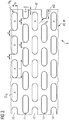
- FIGS. 2A and 2B show the structure of a known Bourdon tube 8.
- the bourdon has over its entire surface except for the edge regions to which the cover plates 3, 4 are fixed, uniformly distributed recesses A, which are formed in the embodiment shown bone-shaped and transverse to the axis through the Bourdon tube run.
- the recesses A ensure sufficient elasticity of the preloaded piezoelectric actuator 2 receiving coil spring 8, so that the tube spring obstructs the caused by applying a voltage to the piezoelectric actuator 2 elongation of the actuator 2 in the longitudinal direction only slightly.
- the elasticity of the Bourdon tube 2 can be adjusted by the number and length of the recesses A to the desired elongation of the biased piezoelectric actuator 2.
- FIGS. 2A and 2B shown arrangement of the recesses A offset one above the other.
- This arrangement ensures optimum elasticity of the tube spring while sufficient strength to apply the bias voltage to the piezoelectric actuator 2 can.
- the elasticity is particularly supported by the bone-shaped form of the recesses A in this embodiment, in which two circular recesses are connected to each other via a slot.
- preferred Size ranges are in the circular recesses at diameters of 0.8 mm to 1.6 mm and at the intervals between the centers of the recesses in the range of 1.5 mm to 3.5 mm.
- This shape can also be very simple and accurate form eg by punching in a spring steel sheet.
- the tube spring is preferably made of a spring steel strip with a thickness of 0.5 mm.
- the recesses A are punched into the spring steel strip.
- the spring steel strip is cut to the desired size for the tube spring 8, wherein the recesses A are preferably cut through in the middle. Then the blank is rolled, wherein the cutting or punching edges are oriented outwards. Subsequently, the edges are deburred and fixed the tube shape with a preferably produced by a laser longitudinal weld. Instead of a fixation of the tubular shape by welding, a fixation can also be done by the upper and lower cover plates 3, 4, so that the abutting edges abut only against each other.
- FIG. 2B shows a sectional view of the tube spring 8 according to FIG. 2A , Shown is an example of a recess A and the outer surface 40 and the inner surface 41 of the tube spring eighth
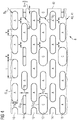
- FIG. 3 shows a section of a known tube spring 8 in the unrolled state. Shown is one compared to the FIGS. 2A and 2B alternative embodiment of the recesses A, in which the recesses A have a rectangular basic shape, which are rounded at the two-sided ends of the recesses A and there can be described by a radius R A.
- the recesses A will be in their outer shape on each one of the surfaces 41, 42 described by their cross-sectional contour line CL. Consequently, the cross-sectional contour line CL at the two-sided ends of the recesses A in the radius R A over.
- the cross-sectional contour line CL defines a maximum transverse extent h A of the recesses A.
- the recesses A are arranged spaced apart in the circumferential direction of the tube spring 8 by webs of width a, wherein the web width a may also be constant in particular; alternatively but also variable.
- the recesses A are halved in their longitudinal extent, so that the two half recesses in the finished tube spring 8 across the abutting edge each form a recess A; and thus equal to the other recesses A, which are not arranged at the abutting edge.
- the illustrated embodiment of a tubular spring 8 has only one variant of recesses A, each having both the same maximum longitudinal extent 1 and a maximum transverse extent h A.
- FIG. 4 A first embodiment of a Bourdon tube 8 according to the invention is shown.
- embodiment of the bourdon tube 8 are in addition to the recesses A and recesses B with a maximum transverse extent h B along the bourdon tube circumference arranged in row 11. Circumferentially alternate the recesses A and B, wherein over the abutting edges of two corresponding half recesses one Form recess B.
- the recesses B are each rounded at their longitudinal ends.
- the curves can be described by a radius R B , which is smaller than the corresponding radius R A a recess of the type A.
- R B a radius
- recesses of a type C in the tube spring 8 whose maximum transverse extent h C greater than that maximum transverse extent h A of the recesses of type A are.
- These recesses B are also arranged alternately with recesses of the type A along the circumference of the tube spring 8 (on the outer surface 41 or inner surface 42).
- a recess of the type C is also arranged in series 13 over the abutting edge 42.
- the recesses of the type C have rounded end regions, which can be described by a radius R C , where R C > R A.
- FIG. 5 shows an alternative embodiment of a Bourdon tube 8.
- recesses of types B and C are arranged only on the abutting edge 42 away. In the presentation of the FIG. 5 this only applies to the rows 11 and 13, in which recesses B and C, respectively, are arranged over the abutting edge 42.
- the bourdon tube 8 according to this embodiment has on each surface side 40, 41 exclusively recesses of type A. By an arrangement of recesses of different types on the abutting edge 42 away the introduced at the abutting edges uneven loads on the tube spring 8 are already distributed as uniformly as possible in the longitudinal and transverse direction of the bourdon tube 8 at its source.
- the invention is not limited to the two embodiments of the FIGS. 4 and 5 limited.
- other arrangements of recesses of various For example, more than three recesses of different types, each having a different maximum transverse extent in the context of this invention can be used.
Landscapes
- Engineering & Computer Science (AREA)
- General Engineering & Computer Science (AREA)
- Mechanical Engineering (AREA)
- Fuel-Injection Apparatus (AREA)
Description
- Die Erfindung betrifft eine Rohrfeder zur Aufnahme und zum Vorspannen eines piezoelektrischen oder magnetostriktiven Aktors nach dem Oberbegriff des Anspruchs 1 und eine Aktoreinheit gemäß Anspruch 10 mit einer entsprechenden Rohrfeder.
- In der Kraftfahrzeugtechnik werden üblicherweise piezoelektrische oder magnetostriktive Aktoren in Aktoreinheiten verwendet, um beispielsweise Brennstoffeinspritzventile von Brennkraftmaschinen zu betätigen. Zur Vermeidung oder zumindest Reduzierung von Zug- und / oder Scherkräften werden solche Aktoren zumeist durch eine Feder vorgespannt. Solche Federn sind zumeist als Rohrfeder ausgebildet, die als Hohlkörper zur Aufnahme des Aktors dienen.
- Eine entsprechende Rohrfeder ist beispielsweise aus der
WO 00/08353 A1 - Aus der
DE 10 344 621 A1 ist eine Rohrfeder bekannt, die ebenfalls knochenförmige Ausnehmungen senkrecht zur Längsachse der Rohrfeder aufweist, die durch Stege zwischen den Ausnehmungen voneinander beabstandet sind. Die Stege weisen je nach ihrer Position unterschiedliche Abstände auf, so dass sich ungleichmäßige mechanische Belastungen der Rohrfeder insbesondere ausgehend von den beiden nicht verschweißten Stoßkanten möglichst gleichmäßig in Umfangsrichtung auf die Rohrfederstruktur verteilen. - Weitere Vorrichtungen nach dem Stand der Technik sind aus
WO 2004 / 097208 A1 ,EP 1 605 159 A1 undEP 1 519 072 A1 bekannt. - Ausgehend von den beiden Stoßkanten der Rohrfeder, insbesondere, wenn diese nicht verschweißt sind, ergeben sich jedoch nicht nur ungleichmäßige Belastungen und Verformungen entlang des Umfangs der Rohrfeder, sondern auch in deren Längsrichtung, so dass ein Verteilen von ungleichmäßigen Querkräften in Umfangsrichtung der Rohrfeder, wie in der
DE 10 344 621 gezeigt, nur einen Teil der auftretenden ungleichmäßigen Belastungen innerhalb der Rohrfeder ausgleicht. - Aufgabe der vorliegenden Erfindung ist es deshalb, eine Rohrfeder zur Aufnahme und zum Vorspannen eines piezoelektrischen oder magnetostriktiven Aktors einer Aktoreinheit bereitzustellen, welche insbesondere zur Betätigung eines Brennstoffeinspritzventils für Brennkraftmaschinen geeignet ist und bei der ungleichmäßige Belastungen und Verformungen in der Rohrfeder sowohl in deren Längs- als auch in deren Querrichtung möglichst gering gehalten werden.
- Diese Aufgabe wird gelöst durch eine Rohrfeder mit den Merkmalen gemäß Anspruch 1.
- Die erfindungsgemäße Rohrfeder weist eine Reihe von Ausnehmungen auf, die üblicherweise aus einem Federstahl-Rohling ausgestanzt werden. Nach Rollen der Feder reichen die Ausnehmungen von der Außenobenfläche der Rohrfeder bis zur Innenoberfläche. Jede Ausnehmung weist an einer der beiden Oberflächen, der Außenoberfläche oder der Innenoberfläche, eine Querschnittskonturlinie auf. Auf jeweils einer Oberflächenseite legt die Querschnittskontorlinie jeweils eine maximale Längsausdehnung der Ausnehmung sowie jeweils eine maximale Querausdehnung fest, wobei die Querausdehnung im Wesentlichen senkrecht zur Längsausdehnung ausgerichtet ist. Je nach verwendetem Stanzwerkzeug und je nach verwendetem Stanzverfahren können die Querschnittskonturlinien auf der Außenoberfläche und auf der Innenoberfläche in einer gemeinsamen Projektionsebene ggf. nicht deckungsgleich sein, so dass sich die maximale Längsausdehnung und / oder die maximale Querausdehnung der Ausnehmung auf der Außenoberfläche von derjenigen der Innenoberfläche unterscheidet.
- Erfindungsgemäß unterscheiden sich die Querausdehnungen zweier Ausnehmungen jedoch bereits auf derselben der beiden Oberflächen der Rohrfeder voneinander. Auf diese Weise können Bereiche der Rohrfeder strukturell gestärkt oder geschwächt werden, um die Belastungen und Verformungen innerhalb der Rohrfeder gleichmäßiger sowohl auf den Umfang als auch entlang der Längsachse der Rohrfeder verteilt werden. Die Stegbreite zwischen den einzelnen Ausnehmungen in Querrichtung kann dabei konstant gehalten werden.
- Üblicherweise ist die maximale Längsausdehnung einer Ausnehmung zumindest im Wesentlichen quer zur Rohrfederachse ausgerichtet.
- Vorteilhafterweise sind die Querschnittskonturlinien der Ausnehmungen an den jeweiligen Enden in Längsrichtung abgerundet und können vorzugsweise durch einen Radius beschrieben werden. Da die Ausnehmungen vorzugsweise zunächst durch Stanzen der Ausnehmungen aus einem Federstahl-Zuschnitt hergestellt werden, sind abgerundete, durch einen Radius beschreibbare Ausnehmungs-Enden besonders einfach herzustellen, da im Vergleich zu beispielsweise gewinkelten Enden weniger Formfehler beispielsweise durch Stanzgrate, auftreten können. Vorteilhafterweise weisen die Ausnehmungen verschiedener Querausdehnungen entsprechend auch unterschiedliche Radien ihrer Enden in Längsrichtung auf. Eine Ausnehmung mit größerer Querausdehnung weist entsprechend einen größeren Radius an ihrem Längsende auf als eine Ausnehmung kleinerer Querausdehnung.
- Vorteilhafterweise sind innerhalb einer Reihe von Ausnehmungen zwei oder mehr Ausnehmungen jeweils verschiedener Querausdehnungen angeordnet, um zumindest in Umfangsrichtung ungleichmäßige Belastungen in der Rohrfeder über den Rohrfederumfang auszugleichen. Vorzugsweise sind zwei oder mehr Ausnehmungen jeweils verschiedener Querausdehnungen in mehreren Reihen von Ausnehmungen angeordnet, so dass ungleiche Quer- und Längsbelastungen in der Rohrfeder bestmöglich über die gesamt Rohrfederstruktur gleichmäßig verteilt werden können.
- Besonders vorteilhafterweise wechseln sich die zumindest zwei oder mehr Ausnehmungen entlang einer Reihe von Ausnehmungen jeweils ab.
- Da sich insbesondere die ungleichmäßigen Belastungen in der Rohrfeder von den beiden Stoßkanten ausgehend über die Rohrfeder verteilen, kann es weiterhin von Vorteil sein, wenn sich solche Ausnehmungen, die über die Stoßkanten hinweg verlaufen und folglich durch die beiden Stoßkanten geteilt werden, längs der Rohrfederachse jeweils in ihren Querschnittsausdehnungen unterscheiden. Beispielsweise können in Längsrichtung der Rohrfeder entlang der Stoßkanten aufeinanderfolgende Ausnehmungen abwechselnd unterschiedliche Endradien aufweisen. So wird besonderes effektiv eine ungleichmäßige Belastung, die an den Stoßkanten an die Rohrfeder eingebracht wird, bereits am Ort des Entstehens möglichst gleichmäßig entlang der gesamten Längsrichtung der Rohrfeder verteilt werden.
- Die hier aufgeführten Ausführungsformen können zudem in beliebiger Weise auch untereinander kombiniert werden. Ausfüh-Die hier aufgeführten Ausführungsformen können zudem in beliebiger Weise auch untereinander kombiniert werden. Ausführungsbeispiele sind im Folgenden anhand von schematischen Zeichnungen erläutert. Es zeigen:
- Figur 1
- ein Schnittbild durch eine piezoelektrische Aktoreinheit,
- Figur 2A
- eine Ausführungsform eines bekannten Hohlkörpers zum Vorspannen eines piezoelektrischen Aktors als Rohrfeder,
- Figur 2B
- eine Schnittansicht der Rohrfeder gemäß
Figur 2A , - Figur 3
- einen Ausschnitt aus einer bekannten Rohrfeder im ausgerollten Zustand,
- Figur 4
- eine erste Ausführungsform einer erfindungsgemäßen Rohrfeder,
- Figur 5
- eine zweite Ausführungsform einer erfindungsgemäßen Rohrfeder,
- Elemente gleicher Konstruktion oder Funktion sind figurenübergreifend mit den gleichen Bezugszeichen versehen.
-
Figur 1 zeigt ein Schnittbild durch eine piezoelektrische Aktoreinheit 1, die insbesondere als Antriebseinheit zur Betätigung einer Einspritzdüse in einem Kraftstoffinjektor verwendbar ist. Die piezoelektrische Aktoreinheit 1 weist ein Aktormodul 2 auf, das aus mehreren hundert piezoelektrischen Keramikschichten in Form eines Stapelaktors aufgebaut ist. Zwischen jeweils zwei Keramikschichten ist eine Innenelektrode angeordnet, die wechselweise mit zwei an der Außenwand des Aktormoduls 2 vertikal verlaufenden Außenelektroden elektrisch leitend verbunden ist. Des Weiteren sind parallel zu den beiden Außenelektroden zwei Kontaktierungspins 7 angeordnet, die über entsprechende Leitungen mit den beiden Außenelektroden kontaktiert sind. Zur Montage wird das Aktormodul 2 mit den verdrahteten beiden Kontaktierungspins 7 in eine Kunststoffhülse (Montagehülse) 5 eingesetzt und fixiert. Die Kunststoffhülse 5 ist gleichzeitig als Gussform ausgebildet, in der die eingesetzten Bauteile 2,7 mit einer Vergussmasse 9, beispielsweise mit einem Vergusssilikon, Elastomer oder ähnlichem vergossen werden. Die Kunststoffhülse 5 ist aus einem Kunststoff, beispielsweise aus einem PA-Kunststoff (Polyamid) gefertigt. - An einem oberen Ende des Aktormoduls 2 ist eine Kopfplatte 3 angeordnet, die mit dem Aktormodul 2 kraftschlüssig verbunden ist. Die Kopfplatte 3 begrenzt somit das Aktormodul 2 nach oben. In der Kopfplatte 3 sind zwei isolierte Durchführungen für die beiden Kontaktierungspins 7 so ausgeführt, dass die herausragenden Enden der beiden Kontaktierungspins 7 später zur elektrischen Versorgung des Aktormoduls 2 an eine Steuerspannung eines entsprechenden Steuergerätes angeschlossen werden können.
- Das untere Ende des Aktormoduls 2 wird von einer Bodenplatte 4 begrenzt, die ebenfalls mit dem Aktormodul 2 kraftschlüssig verbunden ist. Zwischen der Kopfplatte 3 und der Bodenplatte 4 ist eine Rohrfeder 8 hülsenförmig angeordnet und umschließt das vergossene Aktormodul 2. Die Rohrfeder 8 wird mit einer Vorspannkraft montiert, die auf das Aktormodul 2 als Rückstellkraft wirkt und somit eine Rückstellung des nicht angesteuerten Aktormoduls 2 in seine Grundstellung unterstützt.
- Die ganze Baugruppe wird von einem Aktorgehäuse 6 hülsenförmig ummantelt. Das obere Ende des Aktorgehäuses 6 ist dabei mit der Kopfplatte 3 fest und abdichtend verbunden. Das untere Ende des Aktorgehäuses 6 ist dagegen gegenüber der Bodenplatte 4 axial beweglich angeordnet, aber ebenfalls kraftstoffdicht abgedichtet. Bei Ansteuerung des Aktormoduls 2 entsteht somit zwischen der Bodenplatte 4 und der Unterseite des Aktorgehäuses 6 eine geringe, axiale Hubbewegung, die zur Steuerung eines Servoventils, einer Düsennadel oder dergleichen genutzt werden kann.
-
Figuren 2A und 2B zeigen den Aufbau einer bekannten Rohrfeder 8. Die Rohrfeder weist über seine gesamte Fläche bis auf die Randbereiche, an denen die Abdeckplatten 3, 4 befestigt werden, gleichmäßig verteilt Ausnehmungen A auf, die in dem gezeigten Ausführungsbeispiel knochenförmig ausgebildet sind und quer zur Achse durch die Rohrfeder verlaufen. Die Ausnehmungen A gewährleisten eine ausreichende Elastizität der den vorgespannten piezoelektrischen Aktor 2 aufnehmenden Rohrfeder 8, so dass die Rohrfeder die durch ein Anlegen einer Spannung an den piezoelektrischen Aktor 2 hervorgerufene Längung des Aktors 2 in Längsrichtung nur unwesentlich behindert. Die Elastizität der Rohrfeder 2 kann dabei durch die Anzahl und die Länge der Ausnehmungen A an die gewünschte Längendehnung des vorgespannten piezoelektrischen Aktors 2 angepasst werden. - Vorteilhaft ist hierbei auch die in den
Figuren 2A und 2B gezeigte Anordnung der Ausnehmungen A versetzt übereinander. Diese Anordnung gewährleistet eine optimale Elastizität der Rohrfeder bei gleichzeitiger ausreichender Festigkeit, um die Vorspannung auf den piezoelektrischen Aktor 2 aufbringen zu können. Die Elastizität wird insbesondere auch durch die knochenförmige Form der Ausnehmungen A in diesem Ausführungsbeispiel unterstützt, bei der zwei kreisförmige Aussparungen über einen Schlitz miteinander verbunden sind. Bevorzugte Größenbereiche liegen bei den kreisförmigen Aussparungen bei Durchmessern von 0,8 mm bis 1,6 mm und bei den Abständen zwischen den Mittelpunkten der Aussparungen im Bereich von 1,5 mm bis 3,5 mm. Diese Form lässt sich weiterhin sehr einfach und genau z.B. durch Stanzen in einem Federstahlblech ausbilden. - Die Rohrfeder wird vorzugsweise aus einem Federstahlband mit einer Dicke von 0,5 mm gefertigt. In einem ersten Schritt werden dabei in das Federstahlband die Ausnehmungen A eingestanzt. Alternativ besteht auch die Möglichkeit, die Ausnehmungen durch Drahterodieren, Fräsen, Bohren oder mit elektrochemischen Verfahren auszubilden.
- Nach dem Ausbilden der Ausnehmungen A wird das Federstahlband auf das für die Rohrfeder 8 gewünschte Maß zugeschnitten, wobei die Ausnehmungen A vorzugsweise mittig durchgeschnitten sind. Dann wird der Zuschnitt gerollt, wobei die Schnitt- bzw. Stanzkanten nach außen orientiert sind. Anschließend werden die Kanten entgratet und die Rohrform mit einer vorzugsweise durch einen Laser erzeugten Längs-Schweißnaht fixiert. Statt einer Fixierung der Rohrform durch Schweißen kann eine Fixierung auch durch die oberen und unteren Abdeckplatten 3, 4 erfolgen, so dass die Stoßkanten nur aneinander anliegen.
-
Figur 2B zeigt eine Schnittbilddarstellung der Rohrfeder 8 gemäßFigur 2A . Dargestellt ist exemplarisch eine Ausnehmung A sowie die Außenoberfläche 40 und die Innenoberfläche 41 der Rohrfeder 8. -
Figur 3 zeigt einen Ausschnitt aus einer bekannten Rohrfeder 8 im ausgerollten Zustand. Dargestellt ist eine im Vergleich zu denFiguren 2A und 2B alternative Ausführungsform der Ausnehmungen A, bei der die Ausnehmungen A eine rechteckige Grundform aufweisen, die an den beidseitigen Enden der Ausnehmungen A abgerundet sind und dort durch einen Radius RA beschrieben werden können. Die Ausnehmungen A werden in ihrer äußeren Form auf je einer der Oberflächen 41, 42 durch ihre Querschnittskonturlinie CL beschrieben. Folglich geht die Querschnittskonturlinie CL an den beidseitigen Enden der Ausnehmungen A in den Radius RA über. - Senkrecht zur Längsausrichtung der Ausnehmungen A legt die Querschnittskonturlinie CL eine maximale Querausdehnung hA der Ausnehmungen A fest. Die Ausnehmungen A sind in Umfangsrichtung der Rohrfeder 8 durch Stege der Breite a voneinander beabstandet angeordnet, wobei die Stegbreite a insbesondere auch konstant sein kann; alternativ aber auch variabel.
- Dargestellt ist ebenfalls eine Stoßkante 42 der Rohrfeder 8. Vorzugweise werden hier die Ausnehmungen A in ihrer Längsausdehnung halbiert, so dass die beiden halben Ausnehmungen bei der fertigen Rohrfeder 8 über die Stoßkante hinweg jeweils eine Ausnehmung A bilden; und somit gleich zu den übrigen Ausnehmungen A, die nicht an der Stoßkante angeordnet sind.
- Die gezeigte Ausführungsform einer Rohrfeder 8 weist nur eine Variante von Ausnehmungen A auf, die jeweils sowohl die gleiche maximale Längsausdehnung 1 als auch eine maximale Querausdehnung hA aufweisen.
- In analoger Darstellung wie
Figur 3 zeigt dieFigur 4 eine erste Ausführungsform für eine erfindungsgemäße Rohrfeder 8. Dargestellt sind Ausnehmungen A des ersten Typs mit einer maximalen Querausdehnung hA in den Reihen 10, 12, 14, jeweils verteilt entlang des Umfangs einer Außen- oder Innenoberfläche 41, 42 der Rohrfeder 8. Gemäß dieser erfindungsgemäßen Ausführungsform der Rohrfeder 8 sind zusätzlich zu den Ausnehmungen A auch Ausnehmungen B mit einer maximalen Querausdehnung hB entlang des Rohrfederumfangs angeordnet, in Reihe 11. Umlaufend wechseln sich die Ausnehmungen A und B jeweils ab, wobei über die Stoßkanten hinweg zwei entsprechende halbe Ausnehmungen eine Ausnehmung B bilden. - Auch die Ausnehmungen B sind an ihren längsseitigen Enden jeweils abgerundet. Die Rundungen lassen sich durch einen Radius RB beschreiben, der kleiner ist als der entsprechende Radius RA einer Ausnehmung des Typs A. Zusätzlich sind beispielsweise in Reihe 13 Ausnehmungen eines Typs C in der Rohrfeder 8 angeordnet, deren maximale Querausdehnung hC größer als die maximale Querausdehnung hA der Ausnehmungen des Typs A sind. Auch diese Ausnehmungen B sind entlang des Umfangs der Rohrfeder 8 (auf der Außenoberfläche 41 oder Innenoberfläche 42) jeweils abwechselnd mit Ausnehmungen des Typs A angeordnet. Analog zur Anordnung in Reihe 11 ist auch in Reihe 13 eine Ausnehmung des Typs C über die Stoßkante 42 hinweg angeordnet.
- Auch die Ausnehmungen des Typs C weisen abgerundete Endbereiche auf, die durch einen Radius RC beschrieben werden können, wobei RC > RA.
- In Reihe 15 sind Ausnehmungen aller drei dargestellten Typen A, B und C angeordnet.
-
Figur 5 zeigt eine alternative Ausführungsform einer erfindungsgemäßen Rohrfeder 8. In dieser Ausführungsform sind nur über die Stoßkante 42 hinweg Ausnehmungen der Typen B und C angeordnet. In der Darstellung derFigur 5 betrifft dies nur die Reihen 11 und 13, in denen Ausnehmungen B bzw. C über die Stoßkante 42 hinweg angeordnet sind. Im Übrigen weist die Rohrfeder 8 gemäß dieser Ausführungsform auf jeweils einer Oberflächenseite 40, 41 ausschließlich Ausnehmungen des Typs A auf. Durch eine Anordnung von Ausnehmungen unterschiedlichen Typs über die Stoßkante 42 hinweg werden die an den Stoßkanten eingebrachten ungleichmäßigen Belastungen auf die Rohrfeder 8 bereits an ihrem Entstehungsort möglichst gleichmäßig in Längs- und Querrichtung der Rohrfeder 8 verteilt. - Die Erfindung ist jedoch selbstverständlich nicht auf die beiden Ausführungsformen der
Figuren 4 und5 beschränkt. Alternativ können auch andere Anordnungen von Ausnehmungen verschiedener maximaler Querausdehnungen in einer Rohrfeder 8 verwirklicht werden, beispielsweise können auch mehr als drei Ausnehmungen verschiedenen Typs, mit jeweils verschiedener maximaler Querausdehnung im Sinne dieser Erfindung eingesetzt werden.
Claims (7)
- Rohrfeder (8) zur Aufnahme und zum Vorspannen eines piezoelektrischen oder magnetostriktiven Aktors (2) einer Aktoreinheit (1),
welche insbesondere zur Betätigung eines Brennstoffeinspritzventils für Brennkraftmaschinen geeignet ist,
mit mehreren Reihen (9, 10, 11, 12, 13) von Ausnehmungen (A, B, C), die jeweils von der Außenoberfläche (40) der Rohrfeder (8) bis zu deren Innenoberfläche (41) reichen, wobei- die Ausnehmungen (A, B, C) auf jeder der beiden Oberflächenseiten eine jeweilige Querschnittskonturlinie aufweisen und durch diese Querschnittskonturlinie (CLA, CLB, CLc)- jeweils eine maximale Längsausdehnung (Länge 1) einer Ausnehmung (A, B, C) sowie- jeweils eine maximale Querausdehnung (Breite hA, hB, hC), die im Wesentlichen senkrecht zur Längsausdehnung ausgerichtet ist,definiert wird,- sich zumindest die jeweiligen maximalen Querausdehnungen (hA, hB, hC) zweier Ausnehmungen (A,B,C) auf derselben der beiden Oberflächen (40,41) der Rohrfeder (8) voneinander unterscheiden und- die Rohrfeder (2) zwei Stoßkanten (42) aufweist, die einander zugeordnet sind und sich über die gesamte Länge der Rohrfeder erstrecken,dadurch gekennzeichnet, dass
entlang der Stoßkanten (42) Ausnehmungen (A, B, C) unterschiedlicher maximaler Querausdehnungen angeordnet sind, die sich über die Stoßkanten hinweg erstrecken. - Rohrfeder nach Anspruch 1,
dadurch gekennzeichnet, dass
die Querschnittskonturlinien (CLA, CLB, CLC) der Ausnehmungen (A, B, C) an den in Längsrichtung beiden Enden der Ausnehmungen (A, B, C) jeweils abgerundet sind. - Rohrfeder nach Anspruch 2,
dadurch gekennzeichnet, dass
die Querschnittskonturlinien (CLA, CLB, CLC) der Ausnehmungen (A, B, C) an den jeweils beiden Enden in Längsrichtung durch jeweils einen Radius (RA, RB, RC) beschrieben werden können. - Rohrfeder nach Anspruch 3,
dadurch gekennzeichnet, dass
die Ausnehmungen (A, B, C) verschiedener Querausdehnungen (hA, hB, hC) entsprechend verschiedene Radien (RA, RB, RC) an ihren Enden aufweisen. - Rohrfeder (8) nach einem der vorhergehenden Ansprüche, dadurch gekennzeichnet, dass
zumindest innerhalb einer Reihe zwei oder mehr Ausnehmungen jeweils verschiedener Querausdehnungen (hA, hB, hC) angeordnet sind. - Rohrfeder (8) nach einem der vorhergehenden Ansprüche, dadurch gekennzeichnet, dass
sich zumindest zwei oder mehr Ausnehmungen entlang der Reihenachse abwechseln. - Rohrfeder (8) nach einem der vorhergehenden Ansprüche, dadurch gekennzeichnet, dass- die Rohrfeder (8) aus Metall gefertigt ist, insbesondere aus Federstahl, und- die Ausnehmungen (41) eingestanzt sind.
Applications Claiming Priority (2)
| Application Number | Priority Date | Filing Date | Title |
|---|---|---|---|
| DE102010040773.9A DE102010040773B4 (de) | 2010-09-14 | 2010-09-14 | Rohrfeder zur Aufnahme und zum Vorspannen eines Aktors |
| PCT/EP2011/064709 WO2012034837A1 (de) | 2010-09-14 | 2011-08-26 | Rohrfeder zur aufnahme und zum vorspannen eines aktors |
Publications (2)
| Publication Number | Publication Date |
|---|---|
| EP2617073A1 EP2617073A1 (de) | 2013-07-24 |
| EP2617073B1 true EP2617073B1 (de) | 2017-12-27 |
Family
ID=44512906
Family Applications (1)
| Application Number | Title | Priority Date | Filing Date |
|---|---|---|---|
| EP11748952.6A Active EP2617073B1 (de) | 2010-09-14 | 2011-08-26 | Rohrfeder zur aufnahme und zum vorspannen eines aktors |
Country Status (4)
| Country | Link |
|---|---|
| US (1) | US9627604B2 (de) |
| EP (1) | EP2617073B1 (de) |
| DE (1) | DE102010040773B4 (de) |
| WO (1) | WO2012034837A1 (de) |
Families Citing this family (3)
| Publication number | Priority date | Publication date | Assignee | Title |
|---|---|---|---|---|
| DE102010040773B4 (de) | 2010-09-14 | 2017-03-30 | Continental Automotive Gmbh | Rohrfeder zur Aufnahme und zum Vorspannen eines Aktors |
| DE102016013721A1 (de) * | 2016-11-17 | 2018-05-17 | Grammer Ag | Feder, Verwendung eines Kunststoffschlauchs als Feder und Ausstattungsteil eines Fahrzeuginnenraums |
| WO2019140371A1 (en) | 2018-01-15 | 2019-07-18 | Cts Corporation | Pre-loaded piezoelectric stack actuator |
Citations (1)
| Publication number | Priority date | Publication date | Assignee | Title |
|---|---|---|---|---|
| EP1519072A1 (de) * | 2003-09-25 | 2005-03-30 | Robert Bosch Gmbh | Rohrfeder für Aktor |
Family Cites Families (11)
| Publication number | Priority date | Publication date | Assignee | Title |
|---|---|---|---|---|
| US2171185A (en) | 1935-12-18 | 1939-08-29 | Maier Friedrich Eugen | Longitudinal spring for telescopic tubular guides |
| AU7709975A (en) | 1974-01-16 | 1976-07-08 | Saturnini E | Cage-like spring |
| US4958101A (en) | 1988-08-29 | 1990-09-18 | Toyota Jidosha Kabushiki Kaisha | Piezoelectric actuator |
| RU2093805C1 (ru) * | 1996-03-26 | 1997-10-20 | Тюменский государственный нефтегазовый университет | Манометрическая трубчатая пружина |
| US6135234A (en) * | 1997-01-02 | 2000-10-24 | Gas Research Institute | Dual mode multiple-element resonant cavity piezoceramic borehole energy source |
| US6494288B1 (en) * | 1998-04-28 | 2002-12-17 | Schlumberger Technology Corporation | Acoustic logging tool |
| US6984924B1 (en) | 1998-08-06 | 2006-01-10 | Siemens Aktiengesellschaft | Piezoelectric actuator unit |
| DE10319600A1 (de) * | 2003-05-02 | 2004-11-18 | Robert Bosch Gmbh | Aktoreinheit für ein piezogesteuertes Kraftstoffeinspritzventil |
| DE102004011455A1 (de) | 2003-06-04 | 2004-12-30 | Robert Bosch Gmbh | Rohrfeder für Aktor und Verfahren zur Montage der Rohrfeder |
| DE102004028209A1 (de) * | 2004-06-09 | 2005-12-29 | Robert Bosch Gmbh | Kraftstoffeinspritzventil |
| DE102010040773B4 (de) | 2010-09-14 | 2017-03-30 | Continental Automotive Gmbh | Rohrfeder zur Aufnahme und zum Vorspannen eines Aktors |
-
2010
- 2010-09-14 DE DE102010040773.9A patent/DE102010040773B4/de not_active Expired - Fee Related
-
2011
- 2011-08-26 US US13/823,533 patent/US9627604B2/en active Active
- 2011-08-26 WO PCT/EP2011/064709 patent/WO2012034837A1/de active Application Filing
- 2011-08-26 EP EP11748952.6A patent/EP2617073B1/de active Active
Patent Citations (1)
| Publication number | Priority date | Publication date | Assignee | Title |
|---|---|---|---|---|
| EP1519072A1 (de) * | 2003-09-25 | 2005-03-30 | Robert Bosch Gmbh | Rohrfeder für Aktor |
Also Published As
| Publication number | Publication date |
|---|---|
| WO2012034837A1 (de) | 2012-03-22 |
| EP2617073A1 (de) | 2013-07-24 |
| US9627604B2 (en) | 2017-04-18 |
| DE102010040773A1 (de) | 2012-03-15 |
| DE102010040773B4 (de) | 2017-03-30 |
| US20140145563A1 (en) | 2014-05-29 |
Similar Documents
| Publication | Publication Date | Title |
|---|---|---|
| EP1021662B1 (de) | Piezoelektrische aktoreinheit | |
| EP1636486B1 (de) | Aktoreinheit für ein piezogesteuertes kraftstoffeinspritzventil | |
| EP1434952B1 (de) | Verfahren zur herstellung einer rohrfeder | |
| WO1999008330A1 (de) | Vorgespannter piezoelektrischer aktor | |
| EP2617073B1 (de) | Rohrfeder zur aufnahme und zum vorspannen eines aktors | |
| EP1623468B1 (de) | Aktoreinheit für ein piezoelektrisch gesteuertes kraftstoffeinspritzventil | |
| DE3206126A1 (de) | Verfahren zum herstellen eines waermebehandelten lagerringes und nach diesem verfahren hergestellter lagerring | |
| EP1519072B1 (de) | Rohrfeder für Aktor | |
| EP2047530B1 (de) | Federelement sowie piezoaktor mit dem federelement | |
| EP1384273B1 (de) | Vorrichtung zum übertragen einer auslenkung eines aktors | |
| WO2003019688A2 (de) | Hülsenförmiger hohlkörper für ein piezoaktormodul sowie verfahren zu dessen herstellung | |
| DE102013220507B4 (de) | Vorrichtung und Verfahren zur Erzeugung einer nicht zylindrischen Innenfläche einer Bohrung | |
| DE10319599A1 (de) | Aktoreinheit für ein piezogesteuertes Kraftstoffeinspritzventil | |
| EP1630408B1 (de) | Kraftstoffinjektor für eine Brennkraftmaschine sowie Verfahren zur Montage eines derartigen Kraftstoffinjektors | |
| EP1590880B1 (de) | Vorrichtung zum bertragen einer auslenkung eines aktors | |
| DE102017111697A1 (de) | Lageranordnung | |
| WO2013098155A1 (de) | Hebelvorrichtung und einspritzventil | |
| EP3839988B1 (de) | Stellvorrichtung | |
| DE102004039591B4 (de) | Hochdruck-Einspritzinjektor für Brennkraftmaschinen | |
| EP2079117A2 (de) | Piezoaktormodul mit mehreren Piezoaktoren und ein Verfahren zu dessen Herstellung | |
| EP2041811A2 (de) | Elektromechanischer stellantrieb | |
| DE10154634A1 (de) | Piezoelement und ein Verfahren zu dessen Herstellung | |
| EP1664524A1 (de) | VENTILEINRICHTUNG, INSBESONDERE EIN KRAFTSTOFFEINSPRITZVENTIL FÜR EINE BRENNKRAFTMASCHINE | |
| DE10319586A1 (de) | Aktoreinheit für ein piezogesteuertes Kraftstoffeinspritzventil | |
| DE10064831A1 (de) | Mehrreihiges Wälzlager |
Legal Events
| Date | Code | Title | Description |
|---|---|---|---|
| PUAI | Public reference made under article 153(3) epc to a published international application that has entered the european phase |
Free format text: ORIGINAL CODE: 0009012 |
|
| 17P | Request for examination filed |
Effective date: 20130415 |
|
| AK | Designated contracting states |
Kind code of ref document: A1 Designated state(s): AL AT BE BG CH CY CZ DE DK EE ES FI FR GB GR HR HU IE IS IT LI LT LU LV MC MK MT NL NO PL PT RO RS SE SI SK SM TR |
|
| DAX | Request for extension of the european patent (deleted) | ||
| 17Q | First examination report despatched |
Effective date: 20161118 |
|
| GRAP | Despatch of communication of intention to grant a patent |
Free format text: ORIGINAL CODE: EPIDOSNIGR1 |
|
| RIC1 | Information provided on ipc code assigned before grant |
Ipc: F02M 51/06 20060101ALN20170629BHEP Ipc: F16F 1/02 20060101ALI20170629BHEP Ipc: H01L 41/053 20060101AFI20170629BHEP |
|
| INTG | Intention to grant announced |
Effective date: 20170721 |
|
| GRAS | Grant fee paid |
Free format text: ORIGINAL CODE: EPIDOSNIGR3 |
|
| GRAA | (expected) grant |
Free format text: ORIGINAL CODE: 0009210 |
|
| AK | Designated contracting states |
Kind code of ref document: B1 Designated state(s): AL AT BE BG CH CY CZ DE DK EE ES FI FR GB GR HR HU IE IS IT LI LT LU LV MC MK MT NL NO PL PT RO RS SE SI SK SM TR |
|
| REG | Reference to a national code |
Ref country code: GB Ref legal event code: FG4D Free format text: NOT ENGLISH |
|
| REG | Reference to a national code |
Ref country code: CH Ref legal event code: EP |
|
| REG | Reference to a national code |
Ref country code: AT Ref legal event code: REF Ref document number: 959007 Country of ref document: AT Kind code of ref document: T Effective date: 20180115 |
|
| REG | Reference to a national code |
Ref country code: IE Ref legal event code: FG4D Free format text: LANGUAGE OF EP DOCUMENT: GERMAN |
|
| REG | Reference to a national code |
Ref country code: DE Ref legal event code: R096 Ref document number: 502011013508 Country of ref document: DE |
|
| PG25 | Lapsed in a contracting state [announced via postgrant information from national office to epo] |
Ref country code: LT Free format text: LAPSE BECAUSE OF FAILURE TO SUBMIT A TRANSLATION OF THE DESCRIPTION OR TO PAY THE FEE WITHIN THE PRESCRIBED TIME-LIMIT Effective date: 20171227 Ref country code: FI Free format text: LAPSE BECAUSE OF FAILURE TO SUBMIT A TRANSLATION OF THE DESCRIPTION OR TO PAY THE FEE WITHIN THE PRESCRIBED TIME-LIMIT Effective date: 20171227 Ref country code: NO Free format text: LAPSE BECAUSE OF FAILURE TO SUBMIT A TRANSLATION OF THE DESCRIPTION OR TO PAY THE FEE WITHIN THE PRESCRIBED TIME-LIMIT Effective date: 20180327 |
|
| REG | Reference to a national code |
Ref country code: NL Ref legal event code: MP Effective date: 20171227 |
|
| REG | Reference to a national code |
Ref country code: LT Ref legal event code: MG4D |
|
| PG25 | Lapsed in a contracting state [announced via postgrant information from national office to epo] |
Ref country code: LV Free format text: LAPSE BECAUSE OF FAILURE TO SUBMIT A TRANSLATION OF THE DESCRIPTION OR TO PAY THE FEE WITHIN THE PRESCRIBED TIME-LIMIT Effective date: 20171227 Ref country code: RS Free format text: LAPSE BECAUSE OF FAILURE TO SUBMIT A TRANSLATION OF THE DESCRIPTION OR TO PAY THE FEE WITHIN THE PRESCRIBED TIME-LIMIT Effective date: 20171227 Ref country code: HR Free format text: LAPSE BECAUSE OF FAILURE TO SUBMIT A TRANSLATION OF THE DESCRIPTION OR TO PAY THE FEE WITHIN THE PRESCRIBED TIME-LIMIT Effective date: 20171227 Ref country code: GR Free format text: LAPSE BECAUSE OF FAILURE TO SUBMIT A TRANSLATION OF THE DESCRIPTION OR TO PAY THE FEE WITHIN THE PRESCRIBED TIME-LIMIT Effective date: 20180328 Ref country code: BG Free format text: LAPSE BECAUSE OF FAILURE TO SUBMIT A TRANSLATION OF THE DESCRIPTION OR TO PAY THE FEE WITHIN THE PRESCRIBED TIME-LIMIT Effective date: 20180327 |
|
| PG25 | Lapsed in a contracting state [announced via postgrant information from national office to epo] |
Ref country code: NL Free format text: LAPSE BECAUSE OF FAILURE TO SUBMIT A TRANSLATION OF THE DESCRIPTION OR TO PAY THE FEE WITHIN THE PRESCRIBED TIME-LIMIT Effective date: 20171227 |
|
| PG25 | Lapsed in a contracting state [announced via postgrant information from national office to epo] |
Ref country code: CZ Free format text: LAPSE BECAUSE OF FAILURE TO SUBMIT A TRANSLATION OF THE DESCRIPTION OR TO PAY THE FEE WITHIN THE PRESCRIBED TIME-LIMIT Effective date: 20171227 Ref country code: SK Free format text: LAPSE BECAUSE OF FAILURE TO SUBMIT A TRANSLATION OF THE DESCRIPTION OR TO PAY THE FEE WITHIN THE PRESCRIBED TIME-LIMIT Effective date: 20171227 Ref country code: EE Free format text: LAPSE BECAUSE OF FAILURE TO SUBMIT A TRANSLATION OF THE DESCRIPTION OR TO PAY THE FEE WITHIN THE PRESCRIBED TIME-LIMIT Effective date: 20171227 Ref country code: CY Free format text: LAPSE BECAUSE OF FAILURE TO SUBMIT A TRANSLATION OF THE DESCRIPTION OR TO PAY THE FEE WITHIN THE PRESCRIBED TIME-LIMIT Effective date: 20171227 Ref country code: ES Free format text: LAPSE BECAUSE OF FAILURE TO SUBMIT A TRANSLATION OF THE DESCRIPTION OR TO PAY THE FEE WITHIN THE PRESCRIBED TIME-LIMIT Effective date: 20171227 |
|
| REG | Reference to a national code |
Ref country code: FR Ref legal event code: PLFP Year of fee payment: 8 |
|
| PG25 | Lapsed in a contracting state [announced via postgrant information from national office to epo] |
Ref country code: IS Free format text: LAPSE BECAUSE OF FAILURE TO SUBMIT A TRANSLATION OF THE DESCRIPTION OR TO PAY THE FEE WITHIN THE PRESCRIBED TIME-LIMIT Effective date: 20180427 Ref country code: RO Free format text: LAPSE BECAUSE OF FAILURE TO SUBMIT A TRANSLATION OF THE DESCRIPTION OR TO PAY THE FEE WITHIN THE PRESCRIBED TIME-LIMIT Effective date: 20171227 Ref country code: SM Free format text: LAPSE BECAUSE OF FAILURE TO SUBMIT A TRANSLATION OF THE DESCRIPTION OR TO PAY THE FEE WITHIN THE PRESCRIBED TIME-LIMIT Effective date: 20171227 Ref country code: IT Free format text: LAPSE BECAUSE OF FAILURE TO SUBMIT A TRANSLATION OF THE DESCRIPTION OR TO PAY THE FEE WITHIN THE PRESCRIBED TIME-LIMIT Effective date: 20171227 Ref country code: PL Free format text: LAPSE BECAUSE OF FAILURE TO SUBMIT A TRANSLATION OF THE DESCRIPTION OR TO PAY THE FEE WITHIN THE PRESCRIBED TIME-LIMIT Effective date: 20171227 |
|
| PG25 | Lapsed in a contracting state [announced via postgrant information from national office to epo] |
Ref country code: MT Free format text: LAPSE BECAUSE OF FAILURE TO SUBMIT A TRANSLATION OF THE DESCRIPTION OR TO PAY THE FEE WITHIN THE PRESCRIBED TIME-LIMIT Effective date: 20171227 |
|
| REG | Reference to a national code |
Ref country code: DE Ref legal event code: R097 Ref document number: 502011013508 Country of ref document: DE |
|
| PLBE | No opposition filed within time limit |
Free format text: ORIGINAL CODE: 0009261 |
|
| STAA | Information on the status of an ep patent application or granted ep patent |
Free format text: STATUS: NO OPPOSITION FILED WITHIN TIME LIMIT |
|
| PG25 | Lapsed in a contracting state [announced via postgrant information from national office to epo] |
Ref country code: DK Free format text: LAPSE BECAUSE OF FAILURE TO SUBMIT A TRANSLATION OF THE DESCRIPTION OR TO PAY THE FEE WITHIN THE PRESCRIBED TIME-LIMIT Effective date: 20171227 |
|
| 26N | No opposition filed |
Effective date: 20180928 |
|
| PG25 | Lapsed in a contracting state [announced via postgrant information from national office to epo] |
Ref country code: SI Free format text: LAPSE BECAUSE OF FAILURE TO SUBMIT A TRANSLATION OF THE DESCRIPTION OR TO PAY THE FEE WITHIN THE PRESCRIBED TIME-LIMIT Effective date: 20171227 |
|
| PG25 | Lapsed in a contracting state [announced via postgrant information from national office to epo] |
Ref country code: MC Free format text: LAPSE BECAUSE OF FAILURE TO SUBMIT A TRANSLATION OF THE DESCRIPTION OR TO PAY THE FEE WITHIN THE PRESCRIBED TIME-LIMIT Effective date: 20171227 |
|
| REG | Reference to a national code |
Ref country code: CH Ref legal event code: PL |
|
| GBPC | Gb: european patent ceased through non-payment of renewal fee |
Effective date: 20180826 |
|
| PG25 | Lapsed in a contracting state [announced via postgrant information from national office to epo] |
Ref country code: CH Free format text: LAPSE BECAUSE OF NON-PAYMENT OF DUE FEES Effective date: 20180831 Ref country code: LU Free format text: LAPSE BECAUSE OF NON-PAYMENT OF DUE FEES Effective date: 20180826 Ref country code: LI Free format text: LAPSE BECAUSE OF NON-PAYMENT OF DUE FEES Effective date: 20180831 |
|
| REG | Reference to a national code |
Ref country code: BE Ref legal event code: MM Effective date: 20180831 |
|
| PG25 | Lapsed in a contracting state [announced via postgrant information from national office to epo] |
Ref country code: BE Free format text: LAPSE BECAUSE OF NON-PAYMENT OF DUE FEES Effective date: 20180831 |
|
| REG | Reference to a national code |
Ref country code: AT Ref legal event code: MM01 Ref document number: 959007 Country of ref document: AT Kind code of ref document: T Effective date: 20180826 |
|
| PG25 | Lapsed in a contracting state [announced via postgrant information from national office to epo] |
Ref country code: GB Free format text: LAPSE BECAUSE OF NON-PAYMENT OF DUE FEES Effective date: 20180826 |
|
| PG25 | Lapsed in a contracting state [announced via postgrant information from national office to epo] |
Ref country code: AT Free format text: LAPSE BECAUSE OF NON-PAYMENT OF DUE FEES Effective date: 20180826 |
|
| PG25 | Lapsed in a contracting state [announced via postgrant information from national office to epo] |
Ref country code: TR Free format text: LAPSE BECAUSE OF FAILURE TO SUBMIT A TRANSLATION OF THE DESCRIPTION OR TO PAY THE FEE WITHIN THE PRESCRIBED TIME-LIMIT Effective date: 20171227 |
|
| PG25 | Lapsed in a contracting state [announced via postgrant information from national office to epo] |
Ref country code: HU Free format text: LAPSE BECAUSE OF FAILURE TO SUBMIT A TRANSLATION OF THE DESCRIPTION OR TO PAY THE FEE WITHIN THE PRESCRIBED TIME-LIMIT; INVALID AB INITIO Effective date: 20110826 Ref country code: PT Free format text: LAPSE BECAUSE OF FAILURE TO SUBMIT A TRANSLATION OF THE DESCRIPTION OR TO PAY THE FEE WITHIN THE PRESCRIBED TIME-LIMIT Effective date: 20171227 |
|
| REG | Reference to a national code |
Ref country code: DE Ref legal event code: R081 Ref document number: 502011013508 Country of ref document: DE Owner name: VITESCO TECHNOLOGIES GMBH, DE Free format text: FORMER OWNER: CONTINENTAL AUTOMOTIVE GMBH, 30165 HANNOVER, DE |
|
| PG25 | Lapsed in a contracting state [announced via postgrant information from national office to epo] |
Ref country code: MK Free format text: LAPSE BECAUSE OF NON-PAYMENT OF DUE FEES Effective date: 20171227 Ref country code: SE Free format text: LAPSE BECAUSE OF FAILURE TO SUBMIT A TRANSLATION OF THE DESCRIPTION OR TO PAY THE FEE WITHIN THE PRESCRIBED TIME-LIMIT Effective date: 20171227 Ref country code: IE Free format text: LAPSE BECAUSE OF NON-PAYMENT OF DUE FEES Effective date: 20180826 |
|
| PG25 | Lapsed in a contracting state [announced via postgrant information from national office to epo] |
Ref country code: AL Free format text: LAPSE BECAUSE OF FAILURE TO SUBMIT A TRANSLATION OF THE DESCRIPTION OR TO PAY THE FEE WITHIN THE PRESCRIBED TIME-LIMIT Effective date: 20171227 |
|
| REG | Reference to a national code |
Ref country code: DE Ref legal event code: R084 Ref document number: 502011013508 Country of ref document: DE |
|
| REG | Reference to a national code |
Ref country code: DE Ref legal event code: R081 Ref document number: 502011013508 Country of ref document: DE Owner name: VITESCO TECHNOLOGIES GMBH, DE Free format text: FORMER OWNER: VITESCO TECHNOLOGIES GMBH, 30165 HANNOVER, DE |
|
| REG | Reference to a national code |
Ref country code: DE Ref legal event code: R079 Ref document number: 502011013508 Country of ref document: DE Free format text: PREVIOUS MAIN CLASS: H01L0041053000 Ipc: H10N0030880000 |
|
| P01 | Opt-out of the competence of the unified patent court (upc) registered |
Effective date: 20230530 |
|
| PGFP | Annual fee paid to national office [announced via postgrant information from national office to epo] |
Ref country code: FR Payment date: 20230824 Year of fee payment: 13 Ref country code: DE Payment date: 20230831 Year of fee payment: 13 |