EP2616592B1 - Composite material, component suitable for use in composite material and related methods and structures - Google Patents
Composite material, component suitable for use in composite material and related methods and structures Download PDFInfo
- Publication number
- EP2616592B1 EP2616592B1 EP20110776821 EP11776821A EP2616592B1 EP 2616592 B1 EP2616592 B1 EP 2616592B1 EP 20110776821 EP20110776821 EP 20110776821 EP 11776821 A EP11776821 A EP 11776821A EP 2616592 B1 EP2616592 B1 EP 2616592B1
- Authority
- EP
- European Patent Office
- Prior art keywords
- component
- drainage
- composite material
- suitably
- members
- Prior art date
- Legal status (The legal status is an assumption and is not a legal conclusion. Google has not performed a legal analysis and makes no representation as to the accuracy of the status listed.)
- Active
Links
- 239000002131 composite material Substances 0.000 title claims description 55
- 238000000034 method Methods 0.000 title claims description 34
- 239000012530 fluid Substances 0.000 claims description 61
- 239000000463 material Substances 0.000 claims description 35
- 238000004519 manufacturing process Methods 0.000 claims description 14
- 230000008878 coupling Effects 0.000 claims description 9
- 238000010168 coupling process Methods 0.000 claims description 9
- 238000005859 coupling reaction Methods 0.000 claims description 9
- 238000004891 communication Methods 0.000 claims description 5
- 238000003825 pressing Methods 0.000 claims description 4
- 230000004044 response Effects 0.000 claims description 4
- 239000002689 soil Substances 0.000 description 8
- XLYOFNOQVPJJNP-UHFFFAOYSA-N water Substances O XLYOFNOQVPJJNP-UHFFFAOYSA-N 0.000 description 8
- 239000004753 textile Substances 0.000 description 6
- 238000003466 welding Methods 0.000 description 5
- 238000010586 diagram Methods 0.000 description 4
- 238000009434 installation Methods 0.000 description 4
- 239000007789 gas Substances 0.000 description 3
- 230000037361 pathway Effects 0.000 description 3
- 230000008569 process Effects 0.000 description 3
- 239000000853 adhesive Substances 0.000 description 2
- 230000001070 adhesive effect Effects 0.000 description 2
- 230000000694 effects Effects 0.000 description 2
- 239000000835 fiber Substances 0.000 description 2
- 238000010348 incorporation Methods 0.000 description 2
- 239000007788 liquid Substances 0.000 description 2
- 239000012528 membrane Substances 0.000 description 2
- 238000010008 shearing Methods 0.000 description 2
- 239000000758 substrate Substances 0.000 description 2
- 239000004743 Polypropylene Substances 0.000 description 1
- 230000002411 adverse Effects 0.000 description 1
- 230000004888 barrier function Effects 0.000 description 1
- 239000004927 clay Substances 0.000 description 1
- 238000013461 design Methods 0.000 description 1
- 229920001903 high density polyethylene Polymers 0.000 description 1
- 239000004700 high-density polyethylene Substances 0.000 description 1
- 238000007689 inspection Methods 0.000 description 1
- 230000035699 permeability Effects 0.000 description 1
- 239000004033 plastic Substances 0.000 description 1
- 229920003023 plastic Polymers 0.000 description 1
- -1 polypropylene Polymers 0.000 description 1
- 229920001155 polypropylene Polymers 0.000 description 1
- 239000011435 rock Substances 0.000 description 1
- 239000007787 solid Substances 0.000 description 1
- 239000000126 substance Substances 0.000 description 1
- 238000013022 venting Methods 0.000 description 1
- 239000002699 waste material Substances 0.000 description 1
- 238000009941 weaving Methods 0.000 description 1
Images


Classifications
-
- F—MECHANICAL ENGINEERING; LIGHTING; HEATING; WEAPONS; BLASTING
- F17—STORING OR DISTRIBUTING GASES OR LIQUIDS
- F17D—PIPE-LINE SYSTEMS; PIPE-LINES
- F17D1/00—Pipe-line systems
-
- B—PERFORMING OPERATIONS; TRANSPORTING
- B09—DISPOSAL OF SOLID WASTE; RECLAMATION OF CONTAMINATED SOIL
- B09C—RECLAMATION OF CONTAMINATED SOIL
- B09C1/00—Reclamation of contaminated soil
- B09C1/005—Extraction of vapours or gases using vacuum or venting
-
- E—FIXED CONSTRUCTIONS
- E02—HYDRAULIC ENGINEERING; FOUNDATIONS; SOIL SHIFTING
- E02D—FOUNDATIONS; EXCAVATIONS; EMBANKMENTS; UNDERGROUND OR UNDERWATER STRUCTURES
- E02D17/00—Excavations; Bordering of excavations; Making embankments
- E02D17/20—Securing of slopes or inclines
- E02D17/202—Securing of slopes or inclines with flexible securing means
-
- E—FIXED CONSTRUCTIONS
- E02—HYDRAULIC ENGINEERING; FOUNDATIONS; SOIL SHIFTING
- E02D—FOUNDATIONS; EXCAVATIONS; EMBANKMENTS; UNDERGROUND OR UNDERWATER STRUCTURES
- E02D31/00—Protective arrangements for foundations or foundation structures; Ground foundation measures for protecting the soil or the subsoil water, e.g. preventing or counteracting oil pollution
- E02D31/002—Ground foundation measures for protecting the soil or subsoil water, e.g. preventing or counteracting oil pollution
- E02D31/004—Sealing liners
-
- E—FIXED CONSTRUCTIONS
- E02—HYDRAULIC ENGINEERING; FOUNDATIONS; SOIL SHIFTING
- E02D—FOUNDATIONS; EXCAVATIONS; EMBANKMENTS; UNDERGROUND OR UNDERWATER STRUCTURES
- E02D31/00—Protective arrangements for foundations or foundation structures; Ground foundation measures for protecting the soil or the subsoil water, e.g. preventing or counteracting oil pollution
- E02D31/02—Protective arrangements for foundations or foundation structures; Ground foundation measures for protecting the soil or the subsoil water, e.g. preventing or counteracting oil pollution against ground humidity or ground water
-
- Y—GENERAL TAGGING OF NEW TECHNOLOGICAL DEVELOPMENTS; GENERAL TAGGING OF CROSS-SECTIONAL TECHNOLOGIES SPANNING OVER SEVERAL SECTIONS OF THE IPC; TECHNICAL SUBJECTS COVERED BY FORMER USPC CROSS-REFERENCE ART COLLECTIONS [XRACs] AND DIGESTS
- Y10—TECHNICAL SUBJECTS COVERED BY FORMER USPC
- Y10T—TECHNICAL SUBJECTS COVERED BY FORMER US CLASSIFICATION
- Y10T137/00—Fluid handling
- Y10T137/0318—Processes
- Y10T137/0402—Cleaning, repairing, or assembling
-
- Y—GENERAL TAGGING OF NEW TECHNOLOGICAL DEVELOPMENTS; GENERAL TAGGING OF CROSS-SECTIONAL TECHNOLOGIES SPANNING OVER SEVERAL SECTIONS OF THE IPC; TECHNICAL SUBJECTS COVERED BY FORMER USPC CROSS-REFERENCE ART COLLECTIONS [XRACs] AND DIGESTS
- Y10—TECHNICAL SUBJECTS COVERED BY FORMER USPC
- Y10T—TECHNICAL SUBJECTS COVERED BY FORMER US CLASSIFICATION
- Y10T137/00—Fluid handling
- Y10T137/8593—Systems
- Y10T137/87249—Multiple inlet with multiple outlet
Definitions
- the present invention relates to composite materials and to components suitable for incorporation into composite materials.
- the present invention further relates to methods of manufacturing composite materials and components suitable for incorporation into composite materials.
- the present invention still further relates to methods of providing drainage using of the same, and to drainage structures including the same.
- Typical composite materials used in this field comprise two or more components such as textile sheets in combination with a grid, net or core.
- Typical applications for composite materials are provision of drainage and/or provision of moisture barrier around structures.
- a component for a composite material according to the preamble of claim 1 is known from US 3795180 A .
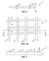
- Figure 1 shows a side sectional view of a known composite material 1 in use.
- the composite material 1 is supplied in sheets made up of drainage strips 10 positioned between textile layers 12.
- the textile layers 12 are permeable to water, whereas the drainage strips channel water along their length. In use the textile layers 12 are in contact with moist soil allowing water to pass into the drainage strips to be carried away from the soil.
- a problem arises when separate sheets of the composite material 1 are used to build up a drainage system over a large area.
- ends of the drainage strips forming a drainage outlet from a first material sheet must be carefully aligned with the ends of drainage strips forming a drainage inlet to a second material sheet. This may not be straightforward in cases where the sheets extend over large distances, are subject to crumpling between drainage strips and the drainage strips themselves are relatively narrow.
- separate drainage strips can not easily cooperate with one another to distribute drainage flow to other strips should any strip or strips become blocked.
- Example embodiments of the present invention aim to address at least one disadvantage of the prior art, whether identified herein or otherwise.
- the present invention provides a component for a composite material, the component comprising a sheet structure including a plurality of drainage members intersecting one another to provide fluid drainage paths that are mutually interconnected.
- the component is bounded by a drainage member along one edge thereof.
- the component is bounded by a drainage member along two edges thereof, preferably opposed edges.
- the component is bounded by a drainage member along each of its edges.
- fluid is to be understood as including any non-solid substance, for example liquids, gases, and combinations thereof.
- drainage includes drawing off of liquid, and venting of gases.
- the component comprises a sheet.
- the component comprises a roll of material.
- the component comprises one or more projections on a first side thereof comprising the fluid drainage paths there-between.
- the component comprises recessed portions providing the fluid drainage paths.
- the component comprises one or more projections on a second side thereof.
- the core comprises a random fibre core.
- the core comprises a net core.
- the fluid drainage paths are arranged to enable fluid to move through the core in three dimensions.
- the fluid drainage paths are arranged to enable fluid to move across the first side of the component in two non-parallel directions.
- the fluid drainage paths are arranged to provide a continuous fluid path through the composite material in a one direction, or in two non-parallel directions.
- the fluid drainage paths are arranged to enable fluid to move across the first side of the component from one end thereof to another.
- the fluid drainage paths are arranged to enable fluid to move across the first side of the component from one side thereof to another.
- the fluid drainage paths are arranged to enable fluid to move across the first side of the component from one end thereof to another and from one side thereof to another.
- the fluid drainage paths are all mutually interconnected.
- the component comprises a plurality of projections on one or both of first and second sides thereof.
- the projections are of substantially similar shape to each other.
- the projections are distributed in regular arrangement across the component.
- the drainage members in the plurality of drainage members intersect one another to provide fluid drainage paths that are mutually interconnected.
- the drainage members are formed of crossing strips of drainage material.
- the strips of drainage material are in fluid communication with one another at their intersections.
- the drainage members provide internal capacity for the fluid drainage paths.
- the drainage members comprise projections thereon and wherein the spaces between the projections define a plurality of interconnected fluid drainage paths that allow fluid to run across the first face of the component to thereby form the drainage members.
- the component comprises a plurality of openings between the drainage members.
- the or each opening in the component has a boundary comprising a drainage member.
- the or each opening in the component is surrounded by drainage members.
- the openings are arranged with a drainage member there-between.
- the drainage members comprise the fluid drainage paths thereon.
- the drainage members comprise the projections thereon.
- the openings and drainage members are arranged in a regular repeating pattern, preferably a grid or grid-like pattern.
- the drainage members comprise fluid drainage paths that form a first, micro drainage structure of the component, and the drainage members between openings in the component defines a macro drainage structure.
- the micro drainage structure is provided by fluid drainage paths within the drainage member material.
- the openings are generally rectangular in shape.
- the openings are generally square in shape.
- the openings are generally triangular in shape.
- the openings are generally oval in shape.
- the openings are generally circular in shape.
- the openings are of substantially similar shape to each other.
- the openings are distributed in regular arrangement across the component.
- the openings comprise more than 10% of the area of the component, preferably more than 20% of the area, more preferably more than 30%, preferably more than 40%, for example more than 50% of the area of the component.
- the openings comprise up to 90% of the area of the component, preferably up to 80%, more preferably up to 70%, preferably up to 60%, for example up to 55% of the area of the component. In especially preferred embodiments, the openings comprise approximately 50%-60% of the area of the component.
- the openings have a width dimension of greater than 25mm across the component, preferably greater than 50mm, more preferably greater than 100mm, even more preferably greater than 500mm, for example greater than 1000mm across the component.
- the openings have a length dimension of greater than 25mm across the component, preferably greater than 50mm, more preferably greater than 100mm, even more preferably greater than 500mm for example greater than 1000mm across the component.
- the drainage members material have dimensions of greater than 25mm, preferably greater than 50mm, more preferably greater than 75mm, for example 100mm separating openings on the component.
- the component is made of a fluid impermeable material, and/or has a fluid impermeable outermost layer.
- the component is made of a water impermeable material, and/or has a water impermeable outermost layer.
- the component may comprise a fluid permeable material, or comprise fluid permeable portions, for example to give in plane permeability.
- the fluid drainage paths are provided by fluid permeable portions of the component.
- the component comprises HDPE.
- the present invention provides a composite material, the material comprising a first component in combination with a second component, wherein the first component is that of the first aspect of the invention.
- the second component is a sheet.
- the second component is provided on a first side of the first component.
- the second component is fluid permeable.
- the second component is water permeable.
- the second component is gas permeable.
- the second component comprises a textile.
- the second component comprises a non-woven textile.
- the second component comprises a plastics material.
- the second component comprises a polypropylene material.
- the second component comprises a long staple fibre material.
- the second component comprises a needle punched material.
- the second component comprises a heat-treated material.
- the second component is fixedly coupled to the first component.
- the second component is fixedly coupled to the first component by adhesive, or by a thermal or other welding process.
- the second component is coupled to projections of the first component.
- the second component is coupled to projections of the first component such that fluid drainage paths are provided in the space between second component and a first side of the first component.
- the first and second components extend over the same area.
- the second component covers the entirety of the first component.
- the first component in use is generally incompressible in response to an applied working load.
- the second component is extensible from a rest position in which it lies above the first side of the component to an in use position in which it extends through the openings in the first component from a first side thereof to a second side thereof in response to an applied working load provided onto the second component from material pressed or pressing against the cover sheet.
- the composite material further comprises a third component.
- the third component is provided on a second side of the first component.
- the third component comprises some or all of the features described above in relation to the second component.
- the present invention provides a method of manufacturing a component for a composite material, the method comprising forming a sheet structure including a plurality of drainage members intersecting one another to provide mutually interconnected fluid drainage paths.
- the method comprises arranging a first drainage member across a second drainage member.
- the method comprises arranging a plurality of first drainage members across a plurality of second drainage members.
- the method comprises coupling the drainage members to one another, preferably at their intersections.
- the coupling comprises bonding, for example adhesive or heat welding.
- the method comprises interweaving a first drainage member with a plurality of second drainage members.
- the method comprises interweaving a first plurality of drainage members with a second plurality of drainage members.
- the drainage members in the first plurality are positioned generally parallel to one another.
- the drainage members in the second plurality are positioned generally parallel to one another.
- the each drainage member in the first plurality intersects each drainage member in the second plurality at a first predetermined intersection angle.
- the each drainage member in the second plurality intersects each drainage member in the first plurality at a second predetermined intersection angle.
- the first and/or second predetermined intersection angle is a right angle.
- the method comprises stamping out a region(s) of a component blank to form the component, with the drainage members remaining and leaving openings there-between.
- the present invention provides a method of manufacturing a composite material, the method comprising: manufacturing a first component for the material using the method of the third aspect of the present invention and coupling the first component to a second component.
- the coupling step comprises adhering or welding the first component to a second component.
- the present invention provides a method of manufacturing a composite material, the method comprising manufacturing a first component for the material as the component of the first aspect of the present invention and coupling the first component to a second component.
- the coupling step comprises adhering or welding the first component to a second component.
- the present invention provides a method of providing drainage using a the composite material of the second aspect of the present invention, or a composite material manufactured according to the third, fourth of fifth aspect of the present invention, the method comprising installing the composite material with the material to be drained such that the second component of the composite material is in contact with the material to be drained.
- a drainage structure including the composite material of the second aspect of the invention or a composite material manufactured according to the third, fourth of fifth aspect of the present invention.
- Figures 2-8 show parts of components 2 and components 2 for a composite material in accordance with an example embodiment of the present invention.
- the components 2 comprise a sheet structure including a plurality of drainage members 4 intersecting one another to provide fluid drainage paths that are mutually interconnected.
- the components 2 of Figures 2A-7B are formed of crossing strips of drainage material. Each strip of drainage material comprises a drainage member 4, and the drainage members 4 are in fluid communication with one another at their intersections.
- Figures 2A , and 3-7B show groups of parallel drainage members 4 intersecting one another at right angles, with elements of one group arranged to lie on elements of the other group, and be attached thereto.
- Figure 2B shows drainage members 4 that all lie substantially in one plane.
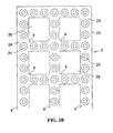
- Figures 8A and 8B show drainage members 4 that are interwoven with one another. Whereas the components 2 of Figures 2A and 3-8B comprise drainage members with internal capacity for providing fluid drainage paths, the component 2 of Figure 2B provides a plurality of projections 20 extending from a first face 21 thereof.
- the spaces on the first face 21 and the spaces between the projections 20 define a plurality of interconnected fluid drainage paths 24 that allow fluid to run across the first face 21 of the component 2, to thereby form the drainage members 4.
- the component 2 further comprises a plurality of openings 26 defined therein to allow communication between the first face 21 and a second, opposite face.
- the component 2 is useful in a composite material for providing fluid drainage, for example in underground applications such as landfill capping.
- the composite material may include a second component 6 in the form of a water permeable coversheet.
- the second component 6 covers the entirety of the first component 2.
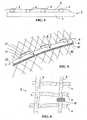
- Figure 5 shows a side sectional view of the composite material of first and second components 2, 6 in use in a drainage structure.
- a second face 22 of the first component 2 rests on a substantially impermeable membrane M, which itself lies on waste W.
- the second component 6 is fixed to the first face 21 of the core sheet 2 at the projections 20 and is in contact with moist soil S.
- the fluid drainage paths provided by the drainage members 4 are formed between the first face 21 of the first component 2 and the second component 6, and allow moisture from the soil S to run generally there-through within the first component 2 to facilitate drainage of moisture from the soil S.
- the weight of the soil S pressing on the second component 6 presses the second component down and through the openings in the first component 2 that fall between drainage members 4.
- the presence of space in the first component 2 does not have a significant adverse affect on the drainage capacity provided in typical installations.
- the first component includes a smaller amount of material and is hence lighter than an equivalent material without openings. In addition to weight saving, the use of a smaller amount of material can reduce manufacturing costs.
- the mutual interconnection between fluid drainage paths in intersecting drainage members 4 enables the first component 2 to be resilient to blockage of drainage members 4, and furthermore facilitates installation of drainage structures using the first component.
- Figure 6 shows a first component 2 in which a blockage B has prevented fluid flow along one fluid drainage path.
- the mutual interconnection of the blocked path with other intersecting mutually connected paths enables the drainage load to be shared by the remaining unblocked fluid flow paths, as shown by the dashed arrows indicating the direction of fluid flow.
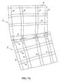
- Figures 7A and 7B show drainage structures in which adjacent first components 2 are in non-parallel alignment and with offset drainage members respectively.
- the fluid flowing out of the bottom edge of the higher one of the first components 2 is effectively collected into the fluid flow pathways of the lower one of the first components 2.
- the direction of fluid flow is generally indicated by the dashed arrows.
- the provision of drainage members that overlap one another contributes, as does the fact that the overlapping drainage members are generally at the edge of the first components 2.
- overlapping of intersecting drainage members 4 to provide secondary drainage paths that are not parallel to the primary drainage direction contributes to the effectiveness of the drainage structures described herein, and the ease of installation thereof.
- Figure 9 is a schematic flow diagram illustrating a method of manufacturing a first component 2 (steps S701 and S702) and of manufacturing a composite material (S703), according to example embodiments of the present invention.
- a plurality of intersecting drainage members with fluid flow pathways provided thereon or therein is arranged such that the fluid flow pathways are mutually interconnected.
- the second step S702 comprises coupling the drainage members to one another, for example by heat bonding.
- the first component may be formed by combining separate drainage members, e.g. by overlaying or weaving.
- first step S701 may comprise forming a sheet of material and the second step S702 may comprise forming openings therein to allow communication between the first face and the second face of the component.
- the second step S702 conveniently comprises stamping out the openings.
- the openings may be formed or resized by stretching.
- the first component manufactured in steps S701 and S702 is combined with a second component, and optionally a third component to form a composite material.
- the third step S703 comprises bonding the components by adhering and/or welding.
- the cover sheet comprises a fluid permeable layer
- Figure 8 is a schematic flow diagram of a method of providing drainage using a composite material according to an example embodiment of the present invention.
- the method comprises a first step S801 of installing a composite material as described herein on a substrate.
- the method further comprises the step S802 of placing material to be drained against the fluid permeable second component.
- the method may suitably further comprise providing a connection between the composite material and a further drainage structure to carry away fluid that enters into the composite material, for example by overlaying or butting up the composite material against a further sheet thereof.
- the components, composite materials and methods described herein are relatively cheap to produce and implement, offer easy installation, and address the problem of insufficient friction between components in the composite material and between a composite material and substrate.
- embodiments described herein are intended primarily for drainage of water from moist soil, other related embodiments can also be envisaged as suitable for draining other fluids, including gasses, from other media. Furthermore, the embodiments described may be combined with other components, for example by addition one or more further layers, according to particular engineering requirements. Equally, although the embodiments described herein comprise interconnections between all fluid drainage paths, embodiment of the present invention may provide some non-interconnected drainage paths, and some non-draining elements.
Description
- The present invention relates to composite materials and to components suitable for incorporation into composite materials. The present invention further relates to methods of manufacturing composite materials and components suitable for incorporation into composite materials. The present invention still further relates to methods of providing drainage using of the same, and to drainage structures including the same.
- In geotechnical engineering, man made composite materials are used in place of soil, clay, rock and the like to provide solutions to geotechnical engineering problems. Typical composite materials used in this field comprise two or more components such as textile sheets in combination with a grid, net or core. Typical applications for composite materials are provision of drainage and/or provision of moisture barrier around structures. A component for a composite material according to the preamble of claim 1 is known from
US 3795180 A . -
Figure 1 shows a side sectional view of a known composite material 1 in use. The composite material 1 is supplied in sheets made up ofdrainage strips 10 positioned betweentextile layers 12. Thetextile layers 12 are permeable to water, whereas the drainage strips channel water along their length. In use thetextile layers 12 are in contact with moist soil allowing water to pass into the drainage strips to be carried away from the soil. However, a problem arises when separate sheets of the composite material 1 are used to build up a drainage system over a large area. To enable efficient drainage, ends of the drainage strips forming a drainage outlet from a first material sheet must be carefully aligned with the ends of drainage strips forming a drainage inlet to a second material sheet. This may not be straightforward in cases where the sheets extend over large distances, are subject to crumpling between drainage strips and the drainage strips themselves are relatively narrow. Furthermore, separate drainage strips can not easily cooperate with one another to distribute drainage flow to other strips should any strip or strips become blocked. - Example embodiments of the present invention aim to address at least one disadvantage of the prior art, whether identified herein or otherwise.
- In a first aspect, the present invention provides a component for a composite material, the component comprising a sheet structure including a plurality of drainage members intersecting one another to provide fluid drainage paths that are mutually interconnected.
- Suitably, the component is bounded by a drainage member along one edge thereof. Suitably, the component is bounded by a drainage member along two edges thereof, preferably opposed edges. Suitably, the component is bounded by a drainage member along each of its edges.
- Herein, the term "fluid" is to be understood as including any non-solid substance, for example liquids, gases, and combinations thereof. Equally, the term "drainage" includes drawing off of liquid, and venting of gases.
- Suitably, the component comprises a sheet. Suitably, the component comprises a roll of material.
- Suitably, the component comprises one or more projections on a first side thereof comprising the fluid drainage paths there-between. Suitably, the component comprises recessed portions providing the fluid drainage paths. Suitably, the component comprises one or more projections on a second side thereof. Suitably, the core comprises a random fibre core. Suitably, the core comprises a net core. Suitably, the fluid drainage paths are arranged to enable fluid to move through the core in three dimensions. Suitably, the fluid drainage paths are arranged to enable fluid to move across the first side of the component in two non-parallel directions. Suitably, the fluid drainage paths are arranged to provide a continuous fluid path through the composite material in a one direction, or in two non-parallel directions. Suitably, the fluid drainage paths are arranged to enable fluid to move across the first side of the component from one end thereof to another. Suitably, the fluid drainage paths are arranged to enable fluid to move across the first side of the component from one side thereof to another. Suitably, the fluid drainage paths are arranged to enable fluid to move across the first side of the component from one end thereof to another and from one side thereof to another. Suitably, the fluid drainage paths are all mutually interconnected. Suitably the component comprises a plurality of projections on one or both of first and second sides thereof. Suitably, the projections are of substantially similar shape to each other. Suitably, the projections are distributed in regular arrangement across the component.
- Suitably, the drainage members in the plurality of drainage members intersect one another to provide fluid drainage paths that are mutually interconnected. Suitably, the drainage members are formed of crossing strips of drainage material. Suitably, the strips of drainage material are in fluid communication with one another at their intersections. Suitably, the drainage members provide internal capacity for the fluid drainage paths. Suitably, the drainage members comprise projections thereon and wherein the spaces between the projections define a plurality of interconnected fluid drainage paths that allow fluid to run across the first face of the component to thereby form the drainage members.
- Suitably, the component comprises a plurality of openings between the drainage members.
- Suitably, the or each opening in the component has a boundary comprising a drainage member. Suitably, the or each opening in the component is surrounded by drainage members. Suitably, the openings are arranged with a drainage member there-between. Suitably, the drainage members comprise the fluid drainage paths thereon. Suitably, the drainage members comprise the projections thereon. Suitably, the openings and drainage members are arranged in a regular repeating pattern, preferably a grid or grid-like pattern. Suitably, the drainage members comprise fluid drainage paths that form a first, micro drainage structure of the component, and the drainage members between openings in the component defines a macro drainage structure. Suitably, the micro drainage structure is provided by fluid drainage paths within the drainage member material.
- Suitably, the openings are generally rectangular in shape. Suitably, the openings are generally square in shape. Suitably, the openings are generally triangular in shape. Suitably the openings are generally oval in shape. Suitably, the openings are generally circular in shape. Suitably, the openings are of substantially similar shape to each other. Suitably, the openings are distributed in regular arrangement across the component.
- Suitably, the openings comprise more than 10% of the area of the component, preferably more than 20% of the area, more preferably more than 30%, preferably more than 40%, for example more than 50% of the area of the component. Suitably, the openings comprise up to 90% of the area of the component, preferably up to 80%, more preferably up to 70%, preferably up to 60%, for example up to 55% of the area of the component. In especially preferred embodiments, the openings comprise approximately 50%-60% of the area of the component.
- Suitably, the openings have a width dimension of greater than 25mm across the component, preferably greater than 50mm, more preferably greater than 100mm, even more preferably greater than 500mm, for example greater than 1000mm across the component. Suitably, the openings have a length dimension of greater than 25mm across the component, preferably greater than 50mm, more preferably greater than 100mm, even more preferably greater than 500mm for example greater than 1000mm across the component.
- Suitably, the drainage members material have dimensions of greater than 25mm, preferably greater than 50mm, more preferably greater than 75mm, for example 100mm separating openings on the component.
- Suitably, the component is made of a fluid impermeable material, and/or has a fluid impermeable outermost layer. Suitably, the component is made of a water impermeable material, and/or has a water impermeable outermost layer. In alternative embodiments the component may comprise a fluid permeable material, or comprise fluid permeable portions, for example to give in plane permeability. Suitably, the fluid drainage paths are provided by fluid permeable portions of the component.
- Suitably, the component comprises HDPE.
- In a second aspect, the present invention provides a composite material, the material comprising a first component in combination with a second component, wherein the first component is that of the first aspect of the invention.
- Suitably, the second component is a sheet. Suitably, the second component is provided on a first side of the first component.
- Suitably, the second component is fluid permeable. Suitably, the second component is water permeable. Suitably, the second component is gas permeable. Suitably, the second component comprises a textile. Suitably, the second component comprises a non-woven textile. Suitably, the second component comprises a plastics material. Suitably, the second component comprises a polypropylene material. Suitably, the second component comprises a long staple fibre material. Suitably, the second component comprises a needle punched material. Suitably, the second component comprises a heat-treated material.
- Suitably, the second component is fixedly coupled to the first component. Suitably, the second component is fixedly coupled to the first component by adhesive, or by a thermal or other welding process.
- Suitably, the second component is coupled to projections of the first component. Suitably, the second component is coupled to projections of the first component such that fluid drainage paths are provided in the space between second component and a first side of the first component.
- Suitably, the first and second components extend over the same area. Suitably, the second component covers the entirety of the first component.
- Suitably, in use the first component is generally incompressible in response to an applied working load. Suitably, the second component is extensible from a rest position in which it lies above the first side of the component to an in use position in which it extends through the openings in the first component from a first side thereof to a second side thereof in response to an applied working load provided onto the second component from material pressed or pressing against the cover sheet.
- Suitably, the composite material further comprises a third component. Suitably, the third component is provided on a second side of the first component. Suitably, the third component comprises some or all of the features described above in relation to the second component.
- In a third aspect, the present invention provides a method of manufacturing a component for a composite material, the method comprising forming a sheet structure including a plurality of drainage members intersecting one another to provide mutually interconnected fluid drainage paths.
- Suitably, the method comprises arranging a first drainage member across a second drainage member. Suitably, the method comprises arranging a plurality of first drainage members across a plurality of second drainage members. Suitably, the method comprises coupling the drainage members to one another, preferably at their intersections. Suitably, the coupling comprises bonding, for example adhesive or heat welding.
- Suitably, the method comprises interweaving a first drainage member with a plurality of second drainage members. Suitably, the method comprises interweaving a first plurality of drainage members with a second plurality of drainage members. Suitably, the drainage members in the first plurality are positioned generally parallel to one another. Suitably, the drainage members in the second plurality are positioned generally parallel to one another. Suitably, the each drainage member in the first plurality intersects each drainage member in the second plurality at a first predetermined intersection angle. Suitably, the each drainage member in the second plurality intersects each drainage member in the first plurality at a second predetermined intersection angle. Suitably, the first and/or second predetermined intersection angle is a right angle.
- Suitably, the method comprises stamping out a region(s) of a component blank to form the component, with the drainage members remaining and leaving openings there-between.
- In a fourth aspect, the present invention provides a method of manufacturing a composite material, the method comprising: manufacturing a first component for the material using the method of the third aspect of the present invention and coupling the first component to a second component.
- Suitably, the coupling step comprises adhering or welding the first component to a second component.
- In a fifth aspect, the present invention provides a method of manufacturing a composite material, the method comprising manufacturing a first component for the material as the component of the first aspect of the present invention and coupling the first component to a second component.
- Suitably, the coupling step comprises adhering or welding the first component to a second component.
- In a sixth aspect the present invention provides a method of providing drainage using a the composite material of the second aspect of the present invention, or a composite material manufactured according to the third, fourth of fifth aspect of the present invention, the method comprising installing the composite material with the material to be drained such that the second component of the composite material is in contact with the material to be drained.
- In a seventh aspect of the present invention there is provided a drainage structure including the composite material of the second aspect of the invention or a composite material manufactured according to the third, fourth of fifth aspect of the present invention.
- For a better understanding of the invention, and to show how embodiments of the same may be carried into effect, reference will now be made, by way of example, to the accompanying diagrammatic drawings in which:
-
Figure 1 shows a side sectional view of a known composite material in use; -
Figures 2A and2B show plan views of portions of components for a composite material, each in accordance with an example embodiment of the present invention; -
Figure 3 shows a sectional view along line A-A ofFigure 2A , looking in the direction of the arrows; -
Figure 4 shows an end view the component ofFigure 2A in combination with a second component to provide a composite material in accordance with an example embodiment of the present invention; -
Figure 5 is a side sectional view of the component ofFigure 2A in use in a drainage structure according to an example embodiment of the present invention; -
Figure 6 is a schematic plan view showing blockage of one drainage member and diverted flow in a component in accordance with an example embodiment of the invention; -
Figures 7A and7B are schematic plan views of overlapping composite material sheets according to example embodiments of the present invention at the edges thereof to enable flow from one sheet into the next; -
Figures 8A and 8B are schematic plans views of other patterns of drainage members useful in alternative embodiments of the present invention; -
Figure 9 is a schematic flow diagram illustrating a method of manufacturing a component for a composite material and of manufacturing a composite material according to example embodiments of the present invention; and -
Figure 10 is a schematic flow diagram of a method of providing drainage using a composite material according to an example embodiment of the present invention. -
Figures 2-8 show parts ofcomponents 2 andcomponents 2 for a composite material in accordance with an example embodiment of the present invention. Thecomponents 2 comprise a sheet structure including a plurality ofdrainage members 4 intersecting one another to provide fluid drainage paths that are mutually interconnected. - The
components 2 ofFigures 2A-7B are formed of crossing strips of drainage material. Each strip of drainage material comprises adrainage member 4, and thedrainage members 4 are in fluid communication with one another at their intersections.Figures 2A , and3-7B show groups ofparallel drainage members 4 intersecting one another at right angles, with elements of one group arranged to lie on elements of the other group, and be attached thereto.Figure 2B showsdrainage members 4 that all lie substantially in one plane.Figures 8A and 8B showdrainage members 4 that are interwoven with one another. Whereas thecomponents 2 ofFigures 2A and3-8B comprise drainage members with internal capacity for providing fluid drainage paths, thecomponent 2 ofFigure 2B provides a plurality ofprojections 20 extending from afirst face 21 thereof. The spaces on thefirst face 21 and the spaces between theprojections 20 define a plurality of interconnectedfluid drainage paths 24 that allow fluid to run across thefirst face 21 of thecomponent 2, to thereby form thedrainage members 4. Thecomponent 2 further comprises a plurality ofopenings 26 defined therein to allow communication between thefirst face 21 and a second, opposite face. - The
component 2 is useful in a composite material for providing fluid drainage, for example in underground applications such as landfill capping. As shown inFigure 4 and 5 the composite material may include asecond component 6 in the form of a water permeable coversheet. Thesecond component 6 covers the entirety of thefirst component 2. -
Figure 5 shows a side sectional view of the composite material of first andsecond components second face 22 of thefirst component 2 rests on a substantially impermeable membrane M, which itself lies on waste W. Thesecond component 6 is fixed to thefirst face 21 of thecore sheet 2 at theprojections 20 and is in contact with moist soil S. The fluid drainage paths provided by thedrainage members 4 are formed between thefirst face 21 of thefirst component 2 and thesecond component 6, and allow moisture from the soil S to run generally there-through within thefirst component 2 to facilitate drainage of moisture from the soil S. The weight of the soil S pressing on thesecond component 6 presses the second component down and through the openings in thefirst component 2 that fall betweendrainage members 4. - In this way the relatively high frictional resistance to sliding of the
second component 6 over the substantially impermeable membrane M is achieved, while maintaining good drainage performance using thedrainage members 4 offirst component 2. In embodiments where there is no fixed coupling between thefirst component 2 and thesecond component 6, again frictional engagement there-between to resist shearing forces is enhanced by the effect of thesecond component 6 pressing on thedrainage members 4, e.g. the edges thereof. There are a number of factors in determining the degree to which thesecond component 6 extends into and through any openings betweendrainage members 4, including one or more of: the loading applied to thesecond component 6, the depth of thefirst component 2, the size and shape of any projections on thefirst component 2, the size of the openings, and the material properties of thesecond component 6. It will be appreciated that embodiments of the present invention provide to suitable combinations of these factors to work effectively in typical underground drainage situations where shearing loads may be a design consideration. - Surprisingly, the presence of space in the
first component 2 does not have a significant adverse affect on the drainage capacity provided in typical installations. However, the first component includes a smaller amount of material and is hence lighter than an equivalent material without openings. In addition to weight saving, the use of a smaller amount of material can reduce manufacturing costs. - Furthermore, the mutual interconnection between fluid drainage paths in intersecting
drainage members 4 enables thefirst component 2 to be resilient to blockage ofdrainage members 4, and furthermore facilitates installation of drainage structures using the first component. -
Figure 6 shows afirst component 2 in which a blockage B has prevented fluid flow along one fluid drainage path. The mutual interconnection of the blocked path with other intersecting mutually connected paths enables the drainage load to be shared by the remaining unblocked fluid flow paths, as shown by the dashed arrows indicating the direction of fluid flow. -
Figures 7A and7B show drainage structures in which adjacentfirst components 2 are in non-parallel alignment and with offset drainage members respectively. In both cases, the fluid flowing out of the bottom edge of the higher one of thefirst components 2 is effectively collected into the fluid flow pathways of the lower one of thefirst components 2. The direction of fluid flow is generally indicated by the dashed arrows. The provision of drainage members that overlap one another contributes, as does the fact that the overlapping drainage members are generally at the edge of thefirst components 2. In general, overlapping of intersectingdrainage members 4 to provide secondary drainage paths that are not parallel to the primary drainage direction contributes to the effectiveness of the drainage structures described herein, and the ease of installation thereof. -
Figure 9 is a schematic flow diagram illustrating a method of manufacturing a first component 2 (steps S701 and S702) and of manufacturing a composite material (S703), according to example embodiments of the present invention. - At step S701 a plurality of intersecting drainage members with fluid flow pathways provided thereon or therein is arranged such that the fluid flow pathways are mutually interconnected. The second step S702 comprises coupling the drainage members to one another, for example by heat bonding. In alternative methods of manufacturing, the first component may be formed by combining separate drainage members, e.g. by overlaying or weaving.
- In an alternative embodiment the first step S701 may comprise forming a sheet of material and the second step S702 may comprise forming openings therein to allow communication between the first face and the second face of the component. In such embodiments the second step S702 conveniently comprises stamping out the openings. In yet another alternative method of manufacturing, the openings may be formed or resized by stretching.
- At the third step the first component manufactured in steps S701 and S702 is combined with a second component, and optionally a third component to form a composite material. The third step S703 comprises bonding the components by adhering and/or welding. The cover sheet comprises a fluid permeable layer
-
Figure 8 is a schematic flow diagram of a method of providing drainage using a composite material according to an example embodiment of the present invention. The method comprises a first step S801 of installing a composite material as described herein on a substrate. The method further comprises the step S802 of placing material to be drained against the fluid permeable second component. The method may suitably further comprise providing a connection between the composite material and a further drainage structure to carry away fluid that enters into the composite material, for example by overlaying or butting up the composite material against a further sheet thereof. - The components, composite materials and methods described herein are relatively cheap to produce and implement, offer easy installation, and address the problem of insufficient friction between components in the composite material and between a composite material and substrate.
- Although the embodiments described herein are intended primarily for drainage of water from moist soil, other related embodiments can also be envisaged as suitable for draining other fluids, including gasses, from other media. Furthermore, the embodiments described may be combined with other components, for example by addition one or more further layers, according to particular engineering requirements. Equally, although the embodiments described herein comprise interconnections between all fluid drainage paths, embodiment of the present invention may provide some non-interconnected drainage paths, and some non-draining elements.
- Attention is directed to all papers and documents which are filed concurrently with or previous to this specification in connection with this application and which are open to public inspection with this specification, and the contents of all such papers and documents are incorporated herein by reference.
- All of the features disclosed in this specification (including any accompanying claims, abstract and drawings), and/or all of the steps of any method or process so disclosed, may be combined in any combination, except combinations where at least some of such features and/or steps are mutually exclusive.
- Each feature disclosed in this specification (including any accompanying claims, abstract and drawings) may be replaced by alternative features serving the same, equivalent or similar purpose, unless expressly stated otherwise. Thus, unless expressly stated otherwise, each feature disclosed is one example only of a generic series of equivalent or similar features.
- The invention is not restricted to the details of the foregoing embodiment(s). The invention extends to any novel one, or any novel combination, of the features disclosed in this specification (including any accompanying claims, abstract and drawings), or to any novel one, or any novel combination, of the steps of any method or process so disclosed.
Claims (15)
- A component for a composite material, the component comprising a sheet structure including a plurality of drainage members intersecting one another to provide fluid drainage paths that are mutually interconnected, characterised in that the mutually interconnected drainage paths are provided in the intersecting drainage members.
- The component of claim 1, bounded by a drainage member along each of its edges.
- The component of claim 1 or 2, wherein the fluid drainage paths are arranged to provide a continuous fluid path through the composite material in two non-parallel directions.
- The component of any preceding claim, wherein the drainage members are formed of crossing strips of drainage material.
- The component of claim 4, wherein the strips of drainage material are in fluid communication with one another at their intersections.
- The component of any preceding claim, wherein the component comprises a plurality of openings between the drainage members, and the or each opening in the component has a boundary comprising a drainage member.
- The component of claim 6, wherein the openings comprise more than 10% of the area of the component, preferably more than 20% of the area, more preferably more than 30%, preferably more than 40%, for example more than 50% of the area of the component.
- A composite material, the material comprising a first component in combination with a second component, wherein the first component is that of any one of claims 1-7, wherein in use the first component is generally incompressible in response to an applied working load and the second component is extensible from a rest position in which it lies above the first side of the component to an in use position in which it extends through openings in the first component from a first side thereof to a second side thereof in response to an applied working load provided onto the second component from material pressed or pressing against the cover sheet.
- A method of manufacturing a component for a composite material, the method comprising forming a sheet structure including a plurality of drainage members intersecting one another to provide mutually interconnected fluid drainage paths in the intersecting drainage members.
- The method of claim 9, comprising arranging a plurality of first drainage members across a plurality of second drainage members.
- The method of claim 9 or 10, comprising coupling the drainage members to one another, preferably at their intersections.
- The method of any one of claims 9 to 11, comprising interweaving a first drainage member with a plurality of second drainage members or interweaving a first plurality of drainage members with a second plurality of drainage members.
- The method of claim 9 comprises stamping out one or more regions of a component blank to form the component, with the drainage members remaining and leaving openings there-between.
- A method of providing drainage using a the composite material of claim8, the method comprising installing the composite material with the material to be drained such that the second component of the composite material is in contact with the material to be drained.
- A drainage structure including the composite material of claim8.
Applications Claiming Priority (2)
| Application Number | Priority Date | Filing Date | Title |
|---|---|---|---|
| GB1015290.8A GB2483649A (en) | 2010-09-14 | 2010-09-14 | Drainage component for use in Composite Material |
| PCT/GB2011/051731 WO2012035347A2 (en) | 2010-09-14 | 2011-09-14 | Composite material, component suitable for use in composite material and related methods and structures |
Publications (2)
| Publication Number | Publication Date |
|---|---|
| EP2616592A2 EP2616592A2 (en) | 2013-07-24 |
| EP2616592B1 true EP2616592B1 (en) | 2014-06-11 |
Family
ID=43065150
Family Applications (1)
| Application Number | Title | Priority Date | Filing Date |
|---|---|---|---|
| EP20110776821 Active EP2616592B1 (en) | 2010-09-14 | 2011-09-14 | Composite material, component suitable for use in composite material and related methods and structures |
Country Status (8)
| Country | Link |
|---|---|
| US (1) | US10054268B2 (en) |
| EP (1) | EP2616592B1 (en) |
| CN (1) | CN103189570B (en) |
| AU (1) | AU2011303611B2 (en) |
| ES (1) | ES2502469T3 (en) |
| GB (1) | GB2483649A (en) |
| WO (1) | WO2012035347A2 (en) |
| ZA (1) | ZA201302660B (en) |
Family Cites Families (21)
| Publication number | Priority date | Publication date | Assignee | Title |
|---|---|---|---|---|
| GB214149A (en) | 1923-08-01 | 1924-04-17 | Claude Clench | Improvements in apparatus for indicating the level of liquid in boilers, tanks or other receptacles |
| US3795180A (en) * | 1969-02-26 | 1974-03-05 | Conwed Corp | Plastic net deck surface and drainage unit |
| FR2441685B1 (en) | 1978-11-14 | 1985-12-13 | Vignon Jean Francois | ALVEOLAR TEXTILE MATERIAL FOR CONSOLIDATING AND SANITIZING FLOORS FOR PUBLIC OR OTHER WORKS |
| CA1229993A (en) * | 1982-07-28 | 1987-12-08 | Grace (W.R.) & Co. | Construction barrier board |
| DE3313476A1 (en) * | 1983-04-14 | 1984-10-18 | Werner 5860 Iserlohn Schlüter | FILM-LIKE PLASTIC PLATE FOR DRAINAGE IN THE CONSTRUCTION OF SCREED OR TILE COVERED FLOORS, TERRACES, BALCONIES OD. DGL. |
| GB8611941D0 (en) * | 1986-05-16 | 1986-06-25 | Schlegel Uk Holdings | Protection membrane |
| AU6853387A (en) * | 1986-09-05 | 1988-03-10 | Leucadia, Inc. | Subsurface drainage matting |
| US5401552A (en) * | 1994-01-28 | 1995-03-28 | Slt Environmental, Inc. | Geocomposite liner |
| US5567077A (en) * | 1994-02-17 | 1996-10-22 | Yang; Jesse S. | Drainage network |
| US7131788B2 (en) * | 2000-02-10 | 2006-11-07 | Advanced Geotech Systems | High-flow void-maintaining membrane laminates, grids and methods |
| CN2541517Y (en) | 2002-03-05 | 2003-03-26 | 李兰英 | Net block drainage board |
| DE102004026652B4 (en) * | 2003-11-06 | 2023-04-20 | Blanke Gmbh & Co.Kg, | Multi-layer decoupling and sealing system |
| US7108454B2 (en) * | 2004-10-12 | 2006-09-19 | Airfield Systems, L.L.C. | Subsurface drainage system and drain structure therefor |
| WO2007100256A1 (en) * | 2006-03-01 | 2007-09-07 | Oldroyd Systemer As | Profiled watertight building sheet and method for production of same |
| ITMI20060498A1 (en) | 2006-03-20 | 2007-09-21 | Tenax Spa | MULTILAYERED NET FOR DRAINAGE OF FLUIDS PARTICULARLY FOR GEOTECHNICAL USE |
| CN201003168Y (en) | 2006-11-27 | 2008-01-09 | 北京市市政工程设计研究总院 | Quick drainage pipe guide layer water diversion structure for garbage landfill field |
| KR20090023769A (en) * | 2007-09-03 | 2009-03-06 | 주식회사 골든포우 | Geo-synthetic water blocking materials |
| CN101487236B (en) | 2008-01-18 | 2011-12-28 | 单炜 | Seepage and drainage geogrid |
| GB2462994B (en) * | 2008-08-27 | 2013-01-23 | Geofabrics Ltd | Composite material for use as a liner |
| CN201357004Y (en) | 2009-02-18 | 2009-12-09 | 南通华新环保设备工程有限公司 | Filter plate |
| CN101644058B (en) | 2009-09-09 | 2011-03-16 | 合肥工业大学 | Side slope safety and ecological shelter components |
-
2010
- 2010-09-14 GB GB1015290.8A patent/GB2483649A/en not_active Withdrawn
-
2011
- 2011-09-14 CN CN201180051488.5A patent/CN103189570B/en active Active
- 2011-09-14 ES ES11776821.8T patent/ES2502469T3/en active Active
- 2011-09-14 AU AU2011303611A patent/AU2011303611B2/en active Active
- 2011-09-14 US US13/823,284 patent/US10054268B2/en active Active
- 2011-09-14 EP EP20110776821 patent/EP2616592B1/en active Active
- 2011-09-14 WO PCT/GB2011/051731 patent/WO2012035347A2/en active Application Filing
-
2013
- 2013-04-12 ZA ZA2013/02660A patent/ZA201302660B/en unknown
Also Published As
| Publication number | Publication date |
|---|---|
| US10054268B2 (en) | 2018-08-21 |
| CN103189570B (en) | 2016-11-09 |
| AU2011303611A1 (en) | 2013-05-02 |
| GB201015290D0 (en) | 2010-10-27 |
| CN103189570A (en) | 2013-07-03 |
| ZA201302660B (en) | 2014-06-25 |
| GB2483649A (en) | 2012-03-21 |
| ES2502469T3 (en) | 2014-10-03 |
| AU2011303611B2 (en) | 2017-01-12 |
| EP2616592A2 (en) | 2013-07-24 |
| US20130167942A1 (en) | 2013-07-04 |
| WO2012035347A3 (en) | 2012-09-27 |
| WO2012035347A2 (en) | 2012-03-22 |
Similar Documents
| Publication | Publication Date | Title |
|---|---|---|
| EP1226315B1 (en) | Modular drainage channels | |
| US4639165A (en) | Drainage tube | |
| US8440289B2 (en) | Composite for geotechnics, building and the like, with impermeable layer | |
| US6241421B1 (en) | Subterranean drain assembly | |
| US5258217A (en) | Landfill liner | |
| ES2678200T3 (en) | Geosynthetic compound for filtration and drainage of fine grain geomaterials and method of manufacturing it | |
| WO2001053608A1 (en) | Structural modular interconnectable subsoil drainage cell | |
| WO2013173426A1 (en) | Self-anchoring turf reinforcement mat and reusable sediment filtration mat | |
| EP2616592B1 (en) | Composite material, component suitable for use in composite material and related methods and structures | |
| EP2616593B1 (en) | Composite material | |
| JP6573505B2 (en) | Construction cell structure and construction method | |
| JP2006037470A (en) | Drain plate | |
| EP2909385B1 (en) | Subterranean drainage structure and base unit therefor | |
| JP6692135B2 (en) | Construction cell structure and construction method | |
| JP3532464B2 (en) | Construction method of horizontal drain | |
| EP2383392A1 (en) | Drain system | |
| EP0499442A2 (en) | Underground drainage | |
| EP2246476A1 (en) | Drain system, as well as sleeve for such drain system | |
| JP4874224B2 (en) | Drain material and ground improvement device | |
| KR20090011499U (en) | A drainage seat using non-woven fabric having water way | |
| JPH0612524U (en) | Drain material | |
| JPH04131418A (en) | Drainage member in civil engineering work and drainage works in ground | |
| CS249821B1 (en) | Filtering drain geotextiles |
Legal Events
| Date | Code | Title | Description |
|---|---|---|---|
| PUAI | Public reference made under article 153(3) epc to a published international application that has entered the european phase |
Free format text: ORIGINAL CODE: 0009012 |
|
| 17P | Request for examination filed |
Effective date: 20130412 |
|
| AK | Designated contracting states |
Kind code of ref document: A2 Designated state(s): AL AT BE BG CH CY CZ DE DK EE ES FI FR GB GR HR HU IE IS IT LI LT LU LV MC MK MT NL NO PL PT RO RS SE SI SK SM TR |
|
| DAX | Request for extension of the european patent (deleted) | ||
| GRAP | Despatch of communication of intention to grant a patent |
Free format text: ORIGINAL CODE: EPIDOSNIGR1 |
|
| INTG | Intention to grant announced |
Effective date: 20140219 |
|
| GRAS | Grant fee paid |
Free format text: ORIGINAL CODE: EPIDOSNIGR3 |
|
| GRAA | (expected) grant |
Free format text: ORIGINAL CODE: 0009210 |
|
| AK | Designated contracting states |
Kind code of ref document: B1 Designated state(s): AL AT BE BG CH CY CZ DE DK EE ES FI FR GB GR HR HU IE IS IT LI LT LU LV MC MK MT NL NO PL PT RO RS SE SI SK SM TR |
|
| REG | Reference to a national code |
Ref country code: GB Ref legal event code: FG4D |
|
| REG | Reference to a national code |
Ref country code: CH Ref legal event code: EP |
|
| REG | Reference to a national code |
Ref country code: IE Ref legal event code: FG4D |
|
| REG | Reference to a national code |
Ref country code: AT Ref legal event code: REF Ref document number: 672334 Country of ref document: AT Kind code of ref document: T Effective date: 20140715 |
|
| REG | Reference to a national code |
Ref country code: DE Ref legal event code: R096 Ref document number: 602011007672 Country of ref document: DE Effective date: 20140724 |
|
| REG | Reference to a national code |
Ref country code: ES Ref legal event code: FG2A Ref document number: 2502469 Country of ref document: ES Kind code of ref document: T3 Effective date: 20141003 |
|
| REG | Reference to a national code |
Ref country code: NL Ref legal event code: T3 |
|
| PG25 | Lapsed in a contracting state [announced via postgrant information from national office to epo] |
Ref country code: LT Free format text: LAPSE BECAUSE OF FAILURE TO SUBMIT A TRANSLATION OF THE DESCRIPTION OR TO PAY THE FEE WITHIN THE PRESCRIBED TIME-LIMIT Effective date: 20140611 Ref country code: FI Free format text: LAPSE BECAUSE OF FAILURE TO SUBMIT A TRANSLATION OF THE DESCRIPTION OR TO PAY THE FEE WITHIN THE PRESCRIBED TIME-LIMIT Effective date: 20140611 Ref country code: GR Free format text: LAPSE BECAUSE OF FAILURE TO SUBMIT A TRANSLATION OF THE DESCRIPTION OR TO PAY THE FEE WITHIN THE PRESCRIBED TIME-LIMIT Effective date: 20140912 Ref country code: NO Free format text: LAPSE BECAUSE OF FAILURE TO SUBMIT A TRANSLATION OF THE DESCRIPTION OR TO PAY THE FEE WITHIN THE PRESCRIBED TIME-LIMIT Effective date: 20140911 |
|
| REG | Reference to a national code |
Ref country code: AT Ref legal event code: MK05 Ref document number: 672334 Country of ref document: AT Kind code of ref document: T Effective date: 20140611 |
|
| REG | Reference to a national code |
Ref country code: LT Ref legal event code: MG4D |
|
| PG25 | Lapsed in a contracting state [announced via postgrant information from national office to epo] |
Ref country code: HR Free format text: LAPSE BECAUSE OF FAILURE TO SUBMIT A TRANSLATION OF THE DESCRIPTION OR TO PAY THE FEE WITHIN THE PRESCRIBED TIME-LIMIT Effective date: 20140611 Ref country code: SE Free format text: LAPSE BECAUSE OF FAILURE TO SUBMIT A TRANSLATION OF THE DESCRIPTION OR TO PAY THE FEE WITHIN THE PRESCRIBED TIME-LIMIT Effective date: 20140611 Ref country code: RS Free format text: LAPSE BECAUSE OF FAILURE TO SUBMIT A TRANSLATION OF THE DESCRIPTION OR TO PAY THE FEE WITHIN THE PRESCRIBED TIME-LIMIT Effective date: 20140611 Ref country code: LV Free format text: LAPSE BECAUSE OF FAILURE TO SUBMIT A TRANSLATION OF THE DESCRIPTION OR TO PAY THE FEE WITHIN THE PRESCRIBED TIME-LIMIT Effective date: 20140611 |
|
| PG25 | Lapsed in a contracting state [announced via postgrant information from national office to epo] |
Ref country code: PT Free format text: LAPSE BECAUSE OF FAILURE TO SUBMIT A TRANSLATION OF THE DESCRIPTION OR TO PAY THE FEE WITHIN THE PRESCRIBED TIME-LIMIT Effective date: 20141013 Ref country code: RO Free format text: LAPSE BECAUSE OF FAILURE TO SUBMIT A TRANSLATION OF THE DESCRIPTION OR TO PAY THE FEE WITHIN THE PRESCRIBED TIME-LIMIT Effective date: 20140611 Ref country code: CZ Free format text: LAPSE BECAUSE OF FAILURE TO SUBMIT A TRANSLATION OF THE DESCRIPTION OR TO PAY THE FEE WITHIN THE PRESCRIBED TIME-LIMIT Effective date: 20140611 Ref country code: EE Free format text: LAPSE BECAUSE OF FAILURE TO SUBMIT A TRANSLATION OF THE DESCRIPTION OR TO PAY THE FEE WITHIN THE PRESCRIBED TIME-LIMIT Effective date: 20140611 Ref country code: SK Free format text: LAPSE BECAUSE OF FAILURE TO SUBMIT A TRANSLATION OF THE DESCRIPTION OR TO PAY THE FEE WITHIN THE PRESCRIBED TIME-LIMIT Effective date: 20140611 |
|
| PG25 | Lapsed in a contracting state [announced via postgrant information from national office to epo] |
Ref country code: AT Free format text: LAPSE BECAUSE OF FAILURE TO SUBMIT A TRANSLATION OF THE DESCRIPTION OR TO PAY THE FEE WITHIN THE PRESCRIBED TIME-LIMIT Effective date: 20140611 Ref country code: IS Free format text: LAPSE BECAUSE OF FAILURE TO SUBMIT A TRANSLATION OF THE DESCRIPTION OR TO PAY THE FEE WITHIN THE PRESCRIBED TIME-LIMIT Effective date: 20141011 Ref country code: PL Free format text: LAPSE BECAUSE OF FAILURE TO SUBMIT A TRANSLATION OF THE DESCRIPTION OR TO PAY THE FEE WITHIN THE PRESCRIBED TIME-LIMIT Effective date: 20140611 |
|
| REG | Reference to a national code |
Ref country code: DE Ref legal event code: R097 Ref document number: 602011007672 Country of ref document: DE |
|
| PLBE | No opposition filed within time limit |
Free format text: ORIGINAL CODE: 0009261 |
|
| STAA | Information on the status of an ep patent application or granted ep patent |
Free format text: STATUS: NO OPPOSITION FILED WITHIN TIME LIMIT |
|
| PG25 | Lapsed in a contracting state [announced via postgrant information from national office to epo] |
Ref country code: LU Free format text: LAPSE BECAUSE OF FAILURE TO SUBMIT A TRANSLATION OF THE DESCRIPTION OR TO PAY THE FEE WITHIN THE PRESCRIBED TIME-LIMIT Effective date: 20140914 Ref country code: MC Free format text: LAPSE BECAUSE OF FAILURE TO SUBMIT A TRANSLATION OF THE DESCRIPTION OR TO PAY THE FEE WITHIN THE PRESCRIBED TIME-LIMIT Effective date: 20140611 Ref country code: DK Free format text: LAPSE BECAUSE OF FAILURE TO SUBMIT A TRANSLATION OF THE DESCRIPTION OR TO PAY THE FEE WITHIN THE PRESCRIBED TIME-LIMIT Effective date: 20140611 |
|
| REG | Reference to a national code |
Ref country code: CH Ref legal event code: PL |
|
| 26N | No opposition filed |
Effective date: 20150312 |
|
| REG | Reference to a national code |
Ref country code: DE Ref legal event code: R097 Ref document number: 602011007672 Country of ref document: DE Effective date: 20150312 |
|
| PG25 | Lapsed in a contracting state [announced via postgrant information from national office to epo] |
Ref country code: CH Free format text: LAPSE BECAUSE OF NON-PAYMENT OF DUE FEES Effective date: 20140930 Ref country code: SI Free format text: LAPSE BECAUSE OF FAILURE TO SUBMIT A TRANSLATION OF THE DESCRIPTION OR TO PAY THE FEE WITHIN THE PRESCRIBED TIME-LIMIT Effective date: 20140611 Ref country code: LI Free format text: LAPSE BECAUSE OF NON-PAYMENT OF DUE FEES Effective date: 20140930 |
|
| REG | Reference to a national code |
Ref country code: FR Ref legal event code: PLFP Year of fee payment: 5 |
|
| PG25 | Lapsed in a contracting state [announced via postgrant information from national office to epo] |
Ref country code: SM Free format text: LAPSE BECAUSE OF FAILURE TO SUBMIT A TRANSLATION OF THE DESCRIPTION OR TO PAY THE FEE WITHIN THE PRESCRIBED TIME-LIMIT Effective date: 20140611 |
|
| PG25 | Lapsed in a contracting state [announced via postgrant information from national office to epo] |
Ref country code: CY Free format text: LAPSE BECAUSE OF FAILURE TO SUBMIT A TRANSLATION OF THE DESCRIPTION OR TO PAY THE FEE WITHIN THE PRESCRIBED TIME-LIMIT Effective date: 20140611 Ref country code: MT Free format text: LAPSE BECAUSE OF FAILURE TO SUBMIT A TRANSLATION OF THE DESCRIPTION OR TO PAY THE FEE WITHIN THE PRESCRIBED TIME-LIMIT Effective date: 20140611 |
|
| PG25 | Lapsed in a contracting state [announced via postgrant information from national office to epo] |
Ref country code: HU Free format text: LAPSE BECAUSE OF FAILURE TO SUBMIT A TRANSLATION OF THE DESCRIPTION OR TO PAY THE FEE WITHIN THE PRESCRIBED TIME-LIMIT; INVALID AB INITIO Effective date: 20110914 Ref country code: BE Free format text: LAPSE BECAUSE OF FAILURE TO SUBMIT A TRANSLATION OF THE DESCRIPTION OR TO PAY THE FEE WITHIN THE PRESCRIBED TIME-LIMIT Effective date: 20140611 |
|
| REG | Reference to a national code |
Ref country code: FR Ref legal event code: PLFP Year of fee payment: 6 |
|
| PG25 | Lapsed in a contracting state [announced via postgrant information from national office to epo] |
Ref country code: TR Free format text: LAPSE BECAUSE OF FAILURE TO SUBMIT A TRANSLATION OF THE DESCRIPTION OR TO PAY THE FEE WITHIN THE PRESCRIBED TIME-LIMIT Effective date: 20140611 |
|
| REG | Reference to a national code |
Ref country code: FR Ref legal event code: PLFP Year of fee payment: 7 |
|
| PG25 | Lapsed in a contracting state [announced via postgrant information from national office to epo] |
Ref country code: MK Free format text: LAPSE BECAUSE OF FAILURE TO SUBMIT A TRANSLATION OF THE DESCRIPTION OR TO PAY THE FEE WITHIN THE PRESCRIBED TIME-LIMIT Effective date: 20140611 |
|
| REG | Reference to a national code |
Ref country code: FR Ref legal event code: PLFP Year of fee payment: 8 |
|
| PG25 | Lapsed in a contracting state [announced via postgrant information from national office to epo] |
Ref country code: AL Free format text: LAPSE BECAUSE OF FAILURE TO SUBMIT A TRANSLATION OF THE DESCRIPTION OR TO PAY THE FEE WITHIN THE PRESCRIBED TIME-LIMIT Effective date: 20140611 |
|
| PGFP | Annual fee paid to national office [announced via postgrant information from national office to epo] |
Ref country code: BG Payment date: 20210924 Year of fee payment: 11 |
|
| PGFP | Annual fee paid to national office [announced via postgrant information from national office to epo] |
Ref country code: IE Payment date: 20230929 Year of fee payment: 13 Ref country code: GB Payment date: 20230929 Year of fee payment: 13 |
|
| PGFP | Annual fee paid to national office [announced via postgrant information from national office to epo] |
Ref country code: NL Payment date: 20230929 Year of fee payment: 13 Ref country code: FR Payment date: 20230929 Year of fee payment: 13 |
|
| PGFP | Annual fee paid to national office [announced via postgrant information from national office to epo] |
Ref country code: ES Payment date: 20231124 Year of fee payment: 13 |
|
| PGFP | Annual fee paid to national office [announced via postgrant information from national office to epo] |
Ref country code: IT Payment date: 20230929 Year of fee payment: 13 Ref country code: DE Payment date: 20231020 Year of fee payment: 13 |