EP2616332B1 - Appareil pour la manipulation active de surfaces aérodynamiques - Google Patents
Appareil pour la manipulation active de surfaces aérodynamiques Download PDFInfo
- Publication number
- EP2616332B1 EP2616332B1 EP10859373.2A EP10859373A EP2616332B1 EP 2616332 B1 EP2616332 B1 EP 2616332B1 EP 10859373 A EP10859373 A EP 10859373A EP 2616332 B1 EP2616332 B1 EP 2616332B1
- Authority
- EP
- European Patent Office
- Prior art keywords
- linear actuator
- flexure
- axis
- wing
- crank
- Prior art date
- Legal status (The legal status is an assumption and is not a legal conclusion. Google has not performed a legal analysis and makes no representation as to the accuracy of the status listed.)
- Active
Links
- 230000000694 effects Effects 0.000 description 10
- 230000008901 benefit Effects 0.000 description 5
- 238000006073 displacement reaction Methods 0.000 description 4
- CNQCVBJFEGMYDW-UHFFFAOYSA-N lawrencium atom Chemical compound [Lr] CNQCVBJFEGMYDW-UHFFFAOYSA-N 0.000 description 4
- 238000005452 bending Methods 0.000 description 2
- 239000011152 fibreglass Substances 0.000 description 2
- 239000000463 material Substances 0.000 description 2
- 238000012986 modification Methods 0.000 description 2
- 230000004048 modification Effects 0.000 description 2
- 230000009467 reduction Effects 0.000 description 2
- 238000005096 rolling process Methods 0.000 description 2
- 230000002411 adverse Effects 0.000 description 1
- 230000014759 maintenance of location Effects 0.000 description 1
- 230000004044 response Effects 0.000 description 1
Images


Classifications
-
- B—PERFORMING OPERATIONS; TRANSPORTING
- B64—AIRCRAFT; AVIATION; COSMONAUTICS
- B64C—AEROPLANES; HELICOPTERS
- B64C27/00—Rotorcraft; Rotors peculiar thereto
- B64C27/54—Mechanisms for controlling blade adjustment or movement relative to rotor head, e.g. lag-lead movement
- B64C27/58—Transmitting means, e.g. interrelated with initiating means or means acting on blades
- B64C27/59—Transmitting means, e.g. interrelated with initiating means or means acting on blades mechanical
- B64C27/615—Transmitting means, e.g. interrelated with initiating means or means acting on blades mechanical including flaps mounted on blades
-
- B—PERFORMING OPERATIONS; TRANSPORTING
- B64—AIRCRAFT; AVIATION; COSMONAUTICS
- B64C—AEROPLANES; HELICOPTERS
- B64C27/00—Rotorcraft; Rotors peculiar thereto
- B64C27/001—Vibration damping devices
-
- F—MECHANICAL ENGINEERING; LIGHTING; HEATING; WEAPONS; BLASTING
- F16—ENGINEERING ELEMENTS AND UNITS; GENERAL MEASURES FOR PRODUCING AND MAINTAINING EFFECTIVE FUNCTIONING OF MACHINES OR INSTALLATIONS; THERMAL INSULATION IN GENERAL
- F16H—GEARING
- F16H21/00—Gearings comprising primarily only links or levers, with or without slides
- F16H21/10—Gearings comprising primarily only links or levers, with or without slides all movement being in, or parallel to, a single plane
- F16H21/44—Gearings comprising primarily only links or levers, with or without slides all movement being in, or parallel to, a single plane for conveying or interconverting oscillating or reciprocating motions
-
- B—PERFORMING OPERATIONS; TRANSPORTING
- B64—AIRCRAFT; AVIATION; COSMONAUTICS
- B64C—AEROPLANES; HELICOPTERS
- B64C27/00—Rotorcraft; Rotors peculiar thereto
- B64C27/54—Mechanisms for controlling blade adjustment or movement relative to rotor head, e.g. lag-lead movement
- B64C27/72—Means acting on blades
- B64C2027/7205—Means acting on blades on each blade individually, e.g. individual blade control [IBC]
- B64C2027/7261—Means acting on blades on each blade individually, e.g. individual blade control [IBC] with flaps
- B64C2027/7266—Means acting on blades on each blade individually, e.g. individual blade control [IBC] with flaps actuated by actuators
-
- Y—GENERAL TAGGING OF NEW TECHNOLOGICAL DEVELOPMENTS; GENERAL TAGGING OF CROSS-SECTIONAL TECHNOLOGIES SPANNING OVER SEVERAL SECTIONS OF THE IPC; TECHNICAL SUBJECTS COVERED BY FORMER USPC CROSS-REFERENCE ART COLLECTIONS [XRACs] AND DIGESTS
- Y02—TECHNOLOGIES OR APPLICATIONS FOR MITIGATION OR ADAPTATION AGAINST CLIMATE CHANGE
- Y02T—CLIMATE CHANGE MITIGATION TECHNOLOGIES RELATED TO TRANSPORTATION
- Y02T50/00—Aeronautics or air transport
- Y02T50/30—Wing lift efficiency
-
- Y—GENERAL TAGGING OF NEW TECHNOLOGICAL DEVELOPMENTS; GENERAL TAGGING OF CROSS-SECTIONAL TECHNOLOGIES SPANNING OVER SEVERAL SECTIONS OF THE IPC; TECHNICAL SUBJECTS COVERED BY FORMER USPC CROSS-REFERENCE ART COLLECTIONS [XRACs] AND DIGESTS
- Y02—TECHNOLOGIES OR APPLICATIONS FOR MITIGATION OR ADAPTATION AGAINST CLIMATE CHANGE
- Y02T—CLIMATE CHANGE MITIGATION TECHNOLOGIES RELATED TO TRANSPORTATION
- Y02T50/00—Aeronautics or air transport
- Y02T50/40—Weight reduction
-
- Y—GENERAL TAGGING OF NEW TECHNOLOGICAL DEVELOPMENTS; GENERAL TAGGING OF CROSS-SECTIONAL TECHNOLOGIES SPANNING OVER SEVERAL SECTIONS OF THE IPC; TECHNICAL SUBJECTS COVERED BY FORMER USPC CROSS-REFERENCE ART COLLECTIONS [XRACs] AND DIGESTS
- Y10—TECHNICAL SUBJECTS COVERED BY FORMER USPC
- Y10T—TECHNICAL SUBJECTS COVERED BY FORMER US CLASSIFICATION
- Y10T74/00—Machine element or mechanism
- Y10T74/18—Mechanical movements
- Y10T74/18888—Reciprocating to or from oscillating
- Y10T74/1892—Lever and slide
- Y10T74/18928—Straight line motions
-
- Y—GENERAL TAGGING OF NEW TECHNOLOGICAL DEVELOPMENTS; GENERAL TAGGING OF CROSS-SECTIONAL TECHNOLOGIES SPANNING OVER SEVERAL SECTIONS OF THE IPC; TECHNICAL SUBJECTS COVERED BY FORMER USPC CROSS-REFERENCE ART COLLECTIONS [XRACs] AND DIGESTS
- Y10—TECHNICAL SUBJECTS COVERED BY FORMER USPC
- Y10T—TECHNICAL SUBJECTS COVERED BY FORMER US CLASSIFICATION
- Y10T74/00—Machine element or mechanism
- Y10T74/20—Control lever and linkage systems
Definitions
- This disclosure relates in general to the field of heavier-than-air aircraft, and more particularly to an apparatus for actively manipulating aerodynamic surfaces.
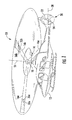
- FIG. 1 is a perspective view of an example embodiment of a helicopter 10 according to the present specification.
- helicopter 10 has a fuselage 12 and a main rotor assembly 14, which includes main rotor blades 16a-c and a main rotor shaft 18.
- Helicopter 10 may also include a tail rotor assembly 20, which generally includes tail rotor blades 22 and a tail rotor shaft 24.
- Main rotor blades 16a-c may rotate about a longitudinal axis 26 of main rotor shaft 18.
- Tail rotor blades may rotate about a longitudinal axis 28 of tail rotor shaft 24.
- flaps 32a-b and actuator systems 36a-b on main rotor blades 16a-b respectively. Not visible in Figure 1 are flap 32c and actuator system 36c on main rotor blade 16c.
- FIG. 2 is a partial top view of helicopter 10, including main rotor blade 16a, connected to a hub 30 on main rotor shaft 18.
- main rotor blade 16a may include additional active elements that may be used to manipulate aerodynamic surfaces, such as flap 32a.
- Flap 32a in the example embodiment of helicopter 10 is placed outboard along the trailing edge 34a, but may be placed in other positions according to particular design criteria.
- flap 32a is illustrated and described herein as a distinct component of main rotor blade 16a, it may also be any movable or flexible portion of main rotor blade 16a.
- actuator system 36a is also depicted in the cut-away section Figure 2 , generally oriented parallel to a span-wise axis 17a of main rotor blade 16a.
- main rotor blade 16a may rotate about hub 30, while actuator system manipulates flap 32a.
- the rotation causes a number of reactive forces, including lift and centrifugal forces (CF).
- FIG 3 is a simple top-view schematic of actuator system 36a in main rotor blade 16a.
- Actuator system 36a may include linear actuators 38a-b.
- Each linear actuator 38a-b typically includes a fixed or stationary element, such as stators 40a-b, and a moving or sliding element, such as sliders 42a-b.
- Stators 40a-b in the example embodiment are rigidly connected to the frame of main rotor blade 16a, and they may be identical elements or may have distinct properties for certain applications.
- sliders 42a-b may be identical or have distinct properties for certain applications.
- Linear actuators 38a-b each has an elongated shape with a lengthwise axis 39a-b that is generally oriented parallel with span-wise axis 17a of main rotor blade 16a.
- linear actuators 38a-b are also generally oriented parallel to each other along the span of main rotor blade 16a.
- Such a span-wise orientation is generally preferable to other orientations as it generally provides larger space in the blade for larger, more powerful motors with longer strokes, and better mass placement.
- crank 44 is connected to sliders 42a-b.
- Crank 44 includes a beam element 46, a pivot element 48, and an arm element 50.
- pivot element 48 include a conventional bearing with rolling elements, an elastomeric element, a sleeve bushing, or a structural flexure.
- Pivot element 48 may be positioned coincident with beam element 46, or may be offset a distance L relative to beam element 46, as shown in Figure 3 .
- the negative spring effect may counteract aerodynamic forces and reduce actuator power requirements, thereby also potentially reducing the mass of actuator system 36a.
- Arm element 50 may be rigidly attached to beam element 46, or beam element 46 and arm element may 50 be fabricated as a single element.
- FIG 4 is a simple side-view schematic of actuator system 36a.
- Stators 40a-b are preferably placed within the frame of main rotor blade 16a in parallel.
- Connecting rod 52 connects actuator system 36a to flap 32a through crank 44 (see Figure 3 ) and sliders 42a-b (see Figure 3 ).
- Flap 32a may rotate about an axis 33 in response to force from connecting rod 52. Alternate positions of flap 32a as it rotates about axis 33 are illustrated in phantom as flaps 32a-1 and 32a-2.
- FIG. 5 is a cut-away view of an example embodiment of a linear actuator 60.
- linear actuator 60 is an electromagnetic linear motor having a fixed element, stator 62, having electric coils, and an elongated, high-power permanent magnetic slider 64.
- the slider 64 moves and converts electrical power to useful work.
- the motion, position, and retention of slider 64 are controlled with electromagnetic force generated with the electric coils of stator 62.
- Such an actuator may provide benefits in certain applications where high bandwidth and large stroke with a small footprint are desirable.
- an electromagnetic motor such as linear actuator 60 may be advantageous in a helicopter rotor blade where vibrations and noise are counteracted with relatively small flap deflections at high frequency, but performance is enhanced with larger deflections at a lower frequency.
- Crank 44 is similar to a common bell crank, and as it rotates it converts the span-wise motion of sliders 42a-b into chord-wise motion that may be used to manipulate an active element, such as flap 32a, which is connected to arm element 50 through a connecting rod 52 or similar linkage.
- sliders 42a-b are actuated such that each reciprocates generally parallel to axis 17a and slider 42a moves opposite to slider 42b.
- slider 42a moves in the outboard direction of main rotor blade 16a
- slider 42b moves inboard.
- crank 44 rotates about pivot element 48, causing arm element 50 to advance toward trailing edge 34a of main rotor blade 16a.
- the movement of arm element 50 toward trailing edge 34a in turn causes connecting rod 52 to act on flap 32a, which may rotate about axis 33 to position 32a-1.
- crank 44 rotates in the opposite direction about pivot element 48, causing arm element 50 to retreat from trailing edge 34a.
- the movement of arm element 50 away from trailing edge 34b in turn causes connecting rod 52 to act on flap 32a, which may rotate about axis 33 to another position, such as 32a-2.
- FIG. 6 is a simple top-view schematic of another example embodiment of an actuator system 70 in a main rotor blade 72 according to the present specification.
- Actuator system 70 may include linear actuators 74a-b.
- Each linear actuator 74a-b typically includes a fixed or stationary element, such as stators 76a-b, and a moving element or sliding element, such as sliders 78a-b.
- Stators 76a-b in the example embodiment are rigidly connected to the frame of main rotor blade 72, and they may be identical elements or may have distinct properties for certain applications.
- sliders 78a-b may be identical or have distinct properties for certain applications.
- Linear actuators 74a-b each has an elongated shape with a lengthwise axis 75a-b that is generally oriented parallel with span-wise axis 73 of main rotor blade 72. In contrast to linear actuators 38a-b in Figure 3 , linear actuators 74a-b are generally oriented in series along the span of main rotor blade 72.
- crank 80 is connected to sliders 78a-b.
- Crank 80 includes a beam element 82, a pivot element 84, and an arm element 86.
- Extension elements 79a-b may be used to connect sliders 78a-b to beam element 82.
- Examples of pivot element 84 include a conventional bearing with rolling elements, an elastomeric element, a sleeve bushing, or a structural flexure.
- Pivot element 84 may be positioned coincident with beam element 82, or may be positioned a distance L relative to beam element 82, as shown in Figure 6 .
- the negative spring effect may counteract aerodynamic forces and reduce actuator power requirements, thereby also potentially reducing the mass of actuator system 70.
- Arm element 86 may be rigidly attached to beam element 82, or beam element 82 and arm element 86 may be fabricated as a single element.
- Crank 80 is similar to a common bell crank, and as it rotates it converts the span-wise motion of sliders 78a-b into chord-wise motion that may be used to manipulate an active element, such as flap 88, which is connected to arm element 86 through a connecting rod 90 or similar linkage.
- sliders 78a-b are actuated such that each reciprocates generally parallel to axis 73 and slider 78a moves opposite to slider 78b.
- slider 78a moves in the outboard direction of main rotor blade 72
- slider 78b moves inboard.
- crank 80 rotates about pivot element 84, causing arm element 86 to advance toward trailing edge 92 of main rotor blade 72.
- the movement of arm element 86 toward trailing edge 92 in turn causes connecting rod 90 to act on flap 88, which may rotate about axis 89.
- crank 80 rotates in the opposite direction about pivot element 84, causing arm element 86 to retreat from trailing edge 92.
- the movement of arm element 86 away from trailing edge 92 in turn causes connecting rod 90 to act on flap 88, which may rotate about axis 89.
- Figure 7 is a simple schematic of an example embodiment of an actuator system 100 having a cross-axis flexure pivot element, which may be deployed in a main rotor blade 101 or other wing structure having an active element 103.
- a cross-axis flexure pivot element may simulate a pinned joint while providing certain potential advantages over alternative elements, such as reducing weight and moving parts.
- a cross-axis flexure pivot element may also be advantageous where high frequency motion and low hysteresis is needed.
- Actuator system 100 may include moving or sliding elements, such as sliding elements 102a-b, which may be driven by input forces F1 and F2, respectively. Sliding elements 102a-b may be identical or have distinct properties for certain applications.
- Sliding elements 102a-b each has an elongated shape with a lengthwise axis 105a-b that may be oriented parallel with a span-wise axis 107 of main rotor blade 101.
- sliding elements 102a-b are also generally oriented parallel to each other along the span of main rotor blade 101.
- crank 104 may be connected to sliding elements 102a-b.
- Crank 104 includes a beam element 106, a cross-axis flexure pivot element 108, and arm elements 110a-b.
- Cross-axis flexure pivot element 108 may include flexure straps 112a-b, which may be made of fiberglass or other suitable flexure material. Each flexure strap 112a-b can be fastened on one end to crank 104, and on the other end to the frame of main rotor blade 101 or other fixture that may be rigidly attached to the frame.
- the flexure straps 112a-b intersect at a pivot point 113.
- Arm elements 110a-b may each be fastened to flexure straps 114a-b, respectively, which may in turn be fastened to sleeve elements 116a-b.
- the use of flexure straps 114a-b for connecting crank 104 to sleeve elements 116a-b allows transverse displacement between crank 104 and sliding elements 102a-b.
- Each sleeve element 116a-b may be fastened to a sliding element 102a-b, respectively.
- the length of flexure straps 114a-b may be adjusted to control the offset d3 between pivot point 113 and the points of attachment 115a-b with arm elements 110a-b.
- the offset d3 may be used advantageously to create a negative stiffness spring effect as discussed above.
- Arm elements 110a-b may be rigidly attached to beam element 106, or beam element 106 and arm elements 110a-b may be fabricated as a single element.
- a link element 118 may be fastened on one end to crank 104 and on the other to active element 103.
- sliding elements 102a-b may be actuated such that each reciprocates generally parallel to a span-wise axis of a wing structure and sliding element 102a moves opposite to sliding element 102b.
- sliding element 102a moves in the outboard direction of a main rotor blade
- sliding element 102b moves inboard.
- crank 104 may rotate about pivot point 113, causing beam element 106 to translate in a first direction (e.g., away from a trailing edge).
- the movement of beam element 106 in turn may cause link element 118 to act on active element 103, which may rotate about an axis 109.
- crank 104 may rotate in the opposite direction about pivot point 113, causing beam element 106 to translate in a second direction (e.g., toward a trailing edge).
- the movement of beam element 106 in turn may cause link element 118 to act on active element 103, which may rotate about axis 109.
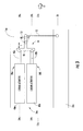
- FIG 8 is a simple schematic of an example embodiment of an actuator system 200 having a cross-axis flexure pivot element, which may be deployed in a main rotor blade 201 or other wing structure having an active element 203.
- Actuator system 200 may include moving or sliding elements, such as sliding elements 202a-b, which may be driven by input forces F1 and F2, respectively.
- Sliding elements 202a-b may be identical or have distinct properties for certain applications.
- Sliding elements 202a-b each has an elongated shape with a lengthwise axis 205a-b that may be oriented parallel with a span-wise axis 207 of main rotor blade 201.
- sliding elements 202a-b are also generally oriented in series with each other along the span of main rotor blade 201.
- a crank 204 may be connected to sliding elements 202a-b.
- Crank 204 includes a beam element 206, a cross-axis flexure pivot element 208, and arm elements 210a-b.
- Cross-axis flexure pivot element 208 may include flexure straps 212a-b, which may be made of fiberglass or other suitable flexure material.
- Each flexure strap 212a-b may be fastened on one end to crank 204, and on the other end to the frame of main rotor blade 201 or other fixture that may be rigidly attached to the frame.
- the flexure straps 212a-b intersect at a pivot point 213.
- Arm elements 210a-b may be each fastened to flexure straps 214a-b, respectively, which may be in turn fastened to sleeve elements 216a-b.
- the use of flexure straps 214a-b for connecting crank 204 to sleeve elements 216a-b allows transverse displacement between crank 204 and sliding elements 202a-b.
- Each sleeve element 216a-b may be fastened to a sliding element 202a-b, respectively.
- the length of flexure straps 214a-b may be adjusted to control the offset d3 between pivot point 213 and the points of attachment 215a-b with arm elements 210a-b.
- the offset d3 may be used advantageously to create a negative stiffness spring effect as discussed above.
- Arm elements 210a-b may be rigidly attached to beam element 206, or beam element 206 and arm elements 210a-b may be fabricated as a single element.
- a link element 218 may be fastened on one end to crank 204 and on the other to active element 203.
- sliding elements 202a-b may be actuated such that each reciprocates generally parallel to a span-wise axis of a wing structure and sliding element 202a moves opposite to sliding element 202b.
- sliding element 202a moves in the outboard direction of a main rotor blade
- sliding element 202b moves inboard.
- crank 204 may rotate about pivot point 213, causing beam element 206 to translate in a first direction (e.g., away from a trailing edge).
- the movement of beam element 206 in turn may cause link element 218 to act on active element 203, which may rotate about an axis 209.
- crank 204 rotates in the opposite direction about pivot point 213, causing beam element 206 to translate in a second direction (e.g., toward a trailing edge).
- the movement of beam element 206 in turn causes link element 218 to act on active element 203, which may rotate about axis 209.
- FIG 9 is a perspective view of an example embodiment of an assembled actuator system 300 according to the present specification.
- Actuator system 300 is representative of a system having a parallel configuration of linear actuators, similar to the system illustrated in Figure 3 or Figure 7 .
- actuator system 300 includes a crank 304, a base 306, and a pivot element 308.
- Pivot element 308 generally includes flexure straps 312a-b, which may be fastened or clamped on one end to crank 304 with fasteners 305a-d and on the other to base 306.
- Base 306 may be fastened to a wing frame (not shown) with bolts 307a-b.
- Each sleeve element 316a-b may be fastened near one end to a sliding element (not visible) and near the other end to another flexure strap (not visible). Similar to flexure straps 114a-b in Figure 7 , these flexure straps may be fastened on the other end to crank 304. Sleeve element 316a may further include a hole 317 to permit passage of a link element 318 from crank 304 to an active element (not shown).
- FIG 10 is a perspective view of another example embodiment of an assembled actuator system 400 according to the present specification.
- Actuator system 400 is representative of a system having a serial configuration of linear actuators, similar to the system illustrated in Figure 6 or Figure 8 .
- actuator system 400 includes a crank 404, a base 406, and a pivot element 408.
- Pivot element 408 generally includes flexure straps 412a-b, which may be fastened or clamped on one end to crank 404 and on the other to base 406.
- Each sleeve element 416a-b may be fastened near one end to a sliding element 402a-b, respectively, and near the other end to another flexure strap 414a-b, respectively. Similar to flexure straps 214a-b in Figure 8 , these flexure straps may be fastened on the other end to crank 404.
- FIG 11 is a top view of an example embodiment of an actuator system 500, according to the present specification.
- Actuator system 500 is representative of a system having a parallel configuration of linear actuators, similar to the system illustrated in Figure 9 .
- actuator system 500 includes a crank 504, a base 506, and a pivot element 508.
- Crank 504 is configured with multiple attachment points 515a-d, and may include a beam element 506 and arm elements 510a-b.
- Pivot element 508 generally includes flexure straps 512a-b, which may be fastened or clamped at attachment points 515c-d to crank 504 with fasteners 505a-b and at attachment points 515e-f to base 506 with fasteners 505c-d.
- Flexure straps 512a-b intersect at a pivot point 513, and the length of flexure straps 512a-b may be adjusted to control the offset between pivot point 513 and attachment points 515e-f.
- the offset may be used advantageously to create a negative stiffness spring effect as discussed above.
- Base 506 may be fastened to a wing frame (not shown) with bolts, such as bolt 507.
- Each sleeve element 516a-b is fastened near one end to a sliding element 502a-b, respectively, and near the other end to flexure straps 514a-b, respectively.
- Flexure straps 514a-b may also be fastened to crank 504 with fasteners 505e-f at attachment points 515a-b, respectively.
- Shoe elements 520a-d may be used to control curvature and bending strain.
- Sleeve element 516b may further include a hole (not visible) to permit passage of a link element 518 from crank 504 to an active element (
- FIG 12 is an exploded top view of an actuator system 600, according to the present specification.
- Actuator system 600 is also representative of a system having a parallel configuration of linear actuators.
- actuator system 600 includes linear actuators 602a-b, a crank 604, a base 606, and a pivot element 608.
- Pivot element 608 generally includes flexure straps 612a-b, which may be fastened or clamped on one end to crank 604 with fasteners 605a-b and on the other to base 606 with fasteners 605c-d.
- Base 606 may be fastened to a wing frame (not shown) by inserting bolts (not shown) through holes 607a-b.
- Each sleeve element 616a-b may be fastened near one end to a sliding element 602a-b, respectively, and near the other end to flexure straps 614a-b, respectively. Flexure straps 614a-b may also be fastened to crank 604 with fasteners 605e-f. Shoe elements 620a-d may be used to control curvature and bending strain. Sleeve element 616b may further include a hole (not visible) to permit passage of a link element 618 from crank 604 to an active element (not shown).
- Figure 13 is an exploded bottom view of actuator system 600.
- an actuator system may include hydraulic, piezoelectric, or electromechanical components.
- a linear actuator may have a fixed element such as a hydraulic cylinder and a moving element such as a hydraulic ram.
- the system and apparatus described herein provides significant advantages, including: (1) reducing or eliminating the adverse effects of centrifugal forces on linear actuators in a span-wise orientation; (2) more powerful motors; (3) longer stroke and greater bandwidth than other systems; and (4) improved mass distribution characteristics.
Landscapes
- Engineering & Computer Science (AREA)
- Mechanical Engineering (AREA)
- Aviation & Aerospace Engineering (AREA)
- General Engineering & Computer Science (AREA)
- Transmission Devices (AREA)
- Automation & Control Theory (AREA)
- Structures Of Non-Positive Displacement Pumps (AREA)
Claims (12)
- Appareil (100, 200, 300, 400, 500, 600) pour actionner un élément mobile sur un élément d'aile (101, 201), comprenant :une base (306, 406, 506),un premier vérin linéaire (38a, 60, 74a, 602a) ayant un premier élément fixe (62) etun premier élément coulissant (42a, 78, 102a, 202a, 402, 602a) mobile à l'intérieur de la base,un deuxième vérin linéaire (38b, 60, 74b, 602b) ayant un deuxième élément fixe et un deuxième élément de glissement (42b, 78b, 102b, 202b, 402b, 602b) pouvant se déplacer à l'intérieur de la base ;un élément de manivelle (44, 80, 104, 204, 304, 404, 504, 604) couplé à un élément de bielle (118, 218, 318, 418, 518, 618) à un emplacement de fixation de bielle, l'élément de bielle s'étendant sensiblement dans le sens de la corde, l'élément de bielle étant fonctionnellement associable avec l'élément mobile,un premier élément de corps du rivet (116a, 216a, 316a, 416a, 516a, 616a) connecté au premier élément de glissement et à l'élément de manivelle,un deuxième élément de corps du rivet (116b, 216b, 316b, 416b, 516b, 616b) connecté au deuxième élément coulissant et à l'élément de manivelle, caractérisé en ce que l'appareil comprend en outre :un élément de pivot élastique d'axe transversal (108, 208, 308, 408, 508, 608) comprenant :une première sangle de flexion (112a, 212a, 312a, 412a, 512a, 612a) et une deuxième sangle de flexion (112b, 212b, 312b, 412b, 512b, 612b) connectées chacune à la base et à l'élément de manivelle de telle sorte que la première sangle de flexion et la deuxième sangle de flexion se traversent en diagonale l'une et l'autre à un point d'articulation (113, 213, 513), le point d'articulation étant situé à une certaine distance de l'emplacement de fixation de bielle dans une direction approximativement dans le sens de l'envergure.
- Appareil selon la revendication 1, dans lequel la première sangle de flexion est reliée à la base au premier point de fixation de faisceau (505c, 605e) et la deuxième sangle de flexion est reliée à la base à un deuxième point de fixation de faisceau (505d, 605f).
- Aéronef (10), comprenant :un fuselage (12) ;une aile (16) ayant un axe d'articulation de pas, un cadre monté sur le fuselage, et un élément actif (32a, 88, 103, 203) ;un appareil selon la revendication 1 ou la revendication 2, dans lequel la base est reliée au cadre, etl'élément de bielle est relié à une première extrémité de l'élément de manivelle et sur une deuxième extrémité de l'élément actif.
- Aéronef selon la revendication 3, dans lequel le premier élément de glissement et le deuxième élément de glissement sont alignés pour être mobiles le long d'un axe parallèle à l'axe d'articulation de pas de l'aile.
- Aéronef selon la revendication 3 ou la revendication 4, dans lequel l'aile peut tourner autour d'un moyeu (30) relié au fuselage.
- Aéronef selon la revendication 3 ou la revendication 4, dans lequel l'aile peut tourner autour d'un moyeu (30) relié au fuselage et le premier élément de glissement et le deuxième élément de glissement sont alignés pour être mobiles le long d'un axe parallèle à l'axe d'articulation de pas de l'aile.
- Aéronef selon l'une quelconque des revendications 3 à 6, dans lequel le premier vérin linéaire et le deuxième vérin linéaire sont des moteurs électromagnétiques (60) ; ou
appareil selon la revendication 1 ou la revendication 2, dans lequel le premier vérin linéaire et le deuxième vérin linéaire sont des vérins électromagnétiques (60). - Aéronef ou appareil selon l'une quelconque des revendications précédentes, dans lequel le premier vérin linéaire est aligné parallèlement au deuxième vérin linéaire.
- Aéronef ou appareil selon l'une quelconque des revendications 1 à 8, dans lequel le premier vérin linéaire est aligné en série avec le deuxième vérin linéaire.
- Aéronef selon la revendication 3 ou selon l'une quelconque des revendications précédentes, dans lequel :l'aile est orientable autour d'un moyeu (30) relié au fuselage,le premier élément de glissement et le deuxième élément de glissement sont alignés pour être mobiles le long d'un axe parallèle à l'axe d'articulation de pas de l'aile, et le premier vérin linéaire est aligné parallèlement au deuxième vérin linéaire.
- Aéronef selon la revendication 10, dans lequel :l'élément de pivot élastique transversal comprend un point de pivot décalé (d3).
- Aéronef selon la revendication 3 ou selon l'une quelconque des revendications précédentes, dans lequel :l'aile est susceptible de tourner autour d'un moyeu (30) relié au fuselage ;le premier élément de glissement et le deuxième élément de glissement sont alignés pour être mobiles le long d'un axe parallèle à l'axe d'articulation de pas de l'aile ;le premier vérin linéaire est aligné en série avec le deuxième vérin linéaire ; etl'élément de pivot élastique transversal comprend un point de pivot décalé (d3).
Applications Claiming Priority (2)
| Application Number | Priority Date | Filing Date | Title |
|---|---|---|---|
| PCT/US2010/054910 WO2012060806A1 (fr) | 2010-11-01 | 2010-11-01 | Procédé et appareil pour la manipulation active de surfaces aérodynamiques |
| PCT/US2010/055367 WO2012060836A1 (fr) | 2010-11-01 | 2010-11-04 | Procédé et appareil pour la manipulation active de surfaces aérodynamiques |
Publications (3)
| Publication Number | Publication Date |
|---|---|
| EP2616332A1 EP2616332A1 (fr) | 2013-07-24 |
| EP2616332A4 EP2616332A4 (fr) | 2013-08-14 |
| EP2616332B1 true EP2616332B1 (fr) | 2014-05-07 |
Family
ID=46024721
Family Applications (2)
| Application Number | Title | Priority Date | Filing Date |
|---|---|---|---|
| EP10859345.0A Active EP2616334B1 (fr) | 2010-11-01 | 2010-11-01 | Appareil pour la manipulation active de surfaces aérodynamiques |
| EP10859373.2A Active EP2616332B1 (fr) | 2010-11-01 | 2010-11-04 | Appareil pour la manipulation active de surfaces aérodynamiques |
Family Applications Before (1)
| Application Number | Title | Priority Date | Filing Date |
|---|---|---|---|
| EP10859345.0A Active EP2616334B1 (fr) | 2010-11-01 | 2010-11-01 | Appareil pour la manipulation active de surfaces aérodynamiques |
Country Status (4)
| Country | Link |
|---|---|
| US (1) | US8657229B2 (fr) |
| EP (2) | EP2616334B1 (fr) |
| CA (3) | CA2925877C (fr) |
| WO (2) | WO2012060806A1 (fr) |
Families Citing this family (8)
| Publication number | Priority date | Publication date | Assignee | Title |
|---|---|---|---|---|
| US9180966B2 (en) * | 2012-08-28 | 2015-11-10 | Bell Helicopter Textron Inc. | Actuation system for an active element in a rotor blade |
| US9180965B2 (en) * | 2012-08-28 | 2015-11-10 | Bell Helicopter Textron Inc. | Actuation system for an active element in a rotor blade |
| US10000283B2 (en) * | 2013-03-14 | 2018-06-19 | William L. Hinks | Negative spring compensation for elastomeric bearing torque |
| US9523278B2 (en) * | 2013-10-11 | 2016-12-20 | Bell Helicopter Textron Inc. | Actuation system for an active blade element of a rotor blade |
| US10023304B2 (en) * | 2014-05-23 | 2018-07-17 | Bell Helicopter Textron Inc. | Tail rotor actuation system |
| US10053215B2 (en) * | 2015-02-03 | 2018-08-21 | Bell Helicopter Textron Inc. | Electro-hydraulic on-blade actuation system |
| DE102021004136B4 (de) * | 2021-08-09 | 2023-03-09 | Friedrich B. Grimm | Vorrichtung für ein Drehflügelfahrzeug oder für eine Drehflügelturbine |
| WO2024049387A1 (fr) * | 2022-08-31 | 2024-03-07 | Tusas- Turk Havacilik Ve Uzay Sanayii Anonim Sirketi | Véhicule aérien |
Family Cites Families (14)
| Publication number | Priority date | Publication date | Assignee | Title |
|---|---|---|---|---|
| US2415128A (en) * | 1943-07-30 | 1947-02-04 | Bendix Westinghouse Automotive | Fluid pressure control mechanism |
| US2457508A (en) | 1945-07-09 | 1948-12-28 | Todd Edgar Bernard | Aircraft control system for control surfaces and wheel brakes |
| US2612329A (en) | 1948-11-13 | 1952-09-30 | Northrop Aircraft Inc | Aileron, flap, and dive brake |
| US2852209A (en) * | 1955-10-14 | 1958-09-16 | Acrophysics Dev Corp | Aircraft control surface deflection apparatus |
| GB1144255A (en) | 1966-11-18 | 1969-03-05 | Hobson Ltd H M | Improvements in feel simulators for aircraft |
| US6220551B1 (en) * | 1998-01-14 | 2001-04-24 | Manuel Munoz Saiz | Flight controls with automatic balance |
| JP3053620B1 (ja) | 1999-02-25 | 2000-06-19 | 株式会社コミュータヘリコプタ先進技術研究所 | ロ―タブレ―ドのフラップ駆動装置 |
| JP3004644B1 (ja) | 1999-03-03 | 2000-01-31 | 株式会社コミュータヘリコプタ先進技術研究所 | ロ―タブレ―ドのフラップ駆動装置 |
| US6513762B2 (en) | 1999-05-18 | 2003-02-04 | Diversified Technologies, Inc. | Flap actuator system |
| JP3168198B2 (ja) | 1999-08-20 | 2001-05-21 | 株式会社コミュータヘリコプタ先進技術研究所 | フラップ駆動装置およびロータブレード |
| US7931240B2 (en) | 2006-08-11 | 2011-04-26 | Techno-Sciences, Inc. | Cellular support structures used for controlled actuation of fluid contact surfaces |
| US7837144B2 (en) | 2006-08-11 | 2010-11-23 | Techno-Sciences, Inc. | Fluid-driven artificial muscles as mechanisms for controlled actuation |
| US7762770B2 (en) * | 2006-12-14 | 2010-07-27 | Sikorsky Aircraft Corporation | Hybrid actuator for helicopter rotor blade control flaps |
| US8087316B2 (en) * | 2007-02-28 | 2012-01-03 | Edward George Holtgraver | Flat yoke valve actuator |
-
2010
- 2010-11-01 WO PCT/US2010/054910 patent/WO2012060806A1/fr active Application Filing
- 2010-11-01 EP EP10859345.0A patent/EP2616334B1/fr active Active
- 2010-11-01 CA CA2925877A patent/CA2925877C/fr active Active
- 2010-11-01 US US13/703,813 patent/US8657229B2/en active Active
- 2010-11-01 CA CA2813952A patent/CA2813952C/fr active Active
- 2010-11-04 CA CA2814493A patent/CA2814493C/fr active Active
- 2010-11-04 EP EP10859373.2A patent/EP2616332B1/fr active Active
- 2010-11-04 WO PCT/US2010/055367 patent/WO2012060836A1/fr active Application Filing
Also Published As
| Publication number | Publication date |
|---|---|
| EP2616334B1 (fr) | 2014-04-23 |
| EP2616334A4 (fr) | 2013-11-06 |
| CA2925877A1 (fr) | 2012-05-10 |
| US20130082136A1 (en) | 2013-04-04 |
| CA2814493A1 (fr) | 2012-05-10 |
| EP2616332A4 (fr) | 2013-08-14 |
| CA2813952A1 (fr) | 2012-05-10 |
| US8657229B2 (en) | 2014-02-25 |
| EP2616332A1 (fr) | 2013-07-24 |
| WO2012060806A1 (fr) | 2012-05-10 |
| EP2616334A1 (fr) | 2013-07-24 |
| CA2813952C (fr) | 2016-11-22 |
| WO2012060836A1 (fr) | 2012-05-10 |
| CA2814493C (fr) | 2017-12-05 |
| CA2925877C (fr) | 2018-03-27 |
Similar Documents
| Publication | Publication Date | Title |
|---|---|---|
| EP2616332B1 (fr) | Appareil pour la manipulation active de surfaces aérodynamiques | |
| US8657228B2 (en) | Method and apparatus for actively manipulating aerodynamic surfaces | |
| US6938853B2 (en) | Biomimetic mechanism for micro aircraft | |
| CA2838512C (fr) | Moyeu de rotor destine a etre utilise avec des pales a inertie elevee | |
| JP5284794B2 (ja) | 航空機用の引き込み可能な揚力ブレード | |
| EP1957362B1 (fr) | Actionneur linéaire ou rotatif pour commande de rotor d'hélicoptère, à base d'un moteur sans balai à courant continu (bldc) | |
| EP1957363B1 (fr) | Systeme de commande de giravion et procede d'utilisation correspondant | |
| US6659397B1 (en) | Control system for ornithopter | |
| EP2703286B1 (fr) | Système d'actionnement pour un élément actif dans une pale de rotor | |
| KR20170141182A (ko) | 트레일링 에지 플랩을 갖는 헬리콥터 에어로포일 | |
| KR20120118426A (ko) | 액티브 거니 플랩 | |
| EP2703285B1 (fr) | Système d'actionnement pour un élément actif dans une pale de rotor | |
| US11365000B2 (en) | Rotorcraft including variable blade torsional angle mechanism | |
| EP2487108B1 (fr) | Dispositif modulaire intégré pour le contrôle d'une pale de rotor | |
| NL2029203B1 (en) | Actuation device for actuating a high-lift device of a rotor blade | |
| Pines et al. | Biomimetic mechanism for micro aircraft |
Legal Events
| Date | Code | Title | Description |
|---|---|---|---|
| PUAI | Public reference made under article 153(3) epc to a published international application that has entered the european phase |
Free format text: ORIGINAL CODE: 0009012 |
|
| 17P | Request for examination filed |
Effective date: 20130415 |
|
| AK | Designated contracting states |
Kind code of ref document: A1 Designated state(s): AL AT BE BG CH CY CZ DE DK EE ES FI FR GB GR HR HU IE IS IT LI LT LU LV MC MK MT NL NO PL PT RO RS SE SI SK SM TR |
|
| A4 | Supplementary search report drawn up and despatched |
Effective date: 20130712 |
|
| RIC1 | Information provided on ipc code assigned before grant |
Ipc: F16H 21/44 20060101ALI20130708BHEP Ipc: B64C 13/38 20060101ALI20130708BHEP Ipc: B64C 27/615 20060101AFI20130708BHEP Ipc: B64C 27/72 20060101ALI20130708BHEP |
|
| REG | Reference to a national code |
Ref country code: DE Ref legal event code: R079 Ref document number: 602010016021 Country of ref document: DE Free format text: PREVIOUS MAIN CLASS: B64C0027000000 Ipc: B64C0013300000 |
|
| DAX | Request for extension of the european patent (deleted) | ||
| GRAP | Despatch of communication of intention to grant a patent |
Free format text: ORIGINAL CODE: EPIDOSNIGR1 |
|
| RIC1 | Information provided on ipc code assigned before grant |
Ipc: B64C 27/72 20060101ALI20140204BHEP Ipc: B64C 27/615 20060101ALI20140204BHEP Ipc: B64C 27/00 20060101ALI20140204BHEP Ipc: B64C 13/30 20060101AFI20140204BHEP |
|
| INTG | Intention to grant announced |
Effective date: 20140306 |
|
| GRAS | Grant fee paid |
Free format text: ORIGINAL CODE: EPIDOSNIGR3 |
|
| GRAA | (expected) grant |
Free format text: ORIGINAL CODE: 0009210 |
|
| AK | Designated contracting states |
Kind code of ref document: B1 Designated state(s): AL AT BE BG CH CY CZ DE DK EE ES FI FR GB GR HR HU IE IS IT LI LT LU LV MC MK MT NL NO PL PT RO RS SE SI SK SM TR |
|
| REG | Reference to a national code |
Ref country code: GB Ref legal event code: FG4D |
|
| REG | Reference to a national code |
Ref country code: AT Ref legal event code: REF Ref document number: 666429 Country of ref document: AT Kind code of ref document: T Effective date: 20140515 |
|
| REG | Reference to a national code |
Ref country code: IE Ref legal event code: FG4D |
|
| REG | Reference to a national code |
Ref country code: DE Ref legal event code: R096 Ref document number: 602010016021 Country of ref document: DE Effective date: 20140618 |
|
| REG | Reference to a national code |
Ref country code: AT Ref legal event code: MK05 Ref document number: 666429 Country of ref document: AT Kind code of ref document: T Effective date: 20140507 |
|
| REG | Reference to a national code |
Ref country code: NL Ref legal event code: VDEP Effective date: 20140507 |
|
| REG | Reference to a national code |
Ref country code: LT Ref legal event code: MG4D |
|
| PG25 | Lapsed in a contracting state [announced via postgrant information from national office to epo] |
Ref country code: CY Free format text: LAPSE BECAUSE OF FAILURE TO SUBMIT A TRANSLATION OF THE DESCRIPTION OR TO PAY THE FEE WITHIN THE PRESCRIBED TIME-LIMIT Effective date: 20140507 Ref country code: NO Free format text: LAPSE BECAUSE OF FAILURE TO SUBMIT A TRANSLATION OF THE DESCRIPTION OR TO PAY THE FEE WITHIN THE PRESCRIBED TIME-LIMIT Effective date: 20140807 Ref country code: GR Free format text: LAPSE BECAUSE OF FAILURE TO SUBMIT A TRANSLATION OF THE DESCRIPTION OR TO PAY THE FEE WITHIN THE PRESCRIBED TIME-LIMIT Effective date: 20140808 Ref country code: LT Free format text: LAPSE BECAUSE OF FAILURE TO SUBMIT A TRANSLATION OF THE DESCRIPTION OR TO PAY THE FEE WITHIN THE PRESCRIBED TIME-LIMIT Effective date: 20140507 Ref country code: IS Free format text: LAPSE BECAUSE OF FAILURE TO SUBMIT A TRANSLATION OF THE DESCRIPTION OR TO PAY THE FEE WITHIN THE PRESCRIBED TIME-LIMIT Effective date: 20140907 Ref country code: FI Free format text: LAPSE BECAUSE OF FAILURE TO SUBMIT A TRANSLATION OF THE DESCRIPTION OR TO PAY THE FEE WITHIN THE PRESCRIBED TIME-LIMIT Effective date: 20140507 |
|
| PG25 | Lapsed in a contracting state [announced via postgrant information from national office to epo] |
Ref country code: PL Free format text: LAPSE BECAUSE OF FAILURE TO SUBMIT A TRANSLATION OF THE DESCRIPTION OR TO PAY THE FEE WITHIN THE PRESCRIBED TIME-LIMIT Effective date: 20140507 Ref country code: SE Free format text: LAPSE BECAUSE OF FAILURE TO SUBMIT A TRANSLATION OF THE DESCRIPTION OR TO PAY THE FEE WITHIN THE PRESCRIBED TIME-LIMIT Effective date: 20140507 Ref country code: RS Free format text: LAPSE BECAUSE OF FAILURE TO SUBMIT A TRANSLATION OF THE DESCRIPTION OR TO PAY THE FEE WITHIN THE PRESCRIBED TIME-LIMIT Effective date: 20140507 Ref country code: HR Free format text: LAPSE BECAUSE OF FAILURE TO SUBMIT A TRANSLATION OF THE DESCRIPTION OR TO PAY THE FEE WITHIN THE PRESCRIBED TIME-LIMIT Effective date: 20140507 Ref country code: LV Free format text: LAPSE BECAUSE OF FAILURE TO SUBMIT A TRANSLATION OF THE DESCRIPTION OR TO PAY THE FEE WITHIN THE PRESCRIBED TIME-LIMIT Effective date: 20140507 Ref country code: ES Free format text: LAPSE BECAUSE OF FAILURE TO SUBMIT A TRANSLATION OF THE DESCRIPTION OR TO PAY THE FEE WITHIN THE PRESCRIBED TIME-LIMIT Effective date: 20140507 Ref country code: AT Free format text: LAPSE BECAUSE OF FAILURE TO SUBMIT A TRANSLATION OF THE DESCRIPTION OR TO PAY THE FEE WITHIN THE PRESCRIBED TIME-LIMIT Effective date: 20140507 |
|
| PG25 | Lapsed in a contracting state [announced via postgrant information from national office to epo] |
Ref country code: PT Free format text: LAPSE BECAUSE OF FAILURE TO SUBMIT A TRANSLATION OF THE DESCRIPTION OR TO PAY THE FEE WITHIN THE PRESCRIBED TIME-LIMIT Effective date: 20140908 |
|
| PG25 | Lapsed in a contracting state [announced via postgrant information from national office to epo] |
Ref country code: BE Free format text: LAPSE BECAUSE OF FAILURE TO SUBMIT A TRANSLATION OF THE DESCRIPTION OR TO PAY THE FEE WITHIN THE PRESCRIBED TIME-LIMIT Effective date: 20140507 Ref country code: DK Free format text: LAPSE BECAUSE OF FAILURE TO SUBMIT A TRANSLATION OF THE DESCRIPTION OR TO PAY THE FEE WITHIN THE PRESCRIBED TIME-LIMIT Effective date: 20140507 Ref country code: EE Free format text: LAPSE BECAUSE OF FAILURE TO SUBMIT A TRANSLATION OF THE DESCRIPTION OR TO PAY THE FEE WITHIN THE PRESCRIBED TIME-LIMIT Effective date: 20140507 Ref country code: CZ Free format text: LAPSE BECAUSE OF FAILURE TO SUBMIT A TRANSLATION OF THE DESCRIPTION OR TO PAY THE FEE WITHIN THE PRESCRIBED TIME-LIMIT Effective date: 20140507 Ref country code: SK Free format text: LAPSE BECAUSE OF FAILURE TO SUBMIT A TRANSLATION OF THE DESCRIPTION OR TO PAY THE FEE WITHIN THE PRESCRIBED TIME-LIMIT Effective date: 20140507 Ref country code: RO Free format text: LAPSE BECAUSE OF FAILURE TO SUBMIT A TRANSLATION OF THE DESCRIPTION OR TO PAY THE FEE WITHIN THE PRESCRIBED TIME-LIMIT Effective date: 20140507 |
|
| REG | Reference to a national code |
Ref country code: DE Ref legal event code: R097 Ref document number: 602010016021 Country of ref document: DE |
|
| PG25 | Lapsed in a contracting state [announced via postgrant information from national office to epo] |
Ref country code: NL Free format text: LAPSE BECAUSE OF FAILURE TO SUBMIT A TRANSLATION OF THE DESCRIPTION OR TO PAY THE FEE WITHIN THE PRESCRIBED TIME-LIMIT Effective date: 20140507 |
|
| PLBE | No opposition filed within time limit |
Free format text: ORIGINAL CODE: 0009261 |
|
| STAA | Information on the status of an ep patent application or granted ep patent |
Free format text: STATUS: NO OPPOSITION FILED WITHIN TIME LIMIT |
|
| 26N | No opposition filed |
Effective date: 20150210 |
|
| REG | Reference to a national code |
Ref country code: DE Ref legal event code: R097 Ref document number: 602010016021 Country of ref document: DE Effective date: 20150210 |
|
| PG25 | Lapsed in a contracting state [announced via postgrant information from national office to epo] |
Ref country code: MC Free format text: LAPSE BECAUSE OF FAILURE TO SUBMIT A TRANSLATION OF THE DESCRIPTION OR TO PAY THE FEE WITHIN THE PRESCRIBED TIME-LIMIT Effective date: 20140507 Ref country code: LU Free format text: LAPSE BECAUSE OF FAILURE TO SUBMIT A TRANSLATION OF THE DESCRIPTION OR TO PAY THE FEE WITHIN THE PRESCRIBED TIME-LIMIT Effective date: 20141104 |
|
| REG | Reference to a national code |
Ref country code: CH Ref legal event code: PL |
|
| PG25 | Lapsed in a contracting state [announced via postgrant information from national office to epo] |
Ref country code: LI Free format text: LAPSE BECAUSE OF NON-PAYMENT OF DUE FEES Effective date: 20141130 Ref country code: SI Free format text: LAPSE BECAUSE OF FAILURE TO SUBMIT A TRANSLATION OF THE DESCRIPTION OR TO PAY THE FEE WITHIN THE PRESCRIBED TIME-LIMIT Effective date: 20140507 Ref country code: CH Free format text: LAPSE BECAUSE OF NON-PAYMENT OF DUE FEES Effective date: 20141130 |
|
| REG | Reference to a national code |
Ref country code: IE Ref legal event code: MM4A |
|
| PG25 | Lapsed in a contracting state [announced via postgrant information from national office to epo] |
Ref country code: IE Free format text: LAPSE BECAUSE OF NON-PAYMENT OF DUE FEES Effective date: 20141104 |
|
| REG | Reference to a national code |
Ref country code: FR Ref legal event code: PLFP Year of fee payment: 6 |
|
| PG25 | Lapsed in a contracting state [announced via postgrant information from national office to epo] |
Ref country code: SM Free format text: LAPSE BECAUSE OF FAILURE TO SUBMIT A TRANSLATION OF THE DESCRIPTION OR TO PAY THE FEE WITHIN THE PRESCRIBED TIME-LIMIT Effective date: 20140507 |
|
| PG25 | Lapsed in a contracting state [announced via postgrant information from national office to epo] |
Ref country code: BG Free format text: LAPSE BECAUSE OF FAILURE TO SUBMIT A TRANSLATION OF THE DESCRIPTION OR TO PAY THE FEE WITHIN THE PRESCRIBED TIME-LIMIT Effective date: 20140507 |
|
| PG25 | Lapsed in a contracting state [announced via postgrant information from national office to epo] |
Ref country code: MT Free format text: LAPSE BECAUSE OF FAILURE TO SUBMIT A TRANSLATION OF THE DESCRIPTION OR TO PAY THE FEE WITHIN THE PRESCRIBED TIME-LIMIT Effective date: 20140507 Ref country code: TR Free format text: LAPSE BECAUSE OF FAILURE TO SUBMIT A TRANSLATION OF THE DESCRIPTION OR TO PAY THE FEE WITHIN THE PRESCRIBED TIME-LIMIT Effective date: 20140507 Ref country code: HU Free format text: LAPSE BECAUSE OF FAILURE TO SUBMIT A TRANSLATION OF THE DESCRIPTION OR TO PAY THE FEE WITHIN THE PRESCRIBED TIME-LIMIT; INVALID AB INITIO Effective date: 20101104 |
|
| REG | Reference to a national code |
Ref country code: FR Ref legal event code: PLFP Year of fee payment: 7 |
|
| REG | Reference to a national code |
Ref country code: FR Ref legal event code: PLFP Year of fee payment: 8 |
|
| PG25 | Lapsed in a contracting state [announced via postgrant information from national office to epo] |
Ref country code: MK Free format text: LAPSE BECAUSE OF FAILURE TO SUBMIT A TRANSLATION OF THE DESCRIPTION OR TO PAY THE FEE WITHIN THE PRESCRIBED TIME-LIMIT Effective date: 20140507 |
|
| PG25 | Lapsed in a contracting state [announced via postgrant information from national office to epo] |
Ref country code: AL Free format text: LAPSE BECAUSE OF FAILURE TO SUBMIT A TRANSLATION OF THE DESCRIPTION OR TO PAY THE FEE WITHIN THE PRESCRIBED TIME-LIMIT Effective date: 20140507 |
|
| P01 | Opt-out of the competence of the unified patent court (upc) registered |
Effective date: 20230602 |
|
| PGFP | Annual fee paid to national office [announced via postgrant information from national office to epo] |
Ref country code: GB Payment date: 20231127 Year of fee payment: 14 |
|
| PGFP | Annual fee paid to national office [announced via postgrant information from national office to epo] |
Ref country code: IT Payment date: 20231122 Year of fee payment: 14 Ref country code: FR Payment date: 20231127 Year of fee payment: 14 Ref country code: DE Payment date: 20231129 Year of fee payment: 14 |