EP2616263B1 - Fahrzeug mit über hydraulikmotoren betätigten antriebs- und steuerrädern - Google Patents
Fahrzeug mit über hydraulikmotoren betätigten antriebs- und steuerrädern Download PDFInfo
- Publication number
- EP2616263B1 EP2616263B1 EP10770621.0A EP10770621A EP2616263B1 EP 2616263 B1 EP2616263 B1 EP 2616263B1 EP 10770621 A EP10770621 A EP 10770621A EP 2616263 B1 EP2616263 B1 EP 2616263B1
- Authority
- EP
- European Patent Office
- Prior art keywords
- hydraulic
- free end
- vehicle
- wheel
- rigid
- Prior art date
- Legal status (The legal status is an assumption and is not a legal conclusion. Google has not performed a legal analysis and makes no representation as to the accuracy of the status listed.)
- Active
Links
Images


Classifications
-
- B—PERFORMING OPERATIONS; TRANSPORTING
- B60—VEHICLES IN GENERAL
- B60K—ARRANGEMENT OR MOUNTING OF PROPULSION UNITS OR OF TRANSMISSIONS IN VEHICLES; ARRANGEMENT OR MOUNTING OF PLURAL DIVERSE PRIME-MOVERS IN VEHICLES; AUXILIARY DRIVES FOR VEHICLES; INSTRUMENTATION OR DASHBOARDS FOR VEHICLES; ARRANGEMENTS IN CONNECTION WITH COOLING, AIR INTAKE, GAS EXHAUST OR FUEL SUPPLY OF PROPULSION UNITS IN VEHICLES
- B60K17/00—Arrangement or mounting of transmissions in vehicles
- B60K17/04—Arrangement or mounting of transmissions in vehicles characterised by arrangement, location or kind of gearing
- B60K17/14—Arrangement or mounting of transmissions in vehicles characterised by arrangement, location or kind of gearing the motor of fluid or electric gearing being disposed in, or adjacent to, traction wheel
-
- B—PERFORMING OPERATIONS; TRANSPORTING
- B60—VEHICLES IN GENERAL
- B60K—ARRANGEMENT OR MOUNTING OF PROPULSION UNITS OR OF TRANSMISSIONS IN VEHICLES; ARRANGEMENT OR MOUNTING OF PLURAL DIVERSE PRIME-MOVERS IN VEHICLES; AUXILIARY DRIVES FOR VEHICLES; INSTRUMENTATION OR DASHBOARDS FOR VEHICLES; ARRANGEMENTS IN CONNECTION WITH COOLING, AIR INTAKE, GAS EXHAUST OR FUEL SUPPLY OF PROPULSION UNITS IN VEHICLES
- B60K7/00—Disposition of motor in, or adjacent to, traction wheel
- B60K2007/0038—Disposition of motor in, or adjacent to, traction wheel the motor moving together with the wheel axle
-
- B—PERFORMING OPERATIONS; TRANSPORTING
- B60—VEHICLES IN GENERAL
- B60K—ARRANGEMENT OR MOUNTING OF PROPULSION UNITS OR OF TRANSMISSIONS IN VEHICLES; ARRANGEMENT OR MOUNTING OF PLURAL DIVERSE PRIME-MOVERS IN VEHICLES; AUXILIARY DRIVES FOR VEHICLES; INSTRUMENTATION OR DASHBOARDS FOR VEHICLES; ARRANGEMENTS IN CONNECTION WITH COOLING, AIR INTAKE, GAS EXHAUST OR FUEL SUPPLY OF PROPULSION UNITS IN VEHICLES
- B60K7/00—Disposition of motor in, or adjacent to, traction wheel
- B60K2007/0092—Disposition of motor in, or adjacent to, traction wheel the motor axle being coaxial to the wheel axle
-
- B—PERFORMING OPERATIONS; TRANSPORTING
- B60—VEHICLES IN GENERAL
- B60K—ARRANGEMENT OR MOUNTING OF PROPULSION UNITS OR OF TRANSMISSIONS IN VEHICLES; ARRANGEMENT OR MOUNTING OF PLURAL DIVERSE PRIME-MOVERS IN VEHICLES; AUXILIARY DRIVES FOR VEHICLES; INSTRUMENTATION OR DASHBOARDS FOR VEHICLES; ARRANGEMENTS IN CONNECTION WITH COOLING, AIR INTAKE, GAS EXHAUST OR FUEL SUPPLY OF PROPULSION UNITS IN VEHICLES
- B60K7/00—Disposition of motor in, or adjacent to, traction wheel
- B60K7/0015—Disposition of motor in, or adjacent to, traction wheel the motor being hydraulic
Definitions
- the present invention relates to a vehicle having driving and steering wheels actuated by hydraulic motors.
- Some vehicles such as trucks or other heavy vehicles, comprise driving and steering wheels, typically the two front wheels, each of which are actuated by a hydraulic motor arranged with said wheel.
- the hydraulic motors integrated with those wheels are used to provide additional traction power to the vehicle in certain circumstances, without having to provide a conventional mechanical transmission for transferring the power from the engine to the wheel.
- FR 2653 713 shows such a vehicle according to the preamble of claim 1.
- a hydraulic circuit comprising at least one pump for pressurizing and for carrying a fluid under pressure to actuate the hydraulic motors.
- the hydraulic circuit forms a hydrostatic transmission.
- Said hydraulic circuit may include a hydraulic block which is mounted on the vehicle frame and which is hydraulically connected to each of said hydraulic motors by means of flexible hoses.
- such a vehicle has:
- Another way of presenting the invention is that, when connected to the first and second rigid pipes, the flexible hose of a main line extends substantially in a plane which is perpendicular to the steering axis of the corresponding wheel.
- the steering axis is most often not perfectly vertical, i.e. not perfectly perpendicular to a flat horizontal surface on which the vehicle is rolling, but may exhibit a caster and a camber angle, both of which are in most cases inferior to 10 degrees. Therefore, in the majority of the cases, due to these small angle values, the steering axis will appear to be vertical and the operating plane in which the flexible hose should extend will be almost horizontal.
- each flexible hose can be bent around one or more vertical axes, and can for example follow a rounded curve or a substantially S shape, depending on the steering angle of the wheels.
- the flexible hose is not, or almost not, twisted around its axis, including at the connecting area between said hose and one of the rigid pipes.
- Such hoses generally admit a torsion of around 5-10° which is higher than the maximal torsion of the flexible hoses in an arrangement according to the invention.
- the operating plane can be slightly tilted and/or deformed due to the ground unevenness and because of the suspension system.
- the amplitude of such a movement or a deformation of the operating plane is low.
- the corresponding deformation of the flexible hoses is low as compared with the deformation of the flexible hoses of the prior art circuit arrangements.
- Another advantage of the invention is that, since the flexible hoses are less deformed than in the prior art, for example their maximum curvature being divided by two, there can be implemented another type of flexible hoses having properties which better suit the operating conditions.
- flexible hoses whose maximum admissible curvature is lower but which better withstand high pressures.
- Such flexible hoses generally have a lower external diameter than in the prior art, which results in a more compact and less heavy overall hydraulic circuit.
- the use of rigid pipes as part of the main lines makes it possible to industrialize part of the assembly process of the hydraulic circuit.
- the hydraulic distribution block can be prepared in advance by equipping it with the first rigid pipes.
- said operating plane is located above the vehicle frame.
- the free end portions of the first and second rigid pipes of one main line connected to one wheel and the free end portions of the first and second rigid pipes of the other main line connected to the same wheel define two operating planes which are distinct and substantially parallel. This ensures that a flexible hose can move without hampering the movement of the other flexible hose when the wheels are steered.
- the static part of the hydraulic circuit has a hydraulic distribution block which is located above the vehicle frame, at a distance from the axle of said driving and steering wheels, and, for at least one main line, the first rigid pipe has a first portion extending from the hydraulic distribution block substantially transversely and a second portion which forms the free end portion of said pipe and which is oriented substantially horizontally and directed towards the corresponding wheel.
- the path of the first portion of the rigid pipe is not critical for the controlled deformation of the corresponding flexible hose. Therefore, the path of the first portion of the rigid pipe can be adapted to the surrounding area of the hydraulic distribution block and to the operating conditions, whereas the free end portion of said rigid pipe must be in a plane according to the invention.
- the hydraulic distribution block is for example located close to the vehicle frame, and substantially in the median longitudinal plane of the vehicle.
- the first rigid pipes can be arranged substantially symmetrically with respect to said median longitudinal plane.
- the hydraulic distribution block is preferably located rearwards from said axle, and the free end portion may be directed forwards. Said free end portion is typically substantially straight and is running on from the free end of the first portion.
- Each second rigid pipe can have a first portion extending from the corresponding port of the hydraulic motor towards said operating plane and a second portion which forms the free end portion of said pipe and which is oriented substantially perpendicularly to the steering axis of the corresponding wheel.
- the free end portion may be directed towards the free end portion of the corresponding first rigid pipe.
- the path of the first portion of the second rigid pipe is not critical for the controlled deformation of the corresponding flexible hose. Therefore, the path of the first portion of the second rigid pipe can be adapted to the surrounding area of the wheel and to the operating conditions, whereas the free end portion must be in a plane according to the invention,
- the free end portion is preferably directed rearwards. Said free end portion is typically substantially straight and is running on from the free end of the first portion.
- said port of the hydraulic motor is located on a lower part of the hydraulic motor, the first portion of the second rigid pipe being bent and including a part extending downwards from the hydraulic motor and a part extending substantially vertically towards the free end portion of said pipe.
- the hydraulic circuit can comprise at least one drain line connecting each hydraulic motor to the static part of the hydraulic circuit, said drain line being flexible and being attached to at least one of the main lines connected to the same hydraulic motor.
- a drain line carries a fluid with a relatively low pressure and therefore can consist of a flexible hose.
- the hydraulic circuit comprises a pump capable of pressurizing and moving the fluid, said pump being preferably a variable displacement pump and being directly actuated by the vehicle engine without any clutch mechanism.
- the pump is actuated by the engine all the time, and therefore always delivers a fluid flow.
- the hydraulic circuit further comprises a valve block which is arranged to make the fluid delivered by the pump move in a closed loop not including the hydraulic motors, and which can be controlled to direct the fluid towards the hydraulic motors.
- the valve can be remotely controlled by the vehicle driver, for example though an electronic control module, when needed.
- a vehicle 1 comprises a frame 2, which may for example include two longitudinal girders 3 connected by a number or cross-members, and which is supported by a front axle comprising two front wheels 4 and a rear axle comprising two rear wheels 5.
- the axles are of the rigid type, where the two wheels are connected by a rigid axle beam 7, but could be of another type.
- the axles could for example be of the semi-rigid type, or could be formed of independent wheels.
- the axles are conventionally suspended so as to allow a substantially vertical movement of the wheels with respect to the frame between a low position of the wheel and a high position of the wheel with respect to the frame.
- the vehicle 1 further comprises a cab 6.
- the two front wheels 4 are driving and steering wheels.
- each wheel is mounted on a wheel hub which can rotate around a substantially horizontal axis with respect to a steering knuckle.
- the steering knuckle can rotate with respect to the axle beam 7, under the action of a steering mechanism, around a steering axis which is substantially vertical, but which may exhibit a caster and/or a camber angle as well known to the man in the art.
- the driving and steering wheels are located at the ends of a same axle and are each associated with a hydraulic motor 8.
- each motor 8 has a stator, which is fixed on the steering knuckle, and a rotor, which forms or supports the wheel hub to which a wheel can be attached.
- the motor is contained within the internal volume defined by the wheel rim.
- the wheels 4 can be driven by means of said hydraulic motors 8 which are supplied with a fluid under pressure flowing in a hydraulic circuit 10.
- the hydraulic motors follow the movements of the wheels with respect to the frame, both when they are steered and when they are deflected up or drown due to of the axle suspensions.
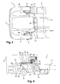
- the hydraulic circuit 10, as illustrated in Figures 1 and 2 can be divided between a static part, connected to the frame, and a mobile part, connected to the wheels.
- the mobile part consists essentially of the hydraulic motors.
- the static part of the hydraulic circuit comprises a pump 11 which can be directly actuated by the vehicle engine - i.e. without any clutch mechanism - and which is preferably a variable displacement pump.
- Said pump 11 is designed to suck the fluid from a tank 12 by a suction line 13 and is capable of delivering the fluid under a maximum pressure of 420 bar, which can be used in particular when starting the vehicle 1, and under an average operating pressure of around 200 bar.
- the high pressure fluid then flows in lines 14, 15 towards a hydraulic valve block 16 which controls the fluid flow in the hydraulic circuit 10.
- the valve block 16 can make the fluid delivered by the pump 11 flow back to said pump 11 via line 17. Thus, the fluid moves in a closed loop and does not flow to the hydraulic motors 8, and therefore does not actuate them.
- the valve block 16 can also be controlled by the vehicle driver and/or by an electronic system to direct the high pressure fluid towards a hydraulic distribution block 18 via lines 19, 20.
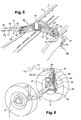
- the hydraulic distribution block 18 is located above the vehicle frame 2, substantially in the median longitudinal plane of the vehicle 1. Moreover, said hydraulic distribution block 18 is located rearwards from the axle 7 of the driving and steering wheels 4, for example close to the rear wall of the cab 6, on a transverse beam or cross-member 48 (see Figure 5 ).
- the hydraulic distribution block is a mere passive flow divider which divides the flow coming from the valve block 16 in two equal parts for each of the hydraulic motors.
- the hydraulic block could be an active component, for example a controlled flow divider regulating the amount of flow sent to each motor, thereby acting as an active differential.
- the hydraulic circuit could exhibit a single hydraulic block combining the functions of the valve block 16 and of the distribution block 18.
- the rear parts of said lines 19, 20, which are close to the valve block 16, can consist of flexible hoses, whereas the front parts of said lines 19, 20, which are close to the hydraulic distribution block 18, are preferably made of rigid pipes, as better shown in Figure 4 and 5 .
- the industrialization of the hydraulic circuit 10 is made easier.
- the hydraulic circuit 10 may further comprise a filtering loop which carries the fluid from the pump 11 to a filter 21 via a line 22 and then back to the pump 11 via a line 23.
- a dedicated drain line 24 is also provided to carry any excess fluid from the filter 21 to the valve block 16.
- the hydraulic circuit 10 may further comprise a cooling loop including a fan 25.
- the fluid is carried from the pump 11 towards the fan 25 via line 26, and then back to the tank 12 via line 27.
- a combined cooling and filtering loop could be provided.
- drain lines are also provided: a drain line 28 extending from the valve block 16 towards the tank 12; a drain line 29 extending from the hydraulic distribution block 18 towards the tank 12; a drain line 30 extending from the hydraulic distribution block 18 towards the valve block 16.
- the high pressure fluid delivered by the pump 11 and flowing from the valve block 16 in lines 19, 20 enters the hydraulic distribution block 18 and is directed towards the hydraulic motor 8 of each of the front wheels 4 by two main lines 31, 32.
- a first main line 31 is used as a supply line for moving the vehicle 1 forwards, the second main line 32 then being the return line towards the hydraulic distribution block 18.
- the second main line 32 is used as a supply line for moving the vehicle 1 backwards, the first main line 31 being the return line.
- Each main line 31, 32 comprises a first rigid pipe 35 extending from a port of the hydraulic distribution block 18, a second rigid pipe 36 extending from a port of the corresponding hydraulic motor 8, and a flexible hose 37 connecting the first and second rigid pipes 35, 36.
- the port of the hydraulic motor 8 can for example be fitted directly on the motor's stator or to any part being in a fixed relationship therewith, such as the steering knuckle, with then the possibility of a further communication channel between the motor and the port.
- the part of the hydraulic circuit 10 including the hydraulic distribution block 18, the hydraulic motors 8 and the connecting lines between them is substantially symmetrical with respect to the median longitudinal plane of the vehicle 1.
- the first rigid pipe 35 has a first portion 40 which extends from the hydraulic distribution block 18 substantially transversely and also slightly downwards, followed by a second portion 41 which forms the free end portion of said pipe 35.
- the second portion 41 defines a first axis, which can be its own axis if the end portion is tubular, but which is more precisely the orientation that this rigid end portion will define for the connecting portions of the flexible hose.
- the second portion 41 can be oriented somewhat forwards, towards the corresponding wheel 4.
- the second rigid pipe 36 has a first portion 42 extending from the corresponding port of the hydraulic motor 8, which is for example located on a lower front part of the hydraulic motor 8.
- Said first portion 42 is bent and includes a part 43 extending downwards and forward from the hydraulic motor 8, followed by an intermediate part 44 extending upwards and rearward, and then a part 45 extending substantially vertically up.
- the vertical parts 45 of both rigid pipes 36 of a same wheel 4 can be housed and maintained in a support 47 fastened onto the hydraulic motor's stator and/or on the steering knuckle.
- the second rigid pipe 36 further comprises a second portion 46 which forms the free end portion of said pipe.
- the second portion 46 of each pipe has an orientation, defined by its axis or by the axis of the flexible hose portion which is connected to it.
- this axis of the second portion 46 of the second rigid pipe 36, and the axis of the second portion 41 of the first rigid pipe 35 are arranged so as to define an operating plane P1 (for the first main line 31), P2 (for the second main line 32).
- P1 for the first main line 31
- P2 for the second main line 32
- the hose 37 will naturally tend, when connected to both end portions, to adopt a shape which lies within the corresponding operating plane, rather than extending along a three-dimensional path as if the end portions has any orientation one with respect to the other.
- the axis of the two end portions need to intersect each other.
- the operating plane is perpendicular or at least substantially perpendicular to the steering axis, meaning that both end portions are oriented substantially perpendicularly to the steering axis of the wheel.
- the orientation of these end portions remain in the same operating plane whatever the steering position of the wheel, and the flexible hose will thus deform itself within said plane, without enduring any substantial twisting around its own axis.
- the second portion 46 is directed rearwards, somewhat towards the second portion 41 of the corresponding first rigid pipe 35.
- the second portions 41, 46 of the first and second rigid pipes 35, 36 of the first main line 31 are located in a first operating plane P1
- the second portions 41, 46 of the first and second rigid pipes 35, 36 of the second main line 32 are located in a second operating plane P2.
- Planes P1 and P2 are distinct and substantially parallel (see in particular Figure 4 ). Both planes P1, P2 are vertically offset and are preferably located above the frame 2, more particularly above the girders 3.
- the operating planes P1 and P2 are substantially horizontal.
- the flexible hose 37 of a main line 31 or 32 is also substantially located in a same horizontal operating plane P1 or P2.
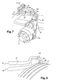
- the flexible hose 37 can be curved as a C (see Figure 7 ) or have an S shape presenting a point of inflexion (see Figure 8 ).
- the drain lines 33, 34 which connect each hydraulic motor 8 to the hydraulic distribution block 18 are flexible and are attached to the flexible hose 37 of one main line 31, 32, typically by means of collars 50.
- This arrangement is advantageous, because since said drain lines 33, 34 carry a fluid having a low pressure (generally in the range of about 10-30 bar), they can be made of a standard flexible which is widely used and not expensive. But at the same time, by attaching said flexible drain lines 33, 34 to a flexible hose 37 whose deformation is controlled thanks to the dispositions of the invention, the path and therefore the deformation of the flexible drain lines 33, 34 are also controlled.
- the drain lines 24, 28, 29, 30 can be flexible since the fluid flowing in said lines has a low pressure.
- the portions of the lines that are entering or going out of the hydraulic distribution block 18 are preferably made of rigid pipes, whether they carry high pressure fluid or low pressure fluid (drain lines). As illustrated in Figures 2 and 5 , these lines include the four first rigid pipes 35 of the main lines 31, 32, the lines 19, 20 connected to the valve block 16, and the drain line 30 also connected to the valve block 16.
- the hydraulic distribution block 18 and most of the lines connected to it form a rigid element whose assembly process can more easily be industrialized, and which can later be mounted more quickly onto the vehicle frame 2.
Landscapes
- Engineering & Computer Science (AREA)
- Chemical & Material Sciences (AREA)
- Combustion & Propulsion (AREA)
- Transportation (AREA)
- Mechanical Engineering (AREA)
- Body Structure For Vehicles (AREA)
Claims (9)
- Fahrzeug mit- einem Rahmen (2),- wenigstens zwei Antriebs- und Lenkrädern (4), die zu einer gleichen Achse (7) gehören, wobei jedes Rad (4) durch einen Hydraulikmotor (8) betätigt wird, der an dem Rad angeordnet ist, und jedes Rad bezüglich des Rahmens um eine Lenkachse verschwenkt wird,- einem Hydraulikkreis (10), der ein Fluid unter Druck führen kann, um die Hydraulikmotoren (8) zu betätigen, wobei der Hydraulikkreis (10) einen statischen Teil (18) umfasst, der an dem Fahrzeugrahmen (2) angebracht ist und der hydraulisch mit jedem der Hydraulikmotoren (8) mittels wenigstens zweier Hauptleitungen (31, 32) verbunden ist,dadurch gekennzeichnet, dass jede Hauptleitung umfasst:- ein erstes steifes Rohr (35), das sich von dem statischen Teil (18) erstreckt und einen entgegengesetzten freien Endabschnitt (41) aufweist,- ein zweites steifes Rohr (36), das sich von einem Kanal des entsprechenden Hydraulikmotors (8) erstreckt und einen entgegengesetzten freien Endabschnitt (46) aufweist,- einen flexiblen Schlauch (37), der die freien Endabschnitte (41, 46) des ersten und zweiten steifen Rohres (35, 36) verbindet,wobei die zwei freien Endabschnitte (41, 46) des ersten und zweiten steifen Rohres (35, 36) derselben Hauptleitung (31, 32) in derselben Funktionsebene (P1, P2) ausgerichtet sind, die im Wesentlichen horizontal und senkrecht zu der Lenkachse verläuft, so dass, wenn die Räder (4) zwischen der extrem linken und rechten Lenkposition bewegt werden, der flexible Schlauch (37) jeder Hauptleitung gebogen wird, wobei er im Wesentlichen in der Funktionsebene (P1, P2) verbleibt.
- Fahrzeug nach Anspruch 1, dadurch gekennzeichnet, dass die Funktionsebene (P1, P2) oberhalb des Fahrzeugrahmens (2) angeordnet ist.
- Fahrzeug nach irgendeinem der Ansprüche 1 oder 2, dadurch gekennzeichnet, dass die freien Endabschnitte (41, 46) des ersten und zweiten steifen Rohrs (35, 36) einer mit einem Rad (4) verbundenen Hauptleitung (31) und die freien Endabschnitte (41, 46) des ersten und zweiten steifen Rohrs (35, 36) der anderen Hauptleitung (32), die mit demselben Rad (4) verbunden ist, zwei Funktionsebenen (P1, P2) bilden, die voneinander unterschiedlich und im Wesentlichen parallel sind.
- Fahrzeug nach irgendeinem der Ansprüche 1 bis 3, dadurch gekennzeichnet, dass der statische Teil des Hydraulikkreises (10) einen Hydraulikverteilungsblock (18) umfasst, der oberhalb des Fahrzeugrahmens (2) in einem Abstand von der Achse (7) der Antriebs- und Lenkräder (4) angeordnet ist, und dass bei wenigstens einer Hauptleitung (31, 32) das erste steife Rohr (35) einen ersten Abschnitt (40), der sich von dem Hydraulikverteilungsblock (18) im Wesentlichen quer erstreckt, und einen zweiten Abschnitt (41) aufweist, der den freien Endabschnitt des Rohrs (35) bildet und der im Wesentlichen horizontal ausgerichtet und in Richtung des entsprechenden Rades (4) gerichtet ist.
- Fahrzeug nach irgendeinem der Ansprüche 1 bis 4, dadurch gekennzeichnet, dass jedes zweite steife Rohr (36) einen ersten Abschnitt (42), der sich von dem entsprechenden Kanal des Hydraulikmotors (8) in Richtung der Funktionsebene (P1, P2) erstreckt, und einen zweiten Abschnitt (46) aufweist, der den freien Endabschnitt des Rohrs (36) bildet und der im Wesentlichen senkrecht zu der Lenkachse des entsprechenden Rads ausgerichtet ist.
- Fahrzeug nach Anspruch 5, dadurch gekennzeichnet, dass der Kanal des Hydraulikmotors (8) an einem unteren Teil des Hydraulikmotors (8) angeordnet ist, wobei der erste Abschnitt (42) des zweiten steifen Rohrs (36) gebogen ist und einen Teil (43), der sich von dem Hydraulikmotor (8) nach unten erstreckt, und einen Teil (45) aufweist, der sich im Wesentlichen vertikal in Richtung des freien Endabschnitts (46) des Rohrs (36) erstreckt.
- Fahrzeug nach irgendeinem der Ansprüche 1 bis 6, dadurch gekennzeichnet, dass der Hydraulikkreis (10) wenigstens eine Ablassleitung (33, 34) umfasst, die jeden Hydraulikmotor (8) des statischen Teils des Hydraulikkreises (10) verbindet, wobei die Ablassleitung (33, 34) flexibel ist und an wenigstens einer der Hauptleitungen (31, 32) angebracht ist, die an den gleichen Hydraulikmotor (8) angeschlossen ist.
- Fahrzeug nach irgendeinem der Ansprüche 1 bis 7, dadurch gekennzeichnet, dass der Hydraulikkreis (10) eine Pumpe (11) umfasst, die das Fluid bewegen kann, wobei die Pumpe (11) eine variable Verdrängungspumpe ist und direkt durch den Fahrzeugmotor ohne irgendeinen Kupplungsmechanismus betätigt wird.
- Fahrzeug nach Anspruch 8, dadurch gekennzeichnet, dass der Hydraulikkreis (10) außerdem ein Ventil (16) umfasst, das so ausgebildet ist, dass es dafür sorgt, dass das von der Pumpe (11) geförderte Fluid sich in einer geschlossenen Schleife bewegt, die nicht die Hydraulikmotoren (8) einschließt, und das zur Richtung des Fluids in Richtung der Hydraulikmotoren (8) gesteuert werden kann.
Applications Claiming Priority (1)
| Application Number | Priority Date | Filing Date | Title |
|---|---|---|---|
| PCT/IB2010/002536 WO2012035368A1 (en) | 2010-09-17 | 2010-09-17 | Vehicle having driving and steering wheels actuated by hydraulic motors |
Publications (2)
| Publication Number | Publication Date |
|---|---|
| EP2616263A1 EP2616263A1 (de) | 2013-07-24 |
| EP2616263B1 true EP2616263B1 (de) | 2014-06-18 |
Family
ID=43971715
Family Applications (1)
| Application Number | Title | Priority Date | Filing Date |
|---|---|---|---|
| EP10770621.0A Active EP2616263B1 (de) | 2010-09-17 | 2010-09-17 | Fahrzeug mit über hydraulikmotoren betätigten antriebs- und steuerrädern |
Country Status (2)
| Country | Link |
|---|---|
| EP (1) | EP2616263B1 (de) |
| WO (1) | WO2012035368A1 (de) |
Families Citing this family (3)
| Publication number | Priority date | Publication date | Assignee | Title |
|---|---|---|---|---|
| DE102012015451A1 (de) * | 2012-08-03 | 2014-02-06 | Man Truck & Bus Ag | Leitungsverlegung für Nutzfahrzeuge |
| US10647197B2 (en) * | 2017-12-21 | 2020-05-12 | Cnh Industrial America Llc | Routing hydrostatic ground drive hoses in a self-propelled agricultural product applicator |
| EP4314124A1 (de) | 2021-03-22 | 2024-02-07 | Versalis S.p.A. | Reaktive polymermischungen, hybride polymerschaumstoffe und herstellungsverfahren dafür |
Family Cites Families (2)
| Publication number | Priority date | Publication date | Assignee | Title |
|---|---|---|---|---|
| DE1922399A1 (de) * | 1969-05-02 | 1970-11-12 | Koedel & Boehm Gmbh | Gelaendegaengiges,insbesondere landwirtschaftliches,selbstfahrendes Fahrzeug mit hydraulischem Antrieb |
| FR2653713A1 (fr) * | 1989-10-27 | 1991-05-03 | Bedel Pierre | Vehicule amphibie pour parcs a huitres. |
-
2010
- 2010-09-17 WO PCT/IB2010/002536 patent/WO2012035368A1/en not_active Ceased
- 2010-09-17 EP EP10770621.0A patent/EP2616263B1/de active Active
Also Published As
| Publication number | Publication date |
|---|---|
| EP2616263A1 (de) | 2013-07-24 |
| WO2012035368A1 (en) | 2012-03-22 |
Similar Documents
| Publication | Publication Date | Title |
|---|---|---|
| CN101765727B (zh) | 互连悬架系统 | |
| US9889882B2 (en) | Dump truck | |
| US9643527B2 (en) | Dump truck | |
| CN101378947A (zh) | 轮悬挂装置 | |
| US20160121721A1 (en) | Working machine | |
| CA2686017A1 (en) | Cab suspension | |
| EP2938530B1 (de) | Zwischenlenkungsarm | |
| US10155543B2 (en) | Dump truck | |
| EP3535145B1 (de) | Auf fahrzeugrahmen montiertes energiegewinnungs- und -abgabesystem | |
| EP2704941B1 (de) | Verfahren zur steuerung einer arbeitsmaschine und arbeitsmaschine | |
| US12545337B2 (en) | Automated compensator for fifth-wheel couplings | |
| US20150352921A1 (en) | Ride height adjustable agricultural vehicle with improved suspension | |
| JP2023535046A (ja) | アクティブサスペンションシステム | |
| JP2023535042A (ja) | アクティブサスペンションシステム | |
| EP3433164A1 (de) | Radladerfronteinheit und radlader | |
| WO2012035368A1 (en) | Vehicle having driving and steering wheels actuated by hydraulic motors | |
| CN106864194B (zh) | 用于从动后轮轴的具有瓦特连杆机构的扭转梁 | |
| CN101096215A (zh) | 汽车,特别是全轮驱动汽车,其具有可转向的第一汽车轴与可转向的第二汽车轴 | |
| EP2519435B1 (de) | Hydraulisches lenksystem zur verwendung in transportfahrzeugen | |
| US7931108B2 (en) | Semi-trailer repositioner | |
| EP2095987A1 (de) | Kraftübertragungsvorrichtung für ein Arbeitsfahrzeug | |
| EP2651746B1 (de) | Servolenksystem für ein fahrzeug mit zwei gesteuerten achsen | |
| CN103802755B (zh) | 用于商用车的管路铺设 | |
| GB2551057A (en) | Chassis for a commercial vehicle, in particular a truck | |
| US11724557B2 (en) | Assembly for a hydraulically suspended vehicle axle |
Legal Events
| Date | Code | Title | Description |
|---|---|---|---|
| PUAI | Public reference made under article 153(3) epc to a published international application that has entered the european phase |
Free format text: ORIGINAL CODE: 0009012 |
|
| 17P | Request for examination filed |
Effective date: 20130131 |
|
| AK | Designated contracting states |
Kind code of ref document: A1 Designated state(s): AL AT BE BG CH CY CZ DE DK EE ES FI FR GB GR HR HU IE IS IT LI LT LU LV MC MK MT NL NO PL PT RO SE SI SK SM TR |
|
| RIN1 | Information on inventor provided before grant (corrected) |
Inventor name: GENTON, DAVID Inventor name: BERNARD, DENIS |
|
| DAX | Request for extension of the european patent (deleted) | ||
| GRAP | Despatch of communication of intention to grant a patent |
Free format text: ORIGINAL CODE: EPIDOSNIGR1 |
|
| INTG | Intention to grant announced |
Effective date: 20140116 |
|
| GRAS | Grant fee paid |
Free format text: ORIGINAL CODE: EPIDOSNIGR3 |
|
| GRAA | (expected) grant |
Free format text: ORIGINAL CODE: 0009210 |
|
| AK | Designated contracting states |
Kind code of ref document: B1 Designated state(s): AL AT BE BG CH CY CZ DE DK EE ES FI FR GB GR HR HU IE IS IT LI LT LU LV MC MK MT NL NO PL PT RO SE SI SK SM TR |
|
| REG | Reference to a national code |
Ref country code: GB Ref legal event code: FG4D |
|
| REG | Reference to a national code |
Ref country code: CH Ref legal event code: EP |
|
| REG | Reference to a national code |
Ref country code: AT Ref legal event code: REF Ref document number: 673124 Country of ref document: AT Kind code of ref document: T Effective date: 20140715 |
|
| REG | Reference to a national code |
Ref country code: IE Ref legal event code: FG4D |
|
| REG | Reference to a national code |
Ref country code: DE Ref legal event code: R096 Ref document number: 602010016825 Country of ref document: DE Effective date: 20140731 |
|
| REG | Reference to a national code |
Ref country code: SE Ref legal event code: TRGR |
|
| PG25 | Lapsed in a contracting state [announced via postgrant information from national office to epo] |
Ref country code: FI Free format text: LAPSE BECAUSE OF FAILURE TO SUBMIT A TRANSLATION OF THE DESCRIPTION OR TO PAY THE FEE WITHIN THE PRESCRIBED TIME-LIMIT Effective date: 20140618 Ref country code: LT Free format text: LAPSE BECAUSE OF FAILURE TO SUBMIT A TRANSLATION OF THE DESCRIPTION OR TO PAY THE FEE WITHIN THE PRESCRIBED TIME-LIMIT Effective date: 20140618 Ref country code: GR Free format text: LAPSE BECAUSE OF FAILURE TO SUBMIT A TRANSLATION OF THE DESCRIPTION OR TO PAY THE FEE WITHIN THE PRESCRIBED TIME-LIMIT Effective date: 20140919 Ref country code: NO Free format text: LAPSE BECAUSE OF FAILURE TO SUBMIT A TRANSLATION OF THE DESCRIPTION OR TO PAY THE FEE WITHIN THE PRESCRIBED TIME-LIMIT Effective date: 20140918 Ref country code: CY Free format text: LAPSE BECAUSE OF FAILURE TO SUBMIT A TRANSLATION OF THE DESCRIPTION OR TO PAY THE FEE WITHIN THE PRESCRIBED TIME-LIMIT Effective date: 20140618 |
|
| REG | Reference to a national code |
Ref country code: NL Ref legal event code: VDEP Effective date: 20140618 |
|
| REG | Reference to a national code |
Ref country code: AT Ref legal event code: MK05 Ref document number: 673124 Country of ref document: AT Kind code of ref document: T Effective date: 20140618 |
|
| REG | Reference to a national code |
Ref country code: LT Ref legal event code: MG4D |
|
| PG25 | Lapsed in a contracting state [announced via postgrant information from national office to epo] |
Ref country code: LV Free format text: LAPSE BECAUSE OF FAILURE TO SUBMIT A TRANSLATION OF THE DESCRIPTION OR TO PAY THE FEE WITHIN THE PRESCRIBED TIME-LIMIT Effective date: 20140618 Ref country code: HR Free format text: LAPSE BECAUSE OF FAILURE TO SUBMIT A TRANSLATION OF THE DESCRIPTION OR TO PAY THE FEE WITHIN THE PRESCRIBED TIME-LIMIT Effective date: 20140618 |
|
| PG25 | Lapsed in a contracting state [announced via postgrant information from national office to epo] |
Ref country code: CZ Free format text: LAPSE BECAUSE OF FAILURE TO SUBMIT A TRANSLATION OF THE DESCRIPTION OR TO PAY THE FEE WITHIN THE PRESCRIBED TIME-LIMIT Effective date: 20140618 Ref country code: ES Free format text: LAPSE BECAUSE OF FAILURE TO SUBMIT A TRANSLATION OF THE DESCRIPTION OR TO PAY THE FEE WITHIN THE PRESCRIBED TIME-LIMIT Effective date: 20140618 Ref country code: EE Free format text: LAPSE BECAUSE OF FAILURE TO SUBMIT A TRANSLATION OF THE DESCRIPTION OR TO PAY THE FEE WITHIN THE PRESCRIBED TIME-LIMIT Effective date: 20140618 Ref country code: PT Free format text: LAPSE BECAUSE OF FAILURE TO SUBMIT A TRANSLATION OF THE DESCRIPTION OR TO PAY THE FEE WITHIN THE PRESCRIBED TIME-LIMIT Effective date: 20141020 Ref country code: RO Free format text: LAPSE BECAUSE OF FAILURE TO SUBMIT A TRANSLATION OF THE DESCRIPTION OR TO PAY THE FEE WITHIN THE PRESCRIBED TIME-LIMIT Effective date: 20140618 Ref country code: SK Free format text: LAPSE BECAUSE OF FAILURE TO SUBMIT A TRANSLATION OF THE DESCRIPTION OR TO PAY THE FEE WITHIN THE PRESCRIBED TIME-LIMIT Effective date: 20140618 |
|
| PG25 | Lapsed in a contracting state [announced via postgrant information from national office to epo] |
Ref country code: AT Free format text: LAPSE BECAUSE OF FAILURE TO SUBMIT A TRANSLATION OF THE DESCRIPTION OR TO PAY THE FEE WITHIN THE PRESCRIBED TIME-LIMIT Effective date: 20140618 Ref country code: NL Free format text: LAPSE BECAUSE OF FAILURE TO SUBMIT A TRANSLATION OF THE DESCRIPTION OR TO PAY THE FEE WITHIN THE PRESCRIBED TIME-LIMIT Effective date: 20140618 Ref country code: IS Free format text: LAPSE BECAUSE OF FAILURE TO SUBMIT A TRANSLATION OF THE DESCRIPTION OR TO PAY THE FEE WITHIN THE PRESCRIBED TIME-LIMIT Effective date: 20141018 Ref country code: PL Free format text: LAPSE BECAUSE OF FAILURE TO SUBMIT A TRANSLATION OF THE DESCRIPTION OR TO PAY THE FEE WITHIN THE PRESCRIBED TIME-LIMIT Effective date: 20140618 |
|
| REG | Reference to a national code |
Ref country code: DE Ref legal event code: R026 Ref document number: 602010016825 Country of ref document: DE |
|
| PLBI | Opposition filed |
Free format text: ORIGINAL CODE: 0009260 |
|
| PLAX | Notice of opposition and request to file observation + time limit sent |
Free format text: ORIGINAL CODE: EPIDOSNOBS2 |
|
| 26 | Opposition filed |
Opponent name: MAN TRUCK & BUS AG Effective date: 20150318 |
|
| PG25 | Lapsed in a contracting state [announced via postgrant information from national office to epo] |
Ref country code: LU Free format text: LAPSE BECAUSE OF FAILURE TO SUBMIT A TRANSLATION OF THE DESCRIPTION OR TO PAY THE FEE WITHIN THE PRESCRIBED TIME-LIMIT Effective date: 20140917 Ref country code: DK Free format text: LAPSE BECAUSE OF FAILURE TO SUBMIT A TRANSLATION OF THE DESCRIPTION OR TO PAY THE FEE WITHIN THE PRESCRIBED TIME-LIMIT Effective date: 20140618 Ref country code: IT Free format text: LAPSE BECAUSE OF FAILURE TO SUBMIT A TRANSLATION OF THE DESCRIPTION OR TO PAY THE FEE WITHIN THE PRESCRIBED TIME-LIMIT Effective date: 20140618 Ref country code: MC Free format text: LAPSE BECAUSE OF FAILURE TO SUBMIT A TRANSLATION OF THE DESCRIPTION OR TO PAY THE FEE WITHIN THE PRESCRIBED TIME-LIMIT Effective date: 20140618 |
|
| REG | Reference to a national code |
Ref country code: CH Ref legal event code: PL |
|
| REG | Reference to a national code |
Ref country code: DE Ref legal event code: R026 Ref document number: 602010016825 Country of ref document: DE Effective date: 20150318 |
|
| REG | Reference to a national code |
Ref country code: IE Ref legal event code: MM4A |
|
| PG25 | Lapsed in a contracting state [announced via postgrant information from national office to epo] |
Ref country code: CH Free format text: LAPSE BECAUSE OF NON-PAYMENT OF DUE FEES Effective date: 20140930 Ref country code: LI Free format text: LAPSE BECAUSE OF NON-PAYMENT OF DUE FEES Effective date: 20140930 Ref country code: SI Free format text: LAPSE BECAUSE OF FAILURE TO SUBMIT A TRANSLATION OF THE DESCRIPTION OR TO PAY THE FEE WITHIN THE PRESCRIBED TIME-LIMIT Effective date: 20140618 |
|
| PLBB | Reply of patent proprietor to notice(s) of opposition received |
Free format text: ORIGINAL CODE: EPIDOSNOBS3 |
|
| PG25 | Lapsed in a contracting state [announced via postgrant information from national office to epo] |
Ref country code: IE Free format text: LAPSE BECAUSE OF NON-PAYMENT OF DUE FEES Effective date: 20140917 |
|
| REG | Reference to a national code |
Ref country code: FR Ref legal event code: PLFP Year of fee payment: 6 |
|
| PG25 | Lapsed in a contracting state [announced via postgrant information from national office to epo] |
Ref country code: SM Free format text: LAPSE BECAUSE OF FAILURE TO SUBMIT A TRANSLATION OF THE DESCRIPTION OR TO PAY THE FEE WITHIN THE PRESCRIBED TIME-LIMIT Effective date: 20140618 |
|
| PG25 | Lapsed in a contracting state [announced via postgrant information from national office to epo] |
Ref country code: BG Free format text: LAPSE BECAUSE OF FAILURE TO SUBMIT A TRANSLATION OF THE DESCRIPTION OR TO PAY THE FEE WITHIN THE PRESCRIBED TIME-LIMIT Effective date: 20140618 Ref country code: MT Free format text: LAPSE BECAUSE OF FAILURE TO SUBMIT A TRANSLATION OF THE DESCRIPTION OR TO PAY THE FEE WITHIN THE PRESCRIBED TIME-LIMIT Effective date: 20140618 |
|
| PG25 | Lapsed in a contracting state [announced via postgrant information from national office to epo] |
Ref country code: BE Free format text: LAPSE BECAUSE OF FAILURE TO SUBMIT A TRANSLATION OF THE DESCRIPTION OR TO PAY THE FEE WITHIN THE PRESCRIBED TIME-LIMIT Effective date: 20140618 Ref country code: HU Free format text: LAPSE BECAUSE OF FAILURE TO SUBMIT A TRANSLATION OF THE DESCRIPTION OR TO PAY THE FEE WITHIN THE PRESCRIBED TIME-LIMIT; INVALID AB INITIO Effective date: 20100917 |
|
| REG | Reference to a national code |
Ref country code: FR Ref legal event code: PLFP Year of fee payment: 7 |
|
| PLCK | Communication despatched that opposition was rejected |
Free format text: ORIGINAL CODE: EPIDOSNREJ1 |
|
| STAA | Information on the status of an ep patent application or granted ep patent |
Free format text: STATUS: THE PATENT HAS BEEN GRANTED |
|
| APBM | Appeal reference recorded |
Free format text: ORIGINAL CODE: EPIDOSNREFNO |
|
| APBP | Date of receipt of notice of appeal recorded |
Free format text: ORIGINAL CODE: EPIDOSNNOA2O |
|
| APAH | Appeal reference modified |
Free format text: ORIGINAL CODE: EPIDOSCREFNO |
|
| APBQ | Date of receipt of statement of grounds of appeal recorded |
Free format text: ORIGINAL CODE: EPIDOSNNOA3O |
|
| PG25 | Lapsed in a contracting state [announced via postgrant information from national office to epo] |
Ref country code: TR Free format text: LAPSE BECAUSE OF FAILURE TO SUBMIT A TRANSLATION OF THE DESCRIPTION OR TO PAY THE FEE WITHIN THE PRESCRIBED TIME-LIMIT Effective date: 20140618 |
|
| REG | Reference to a national code |
Ref country code: FR Ref legal event code: PLFP Year of fee payment: 8 |
|
| PG25 | Lapsed in a contracting state [announced via postgrant information from national office to epo] |
Ref country code: MK Free format text: LAPSE BECAUSE OF FAILURE TO SUBMIT A TRANSLATION OF THE DESCRIPTION OR TO PAY THE FEE WITHIN THE PRESCRIBED TIME-LIMIT Effective date: 20140618 |
|
| REG | Reference to a national code |
Ref country code: FR Ref legal event code: PLFP Year of fee payment: 9 |
|
| PG25 | Lapsed in a contracting state [announced via postgrant information from national office to epo] |
Ref country code: AL Free format text: LAPSE BECAUSE OF FAILURE TO SUBMIT A TRANSLATION OF THE DESCRIPTION OR TO PAY THE FEE WITHIN THE PRESCRIBED TIME-LIMIT Effective date: 20140618 |
|
| REG | Reference to a national code |
Ref country code: DE Ref legal event code: R100 Ref document number: 602010016825 Country of ref document: DE |
|
| APBU | Appeal procedure closed |
Free format text: ORIGINAL CODE: EPIDOSNNOA9O |
|
| PLBN | Opposition rejected |
Free format text: ORIGINAL CODE: 0009273 |
|
| STAA | Information on the status of an ep patent application or granted ep patent |
Free format text: STATUS: OPPOSITION REJECTED |
|
| 27O | Opposition rejected |
Effective date: 20190218 |
|
| PGFP | Annual fee paid to national office [announced via postgrant information from national office to epo] |
Ref country code: DE Payment date: 20250926 Year of fee payment: 16 |
|
| PGFP | Annual fee paid to national office [announced via postgrant information from national office to epo] |
Ref country code: GB Payment date: 20250923 Year of fee payment: 16 |
|
| PGFP | Annual fee paid to national office [announced via postgrant information from national office to epo] |
Ref country code: FR Payment date: 20250925 Year of fee payment: 16 |
|
| PGFP | Annual fee paid to national office [announced via postgrant information from national office to epo] |
Ref country code: SE Payment date: 20250924 Year of fee payment: 16 |