EP2615518A1 - Procédé de mise en temperature et de régulation de la température d'un outil de fabrication chauffé par un fluide en phase liquide et/ou vapeur - Google Patents
Procédé de mise en temperature et de régulation de la température d'un outil de fabrication chauffé par un fluide en phase liquide et/ou vapeur Download PDFInfo
- Publication number
- EP2615518A1 EP2615518A1 EP13151134.7A EP13151134A EP2615518A1 EP 2615518 A1 EP2615518 A1 EP 2615518A1 EP 13151134 A EP13151134 A EP 13151134A EP 2615518 A1 EP2615518 A1 EP 2615518A1
- Authority
- EP
- European Patent Office
- Prior art keywords
- time
- heating
- temperature
- pulse
- control
- Prior art date
- Legal status (The legal status is an assumption and is not a legal conclusion. Google has not performed a legal analysis and makes no representation as to the accuracy of the status listed.)
- Granted
Links
Images


Classifications
-
- G—PHYSICS
- G05—CONTROLLING; REGULATING
- G05D—SYSTEMS FOR CONTROLLING OR REGULATING NON-ELECTRIC VARIABLES
- G05D23/00—Control of temperature
- G05D23/19—Control of temperature characterised by the use of electric means
- G05D23/1917—Control of temperature characterised by the use of electric means using digital means
-
- B—PERFORMING OPERATIONS; TRANSPORTING
- B29—WORKING OF PLASTICS; WORKING OF SUBSTANCES IN A PLASTIC STATE IN GENERAL
- B29C—SHAPING OR JOINING OF PLASTICS; SHAPING OF MATERIAL IN A PLASTIC STATE, NOT OTHERWISE PROVIDED FOR; AFTER-TREATMENT OF THE SHAPED PRODUCTS, e.g. REPAIRING
- B29C35/00—Heating, cooling or curing, e.g. crosslinking or vulcanising; Apparatus therefor
- B29C35/02—Heating or curing, e.g. crosslinking or vulcanizing during moulding, e.g. in a mould
- B29C35/0288—Controlling heating or curing of polymers during moulding, e.g. by measuring temperatures or properties of the polymer and regulating the process
-
- B—PERFORMING OPERATIONS; TRANSPORTING
- B29—WORKING OF PLASTICS; WORKING OF SUBSTANCES IN A PLASTIC STATE IN GENERAL
- B29C—SHAPING OR JOINING OF PLASTICS; SHAPING OF MATERIAL IN A PLASTIC STATE, NOT OTHERWISE PROVIDED FOR; AFTER-TREATMENT OF THE SHAPED PRODUCTS, e.g. REPAIRING
- B29C45/00—Injection moulding, i.e. forcing the required volume of moulding material through a nozzle into a closed mould; Apparatus therefor
- B29C45/17—Component parts, details or accessories; Auxiliary operations
- B29C45/76—Measuring, controlling or regulating
- B29C45/78—Measuring, controlling or regulating of temperature
-
- B—PERFORMING OPERATIONS; TRANSPORTING
- B29—WORKING OF PLASTICS; WORKING OF SUBSTANCES IN A PLASTIC STATE IN GENERAL
- B29C—SHAPING OR JOINING OF PLASTICS; SHAPING OF MATERIAL IN A PLASTIC STATE, NOT OTHERWISE PROVIDED FOR; AFTER-TREATMENT OF THE SHAPED PRODUCTS, e.g. REPAIRING
- B29C35/00—Heating, cooling or curing, e.g. crosslinking or vulcanising; Apparatus therefor
- B29C35/02—Heating or curing, e.g. crosslinking or vulcanizing during moulding, e.g. in a mould
- B29C35/04—Heating or curing, e.g. crosslinking or vulcanizing during moulding, e.g. in a mould using liquids, gas or steam
- B29C35/041—Heating or curing, e.g. crosslinking or vulcanizing during moulding, e.g. in a mould using liquids, gas or steam using liquids
-
- B—PERFORMING OPERATIONS; TRANSPORTING
- B29—WORKING OF PLASTICS; WORKING OF SUBSTANCES IN A PLASTIC STATE IN GENERAL
- B29C—SHAPING OR JOINING OF PLASTICS; SHAPING OF MATERIAL IN A PLASTIC STATE, NOT OTHERWISE PROVIDED FOR; AFTER-TREATMENT OF THE SHAPED PRODUCTS, e.g. REPAIRING
- B29C35/00—Heating, cooling or curing, e.g. crosslinking or vulcanising; Apparatus therefor
- B29C35/02—Heating or curing, e.g. crosslinking or vulcanizing during moulding, e.g. in a mould
- B29C35/04—Heating or curing, e.g. crosslinking or vulcanizing during moulding, e.g. in a mould using liquids, gas or steam
- B29C35/049—Heating or curing, e.g. crosslinking or vulcanizing during moulding, e.g. in a mould using liquids, gas or steam using steam or damp
-
- B—PERFORMING OPERATIONS; TRANSPORTING
- B29—WORKING OF PLASTICS; WORKING OF SUBSTANCES IN A PLASTIC STATE IN GENERAL
- B29K—INDEXING SCHEME ASSOCIATED WITH SUBCLASSES B29B, B29C OR B29D, RELATING TO MOULDING MATERIALS OR TO MATERIALS FOR MOULDS, REINFORCEMENTS, FILLERS OR PREFORMED PARTS, e.g. INSERTS
- B29K2101/00—Use of unspecified macromolecular compounds as moulding material
- B29K2101/10—Thermosetting resins
Definitions
- the invention relates to a method for heating and regulating the temperature of a heated with a liquid and / or vapor heat carrier tool with at least one heating circuit for shaping and / or fixing of moldings made of thermosetting or crosslinkable materials.
- polymer materials are used for the production of molded parts, the processing or shaping process of which is effected by the application of heat.
- Crosslinkable or crosslinkable or thermosetting polymeric materials are used for the production of products or molded parts from duromers or rubber (vulcanized natural or synthetic rubbers).
- thermoforming compositions in which an irreversible crosslinking reaction is triggered in the production process by targeted heat supply, which is a polymerization, polyaddition, polycondensation or vulcanization depending on the chemical structure of the molding composition.
- the temperature control for the required heat supply must be controlled so that during the conversion of the molding material into the moldable state and the shaping still no crosslinking reaction takes place.
- the heat input must be controlled in such a way that a uniformly high degree of crosslinking is achieved with the shortest possible cycle times, combined with a high degree of accuracy of the part during the entire production time of the products.
- shaping and fixing methods for example, injection molding, injection-compression molding or compression molding are suitable, in specific cases, the temperature-controlled shape fixing is also carried out in autoclaves or reaction vessels.
- one or more heating circuits are provided in the tool, through which a suitable heating medium flows.
- the required mold temperature depends on a large number of factors, such as the type of molding compound, the wall thickness of the molding, requirements for shrinkage, distortion and dimensional stability as well as demoulding conditions.
- the use of steam plays a minor role compared to other fluid heating media. In the rubber industry, for example, steam is used to heat presses for the vulcanization of tires.
- the disadvantage of steam for heating tools that require a constant tool temperature the high control engineering effort, since steam is not a constant volume flow, as is the case for example with water or oil as the heating medium. When used saturated steam has to be taken into consideration that condensate is produced in the steam discharge, which must be removed.
- the present invention preferably relates to such process operations which require continuous heating by means of steam, in particular saturated steam, but is not limited to this heat carrier, but is also suitable for processes in which water or oil is used as the heat carrier.
- the heating medium in the tool flows through at least one channel as a heating circuit with supply and return, thereby delivering the required heat to the molding compound in order to allow it to be shaped and cured and / or crosslinked.
- the invention has for its object to provide a method for heating and regulating the temperature of a heated with a liquid or vapor heat transfer tool with at least one heating circuit for shaping and / or fixation of moldings made of thermosetting or crosslinkable materials, at least during the stationary heating period an exact adjustment of the actual tool temperature to the required setpoint temperature allows.
- a heating circuit-specific heating profile is stored in the memory of the control and regulation unit as the basis for the regulation of the mold temperature. This is prepared in advance on the basis of existing experience and knowledge from practical operation for shaping and / or fixing of molded parts made of thermosetting or crosslinkable materials.
- the heating and control process is divided into at least two periods, a heating-up period with at least one heating phase and at least one Einschwenkphase and a stationary heating period with different control behavior.
- the heat transfer medium for example, steam, water or oil
- the heating circuit supplied supplied.
- the corresponding medium can be used alternately, both in the liquid and in the vapor state.
- the actual temperature at the tool is measured directly at the point of entry of the heat transfer medium into the tool.
- the supply of the heat transfer medium in the heating period is timed interrupted in dependence on the target / actual temperature comparison, such that heat transfer media pulses of different duration are formed with, if necessary, timed complete interruptions of the supply of heat transfer medium as pause times.
- the term pulse length is also used in connection with media pulses.
- the time- and / or temperature-dependent changes are made by controlling the supply amount of heat transfer medium via an operable in an "open” and “closed” position valve, the actuation of the valve is carried out via a predetermined control algorithm.
- a manufacturing period joins the heating period, e.g. during injection molding, transfer molding or compression molding
- the regulation of the temperature in the tool is carried out during the manufacturing period at least in an analogous manner as during the heating period.
- the heating profile may comprise at least one heating module with heating times as a function of the predetermined setpoint temperature and heat-cycle-specific heating characteristics, a first and a second swivel module with values for swivel duration as a function of the setpoint temperature and the heating characteristics, and a pulse time module with setpoint impulse times for the heat carrier supply as a function of Set temperature and the heating characteristics are formed.
- the individual modules are assigned to a specific temperature of the heat carrier and prior to the start of heating, a heat-up specific heating characteristic is selected.
- the heating profiles are created with reference to the heating medium used.
- the heating phase defined by continuous heat carrier supply is ended, assuming that an actual temperature allocated from the heating profile at a predetermined heating characteristic is below the set temperature by a specific amount of 2 to 10% of the setpoint temperature.
- time-degressive shortening heat transfer pulses are introduced in time to bring the actual temperature metered to the target temperature, the first comparison of the actual temperature with the target temperature to Beginning of the last time module of this Einschwenkphase is made.
- the heat transfer pulse duration of the last time module of the first Einschwenkphase is made .
- a second comparison of the setpoint / actual temperature is performed, wherein in case of deviations within a tolerance range of the transition to the stationary heating period, and for deviations that are outside the tolerance range, further corrections are introduced control technology.
- the mean value of the temperature which is determined from the beginning of the respective heat transfer pulse over a measuring time of 40 to 90%, preferably 75%, of the pulse length to be triggered, and depending on the measured temperature difference between the average value of the actual temperature and the target temperature
- a correction value is determined via which after the measuring time the further duration of the current heat transfer pulse is shortened or extended.
- the correction value for shortening or lengthening the current heat transfer pulse is determined according to the calculation formula (4).
- a "sliding" adjustment of the setpoint pulse length is made for all follow-up pulses after the first heat transfer pulse has been initiated, if the deviations between the actual and setpoint temperatures amount to at least 0.5 ° K and the sign of the currently determined temperature deviation is in a determined number of immediately preceding Temperiermedienimpulse determined deviations, wherein a new desired pulse duration according to the calculation formula (5) is determined.
- the production period initiated when a predetermined tolerance value of a control deviation was undershot at least once during the comparison of setpoint / actual temperature in the stationary heating period.
- the supply of the heat transfer medium is synchronized during the production period with the time for triggering a signal from the sequence control of the production machine.
- the control is maintained according to the stationary heating period, the initiation of a heat transfer pulse is triggered by the signal from the sequence control of the production machine and control technology, the initiation and timing of heat transfer pulses at the time of the cycle-synchronous signal triggering and the duration of the manufacturing cycle are adjusted ,
- the cycle time can be predetermined or it is determined from the time between two identical signals of adjacent cycles from the sequence control of the processing machine.
- the setpoint pulse time of the cycle-modulated production period is calculated according to equation (8).
- the setpoint pulse is triggered when the signal from the machine sequence control starts.
- an adjustment of the heat transfer pulse duration according to equation (9) is made in the subsequent cycle.
- the system automatically switches back to time-modulated control.
- a cycle-time-modulated control can first be carried out and, after a defined period of time until the end of the cycle, automatically switched over to time-modulated control.
- the time duration of the time module is predetermined in this case as a function of the cycle duration.
- the cycle times can be shortened and the quality of the molded parts improved by means of the procedure according to the invention.
- the reject rate is reduced.
- the molded part "light carrier" made of hot-hardening UP-molding compound is produced by injection-compression molding.
- Heating medium Steam, flow temperature 180 ° C Cycle time: 65 sec Time module (ZM): 60 sec.
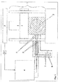
- FIG. 1 the closing unit 1 of the injection molding machine used for injection-compression molding is shown in a simplified representation, wherein the two-part injection-compression molding tool 2 is attached to the clamping plates of the injection molding machine.
- the flow control unit 3 for the injection molding machine and the control unit 4 for regulating the temperature of the steam-heated injection compression tool 2 are shown as block diagrams.
- the control unit is connected to a computer, not shown in detail, for example, computer, on which the required software for performing arithmetic operations and control and control operations is installed.
- the injection compression tool 2 is equipped with four separately controllable heating circuits, of which in the Fig. 1 in each case the flow and return lines 7, 8 for the steam supply (indicated by arrows) of the two front heating circuits can be seen.
- an electrically actuated solenoid valve 5 is incorporated for opening and closing the steam supply.
- Each heating circuit is located in the steam supply line 7 directly at the entrance to the tool 2 via a short metal connection to the tool integrated temperature sensor 6, which is connected to the control unit 4.
- the control unit 4 is coupled to the flow control unit 3 for the injection molding machine via the line S1 to supply a signal from the flow control of the injection molding machine to the control unit 4.
- For the control of the tool temperature only a single signal from the machine sequence control is required, such as "closing the tool time".
- the process sequence for heating the injection-compression molding tool 2 is subdivided into three periods, a first period for heating the injection-compression molding tool to operating temperature (heating period), a second period for further control of the heating of the tool for maintaining the stationary heating state (stationary heating period) and as a third period, the production period, the actual injection molding of the moldings.
- the heating-up period is only required if the tool is used for the first time or is put back into service again after an interruption in production. In the case of short-term faults during operation, re-heating is not required.
- the stationary heating period begins when at the end of a Einschwenkphase the setpoint / Isttemperatur13 for the respective heating circuit results in a deviation less plus / minus 5 ° K.
- control and regulation unit also includes an input unit, a signal input, signal processing and signal output unit, as well as a display unit and memory unit.
- Setpoint temperatures, as so-called pulse time module IZM are recorded as a database on the memory either in graphical and / or tabular form, based on a very specific steam temperature (in this case: 180 ° C.).
- the numerical values available for this purpose form the basis for the arithmetic operations which automatically take place during operation for the purpose of determining the control behavior, whereby the entire practically possible thermal behavior of tool cycles is recorded by the stored modules.
- the Einschwenkmodul comprises one or more Einschwenkphasen, the duration of which are calculated differently, with possibly also several Einschwenkphasen can be introduced in a row.
- the category of the heating character for a heating circuit to be used in the respective application is generally determined by the operator on the basis of empirical values and may optionally automatically skip to another category during the control process if the first input proves to be too inaccurate.
- the heating module includes the work field in terms of the relationship between steam temperature, heating time and set temperature. The mathematical relationship of these basic relationships is based, for example, on an exponential function, the heating character being determined by the magnitude of the exponent.
- the Einschwenkmodul EM (see Tables 2 and 3) includes the working field in terms of the relationship between Einschwenkdauer, Aufmake character and target temperature, based on a specific form of a potential function with reciprocal exponent or on a logarithmic relationship.
- the pulse time module IZM (see Fig. 3 and Table 4) includes the working field in terms of the relationship between Aufbest character, set temperature and target pulse time, assuming a steady-state operation. Tables 1 to 4 are given at the end of the description.
- the pulse time module is based on a specific form of a potential function, the setpoint temperature and the heating character being variables. The calculation can also be made according to a logarithmic relationship.
- the controlled variable of the method is a temperature whose measuring location is arranged close to the point of entry of the steam into the tool and at the same time also permits thermal information about the peripheral temperature state of the tool via a short, metallic connecting piece with integrated temperature sensor.
- the temperature at this measuring location the closer the temperature state of the tool during heating to the steady state approaching, increasingly adapted to the temperature state, which is measured in the geometric center of a heating circuit in the tool.
- the measuring point temperature is then, depending on the thermal and geometric conditions, always between 2 to 5 ° K above the mean mold temperature and indicates changes in the average mold temperature state, although delayed, but safe.
- the control technology use of this temperature signal is thus consuming, but the advantage of the measuring arrangement that no probes with special effort in the tool per circle placed, maintained and possibly repaired, speaks for the much higher procedural ease of use of this solution.
- the manipulated variable of the method is the duration of the steam volume flow, which is controlled by means of appropriate actuators, e.g. Solenoid valves or engine control valves, time-modulated via the respective flow line is supplied.
- actuators e.g. Solenoid valves or engine control valves
- a condensate drain valve is integrated, via which condensate is removed.
- a target temperature of 165 ° C and for the two heating circuits III and IV of the drive side a target temperature of 155 ° C are given for the two heating circuits I and II of the nozzle side of the tool.
- the heating period begins, wherein the solenoid valves 5 are opened and 100% of the available steam volume flow through the channels of the heating circuits I to IV flow.
- the tool should be closed to avoid unnecessary heat loss.
- the continuous steam supply in the heating-up period is terminated when, according to the heating module (see Fig. 2 and Table 1) an actual temperature would have to be reached, which is a certain amount X (5, 10 or 15 ° C), below the target temperature.
- a certain amount X 5, 10 or 15 ° C
- Each heating character is assigned a certain amount X, as indicated below, the values being stored in the working memory as part of the heating profile: Aufiller character very fast fast normal slowly sluggish Amount X ° K 15 10 10 10 5
- the first Einschwenkphase ⁇ 1 is characterized by a minute modulated decreasing shortening steam pulse mode.
- the duration of the Einschwenkphase depends on the chosen Aufmake character and the height of the desired set temperature. It is automatically generated from the first swivel module stored in the memory of the control unit (see Table 2). Based on the present example results for the two circuits of the nozzle side a Einschwenkdauer ⁇ 1 of 18 minutes and for the circuits of the nozzle side of 20 min.
- the desired pulse duration t soll is important.
- the setpoint pulse duration t soll is identical to the pulse duration which is required for minute-modulated steam pulse operation in order to maintain the stationary operating state at the constant high level in the stationary operating state at a specific setpoint temperature and the specific heating characteristic To maintain temperature level exactly.
- This desired pulse duration t soll is also dependent on the heating character of the respective heating circuit and the height of the desired setpoint temperature. It is also generated from the "pulse time module IZM" stored in the memory of the control unit.
- the following table shows the initial values and the adjustments made or changes in the setpoint pulse duration within the last minute of the first switch-on duration: heating circuits I II III IV Target temperature ° C 165 165 155 155 Desired pulse duration s / min 15.4 15.4 21.1 21.1 Actual temperature at the beginning of the last minute ° C 156 175 129 173 Adjustment of the set pulse duration in the last minute to s / min 30.8 0 42.2 0
- Heating circuit I (at 7 ° C too low actual temperature):
- a reheating time in minutes is automatically determined and triggered, the duration of which is derived in such a way that the difference between the heating time at the selected set temperature and the heating time at the measured actual temperature formed and with a damping factor between 0.5 and 0, 9 is multiplied.
- Heating circuit 11 (actual temperature too high by 7 ° C):
- a heat break is first set, ie the steam supply is interrupted.
- the duration of the required break or break is automatically determined from the heat-up module (category "fast") as follows: Actual temperature: 172 ° C Heating time: 35.9 min set temperature 165 ° C heating up 28.4 min Difference: 7,5 min
- the swelling duration which is characterized progressively per minute with increasing pulses, was determined to be 10 min.
- Heating circuit III (actual temperature 24 ° C too low):
- Table 1 gives the following values: For t A is given at 131 ° C: 76.90 min For t A, the result is 155 ° C: 120.70 min
- Heating circuit IV (actual temperature too high by 16 ° C):
- t A lazy is the heating time at setpoint temperature according to the originally selected category "sluggish” t A normal is the heating time at setpoint temperature according to the newly selected category ° C "normal” t A slow (at 155 °): 83.5 min t A normal (155 ° C): 50.1 min
- t soll the time is selected from the pulse time module, which results at setpoint temperature for the newly selected category "normal". t should (at 155 ° C): 15,9s
- the duration is automatically determined and triggered by the installed calculation software.
- the regulation of the temperature of the individual heating circuits I to IV takes place after completion of the respective heating phase by introducing time-modulated intermittent steam pulses (steam temperature 180 ° C).
- 1 minute was chosen as the time unit, that is to say that a steam pulse exactly predetermined in time is triggered per minute so that the temperature at the measuring location is kept at the desired setpoint temperature level.
- control is always the average value of the temperature, which is measured from the beginning of a heat pulse over 40 to 90%, preferably 75%, of the pulse length to be triggered, used.
- measuring time is used. This ensures that in terms of control technology thermodynamic disturbances in the same control cycle both pulse time extensions and pulse time reductions of up to 25% of the current steam pulse can be made.
- the correction factor K is calculated by means of special mathematical relationships as a function of the respectively measured temperature difference ⁇ and the corrected pulse length resulting from the difference form and negative temperature difference from the summation form of equation (4) in the current minute in the same way made effective that the pulse time compared to the desired pulse time is shortened or extended.
- the regulation is explained in detail below for the individual heating circuits I to IV.
- the control for the stationary operating period begins immediately after the end of the heating period for the relevant heating circuit, ie when the Einschwenkphase ended and the deviations from the predetermined setpoint temperature less than plus / minus 5 ° K are.
- the measured actual temperature at the end of the swivel phase is 163.5 ° C.
- a temperature of 163.5 ° C. is measured at the beginning of the pulse (time t o ) and a temperature of 165.3 ° C. at the time t (75) .
- a temperature of 166.5 ° C. is measured at the start of the pulse (time t o ) and a temperature of 168.5 ° C. at the time t (75) .
- the third steam pulse is now re- triggered with the newly calculated value t soll , over a period of 14.98 s.
- the temperature measurement immediately after completion of this steam pulse duration was below the target temperature by 0.4 ° K, so that no further correction of the steam pulse duration is required.
- the method for "sliding" adjustment of the setpoint pulse length also has the goal of determining the pulse length at which the setpoint temperature is maintained exactly during stationary operation without continuous pulse time corrections.
- heating character thermal heating circuit characteristic
- setpoint temperature this is always only a concrete point, which lies only coincidentally on the line of the selected Aufmai characters.
- the knowledge of this operating point is important because the mathematically described characteristics of the operating point, i. the coordinates in the working field, when restarting a process, combined with a new heating phase, pivoting u. a. the effective control behavior sets faster. Therefore, the coordinates of the thermal operating point, from which also the thermal characteristic behavior of the respective heating circuit can be derived, stored after the first determination in the memory of the control unit zugriffpoint.
- the minute-modulated intermittent control phase for the stationary operating period is initiated after completion of the second Einschwenkphase.
- the setpoint pulse time t setpoint is 26.4 s / min (heating character "sluggish").
- a temperature of 153 ° C. was measured at time t o and 154.6 ° C. at time t 75 . This results in a mean value of 153.8 ° C and thus a ⁇ of -1.2 ° K.
- the temperature difference setpoint-actual set to a ⁇ ⁇ of +0.6 ° K in the second minute.
- the control system indicates to the operator via the signal "ready for operation" that the production process of the molded parts can be started.
- thermosetting molding compound is injected at a temperature of 80 ° C in the two mold cavities of the slightly open tool (each 1350 g). Thereafter, the tool is closed, wherein the dipping edge closes the cavity before the end of the closing stroke, so that only volatile fission products can escape and no material can escape.
- the curing or curing process begins, wherein optimal conditions are achieved when the predetermined set temperatures 165 ° C and 155 ° C for the heating circuits I to IV are maintained during the injection cycles during the entire operating period.
- the control of the mold temperature is always carried out according to the same control mechanism as in the stationary heating period
- a time-adjustable delay time from the signal S 1 "close tool" for triggering the steam pulse is provided as selectable in the control unit ,
- the value 0 has been selected as the delay time, that is, the delay time.
- the first steam pulse is triggered synchronously with the signal S1, "close tool", for all heating circuits I to IV.
- Variant A control with fixed time module (in the example, one minute was selected as the time module)
- the measuring time t o to t 75 begins with the initiation of the steam pulse which occurs before the tool closes (before S1) and ends after a period of 75% of the setpoint pulse duration.
- the mean value of the temperatures measured over this period t o to t 75 is used as intended for the calculation of the corrected setpoint pulse duration according to equation (4). Any necessary correction of t want but made to the pulse length, which starts from S1. t to in the preceding equation is always calculated in the preceding control cycle corrected to t -time.
- the obligatory setpoint pulse is initiated at this time S1.
- the new extended pause time is calculated from the remainder of the old aborted extended pause plus new set pause, which is derived from the impulse length of the current impulse.
- Variant B With cycle-time-modulated control
- the cycle time for minute-modulated process conditions is first determined by measuring the time between the signals S 1 of adjacent injection cycles, taking into account one or more injection cycles.
- the fixed specification of the cycle time by the machine operator is possible.
- the cycle-time-modulated setpoint pulse t z soll is also triggered at the beginning of the signal S 1.
- This mode has the advantage that the entire amount of heat required in the cycle to maintain the desired temperature level of the tool is introduced at the beginning of the cycle. This results in the advantages for the possible shortening of the cycle time (hardening time) and the flow-technically more favorable conditions during the molding process compared to conventional heating methods.
- the tool temperature control takes place in cycle time modulated driving mode analogous to the minute modulated.
- cycle-time-modulated control there is the danger of possible fluctuations of the cycle time, caused for example by by different lengths of machine movement times, spontaneously performed operator actions u. a.
- thermodynamic disturbances are detected and corrected in the same cycle.
- Particularly advantageous is the exact metered introduction of all or most of the heat required per cycle at the beginning of the cycle.
- the molding process can take place at higher tool contour temperatures. The result is a better, more faithful flow out of the molding compound in the shaping and the resulting reduction of technologically caused rejects.
- the higher energy input into the tool at the beginning of the cycle results in a possible reduction of the cycle time by 5 to 15%.
- the heating and control of the mold temperature for the production of the light carrier according to the example shown made possible a stable quality-compliant production while maintaining a cycle time of 65 s.
- a shortening of the cycle time leads as a side effect to heating cost savings for the provision of steam.
- productivity can be increased by up to 15% and scrap rates reduced by up to 30%.
Applications Claiming Priority (1)
| Application Number | Priority Date | Filing Date | Title |
|---|---|---|---|
| DE201210100327 DE102012100327A1 (de) | 2012-01-16 | 2012-01-16 | Verfahren zur Aufheizung und Regelung der Temperatur eines mit einem flüssigen oder dampfförmigen Wärmeträger beheizten Werkzeuges |
Publications (2)
| Publication Number | Publication Date |
|---|---|
| EP2615518A1 true EP2615518A1 (fr) | 2013-07-17 |
| EP2615518B1 EP2615518B1 (fr) | 2017-03-29 |
Family
ID=47559287
Family Applications (1)
| Application Number | Title | Priority Date | Filing Date |
|---|---|---|---|
| EP13151134.7A Not-in-force EP2615518B1 (fr) | 2012-01-16 | 2013-01-14 | Procédé de mise en temperature et de régulation de la température d'un outil de fabrication chauffé par un fluide en phase liquide et/ou vapeur |
Country Status (4)
| Country | Link |
|---|---|
| EP (1) | EP2615518B1 (fr) |
| DE (1) | DE102012100327A1 (fr) |
| ES (1) | ES2628342T3 (fr) |
| PL (1) | PL2615518T3 (fr) |
Cited By (1)
| Publication number | Priority date | Publication date | Assignee | Title |
|---|---|---|---|---|
| CN107584738A (zh) * | 2017-09-13 | 2018-01-16 | 安徽安缆模具有限公司 | 一种注塑模具智能化温度控制系统 |
Citations (3)
| Publication number | Priority date | Publication date | Assignee | Title |
|---|---|---|---|---|
| US3735805A (en) * | 1967-09-15 | 1973-05-29 | Buller Ag Geb | Method and apparatus for the temperature control of molding machines |
| DE4141996A1 (de) | 1991-12-19 | 1993-06-24 | Bosch Gmbh Robert | Verfahren zur ueberwachung und/oder regelung eines formgebungsprozesses fuer vernetzende formmaterialien |
| DE4307347A1 (de) * | 1993-03-09 | 1994-09-22 | Werner Kotzab | Verfahren zum Temperieren einer Spritzgießform |
Family Cites Families (1)
| Publication number | Priority date | Publication date | Assignee | Title |
|---|---|---|---|---|
| CZ289862B6 (cs) * | 1994-09-27 | 2002-04-17 | Erich Dr. Liehr | Způsob temperování jednotek vstřikovacích licích strojů, zejména pro zpracování zesítitelných polymerů, a jednotek tvarovacích nástrojů pro zpracování plastů |
-
2012
- 2012-01-16 DE DE201210100327 patent/DE102012100327A1/de not_active Withdrawn
-
2013
- 2013-01-14 PL PL13151134T patent/PL2615518T3/pl unknown
- 2013-01-14 EP EP13151134.7A patent/EP2615518B1/fr not_active Not-in-force
- 2013-01-14 ES ES13151134.7T patent/ES2628342T3/es active Active
Patent Citations (3)
| Publication number | Priority date | Publication date | Assignee | Title |
|---|---|---|---|---|
| US3735805A (en) * | 1967-09-15 | 1973-05-29 | Buller Ag Geb | Method and apparatus for the temperature control of molding machines |
| DE4141996A1 (de) | 1991-12-19 | 1993-06-24 | Bosch Gmbh Robert | Verfahren zur ueberwachung und/oder regelung eines formgebungsprozesses fuer vernetzende formmaterialien |
| DE4307347A1 (de) * | 1993-03-09 | 1994-09-22 | Werner Kotzab | Verfahren zum Temperieren einer Spritzgießform |
Non-Patent Citations (1)
| Title |
|---|
| KOTZAB W: "EXAKTE TEMPERIERUNG BEI GERINGEM KOSTENAUFWAND", PLASTVERARBEITER, HUETHIG GMBH, HEIDELBERG, DE, vol. 35, no. 5, 31 May 1984 (1984-05-31), pages 74 - 81, XP001172778, ISSN: 0032-1338 * |
Cited By (1)
| Publication number | Priority date | Publication date | Assignee | Title |
|---|---|---|---|---|
| CN107584738A (zh) * | 2017-09-13 | 2018-01-16 | 安徽安缆模具有限公司 | 一种注塑模具智能化温度控制系统 |
Also Published As
| Publication number | Publication date |
|---|---|
| EP2615518B1 (fr) | 2017-03-29 |
| PL2615518T3 (pl) | 2017-09-29 |
| ES2628342T3 (es) | 2017-08-02 |
| DE102012100327A1 (de) | 2013-07-18 |
Similar Documents
| Publication | Publication Date | Title |
|---|---|---|
| EP3661720B1 (fr) | Procédé de thermorégulation variothermique d'outils de moulage par injection | |
| EP2583811B2 (fr) | Procédé de quantification de basculements de procédés dans le cadre d'un processus d'injection d'une machine de moulage par injection | |
| EP1372934A1 (fr) | Procede d'equilibrage automatique du remplissage volumetrique de cavites | |
| DE4309880C2 (de) | Verfahren und Anlage zur Temperierung von Formwerkzeugen für die Kunststoffverarbeitung | |
| DE102015114845B4 (de) | Verfahren und Gerät zum Spritzgießen von Kunststoffmaterialien | |
| DD285570A5 (de) | Spritzgussverfahren und spritzgussvorrichtung | |
| EP0704293B1 (fr) | Procédé de régulation en température d'unités d'injection et de moules d'injection de matières plastiques | |
| DE102009046835A1 (de) | Spritzgießwerkzeug | |
| DE102004031546A1 (de) | Verfahren zum Füllen von zumindest einer Kavität | |
| WO2002076704A1 (fr) | Procede pour la regulation du retrait de pieces moulees par injection | |
| DE102016101523A1 (de) | System und Verfahren zum Spritzgießen von Kunststoffen | |
| EP2615518B1 (fr) | Procédé de mise en temperature et de régulation de la température d'un outil de fabrication chauffé par un fluide en phase liquide et/ou vapeur | |
| EP2473339B1 (fr) | Procede de vulcanisation de pneumatiques du vehicule dans une presse chauffee | |
| DE102010022508B4 (de) | Verfahren zum Herstellen eines Faserverbundbauteils | |
| DE2425621A1 (de) | Spritzgiessmaschine | |
| DE4436117A1 (de) | Verfahren zur Temperierung von Spritzgießmaschineneinheiten und Formwerkzeugeinheiten für die Kunststoffverarbeitung | |
| DE102007029977B4 (de) | Verfahren zur Durchführung des Schließkraftabbaus bei einer Schließeinheit einer Spritzgießmaschine | |
| WO2019025074A1 (fr) | Procédé et dispositif pour fabriquer un élément d'habillage d'un véhicule à moteur, utilisation du dispositif | |
| DE4436126C2 (de) | Verfahren zur Temperierung von Spritzgießmaschineneinheiten und Formwerkzeugeinheiten für die Kunststoffverarbeitung | |
| DE102012103304B4 (de) | Verfahren und Vorrichtung zur temperaturabhängigen Steuerung des Spritzgießprozesses bei der Herstellung von Kunststoffbauteilen | |
| DE4436125B4 (de) | Verfahren zur Temperierung von Zylindern von Spritzgießmaschinen für die Verarbeitung vernetzbarer Polymere | |
| WO2019011873A1 (fr) | Procédé permettant de réguler la température d'un moule et système de régulation thermique | |
| DE102016113642A1 (de) | Spritzgießmaschine zur Herstellung von thermoplastischen Kunststoffteilen | |
| DE10316158A1 (de) | Verfahren zur Herstellung einer Slushhaut | |
| DD203011A1 (de) | Verfahren zum temperieren von spritzgiesswerkzeugen |
Legal Events
| Date | Code | Title | Description |
|---|---|---|---|
| PUAI | Public reference made under article 153(3) epc to a published international application that has entered the european phase |
Free format text: ORIGINAL CODE: 0009012 |
|
| AK | Designated contracting states |
Kind code of ref document: A1 Designated state(s): AL AT BE BG CH CY CZ DE DK EE ES FI FR GB GR HR HU IE IS IT LI LT LU LV MC MK MT NL NO PL PT RO RS SE SI SK SM TR |
|
| AX | Request for extension of the european patent |
Extension state: BA ME |
|
| 17P | Request for examination filed |
Effective date: 20130911 |
|
| RBV | Designated contracting states (corrected) |
Designated state(s): AL AT BE BG CH CY CZ DE DK EE ES FI FR GB GR HR HU IE IS IT LI LT LU LV MC MK MT NL NO PL PT RO RS SE SI SK SM TR |
|
| 19U | Interruption of proceedings before grant |
Effective date: 20151016 |
|
| 19W | Proceedings resumed before grant after interruption of proceedings |
Effective date: 20160201 |
|
| 17Q | First examination report despatched |
Effective date: 20160502 |
|
| GRAP | Despatch of communication of intention to grant a patent |
Free format text: ORIGINAL CODE: EPIDOSNIGR1 |
|
| RIC1 | Information provided on ipc code assigned before grant |
Ipc: B29C 35/02 20060101ALI20161108BHEP Ipc: B29C 45/78 20060101ALI20161108BHEP Ipc: G05D 23/19 20060101AFI20161108BHEP Ipc: B29K 101/10 20060101ALI20161108BHEP Ipc: B29C 35/04 20060101ALI20161108BHEP |
|
| INTG | Intention to grant announced |
Effective date: 20161206 |
|
| GRAS | Grant fee paid |
Free format text: ORIGINAL CODE: EPIDOSNIGR3 |
|
| GRAA | (expected) grant |
Free format text: ORIGINAL CODE: 0009210 |
|
| AK | Designated contracting states |
Kind code of ref document: B1 Designated state(s): AL AT BE BG CH CY CZ DE DK EE ES FI FR GB GR HR HU IE IS IT LI LT LU LV MC MK MT NL NO PL PT RO RS SE SI SK SM TR |
|
| REG | Reference to a national code |
Ref country code: GB Ref legal event code: FG4D Free format text: NOT ENGLISH |
|
| REG | Reference to a national code |
Ref country code: CH Ref legal event code: EP |
|
| REG | Reference to a national code |
Ref country code: AT Ref legal event code: REF Ref document number: 880315 Country of ref document: AT Kind code of ref document: T Effective date: 20170415 |
|
| REG | Reference to a national code |
Ref country code: IE Ref legal event code: FG4D Free format text: LANGUAGE OF EP DOCUMENT: GERMAN |
|
| REG | Reference to a national code |
Ref country code: DE Ref legal event code: R096 Ref document number: 502013006764 Country of ref document: DE |
|
| PG25 | Lapsed in a contracting state [announced via postgrant information from national office to epo] |
Ref country code: NO Free format text: LAPSE BECAUSE OF FAILURE TO SUBMIT A TRANSLATION OF THE DESCRIPTION OR TO PAY THE FEE WITHIN THE PRESCRIBED TIME-LIMIT Effective date: 20170629 Ref country code: HR Free format text: LAPSE BECAUSE OF FAILURE TO SUBMIT A TRANSLATION OF THE DESCRIPTION OR TO PAY THE FEE WITHIN THE PRESCRIBED TIME-LIMIT Effective date: 20170329 Ref country code: GR Free format text: LAPSE BECAUSE OF FAILURE TO SUBMIT A TRANSLATION OF THE DESCRIPTION OR TO PAY THE FEE WITHIN THE PRESCRIBED TIME-LIMIT Effective date: 20170630 Ref country code: FI Free format text: LAPSE BECAUSE OF FAILURE TO SUBMIT A TRANSLATION OF THE DESCRIPTION OR TO PAY THE FEE WITHIN THE PRESCRIBED TIME-LIMIT Effective date: 20170329 Ref country code: LT Free format text: LAPSE BECAUSE OF FAILURE TO SUBMIT A TRANSLATION OF THE DESCRIPTION OR TO PAY THE FEE WITHIN THE PRESCRIBED TIME-LIMIT Effective date: 20170329 |
|
| REG | Reference to a national code |
Ref country code: ES Ref legal event code: FG2A Ref document number: 2628342 Country of ref document: ES Kind code of ref document: T3 Effective date: 20170802 Ref country code: NL Ref legal event code: MP Effective date: 20170329 |
|
| PG25 | Lapsed in a contracting state [announced via postgrant information from national office to epo] |
Ref country code: RS Free format text: LAPSE BECAUSE OF FAILURE TO SUBMIT A TRANSLATION OF THE DESCRIPTION OR TO PAY THE FEE WITHIN THE PRESCRIBED TIME-LIMIT Effective date: 20170329 Ref country code: SE Free format text: LAPSE BECAUSE OF FAILURE TO SUBMIT A TRANSLATION OF THE DESCRIPTION OR TO PAY THE FEE WITHIN THE PRESCRIBED TIME-LIMIT Effective date: 20170329 Ref country code: LV Free format text: LAPSE BECAUSE OF FAILURE TO SUBMIT A TRANSLATION OF THE DESCRIPTION OR TO PAY THE FEE WITHIN THE PRESCRIBED TIME-LIMIT Effective date: 20170329 Ref country code: BG Free format text: LAPSE BECAUSE OF FAILURE TO SUBMIT A TRANSLATION OF THE DESCRIPTION OR TO PAY THE FEE WITHIN THE PRESCRIBED TIME-LIMIT Effective date: 20170629 |
|
| REG | Reference to a national code |
Ref country code: DE Ref legal event code: R082 Ref document number: 502013006764 Country of ref document: DE Representative=s name: WEIDNER STERN JESCHKE PATENTANWAELTE PARTNERSC, DE |
|
| PG25 | Lapsed in a contracting state [announced via postgrant information from national office to epo] |
Ref country code: NL Free format text: LAPSE BECAUSE OF FAILURE TO SUBMIT A TRANSLATION OF THE DESCRIPTION OR TO PAY THE FEE WITHIN THE PRESCRIBED TIME-LIMIT Effective date: 20170329 |
|
| PG25 | Lapsed in a contracting state [announced via postgrant information from national office to epo] |
Ref country code: EE Free format text: LAPSE BECAUSE OF FAILURE TO SUBMIT A TRANSLATION OF THE DESCRIPTION OR TO PAY THE FEE WITHIN THE PRESCRIBED TIME-LIMIT Effective date: 20170329 Ref country code: SK Free format text: LAPSE BECAUSE OF FAILURE TO SUBMIT A TRANSLATION OF THE DESCRIPTION OR TO PAY THE FEE WITHIN THE PRESCRIBED TIME-LIMIT Effective date: 20170329 Ref country code: RO Free format text: LAPSE BECAUSE OF FAILURE TO SUBMIT A TRANSLATION OF THE DESCRIPTION OR TO PAY THE FEE WITHIN THE PRESCRIBED TIME-LIMIT Effective date: 20170329 |
|
| PG25 | Lapsed in a contracting state [announced via postgrant information from national office to epo] |
Ref country code: IS Free format text: LAPSE BECAUSE OF FAILURE TO SUBMIT A TRANSLATION OF THE DESCRIPTION OR TO PAY THE FEE WITHIN THE PRESCRIBED TIME-LIMIT Effective date: 20170729 Ref country code: SM Free format text: LAPSE BECAUSE OF FAILURE TO SUBMIT A TRANSLATION OF THE DESCRIPTION OR TO PAY THE FEE WITHIN THE PRESCRIBED TIME-LIMIT Effective date: 20170329 Ref country code: PT Free format text: LAPSE BECAUSE OF FAILURE TO SUBMIT A TRANSLATION OF THE DESCRIPTION OR TO PAY THE FEE WITHIN THE PRESCRIBED TIME-LIMIT Effective date: 20170731 |
|
| REG | Reference to a national code |
Ref country code: DE Ref legal event code: R097 Ref document number: 502013006764 Country of ref document: DE |
|
| PG25 | Lapsed in a contracting state [announced via postgrant information from national office to epo] |
Ref country code: DK Free format text: LAPSE BECAUSE OF FAILURE TO SUBMIT A TRANSLATION OF THE DESCRIPTION OR TO PAY THE FEE WITHIN THE PRESCRIBED TIME-LIMIT Effective date: 20170329 |
|
| PLBE | No opposition filed within time limit |
Free format text: ORIGINAL CODE: 0009261 |
|
| STAA | Information on the status of an ep patent application or granted ep patent |
Free format text: STATUS: NO OPPOSITION FILED WITHIN TIME LIMIT |
|
| 26N | No opposition filed |
Effective date: 20180103 |
|
| PG25 | Lapsed in a contracting state [announced via postgrant information from national office to epo] |
Ref country code: SI Free format text: LAPSE BECAUSE OF FAILURE TO SUBMIT A TRANSLATION OF THE DESCRIPTION OR TO PAY THE FEE WITHIN THE PRESCRIBED TIME-LIMIT Effective date: 20170329 |
|
| REG | Reference to a national code |
Ref country code: CH Ref legal event code: PL |
|
| PG25 | Lapsed in a contracting state [announced via postgrant information from national office to epo] |
Ref country code: MT Free format text: LAPSE BECAUSE OF FAILURE TO SUBMIT A TRANSLATION OF THE DESCRIPTION OR TO PAY THE FEE WITHIN THE PRESCRIBED TIME-LIMIT Effective date: 20170329 |
|
| PG25 | Lapsed in a contracting state [announced via postgrant information from national office to epo] |
Ref country code: LU Free format text: LAPSE BECAUSE OF NON-PAYMENT OF DUE FEES Effective date: 20180114 Ref country code: FR Free format text: LAPSE BECAUSE OF NON-PAYMENT OF DUE FEES Effective date: 20180131 |
|
| REG | Reference to a national code |
Ref country code: IE Ref legal event code: MM4A |
|
| REG | Reference to a national code |
Ref country code: FR Ref legal event code: ST Effective date: 20180928 |
|
| REG | Reference to a national code |
Ref country code: BE Ref legal event code: MM Effective date: 20180131 |
|
| PG25 | Lapsed in a contracting state [announced via postgrant information from national office to epo] |
Ref country code: CH Free format text: LAPSE BECAUSE OF NON-PAYMENT OF DUE FEES Effective date: 20180131 Ref country code: BE Free format text: LAPSE BECAUSE OF NON-PAYMENT OF DUE FEES Effective date: 20180131 Ref country code: LI Free format text: LAPSE BECAUSE OF NON-PAYMENT OF DUE FEES Effective date: 20180131 |
|
| PG25 | Lapsed in a contracting state [announced via postgrant information from national office to epo] |
Ref country code: IE Free format text: LAPSE BECAUSE OF NON-PAYMENT OF DUE FEES Effective date: 20180114 |
|
| REG | Reference to a national code |
Ref country code: AT Ref legal event code: MM01 Ref document number: 880315 Country of ref document: AT Kind code of ref document: T Effective date: 20180114 |
|
| PG25 | Lapsed in a contracting state [announced via postgrant information from national office to epo] |
Ref country code: AT Free format text: LAPSE BECAUSE OF NON-PAYMENT OF DUE FEES Effective date: 20180114 |
|
| PG25 | Lapsed in a contracting state [announced via postgrant information from national office to epo] |
Ref country code: MC Free format text: LAPSE BECAUSE OF FAILURE TO SUBMIT A TRANSLATION OF THE DESCRIPTION OR TO PAY THE FEE WITHIN THE PRESCRIBED TIME-LIMIT Effective date: 20170329 |
|
| PG25 | Lapsed in a contracting state [announced via postgrant information from national office to epo] |
Ref country code: TR Free format text: LAPSE BECAUSE OF FAILURE TO SUBMIT A TRANSLATION OF THE DESCRIPTION OR TO PAY THE FEE WITHIN THE PRESCRIBED TIME-LIMIT Effective date: 20170329 |
|
| PG25 | Lapsed in a contracting state [announced via postgrant information from national office to epo] |
Ref country code: HU Free format text: LAPSE BECAUSE OF FAILURE TO SUBMIT A TRANSLATION OF THE DESCRIPTION OR TO PAY THE FEE WITHIN THE PRESCRIBED TIME-LIMIT; INVALID AB INITIO Effective date: 20130114 |
|
| PG25 | Lapsed in a contracting state [announced via postgrant information from national office to epo] |
Ref country code: CY Free format text: LAPSE BECAUSE OF FAILURE TO SUBMIT A TRANSLATION OF THE DESCRIPTION OR TO PAY THE FEE WITHIN THE PRESCRIBED TIME-LIMIT Effective date: 20170329 Ref country code: MK Free format text: LAPSE BECAUSE OF NON-PAYMENT OF DUE FEES Effective date: 20170329 |
|
| PG25 | Lapsed in a contracting state [announced via postgrant information from national office to epo] |
Ref country code: AL Free format text: LAPSE BECAUSE OF FAILURE TO SUBMIT A TRANSLATION OF THE DESCRIPTION OR TO PAY THE FEE WITHIN THE PRESCRIBED TIME-LIMIT Effective date: 20170329 |
|
| PGFP | Annual fee paid to national office [announced via postgrant information from national office to epo] |
Ref country code: CZ Payment date: 20201229 Year of fee payment: 9 |
|
| PGFP | Annual fee paid to national office [announced via postgrant information from national office to epo] |
Ref country code: IT Payment date: 20210129 Year of fee payment: 9 |
|
| PGFP | Annual fee paid to national office [announced via postgrant information from national office to epo] |
Ref country code: PL Payment date: 20210104 Year of fee payment: 9 Ref country code: GB Payment date: 20210122 Year of fee payment: 9 Ref country code: ES Payment date: 20210217 Year of fee payment: 9 Ref country code: DE Payment date: 20201120 Year of fee payment: 9 |
|
| REG | Reference to a national code |
Ref country code: DE Ref legal event code: R119 Ref document number: 502013006764 Country of ref document: DE |
|
| GBPC | Gb: european patent ceased through non-payment of renewal fee |
Effective date: 20220114 |
|
| PG25 | Lapsed in a contracting state [announced via postgrant information from national office to epo] |
Ref country code: GB Free format text: LAPSE BECAUSE OF NON-PAYMENT OF DUE FEES Effective date: 20220114 Ref country code: DE Free format text: LAPSE BECAUSE OF NON-PAYMENT OF DUE FEES Effective date: 20220802 Ref country code: CZ Free format text: LAPSE BECAUSE OF NON-PAYMENT OF DUE FEES Effective date: 20220114 |
|
| PG25 | Lapsed in a contracting state [announced via postgrant information from national office to epo] |
Ref country code: IT Free format text: LAPSE BECAUSE OF NON-PAYMENT OF DUE FEES Effective date: 20220114 |
|
| REG | Reference to a national code |
Ref country code: ES Ref legal event code: FD2A Effective date: 20230404 |
|
| PG25 | Lapsed in a contracting state [announced via postgrant information from national office to epo] |
Ref country code: ES Free format text: LAPSE BECAUSE OF NON-PAYMENT OF DUE FEES Effective date: 20220115 |
|
| PG25 | Lapsed in a contracting state [announced via postgrant information from national office to epo] |
Ref country code: PL Free format text: LAPSE BECAUSE OF NON-PAYMENT OF DUE FEES Effective date: 20220114 |